URING the late war, machines which
required massive castings in their
design were built with beds of cement or
concrete, simplifying the work of con-
struction, and providing a means of mak-
ing very heavy machines with a minimum
of large castings. This method can be
adapted to the use of the mechanic in the
small shop, and by using a combination of
cement and cold-rolled steel, small ma-
chines can be constructed sufficiently
strong to stand a considerable amount of
heavy work, while eliminating entirely a
body casting.
The bench miller described in this article
is an example of this method; only one
casting is employed, and the rest of the
machine is of such construction that but
few simple tools, and little machine work,
are required in the building of it.
The steel, flat and round, which can be
obtained from any steel merchant, is first
carefully checked for straightness and
parallelism, using a good straightedge and
for the bolts are 3/8 in. deep, and tapped
with a 1/4-in. bottoming tap. The base
is a piece of 1/2-in. cold-rolled steel, or
iron, and is fastened to the front slide
by means of two 1/4-in. flat-head screws,
countersinking the slide for the heads,
so that they will be flush with the
surface. The spindle and overarm pipes
are fastened to the front slide by means of
flanges, the pipes being bored—the over-
arm pipe to a sliding fit for a piece of
l 1/4-in. cold-rolled steel, the spindle pipe
to fit the two bronze bushings which form
the spindle bearings. These pipes must
be fitted absolutely square with the front
slide. A bolt and pipe, with a flat piece
of steel, will be seen at the bottom of the
base; these form a brace for that part of
the slide projecting below the bench top,
the flat piece also forming a bearing for
the elevating screw. When this brace, the
base, front slide, and pipes have been
assembled, the next operation is the pour-
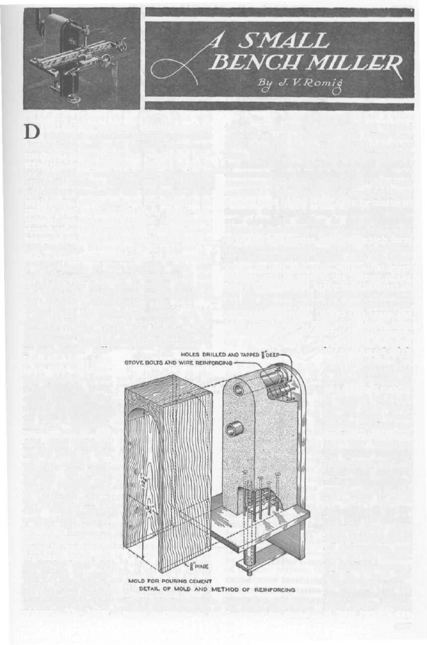
ing of the cement. The anchor bolts are
a micrometer cali-
per; if any bent
spots are discerni-
ble, straighten care-
fully, and if thick
spots occur in the
slides, scrape them
off until a level sur-
face is obtained.
The holes in the
front slide and base
should then be laid
off and drilled, in-
cluding the holes
for the spindle and
overarm, and the 1/4-
in. holes for the an-
chor bolts. These
anchor bolts are 1/4-
in. stove bolts of
varying lengths, as
shown in the smaller
drawing, and are
placed so that the
heads will be stag-
gered, to distribute
the hold and strains
more evenly in the
cement. The holes
i n t e r w o u n d w i t h
soft-iron wire, as
shown, and the form
is placed in position,
and clamped rigidly.
A mixture of 1 part
cement to 3 parts
clean, sharp sand
has proved ideal for
this purpose; dur-
ing the pouring,
the spaces between
the screws, and all
edges and corners,
must be thoroughly
poked with a knife,
o r o t h e r s h a r p -
pointed tool, to in-
sure that the cement
reaches every part.
After pouring, level
off the surface, and
then lay the assem-
bly aside to season;
this is a very im-
portant part of the
construction, the ce-
ment being wetted
at least twice a day
3557
The Main-Body Casting is Poured in a Mold Made
of Soft Pine, the Top of the Front Slide being
Shaped to Conform to the Contour of the Casting
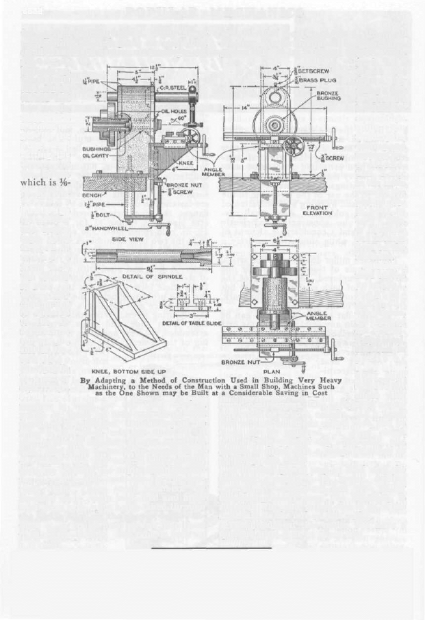
pattern is built for the knee casting,
which is made of soft gray iron, and
machined as indicated. On the top of the
knee is the main carriage slide; it is
machined very carefully on the edges and
faces, and must be perfectly square in all
directions. On the vertical sides of this
slide are screwed the angle members, two
for the table slide and two for the car-
riage slide. These angle members are
made of 3/16-in. angle iron, filed and fitted
with great care, a cut being taken through
the inside fillet, on the shaper, before fit-
ting; 1/4,-in. round-head screws hold them
to the carriage slide. The table is built up
round-head screws. The equipment neces-
sary, such as arbors, centers, and a small
vise with a homemade swivel base, can be
made up as required. A good chuck
should form part of the equipment, and
should be fitted with a flange threaded to
fit the spindle nose.
While foot power may be used with the
machine, a small 1/4-hp. motor, driving
through a countershaft and cone pulley
mounted directly over the machine, is
advised. The cone pulley should be of the
same size as the one on the miller.
The builder of this miller will have a
splendid little tool, at small cost.
p a r t s m a y
be made up.
The spindle
s h o u l d b e
turned and
b o r e d ,
using a No.
2 Morse ta-
per
in the
n o s e , a n d
cutting the
thread for
the chuck,
which is 1/16-
in.
pitch;
b r o n z e
b u s h i n g s
are used for
t h e b e a r -
ings, being
t u r n e d t o
m a k e a
press fit in
the spindle
p i p e . A
t h r e e - s t e p
cone pulley
i s t u r n e d
to the di-
m e n s i o n s
s h o w n ,
and
is
fas-
tened to
the spindle
by a safety
setscrew. A
s i m p l e
j o b c a n
b e s t b e
d o n e b y
using a few
r i v e t s t o
hold the as-
sembly,
while per-
forming the
drilling and
tapping op-
e r a t i o n s .
The T-slot
in the table
permits the
use
of
3/8-
in. bolts, to
hold a vise,
or the vari-
ous
fixtures
used on the
machine.
All screws
used on the
v e r t i c a l ,
l o n g i t u -
d i n a l , and
crossfeeds,
are turned
out of cold-
rolled steel,
and run
in
b r a s s o r
b r o n z e
n u t s , f a s -
tened to the
slides with
of cold-rolled steel, as shown in the detail
drawing, the various pieces being held to-
gether with 1/4 in. flat-head screws. This
for a period of about a week. While the ce-
ment is thus seasoning, the screws, slides,
spindle, knee, and various other component
3558
P O P U L A R M E C H A N I C S
Wyszukiwarka
Podobne podstrony:
Plans for Bench Grinder
Garret Water Carburator Plans For Water Powered Vehicles
Plans For Wind Generator Pt250 Blade Plan10A
My plans for the future
G20 in Mexico – New Plans for EU
Garret Water Carburator Plans For Water Powered Vehicles
Wood Working Plans for 6 inch Turret Lathe
Plans for radial drill press
England s Place in Hitler s Plans for World Dominion
Plans For Steam Marine Engine
Woodwork Plans For Hydraulic Press
Robert Krausz W d Gann Treasure Discovered Simple Trading Plans For Stocks & Commodities(pdf)
Plans For Drill Vise
plans for occilating steam engine 1185
37 509 524 Microstructure and Wear Resistance of HSS for Rolling Mill Rolls
Mill's Utilitarianism Sacrifice the Innocent For the Commo
A Bench for all Seasons lawka
więcej podobnych podstron