Making a Light Ball-Bearing
Column Grinder
By RAY F. KUNS
need of a grinder for light
work, such as sharpening drill bits,
bearing scrapers, punches and chisels,
and r o u g h i n g down light fittings for en-
gine stands, etc., the scrap pile was looked
over for parts that might lend themselves
to the building of such a machine. A
column was located and this was brought
up to proper height by fittinga brake drum
under it. It was desired to have the
motor mounted with the head so that the
machine might be set as a unit and moved
on occasion without a great deal of
trouble in re-alining parts.
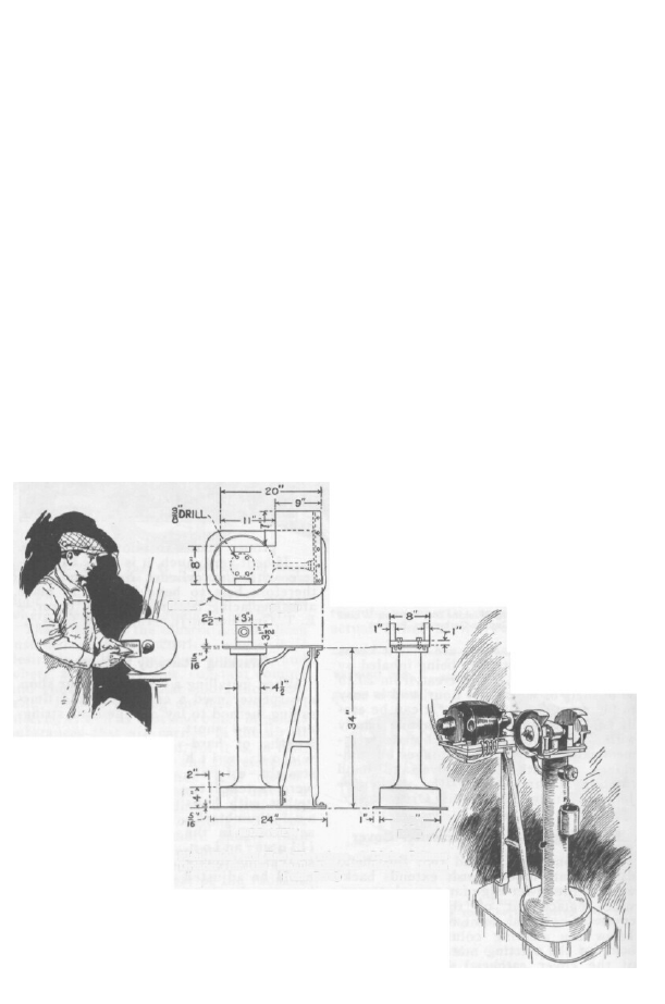
A piece of 5/16-in. boiler plate was ob-
tained and from it a base for the brake
drum and column was cut. Another piece
of the plate was shaped for the top plate
on which the grinder head and the motor
might be mounted. As a support be-
tween base and top, several lengths of
gas pipe were formed, and riveted and
bolted in place as indicated in the draw-
ing. A crossbar was welded into this
SIDE VIEW
brace to eliminate
any tendency to vi-
brate. The drawings
indicate the approxi-
mate dimensions of
the various p a r t s .
Before laying o u t
the plate with the
slots for the motor
support and adjust-
ment, however, it will be necessary to
have the motor at hand.
The motor used in this case is a single-
phase, 1/2-hp. machine. The pulley is 3¼
in., and drives the head pulley, which is 2
158
in. in diameter, at about 3,000 r.p.m., since
the motor speed is 1,800 r.p.m. A 2-in.
light single leather belt with a glued splice
is used to drive the grinder head. This
gives a drive free from any disturbing
vibration.
The construction of the head is rather
simple. The first consideration is the
bearings. Those used in this case were
salvaged from a worn-out motor genera-
tor. After the bearings are at hand some
dimensions may have to be varied to ac-
commodate them. Dimensions of shaft
diameters are given here in order to indi-
cate the approximate size desirable.
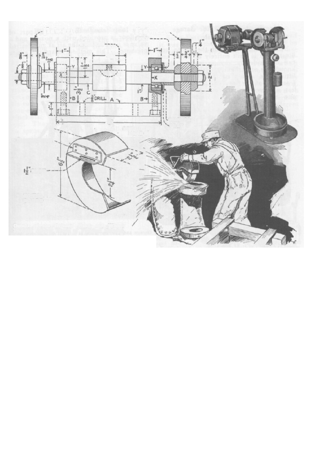
The blocks B, which are 1 in. thick and
3 in. wide, are chucked in the lathe and
bored out to accommodate the bearings
selected. Sufficient stock should be pro-
vided at the bottom of the blocks so they
can be bolted to the plate A as indicated.
After the supporting yoke, formed by the
parts A and B, has been bolted together
and the bearings installed, the exact di-
mensions of the shaft may be determined.
Where the shaft passes through the blocks
B, a little clearance is allowed to prevent
its rubbing. The distance between the
shoulders of the shaft, XX, must be slight-
ly greater than the distance between the
two points marked Y, otherwise the as-
sembling of the emery wheels on the shaft
would throw a
pressure on the
blocks B f r o m
t h e b e a r i n g
races.
It will be not-
ed that when the
13"
END
wheels are as-
sembled on the
shaft they are
locked between
flanges. These
H
AVING
Plan. Side and End Elevations of Light Column
Grinder for the Small Shop or Garage, Made
from Scrap
PLAN
BASE
P O P U L A R M E C H A N I C S
159
force the 1.125-in. collars against recessed
washers, which are in turn forced against
the inner bearing races. This arrange-
ment locks the parts together in such
fashion that there is no end play other
than that previously mentioned at X and
Y. Since the races of the ball bearings
are free at Y and rest against the felt
washers on their outer faces, they are left
free to properly aline themselves and, in
case of need, will float in their housings
a slight amount in either direction. When
mounting well-fitted ball bearings, it is
essential that this provision be made.
Otherwise the heat generated in the shaft
when the machine is in operation may be
great enough to expand the shaft and
throw an undue strain on the bearings.
The washers are recessed on one side to
provide for felt rings, which are depended
on to prevent dirt and grit from entering
the bearings.
The shaft C may be made with the pul-
ley integral from a 2¼-in. round machine-
steel bar, or an old axle or propeller shaft
may be used and the pulley made and se-
cured on it as indicated. When assem-
bling the shaft, it is necessary to remove
one of the end blocks B. The threads are
cut to run tight, as the load comes on
the wheel. This means that right-hand
threads are cut on the right end and left-
hand threads on the left end of the shaft.
When mounting the head on the col-
umn, reasonable care must be used to
see that it is not cramped or warped in
such a fashion that the alignment of the
bearings will be affected. The head
is mounted 2½ in. from the front edge of
the top plate of the column. This space
may be used to accommodate the rests.
These are made from machine steel. A
bar of .625-in. steel has one end forged flat
and bent over at right angles: the other
end is threaded. This forms the rest for
the work being ground and it is supported
in a machine-steel plate ¼ by 1½ by 4 in.,
having a hole in each end. Knurled
thumbscrews are used to lock the sup-
porting plates in position.
The guards for the grinder wheels are
made from 16-gauge sheet iron, fitted so
as to be centered when the wheels are
new. They are supported on the blocks B
by means of an angle plate riveted to the
guard and fastened to the block with a
capscrew. Adjustment of the guard is ef-
fected by means of a slot in the angle plate.
No special provision is made for greas-
ing or oiling the bearings.
Details of the Grinder Head and Wheel
Guards; Above, Photo of Finished Grinder
WHEEL
GUARD
SLOT
1" ANGLE IRON
DETAIL OF
HEAD
8"
FELT
WASHER
FELT
¾" x 6" WHEEL
½" x 6" WHEEL
2" PULLEY
2½"
Wyszukiwarka
Podobne podstrony:
Plans for horizontal Bench Mill
Garret Water Carburator Plans For Water Powered Vehicles
Plans For Wind Generator Pt250 Blade Plan10A
My plans for the future
G20 in Mexico – New Plans for EU
Garret Water Carburator Plans For Water Powered Vehicles
Woodworking Plans Garden Bench(1)
Wood Working Plans for 6 inch Turret Lathe
Plans for radial drill press
England s Place in Hitler s Plans for World Dominion
Plans For Steam Marine Engine
Woodwork Plans For Hydraulic Press
Robert Krausz W d Gann Treasure Discovered Simple Trading Plans For Stocks & Commodities(pdf)
Plans For Drill Vise
plans for occilating steam engine 1185
A Bench for all Seasons lawka
więcej podobnych podstron