By E. S. Harris
OR fitting bushings into con-
necting rods, forcing gears on
shafts, removing axles from small
wheels and similar work in the
garage, service station or shop, a
hydraulic press like the one illus-
trated will do the job quickly and
efficiently. It consists of a hydrau-
lic auto jack, some pipe and pipe
fittings and a frame made from
odds and ends of scrap iron usual-
F
ly available at garages and machine shops.
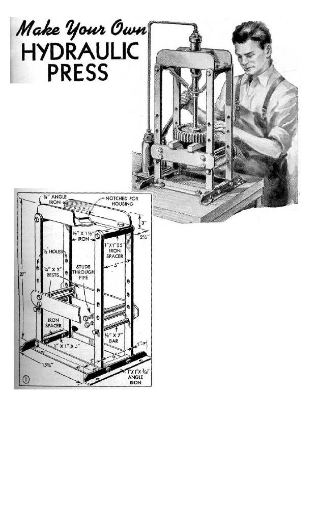
Four pieces of angle iron forming the
base are bolted to the workbench, and the
uprights are attached with ½-in. bolts.
Four spacers, shown in Fig. 1, are drilled
and tapped for ½-in. bolts which hold them
to the uprights. The top of the press is
made from two lengths of angle iron which
are bolted to the spacers. A notch is cut in
each piece of angle iron through which the
jack will be inserted later, and two steel
retaining blocks, similarly notched as
shown in the circular detail of Fig. 2, are
drilled and tapped for two ½-in. bolts on
each side and on the underside to receive
a similar bolt extending through the slot
where the pieces of angle iron butt togeth-
er. The adjustable rests are supported at
any one of four positions by bars placed
through ½-in. holes spaced at 3-in. inter-
vals in the uprights, and are held together
tightly by four studs running through sec-
tions of iron pipe.
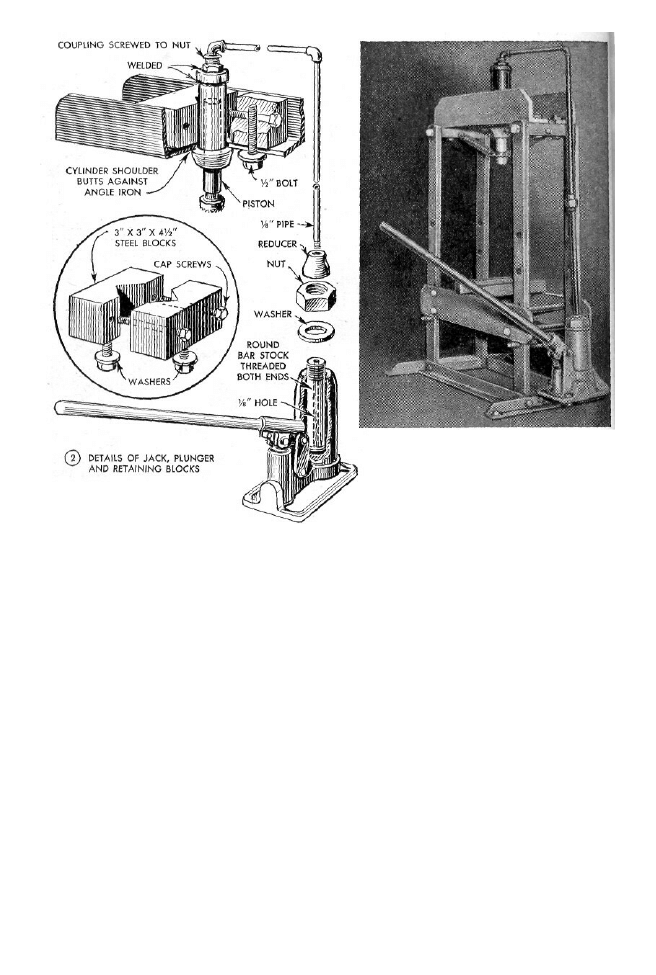
The cylinder and piston
of the hydraulic jack are
removed as a unit, and a
piece of round bar stock of the same diam-
eter and length as the cylinder is substi-
tuted. A hole is drilled through it length-
wise for the passage of fluid, and the ends
are threaded, one end to screw into the
base of the jack housing, the other to take
a nut and pipe reducer into which the feed
pipe is to be fitted. After the bar is screwed
into the housing, a washer is placed over
it and the nut turned down tightly to pre-
vent loss of fluid. It may be necessary to
put a gasket under the washer as a seal.
Instead of using a reducer, the feed pipe
can be threaded and fitted into a counter-
bored, tapped hole in the bar.
Next, make a housing for the cylinder
and piston. This is made from a length of
1¾-in. iron pipe about half as long as the
cylinder, welded to a metal base which is
threaded like the jack housing to receive
the cylinder, and is drilled for the passage
of fluid. A nut is welded to the base and a
feed-pipe coupling screwed into it. The
cylinder and piston in the substitute hous-
ing are mounted on the frame as shown in
the upper detail of Fig. 2, with the end of
the housing resting on the angle iron and
the cylinder shoulder butting up against
the underside of the angle iron. The hous-
ing is clamped securely between the
retaining blocks. In this position, the
piston will press down on the work
when fluid is pumped into the cylinder.
The feed pipe is attached by couplings
and elbows, and the jack is supported
by a brace at the side of the frame. Coil
springs, attached to the frame spacers by
eye bolts, pull up the piston and force the
fluid back when the valve is released.
Wyszukiwarka
Podobne podstrony:
Diy Workshop Woodwork Plans Drawings For Homemade Wood Lathe
Plans for radial drill press
(Ebooks) DIY Woodwork Plans Drill Press Table
Garret Water Carburator Plans For Water Powered Vehicles
Plans For Wind Generator Pt250 Blade Plan10A
My plans for the future
(madera) Woodworking plans Workbench Popular Mechanics Hard Maple
G20 in Mexico – New Plans for EU
Garret Water Carburator Plans For Water Powered Vehicles
eBook DIY Woodworking Plans Guide To Wood Finishing
2 Woodworking plans settletable
(EBooks) DIY Woodwork Plans 10 Workbench Accessories
Woodworking Tools for Carving
Woodworking Plans Garden Bench(1)
Plans for horizontal Bench Mill
Plans for Bench Grinder
2 Woodworking Plans Standing Router Table
więcej podobnych podstron