
SAFETY.CAT.COM™
C18
MARINE ENGINE
Maintenance Intervals
Excerpted from Operation & Maintenance Manual (SEBU7689-10)
®
© 2009 Caterpillar
All Rights Reserved
®

SEBU7689-10
81
Maintenance Section
Maintenance Interval Schedule
i03542891
Maintenance Interval Schedule
SMCS Code: 1000; 7500
Ensure that all safety information, warnings and
instructions are read and understood before any
operation or any maintenance procedures are
performed.
The user is responsible for the performance of
maintenance, including all adjustments, the use of
proper lubricants, fluids, filters, and the replacement
of components due to normal wear and aging. Failure
to adhere to proper maintenance intervals and
procedures may result in diminished performance of
the product and/or accelerated wear of components.
Use distance, fuel consumption, service hours, or
calendar time, WHICH EVER OCCURS FIRST,
in order to determine the maintenance intervals.
Products that operate in severe operating conditions
may require more frequent maintenance.
Note: Before each consecutive interval is performed,
all maintenance from the previous interval must be
performed.
Some maintenance intervals will depend on the
operating environment of the vessel and on the
operating time. Operating in water that contains silt,
sediment, the algae and salt will adversely affect the
maintenance intervals for some items. In addition,
intermittent use of the vessel will adversely affect the
maintenance intervals for some items.
When Required
Battery - Recycle .................................................. 85
Battery - Replace .................................................. 85
Battery or Battery Cable - Disconnect .................. 86
Engine - Clean .................................................... 100
Engine Oil Level Gauge - Calibrate .................... 104
Engine Storage Procedure - Check ..................... 110
Fuel System - Prime ............................................ 112
Heat Exchanger - Inspect ................................... 121
Maintenance Recommendations ........................ 123
Sea Water Strainer - Clean/Inspect .................... 129
Zinc Rods - Inspect/Replace ............................... 132
Daily
Closed Crankcase Ventilation (CCV) Filter Service
Indicator - Inspect ............................................... 87
Cooling System Coolant Level - Check ................ 95
Engine Air Cleaner Service Indicator - Inspect ... 102
Engine Oil Level - Check .................................... 103
Fuel System Primary Filter/Water Separator -
Drain .................................................................. 114
Walk-Around Inspection ...................................... 131
Initial 20 to 40 Service Hours
Belts - Inspect/Adjust/Replace .............................. 86
Every 50 Service Hours or Weekly
Aftercooler Condensate Drain Valve -
Inspect/Clean ...................................................... 83
Sea Water Strainer - Clean/Inspect .................... 129
Zinc Rods - Inspect/Replace ............................... 132
Initial 500 Hours (for New Systems, Refilled
Systems, and Converted Systems)
Cooling System Coolant Sample (Level 2) -
Obtain ................................................................. 98
Every 500 Service Hours
Cooling System Coolant Sample (Level 1) -
Obtain ................................................................. 96
Every Year
Cooling System Coolant Sample (Level 2) -
Obtain ................................................................. 98
Every 6000 Service Hours or 3 Years
Cooling System Coolant Extender (ELC) - Add .... 95
Every 12 000 Service Hours or 6 Years
Cooling System Coolant (ELC) - Change ............. 92
First 14 400 L (3750 US gal) of Fuel or 250
Service Hours
Engine Valve Lash - Inspect/Adjust ..................... 110
Fuel Injector - Inspect/Adjust ............................... 111
Every 14 400 L (3750 US gal) of Fuel or 250
Service Hours or 1 Year
Auxiliary Water Pump (Rubber Impeller) -
Inspect ................................................................ 85
Battery Electrolyte Level - Check .......................... 86
Belts - Inspect/Adjust/Replace .............................. 86
Cooling System Supplemental Coolant Additive
(SCA) - Test/Add ................................................. 98
Engine - Clean .................................................... 100
Engine Air Cleaner Element - Clean/Replace ..... 100
Engine Crankcase Breather - Clean ................... 102
Engine Oil Sample - Obtain ................................ 105
Engine Oil and Filter - Change ........................... 105
Fuel System Primary Filter (Water Separator)
Element - Replace ............................................. 113
Fuel System Secondary Filter - Replace ............. 115
Fuel Tank Water and Sediment - Drain ............... 120
Hoses and Clamps - Inspect/Replace ................ 122

82
SEBU7689-10
Maintenance Section
Maintenance Interval Schedule
Every 28 500 L (7500 US gal) of Fuel or 500
Service Hours or 1 Year (Deep Sump)
Engine Oil and Filter - Change ........................... 105
Every 57 000 L (15 000 US gal) of Fuel or
1000 Service Hours
Aftercooler Core - Clean/Test ............................... 83
Closed Crankcase Ventilation (CCV) Fumes Disposal
Filter - Replace .................................................... 87
Heat Exchanger - Inspect ................................... 121
Turbocharger - Inspect ........................................ 130
Every 170 400 L (45 000 US gal) of Fuel or
3000 Service Hours
Auxiliary Water Pump (Bronze Impeller) -
Inspect ................................................................ 84
Cooling System Coolant (DEAC) - Change .......... 89
Cooling System Water Temperature Regulator -
Replace ............................................................... 99
Crankshaft Vibration Damper - Inspect ................. 99
Engine Mounts - Inspect ..................................... 103
Engine Speed/Timing Sensor - Clean/Inspect .... 109
Engine Valve Lash - Inspect/Adjust ..................... 110
Engine Valve Rotators - Inspect .......................... 111
Fuel Injector - Inspect/Adjust ............................... 111
Starting Motor - Inspect ...................................... 129
Every 284 000 L (75 000 US gal) of Fuel or
5000 Service Hours
Alternator - Inspect ............................................... 84
Maintenance Recommendations ........................ 123
Oil Cooler Core - Check/Clean/Test .................... 125
Overhaul (Top End) ............................................. 128
Water Pump - Inspect ......................................... 132
Every 570 000 L (150 000 US gal) of Fuel or
10 000 Service Hours
Maintenance Recommendations ........................ 123
Overhaul (Major) ................................................. 126
SEBU7689-10
83
Maintenance Section
Aftercooler Condensate Drain Valve - Inspect/Clean
i03626622
Aftercooler Condensate Drain
Valve - Inspect/Clean
SMCS Code: 1063-042-DN, VL
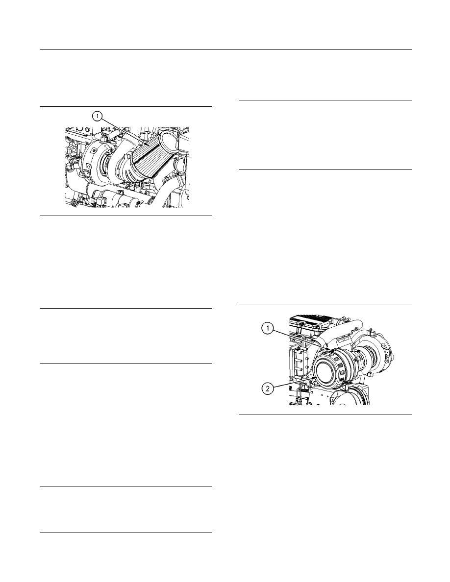
NOTICE
Failure to keep the condensate drain valve functional
can cause severe damage to the engine.
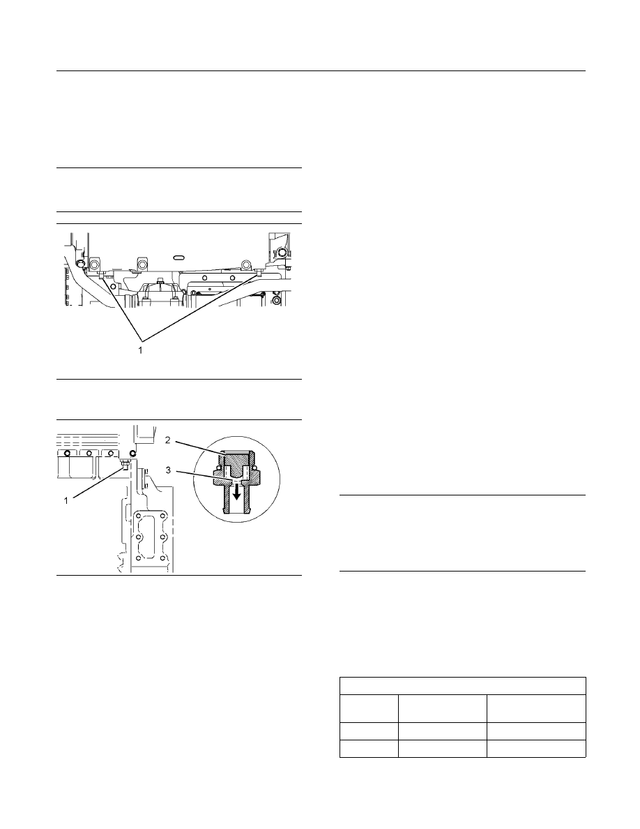
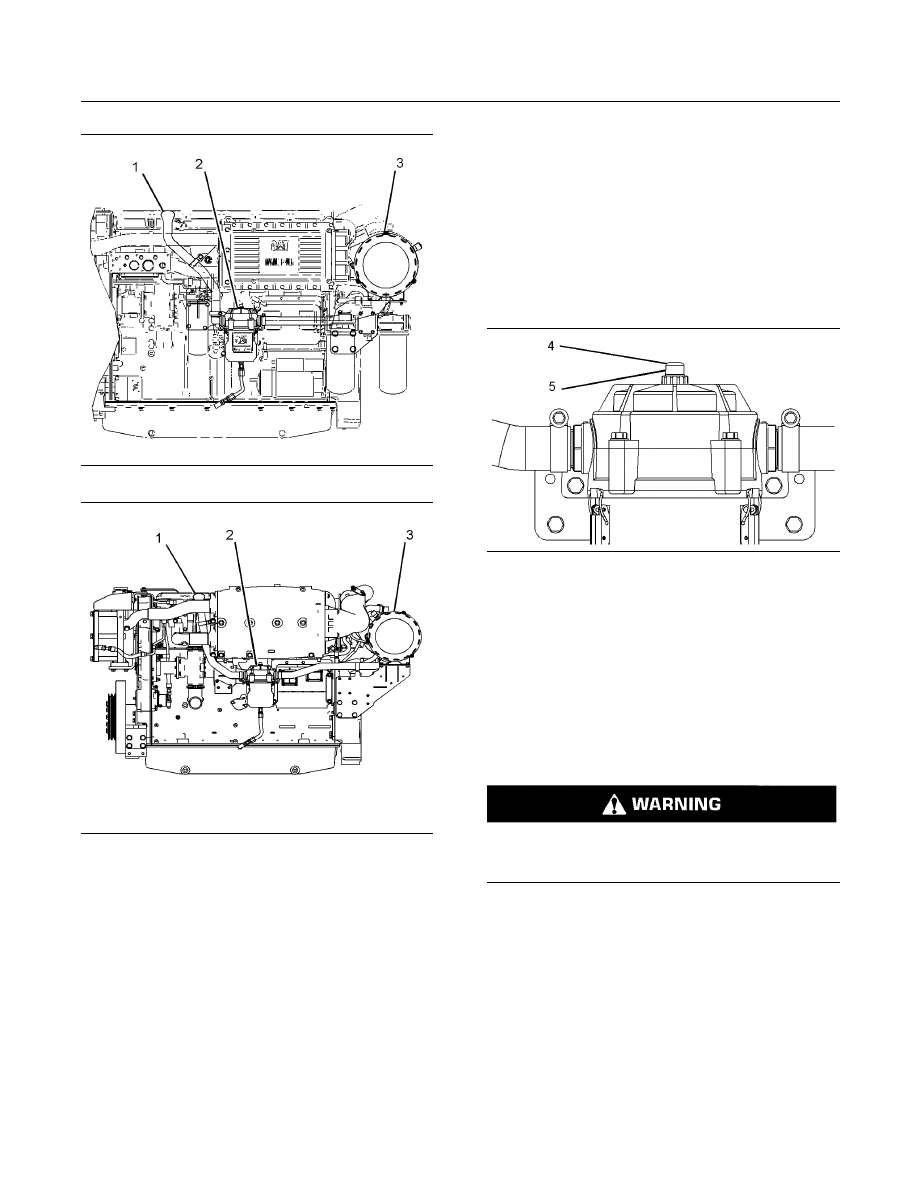
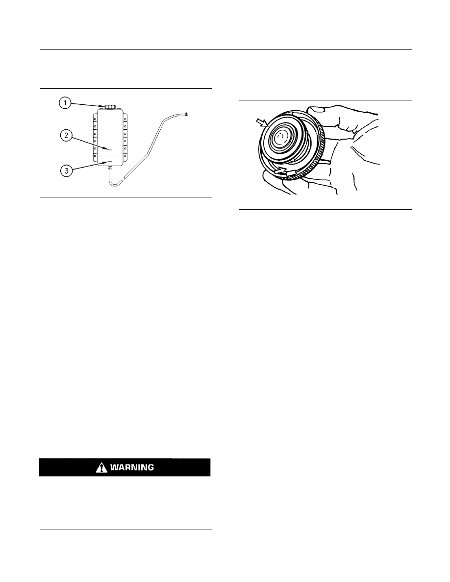
g01638393
Illustration 37
Typical
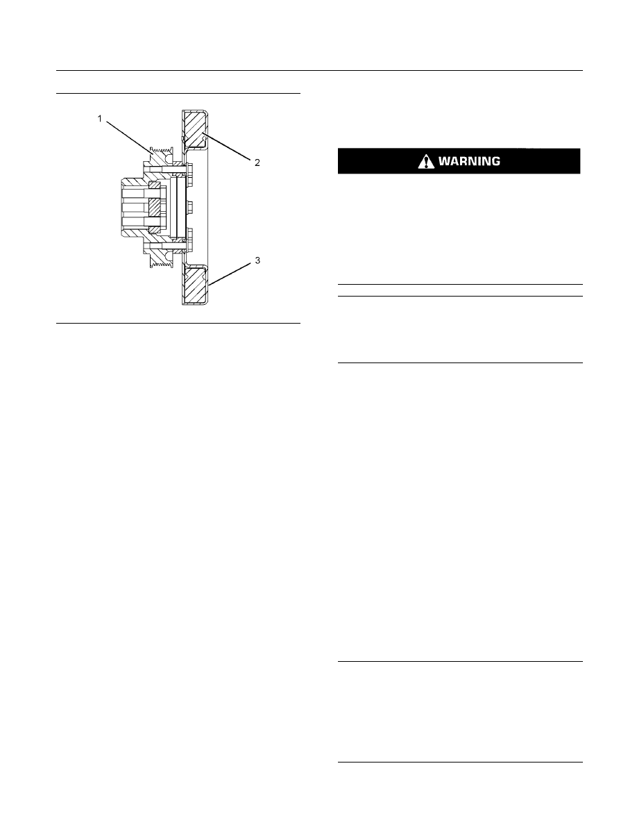
g01348104
Illustration 38
(1) Valve
(2) Plunger
(3) Valve seat
The engine boost pressure forces the plunger to
move down to the valve seat. The plunger must
close against the seat at a pressure of 27.5 kPa
(4 psi). When the engine is stopped, the absence
of boost pressure allows the plunger to rise to the
open position, which allows condensation from the
aftercooler to drain out.
The plunger must be able to move freely in order to
close the system when the engine is running. The
plunger must be able to move freely in order to allow
condensation to drain from the aftercooler when
the engine is stopped. Residue from normal engine
operation could cause the plunger to stick.
1. Remove the valve from the adapter. Check the
valve in order to determine if the plunger moves
freely. If the plunger does not move easily, clean
the valve with solvent.
2. Reassemble the aftercooler condensate drain
valve. See Specifications Manual, SENR3130,
“Torque Specifications” for more information on
the proper torques.
i03635591
Aftercooler Core - Clean/Test
SMCS Code: 1064-070; 1064-081
Note: An aftercooler that circulates fresh water
or treated water may require cleaning less often
than an aftercooler which circulates salt water.
The maintenance interval for an aftercooler which
circulates fresh water or treated water should be
evaluated when the aftercooler is cleaned and tested
after the first 1000 hours of engine operation. The
interval will vary depending on operating conditions.
Clean the Aftercooler Core
Remove the core. Refer to the Disassembly and
Assembly Manual, “Aftercooler - Remove” for the
procedure.
1. Turn the aftercooler core on one side in order
to remove debris. Remove the debris that is
accessible.
NOTICE
Do not use a high concentration of caustic cleaner to
clean the core. A high concentration of caustic cleaner
can attack the internal metals of the core and cause
leakage. Only use the recommended concentration of
cleaner.
2. Back flush the core with cleaner.
Caterpillar recommends the use of Hydrosolv
liquid cleaner. Table 13 lists Hydrosolv liquid
cleaners that are available from your Caterpillar
dealer.
Table 13
Hydrosolv Liquid Cleaners
(1)
Part
Number
Description
Size
1U-5490
Hydrosolv 4165
19 L (5 US gallon)
174-6854
Hydrosolv 100
19 L (5 US gallon)
(1)
Use a two to five percent concentration of the cleaner
at temperatures up to 93°C (200°F). Refer to Application
Guide, NEHS0526 or consult your Caterpillar dealer for more
information.

84
SEBU7689-10
Maintenance Section
Alternator - Inspect
3. Steam clean the core in order to remove any
residue. Flush the fins of the aftercooler core.
Remove any other trapped debris from the inside
and from the outside of the core.
Note: Do not use high pressure when the fins are
cleaned. High pressure can damage the fins.
4. Wash the core with hot, soapy water.
5. Flush the core thoroughly in order to remove
residue and remaining debris. Flush the core with
clean, fresh water until the water that is exiting the
core is clear and free of debris.
Personal injury can result from air pressure.
Personal injury can result without following prop-
er procedure. When using pressure air, wear a pro-
tective face shield and protective clothing.
The maximum air pressure for cleaning purposes
must be reduced to 205 kPa (30 psi) when the air
nozzle is deadheaded.
6. Dry the core with compressed air. Direct the air in
the reverse direction of the normal flow.
Test the Aftercooler Core
1. Inspect the core for trapped debris and
cleanliness. If necessary, remove the debris and
repeat the cleaning procedure.
2. Inspect the core for damage and perform a
pressure test in order to detect leaks. Many shops
that service radiators are equipped to perform
pressure tests.
3. Plug both ends of the aftercooler core and
pressurize the core to 205 kPa (30 psi). Submerge
the core in water. Look for bubbles which are
being emitted from the core. The bubbles are
evidence of leaks.
4. If any leaks are found, do not attempt to repair the
core.
Install a core that is clean and a core that passes the
pressure test in step 3. Refer to the Disassembly
and Assembly Manual, “Aftercooler - Install” for the
procedure.
For more information on cleaning the core, consult
your Caterpillar dealer.
i02676048
Alternator - Inspect
SMCS Code: 1405-040
Caterpillar recommends a scheduled inspection
of the alternator. Inspect the alternator for loose
connections and proper battery charging. Inspect the
ammeter (if equipped) during engine operation in
order to ensure proper battery performance and/or
proper performance of the electrical system. Make
repairs, as required.
Check the alternator and the battery charger for
proper operation. If the batteries are properly
charged, the ammeter reading should be very near
zero. All batteries should be kept charged. The
batteries should be kept warm because temperature
affects the cranking power. If the battery is too cold,
the battery will not crank the engine. The battery will
not crank the engine, even if the engine is warm.
When the engine is not run for long periods of time
or if the engine is run for short periods, the batteries
may not fully charge. A battery with a low charge will
freeze more easily than a battery with a full charge.
i01042055
Auxiliary Water Pump (Bronze
Impeller) - Inspect
SMCS Code: 1371-040
Impellers and seals require periodic inspection.
Impellers have a service life that is limited. The
service life depends on the engine operating
conditions.
Inspect the components more frequently when the
pump is exposed to debris, sand, or other abrasive
materials. Inspect the components if the pump is
operating at a differential pressure of more than
103 kPa (15 psi).
Check the following components for wear or damage:
•
Bearings
•
Impeller
•
Seals
•
Wear plate
If wear or damage is found, replace the components
which are worn or damaged. Use the proper repair
kit for the pump. Refer to the Disassembly and
Assembly for more information on servicing the
auxiliary water pump.
SEBU7689-10
85
Maintenance Section
Auxiliary Water Pump (Rubber Impeller) - Inspect
i01041983
Auxiliary Water Pump (Rubber
Impeller) - Inspect
SMCS Code: 1371-040
Impellers and seals require periodic inspection.
Impellers have a service life that is limited. The
service life depends on the engine operating
conditions.
Inspect the components more frequently when the
pump is exposed to debris, sand, or other abrasive
materials. Inspect the components if the pump is
operating at a differential pressure of more than
103 kPa (15 psi).
Check the following components for wear or damage:
•
Bearings
•
Impeller
•
Seals
•
Wear plate
If wear or damage is found, replace the components
which are worn or damaged. Use the proper repair
kit for the pump. Refer to the Disassembly and
Assembly for more information on servicing the
auxiliary water pump.
i00993589
Battery - Recycle
SMCS Code: 1401-561
Always recycle a battery. Never discard a battery.
Always return used batteries to one of the following
locations:
•
A battery supplier
•
An authorized battery collection facility
•
Recycling facility
i02153996
Battery - Replace
SMCS Code: 1401-510
Batteries give off combustible gases which can
explode. A spark can cause the combustible gas-
es to ignite. This can result in severe personal in-
jury or death.
Ensure proper ventilation for batteries that are in
an enclosure. Follow the proper procedures in or-
der to help prevent electrical arcs and/or sparks
near batteries. Do not smoke when batteries are
serviced.
The battery cables or the batteries should not be
removed with the battery cover in place. The bat-
tery cover should be removed before any servic-
ing is attempted.
Removing the battery cables or the batteries with
the cover in place may cause a battery explosion
resulting in personal injury.
1. Turn the key start switch to the OFF position.
Remove the key and all electrical loads.
2. Turn OFF the battery charger. Disconnect the
charger.
3. The NEGATIVE “-” cable connects the NEGATIVE
“-” battery terminal to the ground plane. Disconnect
the cable from the NEGATIVE “-” battery terminal.
4. The POSITIVE “+” cable connects the POSITIVE
“+” battery terminal to the starting motor.
Disconnect the cable from the POSITIVE “+”
battery terminal.
Note: Always recycle a battery. Never discard a
battery. Return used batteries to an appropriate
recycling facility.
5. Remove the used battery.
6. Install the new battery.
Note: Before the cables are connected, ensure that
the key start switch is OFF.
7. Connect the cable from the starting motor to the
POSITIVE “+” battery terminal.
86
SEBU7689-10
Maintenance Section
Battery Electrolyte Level - Check
8. Connect the cable from the ground plane to the
NEGATIVE “-” battery terminal.
i02601752
Battery Electrolyte Level -
Check
SMCS Code: 1401-535
When the engine is not run for long periods of time or
when the engine is run for short periods, the batteries
may not fully recharge. Ensure a full charge in order
to help prevent the battery from freezing.
All lead-acid batteries contain sulfuric acid which
can burn the skin and clothing. Always wear a face
shield and protective clothing when working on or
near batteries.
1. Remove the filler caps. Maintain the electrolyte
level to the “FULL” mark on the battery.
If the addition of water is necessary, use distilled
water. If distilled water is not available use clean
water that is low in minerals. Do not use artificially
softened water.
2. Check the condition of the electrolyte with the
245-5829 Coolant Battery Tester Refractometer.
3. Keep the batteries clean.
Clean the battery case with one of the following
cleaning solutions:
•
A mixture of 0.1 kg (0.2 lb) of baking soda and
1 L (1 qt) of clean water
•
A mixture of 0.1 L (0.11 qt) of ammonia and 1 L
(1 qt) of clean water
Thoroughly rinse the battery case with clean water.
Use a fine grade of sandpaper to clean the
terminals and the cable clamps. Clean the items
until the surfaces are bright or shiny. DO NOT
remove material excessively. Excessive removal
of material can cause the clamps to not fit properly.
Coat the clamps and the terminals with
5N-5561
Silicone Lubricant, petroleum jelly or MPGM.
i01492654
Battery or Battery Cable -
Disconnect
SMCS Code: 1402-029
The battery cables or the batteries should not be
removed with the battery cover in place. The bat-
tery cover should be removed before any servic-
ing is attempted.
Removing the battery cables or the batteries with
the cover in place may cause a battery explosion
resulting in personal injury.
1. Turn the start switch to the OFF position. Turn the
ignition switch (if equipped) to the OFF position
and remove the key and all electrical loads.
2. Disconnect the negative battery terminal at the
battery that goes to the start switch. Ensure that
the cable cannot contact the terminal. When four
12 volt batteries are involved, the negative side of
two batteries must be disconnected.
3. Tape the leads in order to help prevent accidental
starting.
4. Proceed with necessary system repairs. Reverse
the steps in order to reconnect all of the cables.
i02856850
Belts - Inspect/Adjust/Replace
SMCS Code: 1357-025; 1357-040; 1357-510
Inspection
Inspect the alternator belt and any accessory belts
for wear and for cracking. Replace the belts if the
belts are not in good condition.
To check the belt tension, apply 110 N (25 lb) of force
midway between the pulleys. A correctly adjusted
belt will deflect 13 to 19 mm (0.50 to 0.75 inch).
Slippage of loose belts can reduce the efficiency
of the driven components. Vibration of loose belts
can cause unnecessary wear on the following
components:
•
Belts
•
Pulleys
SEBU7689-10
87
Maintenance Section
Closed Crankcase Ventilation (CCV) Filter Service Indicator - Inspect
•
Bearings
If the belts are too tight, unnecessary stress is placed
on the components. This reduces the service life of
the components.
Replacement
For applications that require multiple drive belts,
replace the drive belts in matched sets. Replacing
one drive belt of a matched set will cause the new
drive belt to carry more load because the older drive
belts are stretched. The additional load on the new
drive belt could cause the new drive belt to fail.
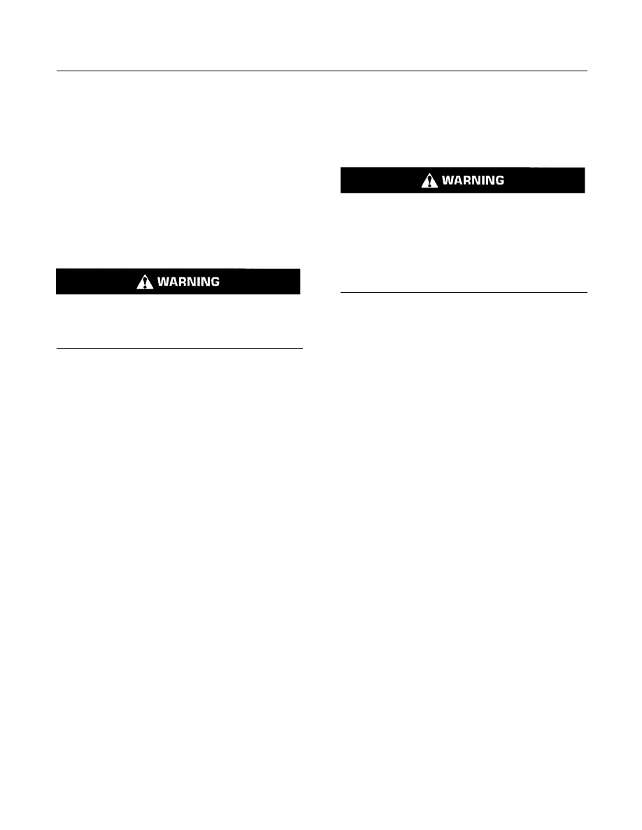
Alternator Belt Adjustment
g00960176
Illustration 39
(1) Adjusting nuts
(2) Mounting bolt
(3) Mounting bolt
(4) Mounting bolt
1. Remove the drive belt guard.
2. Loosen mounting bolts (2), (3), and (4). Loosen
adjusting nuts (1).
3. Turn adjusting nuts (1) in order to increase or
decrease the drive belt tension.
4. Tighten adjusting nuts (1). Tighten mounting bolts
(2), (3), and (4).
5. Reinstall the drive belt guard.
If new drive belts are installed, check the drive belt
tension again after 30 minutes of engine operation at
the rated rpm.
i01852860
Closed Crankcase Ventilation
(CCV) Filter Service Indicator
- Inspect
SMCS Code: 1317-040-FI
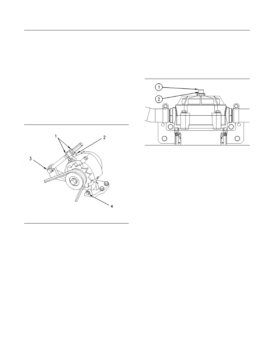
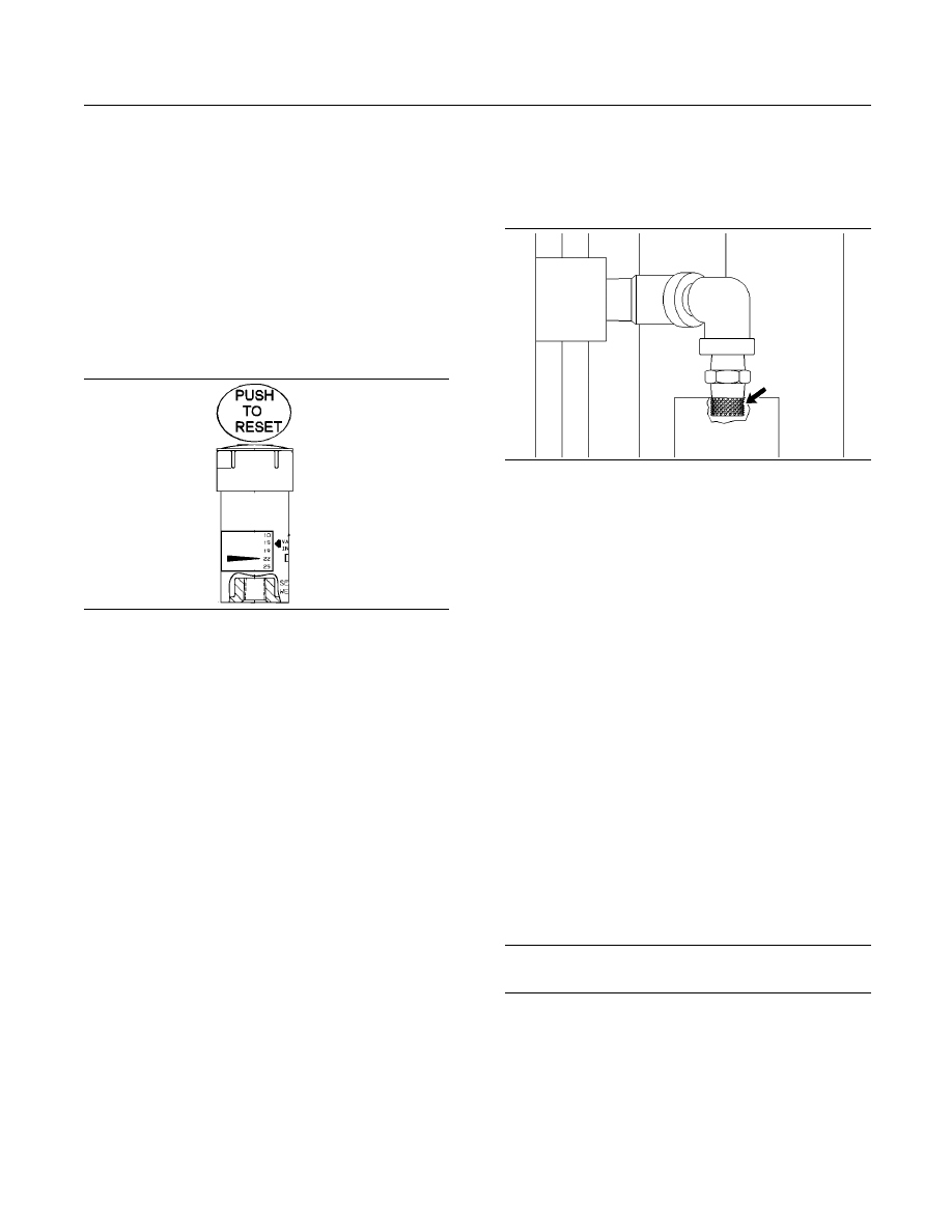
g00744250
Illustration 40
(1) Plastic cover
(2) Service indicator
The Closed Crankcase Ventilation system (CCV)
is equipped with a service indicator. If the fumes
disposal filter becomes plugged prior to the normal
service interval, increased restriction of the filter will
cause the crankcase pressure to become positive.
When the pressure continues to rise, the service
indicator will show through the plastic cover. The
service indicator indicates the need for the fumes
disposal filter to be changed. Refer to the Operation
and Maintenance Manual, “Closed Crankcase
Ventilation (CCV) Fumes Disposal Filter - Replace”
topic for more information.
Note: Check the service indicator when the engine is
running at low idle.
i03615046
Closed Crankcase Ventilation
(CCV) Fumes Disposal Filter -
Replace
SMCS Code: 1317-510-FI
The engine may look like one of the engines which
are pictured below.
88
SEBU7689-10
Maintenance Section
Closed Crankcase Ventilation (CCV) Fumes Disposal Filter - Replace
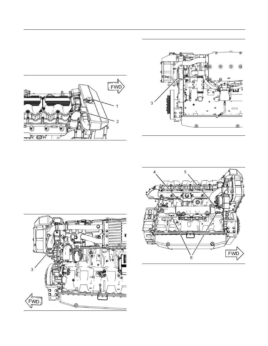
g01637464
Illustration 41
g01637466
Illustration 42
(1) Crankcase breather
(2) Filter base and filter for fumes disposal
(3) Air cleaner
The Closed Crankcase Ventilation system (CCV)
requires the replacement of the fumes disposal filter.
The service interval of the CCV will be affected by
the following items:
•
Engine load
•
Soot concentration
•
Condition of the engine
The CCV is equipped with a service indicator. If the
fumes disposal filter becomes plugged prior to the
normal service interval, increased restriction of the
filter will cause the vacuum to become positive. When
the pressure continues to rise, the service indicator
will show through the cap. The service indicator
indicates the need for the fumes disposal filter to be
changed. Reset the service indicator by using the
following procedure:
Resetting the Service Indicator
g01292899
Illustration 43
(4) Plastic cover
(5) Service indicator
1. Remove the plastic cover.
2. Push down on the service indicator.
3. Replace the cover.
Replacing the Fumes Disposal
Filter
Hot oil and hot components can cause personal
injury. Do not allow hot oil or hot components to
contact the skin.
Note: When possible, perform the maintenance while
the engine is off.
SEBU7689-10
89
Maintenance Section
Cooling System Coolant (DEAC) - Change
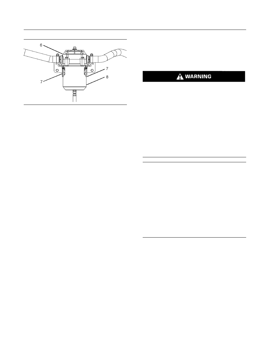
g01938796
Illustration 44
(6) Filter base assembly
(7) Latches
(8) Canister
1. Release the latches that hold the canister to the
filter base assembly .
Note: Removal of the canister may be difficult while
the engine is operating. The canister has negative air
pressure while the engine is operating. This creates
a vacuum.
2. Lower the canister in order to expose the element.
There may be oil in the bottom of the canister.
Avoid spilling the oil.
3. Remove the filter element by pulling down.
Dispose of the used element properly.
4. Remove the O-ring assembly on the top end cap
of the used element.
5. Replace the O-ring seal on the bottom of the filter
base assembly.
6. Install the new O-ring on the top end cap of the
element. Install the element into the correct place.
7. Replace the canister and align the canister with
the boss on the filter base assembly.
8. Clamp the latches in the closed position.
i03211768
Cooling System Coolant
(DEAC) - Change
SMCS Code: 1350-070; 1395-044
Personal injury can result from hot coolant, steam
and alkali.
At operating temperature, engine coolant is hot
and under pressure. The heat exchanger and all
lines to heaters or the engine contain hot coolant
or steam. Any contact can cause severe burns.
Remove the filler cap slowly to relieve pressure
only when the engine is stopped and the filler cap
for the heat exchanger is cool enough to touch
with your bare hand.
Cooling System Conditioner contains alkali. Avoid
contact with skin and eyes.
NOTICE
Care must be taken to ensure that fluids are contained
during performance of inspection, maintenance, test-
ing, adjusting and repair of the product. Be prepared to
collect the fluid with suitable containers before open-
ing any compartment or disassembling any compo-
nent containing fluids.
Refer to Special Publication, NENG2500, “Caterpillar
Dealer Service Tool Catalog” for tools and supplies
suitable to collect and contain fluids on Caterpillar
products.
Dispose of all fluids according to local regulations and
mandates.
Clean the cooling system and flush the cooling
system before the recommended maintenance
interval if the following conditions exist:
•
The engine overheats frequently.
•
Foaming of the coolant
•
The oil has entered the cooling system and the
coolant is contaminated.
•
The fuel has entered the cooling system and the
coolant is contaminated.

90
SEBU7689-10
Maintenance Section
Cooling System Coolant (DEAC) - Change
Note: Inspect the water pump and the water
temperature regulator after the cooling system has
been drained. This is a good opportunity to replace
the water pump, the water temperature regulator and
the hoses, if necessary.
Drain
g01355994
Illustration 45
1. Stop the engine and allow the engine to cool.
Loosen expansion tank filler cap (1) slowly in order
to relieve any pressure. Remove the expansion
tank filler cap.
2. Open the cooling system drain valve (if equipped).
3. In order to fully drain the coolant, remove the
following plugs:
a. Remove plug (2) in order to vent the water near
the water temperature regulator.
g01355995
Illustration 46
Commercial application
g01637916
Illustration 47
Pleasure craft
b. Remove drain plug (3) from the bottom heat
exchanger.
g01355996
Illustration 48
c. Remove drain plug (4) from the bottom of the
water cooled exhaust manifold.
d. Remove drain plugs (5) from the bottom of the
jacket water pump inlet.
e. Remove drain plug (6) from the bottom of the
oil cooler.
4. Allow coolant to drain.

SEBU7689-10
91
Maintenance Section
Cooling System Coolant (DEAC) - Change
NOTICE
Dispose of used engine coolant properly or recycle.
Various methods have been proposed to reclaim used
coolant for reuse in engine cooling systems. The full
distillation procedure is the only method acceptable by
Caterpillar to reclaim the used coolant.
For information regarding the disposal and the
recycling of used coolant, consult your Caterpillar
dealer or consult Caterpillar Service Technology
Group:
Outside Illinois: 1-800-542-TOOL
Inside Illinois: 1-800-541-TOOL
Canada: 1-800-523-TOOL
Flush
NOTICE
Use of commercially available cooling system clean-
ers may cause damage to cooling system compo-
nents. Use only cooling system cleaners that are ap-
proved for Caterpillar engines.
1. Flush the cooling system with clean water in order
to remove any debris.
2. Close the drain valve (if equipped). Clean the
drain plugs. Reinstall the drain plugs. Refer to
the Operation and Maintenance Manual for more
information on the proper torques.
NOTICE
Fill the cooling system no faster than 19 L (5 US gal)
per minute to avoid air locks.
3. Fill the cooling system with a mixture of clean
water and Caterpillar Fast Acting Cooling System
Cleaner. Add 0.5 L (1 pint) of cleaner per 15 L
(4 US gal) of the cooling system capacity. Install
the expansion tank filler cap.
4. Start the engine and run the engine for a minimum
of 30 minutes with a coolant temperature of at
least 82°C (180°F).
5. Stop the engine and allow the engine to cool.
Loosen the expansion tank filler cap slowly
in order to relieve any pressure. Remove the
expansion tank filler cap. Open the drain valve
(if equipped) or remove the cooling system drain
plugs. Allow the water to drain. Flush the cooling
system with clean water. Close the drain valve (if
equipped). Clean the drain plugs. Reinstall the
drain plugs. Refer to the Specifications Manual for
more information on the proper torques.
Cooling Systems with Heavy
Deposits or Plugging
Note: For the following procedure to be effective,
there must be some active flow through the cooling
system components.
1. Flush the cooling system with clean water in order
to remove any debris.
2. Close the drain valve (if equipped). Clean the
drain plugs. Reinstall the drain plugs. Refer to
the Operation and Maintenance Manual for more
information on the proper torques.
3. Fill the cooling system with a mixture of clean
water and Caterpillar Fast Acting Cooling System
Cleaner. Add 0.5 L (1 pint) of cleaner per
3.8 to 7.6 L (1 to 2 US gal) of the cooling system
capacity. Install the expansion tank filler cap.
4. Start and run the engine at low idle for a minimum
of 90 minutes. The coolant temperature should be
at least 82°C (180°F).
5. Stop the engine and allow the engine to cool.
Loosen the expansion tank filler cap slowly in order
to relieve any pressure. Remove the expansion
tank filler cap. Open the drain valve (if equipped)
or remove the cooling system drain plugs. Allow
the water to drain. Flush the cooling system with
clean water. Close the drain valve (if equipped).
Clean the drain plugs. Reinstall the drain plugs.
Refer to the Operation and Maintenance Manual
for more information on the proper torques.
Fill
NOTICE
Fill the cooling system no faster than 19 L (5 US gal)
per minute to avoid air locks.
Engines That Are Equipped with a
Coolant Recovery Tank
1. Fill the system to the top with the mixture of
coolant/antifreeze that is recommended. Refer to
the Operation and Maintenance Manual for more
information on cooling system specifications.
2. Reinstall the filler cap on the coolant recovery
tank.
3. Start and run the engine at low idle. Increase the
engine rpm to 1500 rpm. Run the engine at 1500
rpm for one minute in order to purge the air from
the cavities of the engine block. Stop the engine.
4. Remove filler cap from the coolant recovery tank.

92
SEBU7689-10
Maintenance Section
Cooling System Coolant (ELC) - Change
5. Pour the coolant/antifreeze into the tank until the
coolant reaches the “COLD FULL” mark. Do not
fill the tank above the “COLD FULL” mark.
6. Clean the filler cap. Install the filler cap onto
the recovery tank. Start the engine. Inspect the
cooling system for leaks and for proper operating
temperature.
Engines That Are Not Equipped with a
Coolant Recovery Tank
1. Fill the expansion tank with the coolant/antifreeze.
Do not install the expansion tank filler cap.
2. Start and run the engine at low idle. Increase the
engine rpm to 1500 rpm. Run the engine at 1500
rpm for one minute in order to purge the air from
the cavities of the engine block. Stop the engine.
3. Check the coolant level. Maintain the coolant level
within 13 mm (0.5 inch) below the bottom of the
pipe for filling. Maintain the coolant level within
13 mm (0.5 inch) to the proper level on the sight
glass (if equipped).
4. Clean the expansion tank filler cap. Inspect the
gasket on the filler cap for the expansion tank.
If the gasket for the filler cap for the expansion
tank is damaged, discard the old filler cap and
install a new filler cap for the expansion tank. If
the gasket for the filler cap for the expansion tank
is not damaged, use a
9S-8140 Pressurized
Pump Group in order to pressure test the filler cap
for the expansion tank. The correct pressure for
the filler cap of the expansion tank is stamped on
the face of the filler cap for the expansion tank. If
the expansion tank filler cap does not retain the
correct pressure, install a new expansion tank
filler cap.
5. Start the engine. Inspect the cooling system for
leaks and for proper operating temperature.
i03211792
Cooling System Coolant (ELC)
- Change
SMCS Code: 1350-070; 1395-044
Personal injury can result from hot coolant, steam
and alkali.
At operating temperature, engine coolant is hot
and under pressure. The heat exchanger and all
lines to heaters or the engine contain hot coolant
or steam. Any contact can cause severe burns.
Remove the filler cap slowly to relieve pressure
only when the engine is stopped and the filler cap
for the heat exchanger is cool enough to touch
with your bare hand.
Cooling System Conditioner contains alkali. Avoid
contact with skin and eyes.
NOTICE
Care must be taken to ensure that fluids are contained
during performance of inspection, maintenance, test-
ing, adjusting and repair of the product. Be prepared to
collect the fluid with suitable containers before open-
ing any compartment or disassembling any compo-
nent containing fluids.
Refer to Special Publication, NENG2500, “Caterpillar
Dealer Service Tool Catalog” for tools and supplies
suitable to collect and contain fluids on Caterpillar
products.
Dispose of all fluids according to local regulations and
mandates.
Clean the cooling system and flush the cooling
system before the recommended maintenance
interval if the following conditions exist:
•
The engine overheats frequently.
•
Foaming of the coolant
•
The oil has entered the cooling system and the
coolant is contaminated.
•
The fuel has entered the cooling system and the
coolant is contaminated.
Note: When the cooling system is cleaned, only
clean water is needed when the ELC is drained and
replaced.
SEBU7689-10
93
Maintenance Section
Cooling System Coolant (ELC) - Change
Note: Inspect the water pump and the water
temperature regulator after the cooling system has
been drained. This is a good opportunity to replace
the water pump, the water temperature regulator and
the hoses, if necessary.
Drain
g01355994
Illustration 49
1. Stop the engine and allow the engine to cool.
Loosen expansion tank filler cap (1) slowly in order
to relieve any pressure. Remove the expansion
tank filler cap.
2. Open the cooling system drain valve (if equipped).
3. In order to fully drain the coolant, remove the
following plugs:
a. Remove plug (2) in order to vent the water near
the water temperature regulator.
g01355995
Illustration 50
Commercial application
g01637916
Illustration 51
Pleasure craft
b. Remove drain plug (3) from the bottom heat
exchanger.
g01355996
Illustration 52
c. Remove drain plug (4) from the bottom of the
water cooled exhaust manifold.
d. Remove drain plugs (5) from the bottom of the
jacket water pump inlet.
e. Remove drain plug (6) from the bottom of the
oil cooler.
4. Allow coolant to drain.

94
SEBU7689-10
Maintenance Section
Cooling System Coolant (ELC) - Change
NOTICE
Dispose of used engine coolant properly or recycle.
Various methods have been proposed to reclaim used
coolant for reuse in engine cooling systems. The full
distillation procedure is the only method acceptable by
Caterpillar to reclaim the used coolant.
For information regarding the disposal and the
recycling of used coolant, consult your Caterpillar
dealer or consult Caterpillar Service Technology
Group:
Outside Illinois: 1-800-542-TOOL
Inside Illinois: 1-800-541-TOOL
Canada: 1-800-523-TOOL
Flush
1. Flush the cooling system with clean water in order
to remove any debris.
2. Close the drain valve (if equipped). Clean the
drain plugs. Reinstall the drain plugs. Refer to
the Operation and Maintenance Manual for more
information on the proper torques.
3. Fill the cooling system with clean water. Reinstall
the expansion tank filler cap. Operate the
engine until the temperature reaches 49 to 66°C
(120 to 150°F).
4. Stop the engine and allow the engine to cool.
Loosen the expansion tank filler cap slowly
in order to relieve any pressure. Remove the
expansion tank filler cap. Open the drain valve
(if equipped) or remove the cooling system drain
plugs. Allow the water to drain. Flush the cooling
system with clean water.
5. If necessary, repeat step 2 through step 4.
Fill
NOTICE
Fill the cooling system no faster than 19 L (5 US gal)
per minute to avoid air locks.
Engines That Are Equipped with a
Coolant Recovery Tank
1. Fill the expansion tank to the top with the
ELC. Refer to the Operation and Maintenance
Manual for more information on cooling system
specifications.
2. Reinstall the filler cap for the recovery tank.
3. Start and run the engine at low idle. Increase the
engine rpm to 1500 rpm. Run the engine at 1500
rpm for one minute in order to purge the air from
the cavities of the engine block. Stop the engine.
4. Loosen the filler cap of the recovery tank slowly in
order to relieve any pressure. Remove the filler
cap from the recovery tank.
5. Pour the ELC into the tank until the coolant
reaches the “COLD FULL” mark. Do not fill the
tank above the “COLD FULL” mark.
6. Clean the filler cap of the recovery tank. Reinstall
the filler cap onto the recovery tank. Start
the engine. Inspect the coolant recovery tank
for coolant leaks and for proper operating
temperature.
Engines That Are Not Equipped with a
Coolant Recovery Tank
1. Fill the expansion tank with the ELC. Do not
reinstall the expansion tank filler cap.
2. Start and run the engine at low idle. Increase the
engine rpm to 1500 rpm. Run the engine at 1500
rpm for one minute in order to purge the air from
the cavities of the engine block. Stop the engine.
3. Check the coolant level. Maintain the coolant level
within 13 mm (0.5 inch) below the bottom of the
pipe for filling. Maintain the coolant level within
13 mm (0.5 inch) to the proper level on the sight
glass (if equipped).
4. Clean the expansion tank filler cap. Inspect the
gasket of the filler cap for the expansion tank. If
the gasket is damaged, discard the old expansion
tank filler cap and install a new expansion tank
filler cap. If the gasket is not damaged, use a
9S-8140 Pressurized Pump Group in order to
pressure test the expansion tank filler cap. The
correct pressure for the filler cap of the expansion
tank is stamped on the face of the filler cap for
the expansion tank. If the expansion tank filler cap
does not retain the correct pressure, install a new
expansion tank filler cap.
5. Start the engine. Inspect the engine for coolant
leaks and for proper operating temperature.
SEBU7689-10
95
Maintenance Section
Cooling System Coolant Extender (ELC) - Add
i02482066
Cooling System Coolant
Extender (ELC) - Add
SMCS Code: 1352-045; 1395-081
Cat ELC (Extended Life Coolant) does not require
the frequent additions of any supplemental cooling
additives which are associated with the present
conventional coolants. The Cat ELC Extender only
needs to be added once.
NOTICE
Use only Cat Extended Life Coolant (ELC) Extender
with Cat ELC.
Do NOT use conventional supplemental coolant addi-
tive (SCA) with Cat ELC. Mixing Cat ELC with conven-
tional coolants and/or conventional SCA reduces the
Cat ELC service life.
Check the cooling system only when the engine is
stopped and cool.
Personal injury can result from hot coolant, steam
and alkali.
At operating temperature, engine coolant is hot
and under pressure. The radiator and all lines
to heaters or the engine contain hot coolant or
steam. Any contact can cause severe burns.
Remove cooling system pressure cap slowly to
relieve pressure only when engine is stopped and
cooling system pressure cap is cool enough to
touch with your bare hand.
Do not attempt to tighten hose connections when
the coolant is hot, the hose can come off causing
burns.
Cooling System Coolant Additive contains alkali.
Avoid contact with skin and eyes.
NOTICE
Care must be taken to ensure that fluids are contained
during performance of inspection, maintenance, test-
ing, adjusting and repair of the product. Be prepared to
collect the fluid with suitable containers before open-
ing any compartment or disassembling any compo-
nent containing fluids.
Refer to Special Publication, NENG2500, “Caterpillar
Dealer Service Tool Catalog” for tools and supplies
suitable to collect and contain fluids on Caterpillar
products.
Dispose of all fluids according to local regulations and
mandates.
1. Loosen the cooling system filler cap slowly in
order to relieve pressure. Remove the cooling
system filler cap.
2. It may be necessary to drain enough coolant from
the cooling system in order to add the Cat ELC
Extender.
3. Add Cat ELC Extender according to the
requirements for your engine's cooling system
capacity. Refer to the Operation and Maintenance
Manual, “Refill Capacities and Recommendations”
article for more information.
4. Clean the cooling system filler cap. Inspect the
gaskets on the cooling system filler cap. Replace
the cooling system filler cap if the gaskets are
damaged. Install the cooling system filler cap.
i02456586
Cooling System Coolant Level
- Check
SMCS Code: 1395-082
Check the coolant level when the engine is stopped
and cool.
96
SEBU7689-10
Maintenance Section
Cooling System Coolant Sample (Level 1) - Obtain
Engines That Are Equipped with a
Coolant Recovery Tank
g00103638
Illustration 53
(1) Filler cap
(2) “COLD FULL” mark
(3) “LOW ADD” mark
1. Observe the coolant level in the coolant recovery
tank. Maintain the coolant level to “COLD FULL”
mark (2) on the coolant recovery tank.
2. Loosen filler cap (1) slowly in order to relieve any
pressure. Remove the filler cap.
3. Pour the proper coolant mixture into the tank.
Refer to this Operation and Maintenance Manual,
“Refill Capacities and Recommendations” for
information about coolants. Do not fill the coolant
recovery tank above “COLD FULL” mark (2).
4. Clean filler cap (1) and the receptacle. Reinstall
the filler cap and inspect the cooling system for
leaks.
Note: The coolant will expand as the coolant heats
up during normal engine operation. The additional
volume will be forced into the coolant recovery tank
during engine operation. When the engine is stopped
and cool, the coolant will return to the engine.
Engines That Are Not Equipped
with a Coolant Recovery Tank
Pressurized System: Hot coolant can cause seri-
ous burns. To open the cooling system filler cap,
stop the engine and wait until the cooling system
components are cool. Loosen the cooling system
pressure cap slowly in order to relieve the pres-
sure.
1. Remove the cooling system filler cap slowly in
order to relieve pressure.
2. Maintain the coolant level within 13 mm (0.5 inch)
of the bottom of the filler pipe. If the engine is
equipped with a sight glass, maintain the coolant
level to the proper level in the sight glass.
g00103639
Illustration 54
Typical filler cap gaskets
3. Clean the cooling system filler cap and inspect
the condition of the filler cap gaskets. Replace the
cooling system filler cap if the filler cap gaskets are
damaged. Reinstall the cooling system filler cap.
4. Inspect the cooling system for leaks.
i03619060
Cooling System Coolant
Sample (Level 1) - Obtain
SMCS Code: 1350-008; 1395-008; 1395-554; 7542
Note: Obtaining a Coolant Sample (Level 1) is
optional if the cooling system is filled with Cat
ELC (Extended Life Coolant). Cooling systems that
are filled with Cat ELC should have a Coolant Sample
(Level 2) that is obtained at the recommended interval
that is stated in the Maintenance Interval Schedule.
Note: Obtain a Coolant Sample (Level 1) if the
cooling system is filled with any other coolant
instead of Cat ELC. This includes the following
types of coolants:
•
Commercial long life coolants that meet the
Caterpillar Engine Coolant Specification -1
(Caterpillar EC-1)
•
Cat DEAC (Diesel Engine Antifreeze/Coolant)
•
Commercial heavy-duty coolant/antifreeze
SEBU7689-10
97
Maintenance Section
Cooling System Coolant Sample (Level 1) - Obtain
Table 14
Recommended Interval
Type of Coolant
Level 1
Level 2
Cat DEAC
Every 500
Hours
(1)
Initial 500 Hours
and Yearly
(1)(2)
Cat ELC
Optional
(2)
Initial 500 Hours
and Yearly
(2)
(1)
This is the recommended interval for coolant samples for all
conventional heavy-duty coolant/antifreeze. This is also the
recommended interval for coolant samples of commercial
coolants that meet the Cat EC-1 specification for engine
coolant.
(2)
The Level 2 Coolant Analysis should be performed sooner if a
problem is suspected or identified.
NOTICE
Always use a designated pump for oil sampling, and
use a separate designated pump for coolant sampling.
Using the same pump for both types of samples may
contaminate the samples that are being drawn. This
contaminate may cause a false analysis and an incor-
rect interpretation that could lead to concerns by both
dealers and customers.
Note: Level 1 results may indicate a need for
Level 2 Analysis.
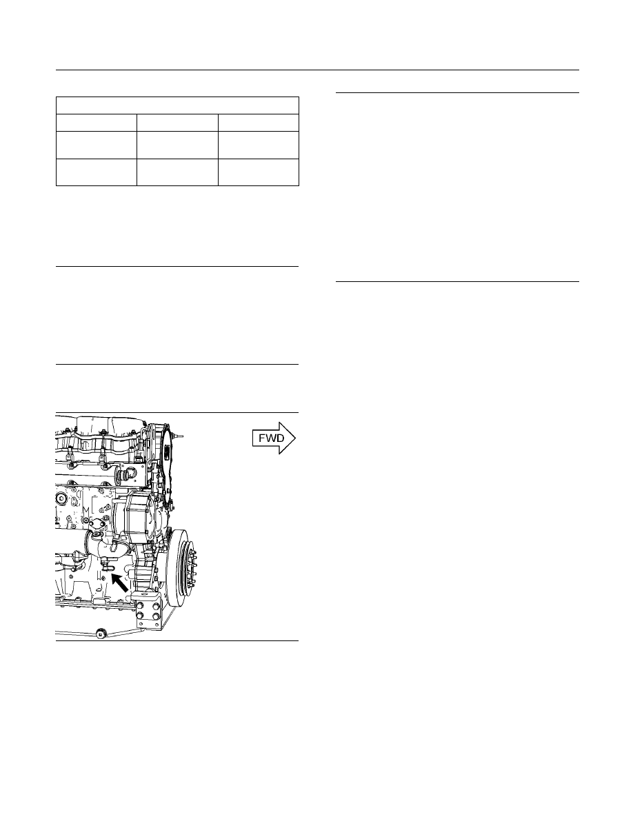
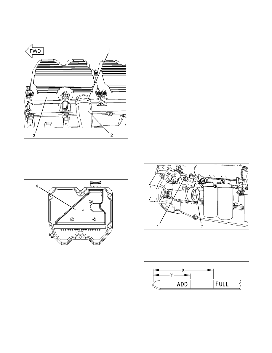
g01942100
Illustration 55
Coolant sampling valve on bottom of the inlet bonnet for the oil
cooler
The coolant sampling valve for the engine coolant is
located on the right side of the engine on the inlet
bonnet for the oil cooler.
NOTICE
Care must be taken to ensure that fluids are contained
during performance of inspection, maintenance, test-
ing, adjusting and repair of the product. Be prepared to
collect the fluid with suitable containers before open-
ing any compartment or disassembling any compo-
nent containing fluids.
Refer to Special Publication, NENG2500, “Caterpillar
Dealer Service Tool Catalog” or refer to Special Pub-
lication, PECJ0003, “Caterpillar Shop Supplies and
Tools Catalog” for tools and supplies suitable to col-
lect and contain fluids on Caterpillar products.
Dispose of all fluids according to local regulations and
mandates.
Obtain the sample of the coolant as close as possible
to the recommended sampling interval. In order
to receive the full effect of S·O·S analysis, you
must establish a consistent trend of data. In order
to establish a pertinent history of data, perform
consistent samplings that are evenly spaced.
Supplies for collecting samples can be obtained from
your Caterpillar dealer.
Use the following guidelines for proper sampling of
the coolant:
•
Complete the information on the label for the
sampling bottle before you begin to take the
samples.
•
Keep the unused sampling bottles stored in plastic
bags.
•
Obtain coolant samples directly from the coolant
sample port. You should not obtain the samples
from any other location.
•
Keep the lids on empty sampling bottles until you
are ready to collect the sample.
•
Place the sample in the mailing tube immediately
after obtaining the sample in order to avoid
contamination.
•
Never collect samples from expansion bottles.
•
Never collect samples from the drain for a system.
Submit the sample for Level 1 analysis.
For additional information about coolant analysis,
see this Operation and Maintenance Manual, “Refill
Capacities and Recommendations” or consult your
Caterpillar dealer.
98
SEBU7689-10
Maintenance Section
Cooling System Coolant Sample (Level 2) - Obtain
i01987714
Cooling System Coolant
Sample (Level 2) - Obtain
SMCS Code: 1350-008; 1395-008; 1395-554; 7542
NOTICE
Always use a designated pump for oil sampling, and
use a separate designated pump for coolant sampling.
Using the same pump for both types of samples may
contaminate the samples that are being drawn. This
contaminate may cause a false analysis and an incor-
rect interpretation that could lead to concerns by both
dealers and customers.
Refer to Operation and Maintenance Manual,
“Cooling System Coolant Sample (Level 1) - Obtain”
for the guidelines for proper sampling of the coolant.
Submit the sample for Level 2 analysis.
For additional information about coolant
analysis, see Special Publication, SEBU6251,
“Caterpillar Commercial Diesel Engines Fluids
Recommendations” or consult your Caterpillar dealer.
i03509177
Cooling System Supplemental
Coolant Additive (SCA) -
Test/Add
SMCS Code: 1352-045; 1395-081
Note: This maintenance is NOT required for
cooling systems that are filled with Extended Life
Coolant.
Cooling system coolant additive contains alkali.
To help prevent personal injury, avoid contact with
the skin and eyes. Do not drink cooling system
coolant additive.
NOTICE
Excessive supplemental coolant additive concentra-
tion can form deposits on the higher temperature sur-
faces of the cooling system, reducing the engine's
heat transfer characteristics. Reduced heat transfer
could cause cracking of the cylinder head and other
high temperature components.
Excessive supplemental coolant additive concentra-
tion could also result in blockage of the heat exchang-
er, overheating, and/or accelerated wear of the water
pump seal.
Do not exceed the recommended amount of supple-
mental coolant additive concentration.
NOTICE
Care must be taken to ensure that fluids are contained
during performance of inspection, maintenance, test-
ing, adjusting and repair of the product. Be prepared to
collect the fluid with suitable containers before open-
ing any compartment or disassembling any compo-
nent containing fluids.
Refer to Special Publication, NENG2500, “Caterpillar
Dealer Service Tool Catalog” and to Special Publica-
tion, GECJ0003, “Cat Shop Supplies and Tools” for
tools and supplies suitable to collect and contain flu-
ids on Caterpillar products.
Dispose of all fluids according to applicable regula-
tions and mandates.
Note: Caterpillar recommends an S·O·S coolant
analysis (Level 1).
Cooling Systems that Use
Conventional Coolant
Test the Concentration of the SCA
NOTICE
Do not exceed the recommended six percent supple-
mental coolant additive concentration.
Test the concentration of the SCA with the
4C-9301
Coolant Conditioner Test Kit.

SEBU7689-10
99
Maintenance Section
Cooling System Water Temperature Regulator - Replace
Add the SCA, If Necessary
Pressurized System: Hot coolant can cause seri-
ous burns. To open the cooling system filler cap,
stop the engine and wait until the cooling system
components are cool. Loosen the cooling system
pressure cap slowly in order to relieve the pres-
sure.
1. Remove the cooling system filler cap slowly.
2. If necessary, drain some coolant in order to allow
space for the addition of the SCA.
3. Add the proper amount of SCA. For the
proper amount of SCA, refer to this Operation
and Maintenance Manual, “Refill Capacities
and Recommendations” topic. The proper
concentration of SCA depends on the type of
coolant that is used. For the proper concentration
of SCA, refer to Special Publication, SEBU6251,
“Caterpillar Commercial Diesel Engine Fluids
Recommendations”.
4. Clean the cooling system filler cap. Install the
cooling system filler cap.
i03645060
Cooling System Water
Temperature Regulator -
Replace
SMCS Code: 1355-510
Replace the water temperature regulator before
the water temperature regulator fails. This is a
recommended preventive maintenance practice.
Replacing the water temperature regulator reduces
the chances for unscheduled downtime. Refer to this
Operation and Maintenance Manual, “Maintenance
Interval Schedule” for the proper maintenance
interval.
A water temperature regulator that fails in a
partially opened position can cause overheating or
overcooling of the engine.
A water temperature regulator that fails in the closed
position can cause excessive overheating. Excessive
overheating could result in cracking of the cylinder
head or piston seizure problems.
A water temperature regulator that fails in the open
position will cause the engine operating temperature
to be too low during partial load operation. Low
engine operating temperatures during partial loads
could cause an excessive carbon buildup inside the
cylinders. This excessive carbon buildup could result
in an accelerated wear of the piston rings and wear
of the cylinder liner.
NOTICE
Failure to replace your water temperature regulator
on a regularly scheduled basis could cause severe
engine damage.
Caterpillar engines incorporate a shunt design cooling
system and require operating the engine with a water
temperature regulator installed.
If the water temperature regulator is installed incor-
rectly, the engine may overheat, causing cylinder head
damage. Ensure that the new water temperature reg-
ulator is installed in the original position. Ensure that
the water temperature regulator vent hole is open.
Do not use liquid gasket material on the gasket or
cylinder head surface.
Refer to two articles in the Disassembly and
Assembly Manual, “Water Temperature Regulators
- Remove and Water Temperature Regulators -
Install” for the replacement procedure of the water
temperature regulator, or consult your Caterpillar
dealer.
Note: If only the water temperature regulators are
replaced, drain the coolant from the cooling system to
a level that is below the water temperature regulator
housing.
i03175962
Crankshaft Vibration Damper
- Inspect
SMCS Code: 1205-040
Damage to the crankshaft vibration damper or failure
of the crankshaft vibration damper can increase
torsional vibrations. This can result in damage to
the crankshaft and to other engine components. A
deteriorating damper can cause excessive gear train
noise at variable points in the speed range.
The damper is mounted to the crankshaft which is
located behind the belt guard on the front of the
engine.
100
SEBU7689-10
Maintenance Section
Engine - Clean
g01134779
Illustration 56
Viscous vibration damper
Typical example
(1) Crankshaft pulley
(2) Weight
(3) Case
Inspection
Inspect the damper for the following conditions:
•
The damper is dented, cracked, or fluid is leaking
from the damper.
•
The paint on the damper is discolored from
excessive heat.
•
The damper is bent.
•
The bolt holes are worn or there is a loose fit for
the bolts.
•
The engine has had a crankshaft failure due to
torsional forces.
Replace the damper if any of these conditions exist.
Removal and Installation
Refer to this Operation and Maintenance Manual,
“Belts - Inspect/Adjust/Replace” for information
on removing and on installing the belt. Refer to
the Disassembly and Assembly Manual, “Vibration
Damper and Pulley - Remove and Install” for
information on removing and installing the damper.
i01646701
Engine - Clean
SMCS Code: 1000-070
Personal injury or death can result from high volt-
age.
Moisture can create paths of electrical conductiv-
ity.
Make sure that the electrical system is OFF. Lock
out the starting controls and tag the controls “DO
NOT OPERATE”.
NOTICE
Accumulated grease and oil on an engine is a fire haz-
ard. Keep the engine clean. Remove debris and fluid
spills whenever a significant quantity accumulates on
the engine.
Periodic cleaning of the engine is recommended.
Steam cleaning the engine will remove accumulated
oil and grease. A clean engine provides the following
benefits:
•
Easy detection of fluid leaks
•
Maximum heat transfer characteristics
•
Ease of maintenance
Note: Caution must be used in order to prevent
electrical components from being damaged by
excessive water when you clean the engine. Avoid
electrical components such as the alternator, the
starter, and the ECM.
i01756656
Engine Air Cleaner Element -
Clean/Replace
SMCS Code: 1054-070; 1054-510
NOTICE
Never run the engine without an air cleaner element
installed. Never run the engine with a damaged air
cleaner element. Do not use air cleaner elements with
damaged pleats, gaskets or seals. Dirt entering the
engine causes premature wear and damage to engine
components. Air cleaner elements help to prevent air-
borne debris from entering the air inlet.
SEBU7689-10
101
Maintenance Section
Engine Air Cleaner Element - Clean/Replace
Type 1
Note: Use the
102-9720 Cleaning Kit. This product
contains the detergent and oil that is made specifically
for the maintenance of the air cleaner elements.
g00898593
Illustration 57
(1) Air cleaner element
Note: This type of air cleaner element should be
replaced after three cleanings.
1. Remove the air cleaner element (1). Tap the air
cleaner element in order to dislodge dirt particles.
Gently brush the air cleaner element with a soft
bristle brush.
NOTICE
Do not use gasoline, steam, caustic or unapproved
detergents, or parts cleaning solvents. Do not use high
pressure water or air to clean the air cleaner element.
Any of those liquids or methods can cause air cleaner
element damage.
2. Spray the air cleaner element with the cleaning
solution. Allow the air cleaner element to stand
for 10 minutes.
3. Rinse the air cleaner element with low water
pressure. The maximum water pressure for this
procedure is 275 kPa (40 psi). Tap water is
acceptable. Start to rinse the air cleaner element
from the clean side (inside). Next, clean the dirty
side (outside) in order to flush out dirt. Inspect the
air cleaner element for tears and/or holes after
the air cleaner element is cleaned. Do not reuse
damaged air cleaner elements.
NOTICE
Do not use compressed air, open flame, or hot air to
dry the air cleaner element. Excess heat shrinks cot-
ton fiber, and compressed air may blow holes in the
material. Allow the air cleaner element to air dry.
4. Shake excess water off the air cleaner element ,
and allow the air cleaner element to air dry. Drying
the air cleaner element in the sun speeds the
process.
NOTICE
Do not use transmission fluid, engine oil, diesel fuel,
or other lubricant to oil the air cleaner element. The
air cleaner element can not function correctly if im-
proper oil is used. Never operate an engine with a
dry air cleaner element. The air cleaner element can
not function correctly without oil. Always saturate the
clean air cleaner element with the recommended oil.
5. The dry air cleaner element should be oiled before
installation. Apply small amounts of oil across the
top of each pleat. Allow the oil to soak into the air
cleaner element for 20 minutes. Oil any remaining
“white” spots.
6. Inspect the housing and the clamp for air cleaner
element (1). Install the clean, oiled air cleaner
element. Replace the housing and the clamp, if
necessary. Refer to Specifications, SENR3130,
“Torque Specifications” for the proper torque of
the clamp.
Type 2
g00898590
Illustration 58
1. Disconnect latches (1).
2. Remove cover (2).
3. Remove the air cleaner element.
Note: This type of air cleaner element may be
cleaned up to six times.
4. Refer to Guideline for Reusable Parts and Salvage
Operations, SEBF8062 for cleaning instructions or
replace the air cleaner element.
5. Install the air cleaner element.
102
SEBU7689-10
Maintenance Section
Engine Air Cleaner Service Indicator - Inspect
6. Install cover (2).
7. Fasten cover (2) with latches (1).
i03612108
Engine Air Cleaner Service
Indicator - Inspect
SMCS Code: 7452-040
A service indicator may be mounted on the air
cleaner element or in a remote location.
g01640336
Illustration 59
Typical air cleaner service indicator
Some engines may be equipped with a different
service indicator.
Observe the service indicator. Clean the air cleaner
element or replace the air cleaner element when the
following conditions occur:
•
The yellow diaphragm enters the red zone.
•
The red piston locks in the visible position.
•
The air restriction reaches 6 kPa (25 inches of H
2
O).
Test the Service Indicator
Service indicators are important instruments.
•
Check for ease of resetting. The service indicator
should reset in less than three pushes.
•
Check the movement of the yellow core when the
engine is accelerated to the engine rated rpm.
The yellow core should latch approximately at the
greatest vacuum that is attained.
If the service indicator does not reset easily, or if the
yellow core does not latch at the greatest vacuum,
the service indicator should be replaced. If the new
service indicator will not reset, the fitting for the
service indicator may be plugged.
g00351792
Illustration 60
Porous filter
A porous filter is part of a fitting that is used for
mounting of the service indicator. Inspect the filter
for cleanliness. Clean the filter, if necessary. Use
compressed air or a clean, nonflammable solvent.
The service indicator may need to be replaced
frequently in environments that are severely dusty, if
necessary. Replace the service indicator annually
regardless of the operating conditions. Replace the
service indicator when the engine is overhauled, and
whenever major engine components are replaced.
Note: When a new service indicator is installed,
excessive force may crack the top of the service
indicator. Tighten the service indicator to a torque
of 2 N·m (18 lb in).
i02751871
Engine Crankcase Breather -
Clean
SMCS Code: 1317-070
NOTICE
Perform this maintenance with the engine stopped.
If the crankcase breather is not maintained on a
regular basis, the crankcase breather will become
plugged. A plugged crankcase breather will cause
excessive crankcase pressure that may cause
crankshaft seal leakage.
SEBU7689-10
103
Maintenance Section
Engine Mounts - Inspect
g01377732
Illustration 61
1. Loosen hose clamp (1) and remove breather hose
(2) from valve cover (3).
2. Remove valve cover (3). Refer to the Disassembly
and Assembly Manual.
g01377736
Illustration 62
3. Wash breather (4) in solvent that is clean and
nonflammable. Allow the breather to dry before
installation.
4. Install the valve cover. Refer to the Disassembly
and Assembly Manual.
5. Install the breather hose on the valve cover. Install
the hose clamp.
i02456872
Engine Mounts - Inspect
SMCS Code: 1152-040
Inspect the engine mounts for deterioration and for
proper bolt torque. Engine vibration can be caused
by the following conditions:
•
Improper mounting of the engine
•
Deterioration of the engine mounts
Any engine mount that shows deterioration should be
replaced. Refer to Special Publication, SENR3130,
“Torque Specifications” for the recommended
torques. Refer to the OEM recommendations for
more information.
i02703852
Engine Oil Level - Check
SMCS Code: 1348-535-FLV
g01356472
Illustration 63
Right hand service shown
1. Stop the engine and allow the engine oil to drain
into the crankcase for approximately ten minutes.
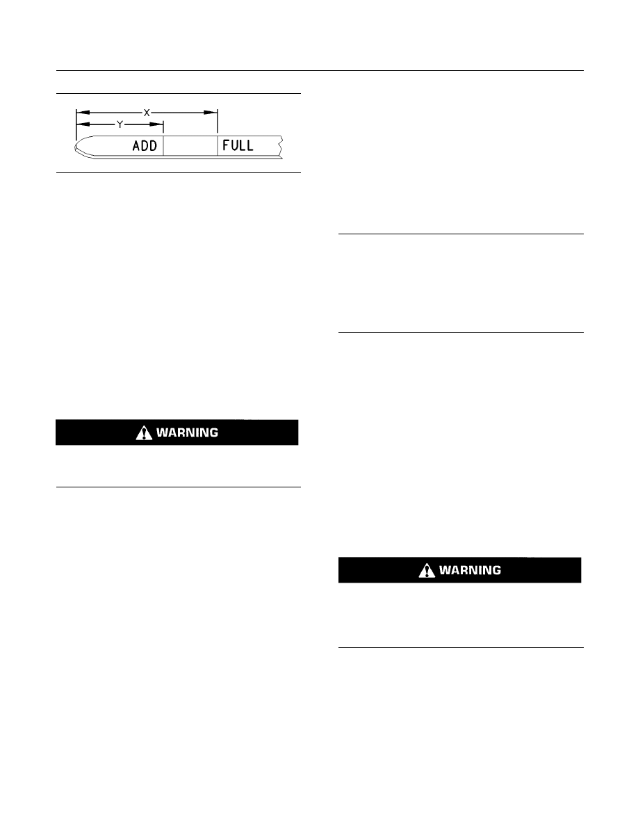
g00110310
Illustration 64
Oil level gauge
(Y) “ADD” mark
(X) “FULL” mark

104
SEBU7689-10
Maintenance Section
Engine Oil Level Gauge - Calibrate
2. Check the engine oil. Maintain the engine oil level
between “ADD” mark (Y) and “FULL” mark (X) on
engine oil level gauge (2). Do not fill the crankcase
above “FULL” mark (X).
NOTICE
Operating your engine when the oil level is above the
“FULL” mark could cause your crankshaft to dip into
the oil. The air bubbles created from the crankshaft
dipping into the oil reduces the oil's lubricating char-
acteristics and could result in the loss of power.
3. Remove engine oil filler cap (1) and add oil, if
necessary. Clean the engine oil filler cap. Reinstall
the engine oil filler cap.
i02703804
Engine Oil Level Gauge -
Calibrate
SMCS Code: 1326-524
The engine is shipped with an engine oil level gauge
that is not marked. The engine oil level gauge is
not marked because the following features can be
different for each engine:
•
Angle of the installation
•
Side for service
The engine oil level gauge must be calibrated after
the engine is installed in the vessel.
Note: The engine may be equipped with auxiliary
engine oil filters. The extra filters require more engine
oil than the standard amounts. Refer to the OEM
specifications.
Use the following procedure in order to calibrate and
mark the engine oil level gauge.
1. Ensure that the engine is properly aligned and that
the engine is in the design trim. The engine must
be installed properly in the vessel.
Note: If the engine has oil in the crankcase, skip step
2 and proceed to step 3.
2. If there is no oil in the engine, use information in
this Operation and Maintenance Manual, “Refill
Capacities and Recommendations” in order to
select the correct oil for the engine. Add engine oil
to the crankcase by using the procedure in this
Operation and Maintenance Manual, “Engine Oil
and Filter - Change ”. Choose the appropriate
amount of oil from the following types of sumps:
•
Standard Oil Sump: Fill the crankcase with
45.4 L (48 qt) of the recommended oil.
•
Deep Oil Sump: Fill the crankcase with 64.3 L
(68 qt) of the recommended oil.
Clean the engine oil level gauge and install the
engine oil level gauge.
Note: If the engine contains oil, perform steps 3
through 7. Skip steps 3 through 7 if you are filling the
engine with oil for the first time.
3. Operate the engine until normal operating
temperature is achieved. Stop the engine. Drain
the engine oil by using the procedure in this
Operation and Maintenance Manual, “Engine Oil
and Filter - Change ”.
4. Replace the engine oil filter by using the procedure
in this Operation and Maintenance Manual,
“Engine Oil and Filter - Change ”.
5. Clean the engine oil level gauge and install the
engine oil level gauge.
6. Use the information in Operation and Maintenance
Manual, “Refill Capacities and Recommendations”
in order to select the correct oil for the engine.
7. Add engine oil to the crankcase by using the
procedure in this Operation and Maintenance
Manual, “Engine Oil and Filter - Change ”. Choose
the appropriate amount of oil from the following
two sumps:
•
Standard Oil Sump: Fill the crankcase with
45.4 L (48 qt) of the recommended oil.
•
Deep Oil Sump: Fill the crankcase with 64.3 L
(68 qt) of the recommended oil.
8. Start the engine. Ensure that the lubrication
system and the new engine oil filter are filled.
Inspect the lubrication system for leaks.
9. Stop the engine and allow the engine oil to drain
into the engine crankcase for approximately ten
minutes.
10. Check the engine oil level. Use a marking tool in
order to engrave the “ADD” mark (Y) to the correct
location on the gauge assembly.
11. Add 3.8 L (4 qt) of the recommended oil grade
and weight of engine oil to the crankcase. Add this
amount for both standard sumps and deep sumps.
12. Check the engine oil level. Use a marking tool in
order to engrave “FULL” mark (X) onto the correct
location on the gauge assembly.
SEBU7689-10
105
Maintenance Section
Engine Oil Sample - Obtain
g00110310
Illustration 65
Oil Level Gauge “ADD” mark (Y) and “FULL” mark (X)
i03542996
Engine Oil Sample - Obtain
SMCS Code: 1000-008; 1348-554-SM;
7542-554-OC, SM
In addition to a good preventive maintenance
program, Caterpillar recommends using S·O·S oil
analysis at regularly scheduled intervals in order
to monitor the condition of the engine and the
maintenance requirements of the engine. S·O·S oil
analysis provides infrared analysis, which is required
for determining nitration and oxidation levels.
Obtain the Sample and the Analysis
Hot oil and hot components can cause personal
injury. Do not allow hot oil or hot components to
contact the skin.
Before you take the oil sample, complete the Label,
PEEP5031 for identification of the sample. In order
to help obtain the most accurate analysis, provide
the following information:
•
Engine model
•
Service hours on the engine
•
The number of hours that have accumulated since
the last oil change
•
The amount of oil that has been added since the
last oil change
To ensure that the sample is representative of the
oil in the crankcase, obtain a warm, well mixed oil
sample.
To avoid contamination of the oil samples, the tools
and the supplies that are used for obtaining oil
samples must be clean.
Caterpillar recommends using the sampling valve
in order to obtain oil samples. The quality and the
consistency of the samples are better when the
sampling valve is used. The location of the sampling
valve allows oil that is flowing under pressure to be
obtained during normal engine operation.
The
169-8373 Fluid Sampling Bottle is
recommended for use with the sampling valve. The
fluid sampling bottle includes the parts that are
needed for obtaining oil samples. Instructions are
also provided.
NOTICE
Always use a designated pump for oil sampling, and
use a separate designated pump for coolant sampling.
Using the same pump for both types of samples may
contaminate the samples that are being drawn. This
contaminate may cause a false analysis and an incor-
rect interpretation that could lead to concerns by both
dealers and customers.
If the engine is not equipped with a sampling valve,
use the
1U-5718 Vacuum Pump. The pump is
designed to accept sampling bottles. Disposable
tubing must be attached to the pump for insertion
into the sump.
For instructions, see Special Publication, PEgj0047,
“How To Take A Good S·O·S Oil Sample”. Consult
your Caterpillar dealer for complete information and
assistance in establishing an S·O·S program for your
engine.
i02683617
Engine Oil and Filter - Change
SMCS Code: 1318-510; 1348-044
Hot oil and components can cause personal in-
jury.
Do not allow hot oil or components to contact
skin.
If the engine is equipped with duplex oil filters, the
engine oil filter elements can be changed while the
engine is in operation. This is useful if the oil filter
elements require more frequent replacement than the
engine oil. Refer to “Replacing the Engine Oil Filters
During Engine Operation”.
The oil change interval can be affected by several
factors:
•
Air/fuel ratio
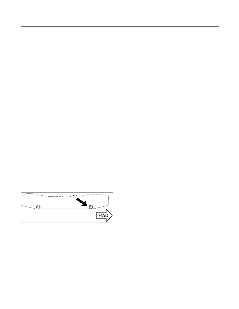
106
SEBU7689-10
Maintenance Section
Engine Oil and Filter - Change
•
Ambient air conditions
•
Engine application
•
Fuel type
•
Oil type
•
Size of the oil sump
The S·O·S oil analysis program analyzes used oil in
order to determine if the oil change interval is suitable
for your specific engine.
Drain the Oil
Do not drain the oil when the engine is cold. As the
oil cools, waste particles settle on the bottom of the
oil pan. The waste particles are not removed when
the cold oil is drained. Drain the crankcase when the
oil is warm. This method allows proper draining of the
waste particles that are suspended in the oil.
Failure to follow this recommended procedure will
allow the waste particles to be recirculated through
the engine lubrication system with the new oil.
1. After the engine has been operated at normal
operating temperature, STOP the engine.
2. Drain the oil according to the equipment on the
engine.
Note: Drain the oil into a suitable container. DO NOT
drain the oil into the bilge sump. Dispose of the oil
according to local regulations.
g01348195
Illustration 66
Oil drain plug
Note: If a suction device is used in order to remove
the oil from the oil pan, ensure that the suction device
is clean. This will prevent dirt from entering into the
oil pan. Be careful not to strike the engine oil suction
tubes or the piston cooling jets.
a. If the engine does not have a drain valve or a
pump, remove an oil drain plug. Allow the oil to
drain. After the oil has drained, clean the drain
plug and clean the fitting for the drain plug.
Install the drain plug. Tighten the drain plug to
70 ± 15 N·m (52 ± 11 lb ft).
b. If the engine has an oil drain valve, open the
valve. After the oil has drained, close the valve.
c. If the engine has a pump for removing dirty oil,
connect a hose to the outlet of the pump. Place
the hose in a suitable container. Open the valve
for the drain line. The two marks on the valve
must be turned so that one mark points to the
pump and the second mark points to the drain
line. Operate the pump until the crankcase
is empty. Close the valve to the drain line.
Disconnect the hose.
d. If the oil drain valve has a “quick connect”
coupling, attach the coupling. Open the drain
valve in order to drain the crankcase. After
the oil has drained, close the drain valve.
Disconnect the coupling.
3. Replace the engine oil filter elements before filling
the crankcase with new oil.
Replace the Oil Filter Elements
Replace the engine oil filters when any of the
following conditions occur:
•
Every oil change
•
The engine oil filter differential pressure reaches
103 kPa (15 psi).
•
The oil filter elements have been used for 1000
service hours.
Note: Do not attempt to clean the used oil filters.
Used oil filters will retain waste particles. The used oil
filters would not filter the oil properly.
Service tools are available to aid in the service of oil
filters. Consult your Caterpillar dealer for the part
names and the part numbers. Follow the instructions
that are supplied with the service tools. If the service
tools are not used, perform the following appropriate
procedure.
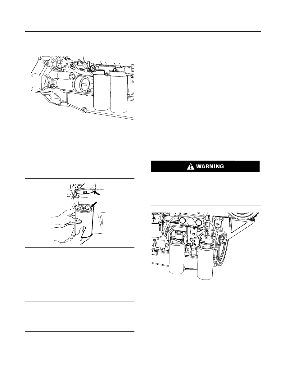
SEBU7689-10
107
Maintenance Section
Engine Oil and Filter - Change
Replacing the Engine Oil Filters With the
Engine Stopped (Standard Oil Filters)
g01356351
Illustration 67
Standard Oil Filters
Right hand service
Perform the following procedure after the oil has
been drained.
1. Remove used oil filters and properly discard the
used oil filters.
g00103713
Illustration 68
Typical filter mounting base and filter gasket
2. Clean the sealing surface of the filter mounting
base. Make sure that the former oil filter gaskets
are removed.
3. Apply a thin film of clean engine oil to the seal of
each new filter gasket.
NOTICE
Do not fill the oil filters with oil before installing them.
This oil would not be filtered and could be contaminat-
ed. Contaminated oil can cause accelerated wear to
engine components.
4. Install the filters by hand. Tighten each filter until
the sealing surface contacts the base. Note the
position of the index marks on each filter in relation
to a fixed point on the filter base.
Note: Caterpillar filters have rotation index marks
that are spaced 90° or 1/4 of a turn away from each
other. When you tighten the filters, use the rotation
index marks as a guide.
5. Tighten each filter according to the instructions
that are printed on the filter.
Note: You may need to use a Caterpillar strap
wrench, or another suitable tool, in order to turn
the filters to the amount that is required for final
installation. Make sure that the installation tool does
not damage the filters. Do not overtighten the oil filter.
Replacing the Engine Oil Filters During
Engine Operation (Duplex Oil Filter
System Only)
This filter contains hot, pressurized oil that can
cause burns and fire hazards, which may result
in bodily injury or death. Follow the instructions
given in this Operation and Maintenance Manual
and stop the engine if rapid air movement exists
to blow the oil.
g01356340
Illustration 69
Duplex Oil Filter System
Left hand service
If the engine is equipped with duplex oil filters, the
engine oil filter elements can be changed while the
engine is in operation. This is useful if the oil filter
elements require more frequent replacement than
the engine oil.
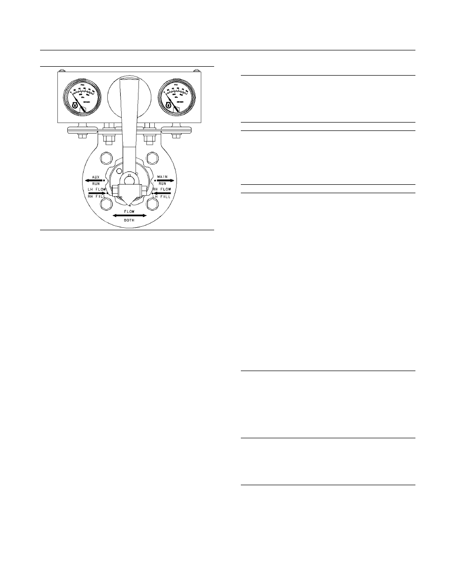
108
SEBU7689-10
Maintenance Section
Engine Oil and Filter - Change
g01034883
Illustration 70
1. Open the “FILL” valve for a minimum of five
minutes in order to fill the oil filter elements that
will not be serviced. The oil filters that will not be
serviced must be full of engine oil. Close the FILL
valve.
2. Move the control valve to the “AUX RUN” position
in order to change the main oil filter elements.
Move the selector valve to the “MAIN RUN”
position in order to change the auxiliary oil filter
elements.
3. Allow the oil pressure gauge for the oil filter that
is being changed to reach a “ZERO” pressure
reading.
4. Perform Step 1 through Step 5 of “Replacing the
Engine Oil Filters With the Engine Stopped”.
5. Open the “FILL” valve for a minimum of five
minutes in order to fill the new oil filter elements.
6. Close the “FILL” valve. Rotate the control valve
to the “RUN” position for the oil filter that was
serviced.
7. Inspect the oil filters for oil leaks. If any leaks exist,
stop the engine and make any necessary repairs.
8. If the engine oil filters were replaced without
changing the crankcase oil, maintain the oil level
between the “FULL” mark and the “ADD” mark on
the oil level gauge. If necessary, add oil.
Fill the Crankcase
NOTICE
Only use oils that are recommended by Caterpillar.
For the proper oil to use, refer to this Operation and
Maintenance Manual, “Engine Oil” topic (Maintenance
Section).
NOTICE
If the engine is equipped with an auxiliary oil filter
system, extra oil must be added when filling the
crankcase. If equipped with an auxiliary oil filter
system that is not supplied by Caterpillar, follow the
recommendations of the OEM.
NOTICE
Engine damage can occur if the crankcase is filled
above the “FULL” mark on the oil level gauge (dip-
stick).
An overfull crankcase can cause the crankshaft to dip
into the oil. This will reduce the power that is devel-
oped and also force air bubbles into the oil. These
bubbles (foam) can cause the following problems: re-
duction of the oil's ability to lubricate, reduction of oil
pressure, inadequate cooling, oil blowing out of the
crankcase breathers, and excessive oil consumption.
Excessive oil consumption will cause deposits to form
on the pistons and in the combustion chamber. De-
posits in the combustion chamber lead to the following
problems: guttering of the valves, packing of carbon
under the piston rings, and wear of the cylinder liner.
If the oil level is above the “FULL” mark on the oil level
gauge, drain some of the oil immediately.
1. Remove the oil filler cap. Fill the crankcase
through the oil filler tube only. For the amount
of oil and type of oil to use, refer to Operation
and Maintenance Manual, “Refill Capacities and
Recommendations” (Maintenance Section). Clean
the oil filler cap. Install the oil filler cap.
NOTICE
To prevent crankshaft or bearing damage, crank en-
gine with fuel off to fill all filters before starting.
Do Not crank engine for more than 30 seconds.
2. Close the fuel supply line and crank the engine
until the oil pressure gauge indicates 70 kPa
(10 psi). Open the fuel supply line. Allow the
starting motor to cool for two minutes before
cranking again.
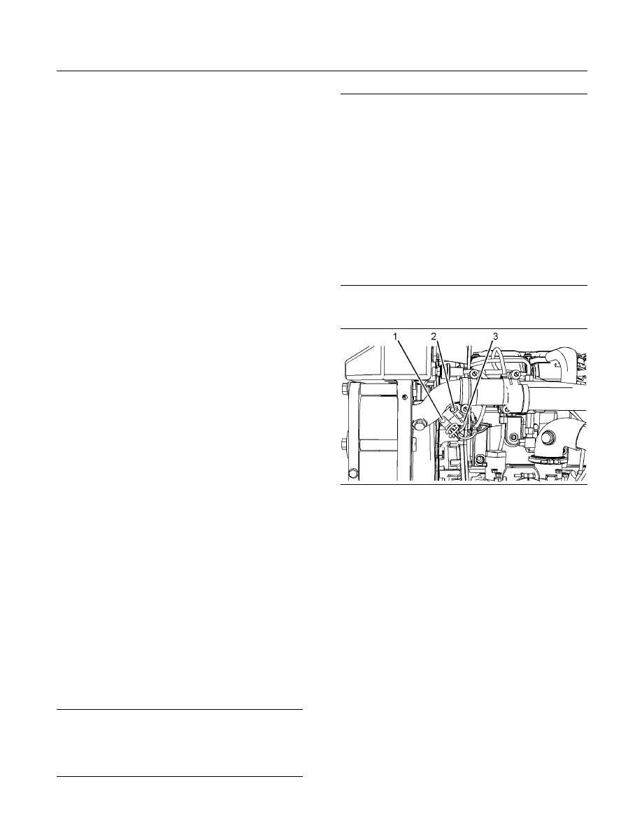
SEBU7689-10
109
Maintenance Section
Engine Speed/Timing Sensor - Clean/Inspect
3. Ensure that the oil level is to the “FULL” mark on
the oil level gauge. Start the engine and operate
the engine at low idle for two minutes. This will
ensure that the lubrication system has oil and that
the oil filters are filled with oil. Inspect the engine
and the oil filters for oil leaks. If any leaks exist,
stop the engine and make any necessary repairs.
4. Stop the engine and allow the oil to drain back into
the sump for a minimum of ten minutes.
5. Remove the oil level gauge and check the oil
level. Maintain the oil level between the “FULL”
mark and the “ADD” mark on the oil level gauge. If
necessary, add oil.
Inspect the Used Oil Filter Elements
Cut the oil filter open with a
175-7546 Oil Filter
Cutter Gp. Break apart the pleats and inspect the oil
filter for metal debris. An excessive amount of metal
debris in the oil filter may indicate early wear or a
pending failure.
Use a magnet to differentiate between the ferrous
metals and the nonferrous metals that are found
in the element. Ferrous metals may indicate wear
on the steel and the cast iron parts of the engine.
Nonferrous metals may indicate wear on the
aluminum parts, the brass parts, or the bronze parts
of the engine. Parts that may be affected include the
following components: main bearings, rod bearings,
turbocharger bearings, and cylinder heads.
Aluminum debris may indicate problems with the
bearings of the front gears. If you find aluminum
debris, inspect the crankshaft vibration damper and
the idler gear bearings.
Due to normal wear and friction, it is not uncommon
to find small amounts of debris in the oil filter element.
If an excessive amount of debris is found in the oil
filter element, consult your Caterpillar dealer in order
to arrange for further oil analysis.
i03572058
Engine Speed/Timing Sensor -
Clean/Inspect
SMCS Code: 1905-040; 1905-070; 1907-040;
1907-070
NOTICE
Keep all parts clean from contaminants.
Contaminants may cause rapid wear and shortened
component life.
NOTICE
Care must be taken to ensure that fluids are contained
during performance of inspection, maintenance, test-
ing, adjusting and repair of the product. Be prepared to
collect the fluid with suitable containers before open-
ing any compartment or disassembling any compo-
nent containing fluids.
Refer to Special Publication, NENG2500, “Caterpillar
Dealer Service Tool Catalog” or refer to Special Pub-
lication, PECJ0003, “Caterpillar Shop Supplies and
Tools Catalog” for tools and supplies suitable to col-
lect and contain fluids on Caterpillar products.
Dispose of all fluids according to local regulations and
mandates.
Camshaft Speed/Timing Sensor
g01368433
Illustration 71
(1) Bolt
(2) Sensor
(3) Harness assembly
Removal Procedure
1. Disconnect the harness assembly.
2. Remove the bolt and the sensor.
3. Remove the O-ring seal from the sensor.
Procedure for Cleaning and Inspecting
Check the condition of the plastic end of the sensor
for wear and for contaminants. Clean the metal
shavings and other debris from the face of the sensor.
Installation Procedure
1. Install a new O-ring seal on the sensor. Lubricate
the O-ring seal with clean engine oil.
2. Position the sensor in the housing and install the
bolt.
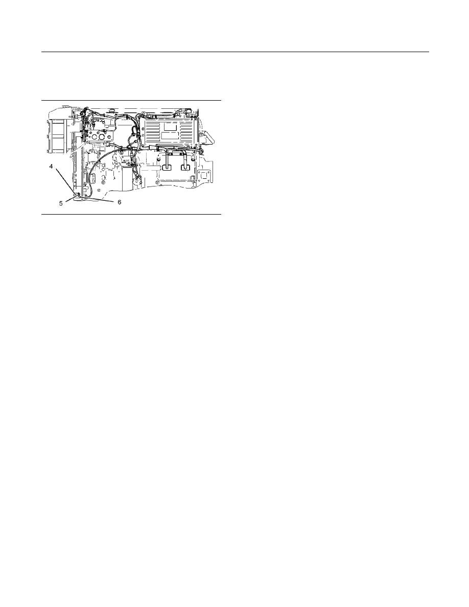
110
SEBU7689-10
Maintenance Section
Engine Storage Procedure - Check
3. Connect the harness assembly.
Crankshaft Speed/Timing Sensor
g01900805
Illustration 72
(4) Bolt
(5) Sensor
(6) Harness
Removal Procedure
1. Disconnect the harness assembly.
2. Remove the bolt and the sensor.
3. Remove the O-ring seal from the sensor.
Procedure for Cleaning and Inspecting
Check the condition of the plastic end of the sensor
for wear and for contaminants. Clean the metal
shavings and other debris from the face of the sensor.
Installation Procedure
1. Install a new O-ring seal on the sensor. Lubricate
the O-ring seal with clean engine oil.
2. Install the position sensor in the front housing and
install the bolt.
3. Connect the harness assembly.
i02703023
Engine Storage Procedure -
Check
SMCS Code: 1000-535
Caterpillar recommends storage procedures and
start-up procedures for all engines that are stored
for more than 1 month. These procedures provide
maximum protection to internal engine components.
Refer to Special Instruction, SEHS9031, “Storage
Procedure For Caterpillar Products” for information
on these procedures.
An extension of the oil change interval to 12 months
is permitted if you follow the required procedures for
storage and start-up. This extension is permitted if the
following intervals in the Operation and Maintenance
Manual, “Maintenance Interval Schedule” have not
been reached:
•
Operating hours
•
Fuel consumption
i00869413
Engine Valve Lash -
Inspect/Adjust
SMCS Code: 1102-025
The initial valve lash adjustment on new engines,
rebuilt engines, or remanufactured engines is
recommended at the first scheduled oil change. The
initial adjustment is necessary due to initial wear of
the valve train components and seating of the valve
train components.
This maintenance is recommended by Caterpillar
as part of a lubrication and preventive maintenance
schedule in order to help provide maximum engine
life.
Adjustment of the Electronic Unit
Injector
Adjust the electronic unit injector (preload) at the
same interval as the valve lash adjustment. The
operation of Caterpillar engines with improper valve
adjustments and with improper adjustments of the
electronic unit injector can reduce engine efficiency.
This reduced efficiency could result in excessive fuel
usage and/or shortened engine component life.

SEBU7689-10
111
Maintenance Section
Engine Valve Rotators - Inspect
NOTICE
Only qualified service personnel should perform this
maintenance. Refer to the Service Manual or your
Caterpillar dealer for the complete valve lash adjust-
ment procedure.
Operation of Caterpillar engines with improper valve
adjustments can reduce engine efficiency. This re-
duced efficiency could result in excessive fuel usage
and/or shortened engine component life.
Ensure that the engine can not be started while
this maintenance is being performed. To help pre-
vent possible injury, do not use the starting motor
to turn the flywheel.
Hot engine components can cause burns. Allow
additional time for the engine to cool before mea-
suring/adjusting valve lash clearance.
i01597115
Engine Valve Rotators - Inspect
SMCS Code: 1109-040
When inspecting the valve rotators, protective
glasses or face shield and protective clothing
must be worn, to help prevent being burned by
hot oil or spray.
Engine valve rotators rotate the valves when the
engine runs. This helps to prevent deposits from
building up on the valves and the valve seats.
Perform the following steps after the engine valve
lash is set, but before the valve covers are installed:
1. Start the engine according to Operation and
Maintenance Manual, “Engine Starting” (Operation
Section) for the procedure.
2. Operate the engine at low idle.
3. Observe the top surface of each valve rotator. The
valve rotators should turn slightly when the valves
close.
NOTICE
A valve rotator which does not operate properly will
accelerate valve face wear and valve seat wear and
shorten valve life. If a damaged rotator is not replaced,
valve face guttering could result and cause pieces of
the valve to fall into the cylinder. This can cause piston
and cylinder head damage.
If a valve fails to rotate, consult your Caterpillar
dealer.
i03534881
Fuel Injector - Inspect/Adjust
SMCS Code: 1290-025
Be sure the engine cannot be started while this
maintenance is being performed. To prevent pos-
sible injury, do not use the starting motor to turn
the flywheel.
Hot engine components can cause burns. Allow
additional time for the engine to cool before mea-
suring/adjusting the unit injectors.
The electronic unit injectors use high voltage. Dis-
connect the unit injector enable circuit connector
in order to prevent personal injury. Do not come
in contact with the injector terminals while the en-
gine is running.
The operation of Caterpillar engines with improper
adjustments of the electronic unit injector can reduce
engine efficiency. This reduced efficiency could result
in excessive fuel usage and/or shortened engine
component life.
Only qualified service personnel should perform
this maintenance. Refer to the Systems Operation,
Testing and Adjusting, “Electronic Unit Injector -
Test” for the test procedure, and Systems Operation,
Testing and Adjusting, “Electronic Unit Injector -
Adjust” for the adjustment procedure for the injectors.
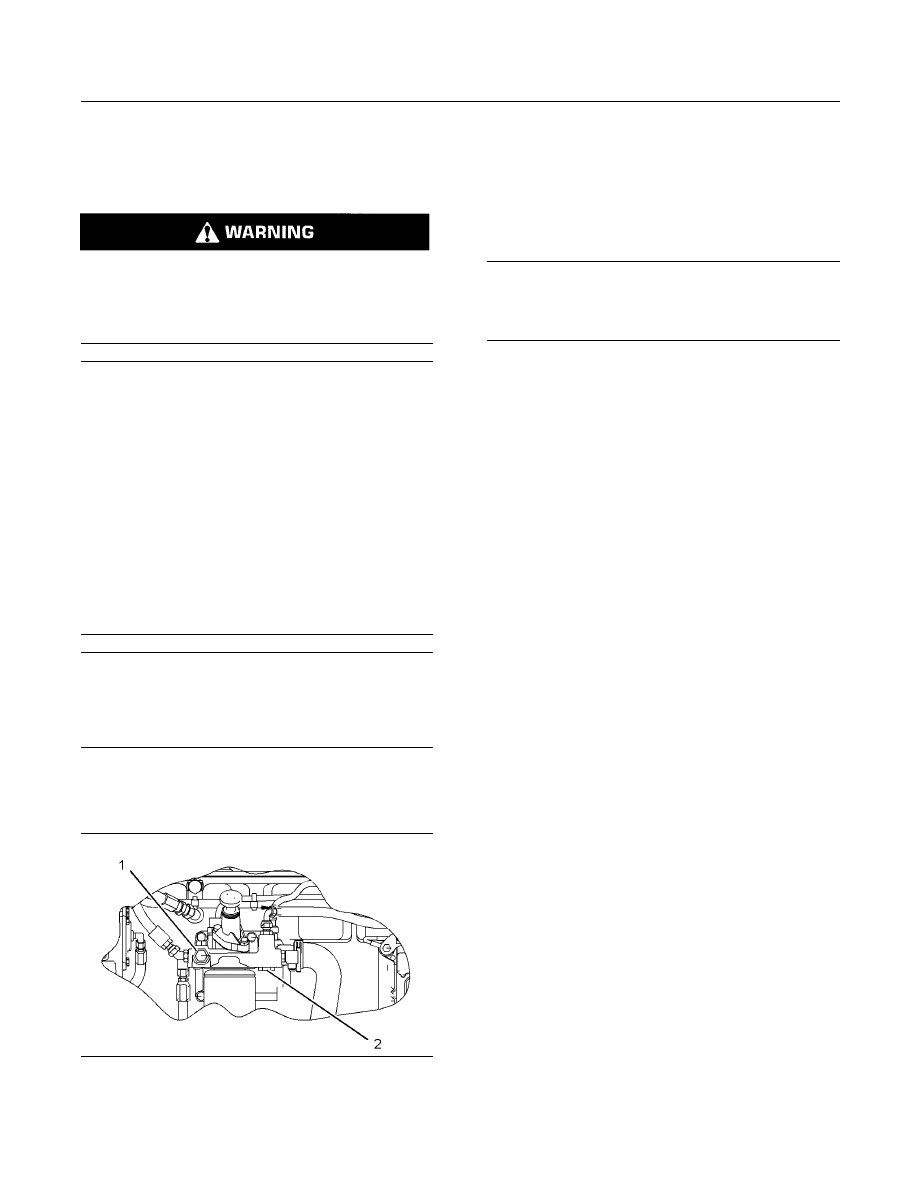
112
SEBU7689-10
Maintenance Section
Fuel System - Prime
i03570039
Fuel System - Prime
SMCS Code: 1258-548
Fuel leaked or spilled onto hot surfaces or elec-
trical components can cause a fire. To help pre-
vent possible injury, turn the start switch off when
changing fuel filters or water separator elements.
Clean up fuel spills immediately.
NOTICE
Care must be taken to ensure that fluids are contained
during performance of inspection, maintenance, test-
ing, adjusting and repair of the product. Be prepared to
collect the fluid with suitable containers before open-
ing any compartment or disassembling any compo-
nent containing fluids.
Refer to Special Publication, NENG2500, “Caterpillar
Dealer Service Tool Catalog” or refer to Special Pub-
lication, PECJ0003, “Caterpillar Shop Supplies and
Tools Catalog” for tools and supplies suitable to col-
lect and contain fluids on Caterpillar products.
Dispose of all fluids according to local regulations and
mandates.
NOTICE
Do not allow dirt to enter the fuel system. Thoroughly
clean the area around a fuel system component that
will be disconnected. Fit a suitable cover over discon-
nected fuel system component.
Note: Refer to this Operation and Maintenance
Manual, “Fuel System Secondary Filter - Replace” for
information on replacing the filter.
g01096972
Illustration 73
Hand priming pump
(1) Air purge screw
(2) Fuel pressure regulating valve
The Secondary Fuel Filter Has
Been Replaced
1. Turn the ignition switch to the “OFF” position.
2. Open the air purge screw for the fuel filter by three
full turns. Do not remove the air purge screw.
NOTICE
Do not crank the engine continuously for more than
30 seconds. Allow the starting motor to cool for two
minutes before cranking the engine again.
3. Start the engine. The engine should start and the
engine should run smoothly. If the engine does
not start after 30 seconds, allow the starting motor
to cool for two minutes before attempting to start
the engine again.
Note: You may use the hand priming pump for the
fuel filter (if equipped) instead of starting the engine
and running the engine.
4. While the engine is running, observe the air purge
screw. When a small drop of fuel appears at the
threads of the air purge screw, close and tighten
air purge screw.
Note: There may be a noticeable change in the
sound of the running engine when the air purge
screw is tightened. The change in the sound of the
engine is normal.
Note: Failure to tighten all fittings could result in
serious fuel leaks.
5. Clean any residual fuel from the engine
components.
The Engine Has Been Run Out of
Fuel
1. Turn the ignition switch to the “OFF” position.
2. Fill the fuel tank(s) with clean diesel fuel.
3. Open the fuel pressure regulating valve by two
and one half turns. The regulating valve is located
in the integral fuel filter base.
Note: Do not remove the regulating valve completely.
Open the valve enough to allow the air that is trapped
in the cylinder head to be purged from the fuel
system.

SEBU7689-10
113
Maintenance Section
Fuel System Primary Filter (Water Separator) Element - Replace
NOTICE
Do not crank the engine continuously for more than
30 seconds. Allow the starting motor to cool for two
minutes before cranking the engine again.
4. Crank the engine for 30 seconds. Use a suitable
container to catch the fuel while you crank the
engine. Allow the starting motor to cool for two
minutes.
Note: You may use the hand priming pump for the
fuel filter (if equipped) instead of cranking the engine.
5. Crank the engine for 30 seconds. Allow the
starting motor to cool for two minutes.
6. Close and tighten the fuel pressure regulating
valve.
7. Crank the engine for 30 seconds. Allow the
starting motor to cool for two minutes.
8. Repeat Step 7 until the engine starts and the
engine runs.
Note: Failure to tighten all fittings could result in
serious fuel leaks.
9. Clean any residual fuel from the engine
components.
The Engine Has Been Rebuilt
1. Turn the ignition switch to the “OFF” position.
2. Fill the fuel tank (s) with clean diesel fuel.
3. Open the the air purge screw for the fuel filter by
three full turns. Do not remove the air purge screw.
4. Open the fuel pressure regulating valve by two
and one half turns. The regulating valve is located
in the integral fuel filter base.
Note: Do not remove the regulating valve completely.
Open the valve enough to allow the air that is trapped
in the cylinder head to be purged from the fuel
system.
NOTICE
Do not crank the engine continuously for more than
30 seconds. Allow the starting motor to cool for two
minutes before cranking the engine again.
5. Crank the engine for 30 seconds. Use a suitable
container to catch the fuel while you crank the
engine. Allow the starting motor to cool for two
minutes.
Note: You may use the hand priming pump for the
fuel filter (if equipped) instead of cranking the engine.
6. Crank the engine for 30 seconds. Allow the
starting motor to cool for two minutes.
7. Close and tighten the air purge screw.
8. Crank the engine for 30 seconds. Allow the
starting motor to cool for two minutes.
9. Close and tighten the fuel pressure regulating
valve.
Note: Failure to tighten all fittings could result in
serious fuel leaks.
10. Crank the engine for 30 seconds. Allow the
starting motor to cool for two minutes.
11. Repeat Step 10 until the engine starts and runs.
12. Clean any residual fuel from the engine
components.
i02049797
Fuel System Primary Filter
(Water Separator) Element -
Replace
SMCS Code: 1260-510-FQ; 1263-510-FQ
Water in the fuel can cause the engine to run rough.
Water in the fuel may cause an electronic unit injector
to fail. If the fuel has been contaminated with water,
the element should be changed before the regularly
scheduled interval.
The primary filter/water separator also provides
filtration in order to help extend the life of the
secondary fuel filter. The element should be changed
regularly. Install a vacuum gauge. Change the
element for the primary filter/water separator if the
pressure is at 50 to 70 kPa (15 to 20 inches Hg).
Replace the Element
Fuel leaked or spilled onto hot surfaces or elec-
trical components can cause a fire. To help pre-
vent possible injury, turn the start switch off when
changing fuel filters or water separator elements.
Clean up fuel spills immediately.
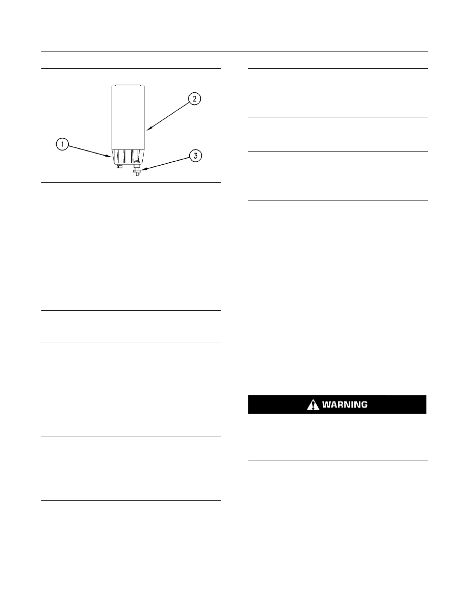
114
SEBU7689-10
Maintenance Section
Fuel System Primary Filter/Water Separator - Drain
g00668636
Illustration 74
(1) Bowl
(2) Element
(3) Drain
1. Stop the engine.
2. Turn the start switch to the “OFF” position.
3. Shut off the fuel tank supply valve to the engine.
4. If the primary fuel filter is equipped with a drain
valve (3), open the drain valve in order to drain any
fuel from the filter case. Close the drain valve (3).
NOTICE
Use a suitable container to catch any fuel that might
spill. Clean up any spilled fuel immediately.
5. Remove the fuel filter bowl (1) and wash the fuel
filter bowl with clean diesel fuel.
6. Remove the fuel filter (2).
7. Clean the gasket sealing surface of the fuel filter
base. Ensure that all of the old gasket is removed.
8. Apply clean diesel fuel to the new fuel filter gasket.
NOTICE
In order to maximize fuel system life and prevent pre-
mature wear out from abrasive particles in the fuel,
use Caterpillar fuel filters.
Consult your Caterpillar dealer for proper part num-
bers.
9. Install the new fuel filter (2). Spin the fuel filter
onto the fuel filter base until the gasket contacts
the base. Use the rotation index marks on the
filters as a guide for proper tightening. Tighten the
filter for an additional 3/4 turn by hand. Do not
overtighten the filter.
NOTICE
Do not fill the fuel filters with fuel before installing them.
The fuel would not be filtered and could be contami-
nated. Contaminated fuel will cause accelerated wear
to fuel system parts.
10. Install the clean fuel filter bowl (1) on the new fuel
filter.
NOTICE
The water separator is under suction during normal
engine operation. Ensure that the vent plug is tight-
ened securely to help prevent air from entering the fu-
el system.
11. Open the fuel tank supply valve.
12. Start the engine and check for leaks. Run the
engine for one minute. Stop the engine and check
the engine for leaks again.
Detection of leaks is very difficult especially if
the engine is running. The primary filter/water
separator is under suction. A leak will allow air to
enter the fuel. The air in the fuel can cause low
power due to aeration of the fuel. If air enters the
fuel, check the components for overtightening or
undertightening.
i02927285
Fuel System Primary
Filter/Water Separator - Drain
SMCS Code: 1260-543; 1263-543
Fuel leaked or spilled onto hot surfaces or elec-
trical components can cause a fire. To help pre-
vent possible injury, turn the start switch off when
changing fuel filters or water separator elements.
Clean up fuel spills immediately.
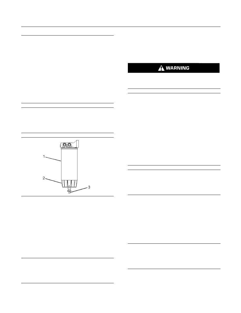
SEBU7689-10
115
Maintenance Section
Fuel System Secondary Filter - Replace
NOTICE
Care must be taken to ensure that fluids are contained
during performance of inspection, maintenance, test-
ing, adjusting and repair of the product. Be prepared to
collect the fluid with suitable containers before open-
ing any compartment or disassembling any compo-
nent containing fluids.
Refer to Special Publication, NENG2500, “Caterpillar
Dealer Service Tool Catalog” for tools and supplies
suitable to collect and contain fluids on Caterpillar
products.
Dispose of all fluids according to local regulations and
mandates.
NOTICE
Do not allow dirt to enter the fuel system. Thoroughly
clean the area around a fuel system component that
will be disconnected. Fit a suitable cover over discon-
nected fuel system component.
g01453091
Illustration 75
(1) Element
(2) Bowl
(3) Drain
Bowl (2) should be monitored daily for signs of water.
If water is present, drain the water from the bowl.
1. Open drain (3). The drain is a self-ventilated drain.
Catch the draining water in a suitable container.
Dispose of the water properly.
2. Close drain (3).
NOTICE
The water separator is under suction during normal
engine operation. Ensure that the drain valve is tight-
ened securely to help prevent air from entering the fuel
system.
i03572801
Fuel System Secondary Filter -
Replace
SMCS Code: 1261-510-SE
Fuel leaked or spilled onto hot surfaces or elec-
trical components can cause a fire. Clean up fuel
spills immediately.
NOTICE
Care must be taken to ensure that fluids are contained
during performance of inspection, maintenance, test-
ing, adjusting and repair of the product. Be prepared to
collect the fluid with suitable containers before open-
ing any compartment or disassembling any compo-
nent containing fluids.
Refer to Special Publication, NENG2500, “Caterpillar
Dealer Service Tool Catalog” or refer to Special Pub-
lication, PECJ0003, “Caterpillar Shop Supplies and
Tools Catalog” for tools and supplies suitable to col-
lect and contain fluids on Caterpillar products.
Dispose of all fluids according to local regulations and
mandates.
NOTICE
Keep all parts clean from contaminants.
Contaminants may cause rapid wear and shortened
component life.
Note: If the engine is equipped with duplex fuel
filters, the fuel filter elements can be replaced while
the engine is in operation. Refer to “Replacing the
Fuel Filter Elements During Engine Operation For
Engines That Are Equipped With Duplex Fuel Filters”.
Replacing the Fuel Filter Elements
with the Engine Stopped
NOTICE
Do not allow dirt to enter the fuel system. Thoroughly
clean the area around a fuel system component that
will be disconnected. Fit a suitable cover over discon-
nected fuel system component.
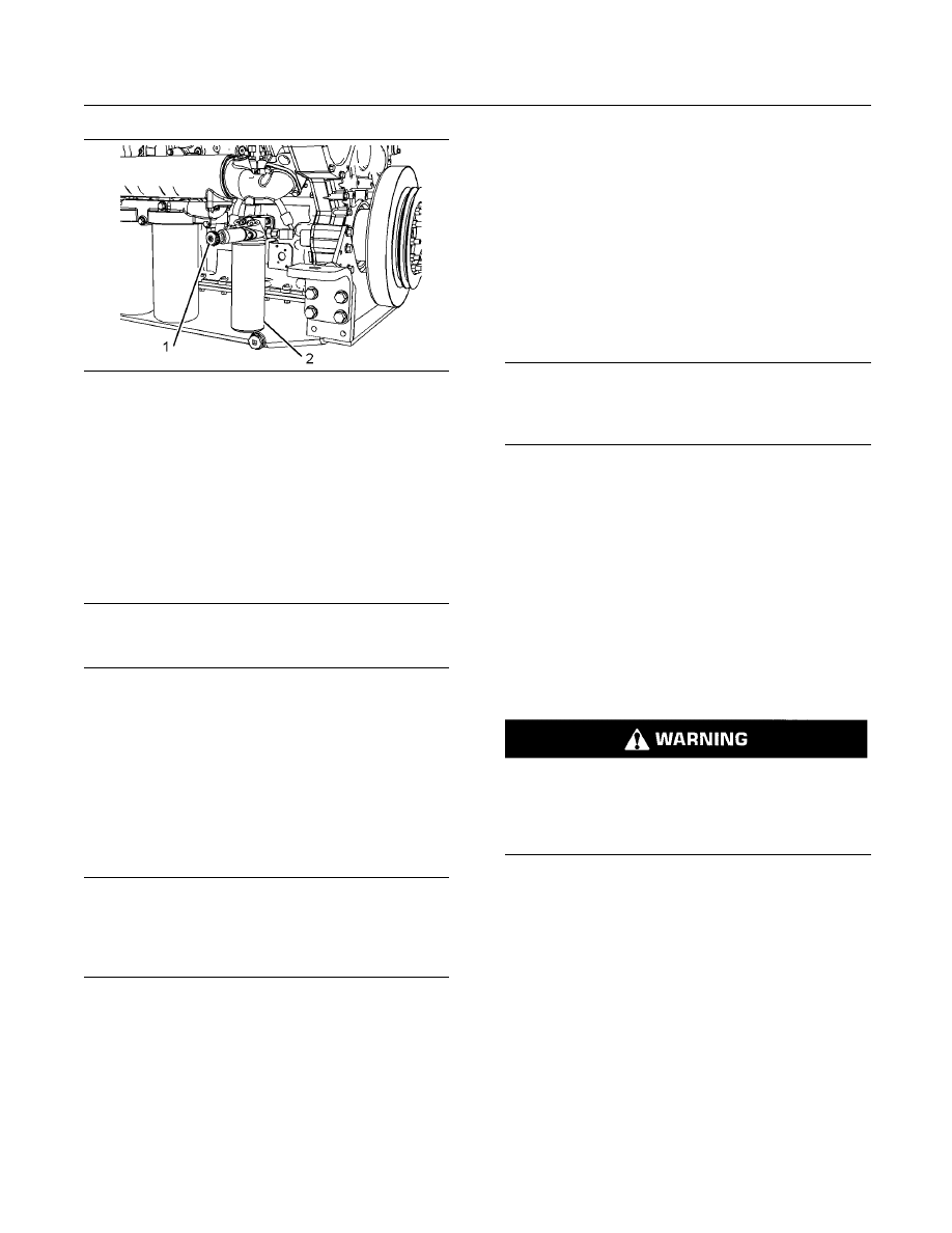
116
SEBU7689-10
Maintenance Section
Fuel System Secondary Filter - Replace
g01902879
Illustration 76
Right hand service
(1) Fuel priming pump
(2) Fuel filter
1. Stop the engine.
2. Turn off the start switch or disconnect the battery
(starting motor) when maintenance is performed
on fuel filters.
3. Shut off the fuel tank supply valve to the engine.
NOTICE
Use a suitable container to catch any fuel that might
spill. Clean up any spilled fuel immediately.
4. Unlock the fuel priming pump in order to relieve
residual pressure in the fuel system.
5. Remove the used fuel filter. Use a cloth or use a
container in order to catch excess fuel.
6. Clean the gasket sealing surface of the fuel filter
base. Ensure that all of the old gasket is removed.
7. Apply clean diesel fuel to the new fuel filter gasket.
NOTICE
Do not fill the secondary fuel filter with fuel before in-
stalling. The fuel would not be filtered and could be
contaminated. Contaminated fuel will cause acceler-
ated wear to fuel system parts.
8. Install the new fuel filter. Tighten the fuel filter until
the gasket contacts the base. Tighten the fuel
filter by hand according to the instructions that are
shown on the fuel filter. Do not overtighten the fuel
filter.
Note: DO NOT remove the plug in the fuel filter base
in order to release the air from the fuel system during
periodic service of the fuel filter. Periodic removal of
the plug will result in increased wear of the threads in
the fuel filter base.
9. Operate the fuel priming pump plunger until a
strong resistance is felt and until the check valve
clicks. This procedure will require considerable
strokes. Lock the fuel priming pump.
10. Open the fuel tank supply valve.
11. Start the engine according to the normal operating
procedures. Immediately increase the engine rpm
between 1000 to 1200 rpm with no load. The
engine will begin to misfire briefly until air from
the fuel filter is purged. No damage to the engine
will occur.
NOTICE
Do not crank the engine continuously for more than
30 seconds. Allow the starting motor to cool for two
minutes before cranking the engine again.
12. If the engine stalls during the purging of the air,
refer to the Operation and Maintenance Manual,
“Fuel System - Prime” for more information.
Replacing the Fuel Filter Elements
During Engine Operation For
Engines That Are Equipped With
Duplex Fuel Filters
If the engine is equipped with duplex fuel filters, the
fuel filters can be replaced while the engine is in
operation.
This filter contains pressurized fuel that can cause
a fire hazard, which may result in bodily injury or
death. Follow the instructions given in this Opera-
tion and Maintenance Manual and stop the engine
if rapid air movement exists to blow the fuel.
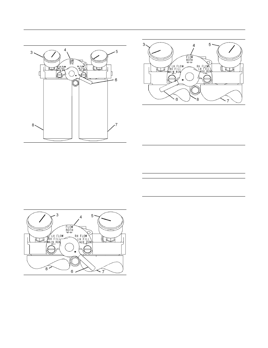
SEBU7689-10
117
Maintenance Section
Fuel System Secondary Filter - Replace
Replacing the Main Fuel Filter
g01902892
Illustration 77
Duplex fuel filters
Engines are shipped from the factory with the control valve in the
MAIN RUN position.
(3) Fuel pressure gauge for the main fuel filter
(4) Plate that shows the position of the valve
(5) Fuel pressure gauge for the auxiliary fuel filter
(6) Control valve
(7) Auxiliary fuel filter
(8) Main fuel filter
Use the following procedure in order to replace the
main fuel filter while the engine is in operation.
g01902917
Illustration 78
1. Move the control valve to the LH FLOW - RH FILL
position as marked on plate. The fuel pressure
gauge for the main fuel filter should indicate
full pressure. The fuel pressure gauge for the
auxiliary fuel filter should indicate slight pressure.
Five minutes may be required in order to fill the
auxiliary fuel filter. The auxiliary fuel filter must
become full of fuel.
g01902918
Illustration 79
2. Move the control valve to the AUX RUN position.
The fuel pressure gauge for the auxiliary fuel filter
should indicate full pressure. The fuel pressure
gauge for the main fuel filter should indicate no
pressure.
NOTICE
Do not allow dirt to enter the fuel system. Thoroughly
clean the area around a fuel system component that
will be disconnected. Fit a suitable cover over discon-
nected fuel system component.
NOTICE
Use a suitable container to catch any fuel that might
spill. Clean up any spilled fuel immediately.
3. Remove the used main fuel filter. Use a cloth or
use a container in order to catch excess fuel.
4. Clean the gasket sealing surface of the main fuel
filter base. Ensure that all of the old gasket is
removed.
5. Apply clean diesel fuel to the new main fuel filter
gasket.
6. Install a new main fuel filter. Tighten the fuel filter
until the gasket contacts the base. Tighten the fuel
filter by hand according to the instructions that are
shown on the fuel filter. Do not overtighten the fuel
filter.
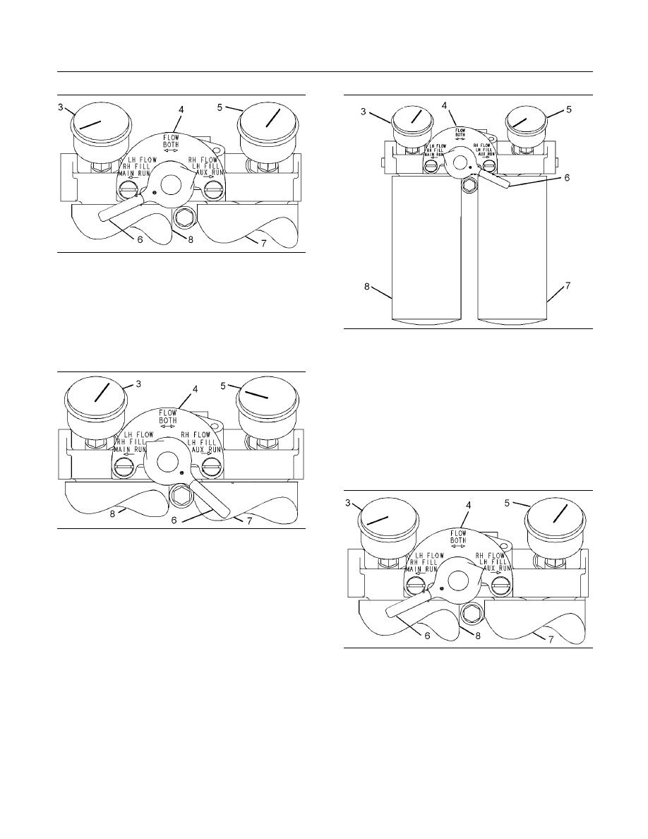
118
SEBU7689-10
Maintenance Section
Fuel System Secondary Filter - Replace
g01902918
Illustration 80
7. Move the control valve to the RH FLOW - LH
FILL position. The fuel pressure gauge for the
auxiliary fuel filter should indicate full pressure.
The fuel pressure gauge for the main fuel filter
should indicate slight pressure. Five minutes may
be required in order to fill the main fuel filter. The
main filter must become full of fuel.
g01902917
Illustration 81
8. Move the control valve to the MAIN RUN position.
The fuel pressure gauge for the main fuel filter
should indicate full pressure. The fuel pressure
gauge for the auxiliary fuel filter should indicate
no pressure.
replacing the Auxiliary Fuel Filter
The procedure for replacing the auxiliary fuel filter is
similar to the procedure for replacing the main fuel
filter.
g01902892
Illustration 82
Duplex fuel filters
The engine is operating with the control valve in the AUX RUN
position.
(3) Fuel pressure gauge for the main fuel filter
(4) Plate that shows the position of the valve
(5) Fuel pressure gauge for the auxiliary fuel filter
(6) Control valve
(7) Auxiliary fuel filter
(8) Main fuel filter
Use the following procedure in order to replace the
auxiliary fuel filter while the engine is in operation.
g01902918
Illustration 83
1. Move the control valve to the RH FLOW - LH FILL
position. The fuel pressure gauge for the auxiliary
fuel filter should indicate full pressure. The fuel
gauge for the main fuel filter should indicate
slight pressure. Five minutes may be required for
filling the main fuel filter. The main fuel filter must
become full of fuel.
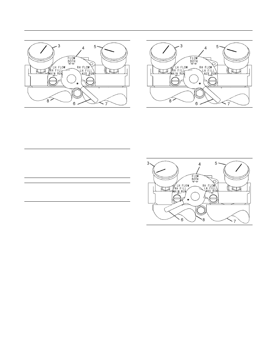
SEBU7689-10
119
Maintenance Section
Fuel System Secondary Filter - Replace
g01902917
Illustration 84
2. Move the control valve to the MAIN RUN position.
The fuel pressure gauge for the main fuel filter
should indicate full pressure. The fuel pressure
gauge for the auxiliary fuel filter should indicate
no pressure.
NOTICE
Do not allow dirt to enter the fuel system. Thoroughly
clean the area around a fuel system component that
will be disconnected. Fit a suitable cover over discon-
nected fuel system component.
NOTICE
Use a suitable container to catch any fuel that might
spill. Clean up any spilled fuel immediately.
3. Remove the used auxiliary fuel filter. Use a cloth
or use a container in order to catch excess fuel.
4. Clean the gasket sealing surface of the auxiliary
fuel filter base. Ensure that all of the old gasket
is removed.
5. Apply clean diesel fuel to the new auxiliary fuel
filter gasket.
6. Install a new auxiliary fuel filter. Tighten the fuel
filter until the gasket contacts the base. Tighten
the fuel filter by hand according to the instructions
that are shown on the fuel filter. Do not overtighten
the fuel filter.
g01902917
Illustration 85
7. Move the control valve to the LH FLOW - RH FILL
position. The fuel pressure gauge for the main
fuel filter should indicate full pressure. The fuel
pressure gauge for the auxiliary fuel filter should
indicate slight pressure. Allow five minutes in
order to fill the auxiliary fuel filter. The auxiliary
fuel filter must become full of fuel.
g01902918
Illustration 86
8. Move the control valve to the AUX RUN position.
The fuel pressure gauge for the auxiliary fuel filter
should indicate full pressure. The fuel pressure
gauge for the main fuel filter should indicate no
pressure.
Move the control valve to the FLOW BOTH position
after both fuel filters are replaced.

120
SEBU7689-10
Maintenance Section
Fuel Tank Water and Sediment - Drain
i03645042
Fuel Tank Water and Sediment
- Drain
SMCS Code: 1273-543-M&S
NOTICE
Care must be taken to ensure that fluids are contained
during performance of inspection, maintenance, test-
ing, adjusting and repair of the product. Be prepared to
collect the fluid with suitable containers before open-
ing any compartment or disassembling any compo-
nent containing fluids.
Refer to Special Publication, NENG2500, “Caterpillar
Dealer Service Tool Catalog” or refer to Special Pub-
lication, PECJ0003, “Caterpillar Shop Supplies and
Tools Catalog” for tools and supplies suitable to col-
lect and contain fluids on Caterpillar products.
Dispose of all fluids according to local regulations and
mandates.
Fuel Tank
Fuel quality is critical to the performance and to the
service life of the engine. Water in the fuel can cause
excessive wear to the fuel system. Condensation
occurs during the heating and cooling of fuel. The
condensation occurs as the fuel passes through the
fuel system and the fuel returns to the fuel tank. This
causes water to accumulate in fuel tanks. Draining
the fuel tank regularly and obtaining fuel from reliable
sources can help to eliminate water in the fuel.
Drain the Water and the Sediment
Fuel tanks should contain some provision for draining
water and draining sediment from the bottom of the
fuel tanks.
Open the drain valve on the bottom of the fuel tank
in order to drain the water and the sediment. Close
the drain valve.
Note: Failure to properly close the drain can allow air
into the system, which could have detrimental results
to performance.
Check the fuel daily. Drain the water and sediment
from the fuel tank after operating the engine or drain
the water and sediment from the fuel tank after the
fuel tank has been filled. Allow five to ten minutes
before performing this procedure.
Fill the fuel tank after operating the engine in
order to drive out moist air. This will help prevent
condensation. Do not fill the tank to the top. The
fuel expands as the fuel gets warm. The tank may
overflow.
Some fuel tanks use supply pipes that allow water
and sediment to settle below the end of the fuel
supply pipe. Some fuel tanks use supply lines that
take fuel directly from the bottom of the tank. If
the engine is equipped with this system, regular
maintenance of the fuel system filter is important.
Fuel Storage Tanks
Drain the water and the sediment from the fuel
storage tank during the following conditions:
•
Weekly
•
Oil change
•
Refill of the tank
This will help prevent water or sediment from being
pumped from the storage tank into the engine fuel
tank. A four micron(c) absolute filter for the breather
vent on the fuel tank is also recommended. Refer
to Special Publication, SENR9620, “Improving Fuel
System Durablity”.
If a bulk storage tank has been refilled or moved
recently, allow adequate time for the sediment to
settle before filling the engine fuel tank. Internal
baffles in the bulk storage tank will also help trap
sediment. Filtering fuel that is pumped from the
storage tank helps to ensure the quality of the fuel.
When possible, water separators should be used.
SEBU7689-10
121
Maintenance Section
Heat Exchanger - Inspect
i02683693
Heat Exchanger - Inspect
SMCS Code: 1379-040
Personal injury can result from hot coolant, steam
and alkali.
At operating temperature, engine coolant is hot
and under pressure. The heat exchanger and all
lines to heaters or the engine contain hot coolant
or steam. Any contact can cause severe burns.
Remove the filler cap slowly to relieve pressure
only when the engine is stopped and the filler cap
for the heat exchanger is cool enough to touch
with your bare hand.
Cooling System Conditioner contains alkali. Avoid
contact with skin and eyes.
NOTICE
Keep all parts clean from contaminants.
Contaminants may cause rapid wear and shortened
component life.
NOTICE
Care must be taken to ensure that fluids are contained
during performance of inspection, maintenance, test-
ing, adjusting and repair of the product. Be prepared to
collect the fluid with suitable containers before open-
ing any compartment or disassembling any compo-
nent containing fluids.
Refer to Special Publication, NENG2500, “Caterpillar
Dealer Service Tool Catalog” for tools and supplies
suitable to collect and contain fluids on Caterpillar
products.
Dispose of all fluids according to local regulations and
mandates.
Plate Type Heat Exchanger
The interval for the maintenance of the plate type heat
exchanger depends on the operating environment of
the vessel and on the operating time. The sea water
that is circulated through the heat exchanger and the
amount of operating time of the vessel affects the
following items:
•
Cleanliness of the heat exchanger plates
•
Effectiveness of the heat exchanger system
Operating in water that contains the following will
adversely affect the heat exchanger system: silt,
sediment, salt, and algae. In addition, intermittent use
of the vessel will adversely affect the heat exchanger
system.
The following items indicate that the heat exchanger
may require cleaning:
•
Increased coolant temperature
•
Engine overheating
•
Excessive pressure drop between the water inlet
and the water outlet
An operator that is familiar with the normal operating
temperature of the coolant can determine when
the coolant temperature is out of the normal range.
Inspection of the heat exchanger and maintenance
of the heat exchanger are required if the engine is
overheating.
Your Caterpillar dealer has the equipment and the
personnel in order to measure the pressure drop
across the heat exchanger.
Consult your Caterpillar dealer or refer to the
Service Manual for service information for the heat
exchanger.
Cleaning the Plate Type Heat Exchanger
Refer to the Disassembly and Assembly Manual
for the engine. The heat exchanger must be
disassembled in order to be cleaned. The
Disassembly and Assembly Manual will contain
instructions for cleaning the heat exchanger prior to
reassembly. The following general guidelines are for
cleaning a plate type heat exchanger. Refer to Table
15 for types of cleaners.
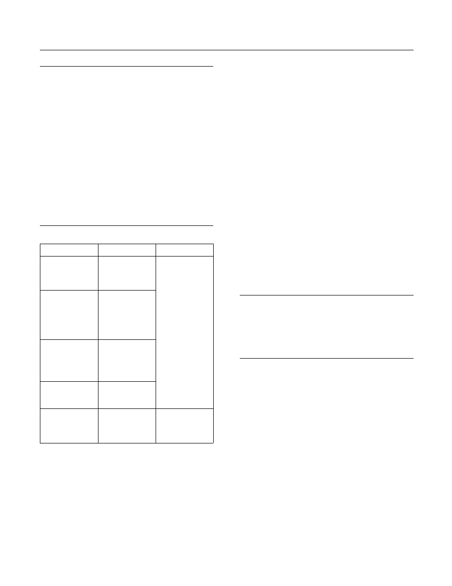
122
SEBU7689-10
Maintenance Section
Hoses and Clamps - Inspect/Replace
NOTICE
Do not use hydrochloric acid to clean stainless steel
plates.
Do not use hydrofluoric acid to clean titanium plates.
Water that contains more than 300 ppm of chlorine
should not be used to prepare cleaning solutions.
Do not use Ketones such as Acetone and Methyle-
tyketone.
Do not use esters such as Ethylacetate and Butylac-
etate.
Do not use Halogenated hydrocarbons such as
Chlorothene and Carbon Tetrachloride
Do not use Aromatics such as Benzene and Toluene.
Table 15
Problem
Source
Cleaners
(1)
Scaling
Calcium
carbonate
Calcium sulfate
Silicates
Sediment
(2)
Corrosion
products
Metal oxides
Silt
Diatomic
organisms
Gross fouling
Seaweed
Chips of wood
and fibers
Mussels
Barnacles
Biological growth
Bacteria
Nematodes
Protozoa
Nitric acid
Sulfamic acid
Citric acid
Phosphoric acid
Complexing
agents
Sodium
polyphosphates
Residue
Oily films
Asphalt
Fats
Paraffinic or
Naphtha based
solvent such as
Kerosene.
(3)(4)
(1)
Cleaners should be mixed at a maximum concentration of 4
percent by weight. The temperature of the cleaning solution
should be less than 60 °C (140 °F).
(2)
The addition of surfactants to the cleaning solution may ease
cleaning.
(3)
Do not mix the solvent with water for cleaning. Dry the plates
with a cloth or rinse the plates with water.
(4)
Gaskets that are made from natural rubber, butyl rubber and
EPDM rubber will swell in these solvents. Do not allow the
solvent to contact the gasket more than half an hour.
1. Drain the heat exchanger.
2. Disassemble the heat exchanger and remove the
plates. Keep the plates in order.
3. Clean the plates with a cleaning solution and a
soft brush. Pressurized water may also be used.
Do not use steel wool or a wire brush, which may
scratch the plate. Any iron scratches on the plates
can lead to corrosion of the plates. Rinse the
plates with water.
4. Assemble the heat exchanger.
i02121526
Hoses and Clamps -
Inspect/Replace
SMCS Code: 7554-040; 7554-510
Inspect all hoses for leaks that are caused by the
following conditions:
•
Cracking
•
Softness
•
Loose clamps
Replace hoses that are cracked or soft. Tighten any
loose clamps.
NOTICE
Do not bend or strike high pressure lines. Do not in-
stall bent or damaged lines, tubes or hoses. Repair
any loose or damaged fuel and oil lines, tubes and
hoses. Leaks can cause fires. Inspect all lines, tubes
and hoses carefully. Tighten all connections to the rec-
ommended torque.
Check for the following conditions:
•
End fittings that are damaged or leaking
•
Outer covering that is chafed or cut
•
Exposed wire that is used for reinforcement
•
Outer covering that is ballooning locally
•
Flexible part of the hose that is kinked or crushed
•
Armoring that is embedded in the outer covering
A constant torque hose clamp can be used in place
of any standard hose clamp. Ensure that the constant
torque hose clamp is the same size as the standard
clamp.
Due to extreme temperature changes, the hose will
heat set. Heat setting causes hose clamps to loosen.
This can result in leaks. A constant torque hose
clamp will help to prevent loose hose clamps.

SEBU7689-10
123
Maintenance Section
Maintenance Recommendations
Each installation application can be different. The
differences depend on the following factors:
•
Type of hose
•
Type of fitting material
•
Anticipated expansion and contraction of the hose
•
Anticipated expansion and contraction of the
fittings
Replace the Hoses and the Clamps
Pressurized System: Hot coolant can cause seri-
ous burns. To open the cooling system filler cap,
stop the engine and wait until the cooling system
components are cool. Loosen the cooling system
pressure cap slowly in order to relieve the pres-
sure.
1. Stop the engine. Allow the engine to cool.
2. Loosen the cooling system filler cap slowly in
order to relieve any pressure. Remove the cooling
system filler cap.
Note: Drain the coolant into a suitable, clean
container. The coolant can be reused.
3. Drain the coolant from the cooling system to a
level that is below the hose that is being replaced.
4. Remove the hose clamps.
5. Disconnect the old hose.
6. Replace the old hose with a new hose.
7. Install the hose clamps with a torque wrench.
Note: Refer to the Specifications, SENR3130,
“Torque Specifications” in order to locate the proper
torques.
8. Refill the cooling system.
9. Clean the cooling system filler cap. Inspect the
cooling system filler cap's gaskets. Replace
the cooling system filler cap if the gaskets are
damaged. Install the cooling system filler cap.
10. Start the engine. Inspect the cooling system for
leaks.
i03635511
Maintenance
Recommendations
SMCS Code: 1000
Maintenance Information
The operating conditions of an engine affect the
maintenance intervals and the time between
overhauls for the engine. The following conditions
affect the maintenance intervals and the expected
overhaul interval for the engine.
Severe Operation
Severe operation is the use of an engine that
exceeds current published standards for the engine.
Caterpillar maintains standards for the following
engine parameters:
•
Horsepower
•
Range of rpm
•
Fuel consumption
•
Fuel quality
•
Altitude
•
Maintenance intervals
•
Selection of oil
•
Selection of coolant
•
Environmental qualities
•
Installation
Refer to the standards for your engine or consult your
Caterpillar dealer in order to determine if your engine
is operating within the defined parameters.
Severe operation can accelerate component wear.
Engines that are operating under severe conditions
may need more frequent maintenance intervals for
the following reasons:
•
Maximum reliability
•
Retention of full service life
Because of individual applications, it is not possible
to identify all of the factors which can contribute to
severe operation. Consult your Caterpillar dealer
about the maintenance that is needed for your
specific engine.

124
SEBU7689-10
Maintenance Section
Maintenance Recommendations
The following factors can contribute to severe
operation: environment, improper operating
procedures, and improper maintenance practices.
Environmental Factors
Extreme Ambient Temperatures
Extended operation in environments that are
extremely cold or hot can damage components. Valve
components can be damaged by carbon buildup if
the engine is frequently started and stopped in very
cold temperatures. Extremely hot inlet air reduces
the performance capabilities of the engine.
Note: See this Operation and Maintenance Manual,
“Cold Weather Operation” topic (Operation Section),
or see Supplement, SEBU5898, “Cold Weather
Recommendations”.
Cleanliness
Unless the equipment is cleaned regularly, extended
operation in a dirty environment and in a dusty
environment can damage components. Built up mud,
dirt, and dust can encase components. This can
make maintenance difficult. The buildup can contain
corrosive chemicals. Corrosive chemicals and salt
can damage some components.
Improper Operating Procedures
•
Extended operation at low idle
•
Minimum cool down periods after high load factor
operation
•
Operating the engine beyond the guidelines for the
engine rating
•
Operating the engine at loads that are greater than
the rated load
•
Operating the engine at speeds that are greater
than the rated speed
•
Use of the engine for an application that is not
approved
Improper Maintenance Practices
•
Extension of maintenance intervals
•
Not using recommended fuel, lubricants, and
antifreeze/coolant solutions
Overhaul Information
Reduced hours of operation at full load will result in a
lower average power demand. A decreased average
power demand should increase both the engine
service life and the overhaul interval.
The need for an overhaul is generally indicated by
increased fuel consumption and by reduced power.
The following factors are important when a decision
is being made on the proper time for an engine
overhaul:
•
The need for preventive maintenance
•
The quality of the fuel that is being used
•
The operating conditions
•
The results of the S·O·S analysis
Note: Refer to this Operation and Maintenance
Manual, “Overhaul (Top)” for further information
about the top overhaul.
Note: Refer to this Operation and Maintenance
Manual, “Overhaul (Major)” for further information
about the major overhaul.
Oil Consumption as an Overhaul
Indicator
Oil consumption, fuel consumption, and maintenance
information can be used to estimate the total
operating cost for your Caterpillar engine. Oil
consumption can also be used to estimate the
required capacity of a makeup oil tank that is suitable
for the maintenance intervals.
Oil consumption is in proportion to the percentage
of the rated engine load. As the percentage of the
engine load is increased, the amount of oil that is
consumed per hour also increases.
The oil consumption rate (brake specific oil
consumption) is measured in grams per kW/h (lb per
bhp). The brake specific oil consumption (BSOC)
depends on the engine load. Consult your Caterpillar
dealer for assistance in determining the typical oil
consumption rate for your engine.
When an engine's oil consumption has risen to three
times the original oil consumption rate due to normal
wear, an engine overhaul should be scheduled.
There may be a corresponding increase in blowby
and a slight increase in fuel consumption.

SEBU7689-10
125
Maintenance Section
Oil Cooler Core - Check/Clean/Test
Overhaul Options
Before Failure Overhaul
To minimize downtime, Caterpillar Inc. recommends
a scheduled engine overhaul by your Caterpillar
dealer before the engine fails. This will provide you
with the best cost/value relationship.
Note: Overhaul programs vary according to the
engine application and according to the dealer that
performs the overhaul. Consult your Caterpillar
dealer for specific information about the available
overhaul programs and about overhaul services for
extending the engine life.
A planned overhaul before failure may be the best
value for the following reasons:
•
Costly unplanned downtime can be avoided.
•
Many original parts can be reused according to the
standards for reusable parts.
•
The engine's service life can be extended without
the risk of a major catastrophe due to engine
failure.
•
The best cost/value relationship per hour of
extended life can be attained.
After Failure Overhaul
If a major engine failure occurs and the engine must
be removed from the hull, many options are available.
An overhaul should be performed if the engine block
or the crankshaft needs to be repaired.
If the engine block is repairable and/or the crankshaft
is repairable, the overhaul cost should be between 40
percent and 50 percent of the cost of a new engine
with a similar exchange core.
This lower cost can be attributed to three aspects:
•
Specially designed Caterpillar engine features
•
Caterpillar dealer exchange components
•
Caterpillar Inc. remanufactured exchange
components
i03634803
Oil Cooler Core -
Check/Clean/Test
(If Equipped)
SMCS Code: 1378-070; 1378-081; 1378-535
Clean the Oil Cooler Core
Remove the core. Refer to the Disassembly and
Assembly Manual, “Oil Cooler - Remove” for the
procedure.
1. Turn the oil cooler core on one side in order
to remove debris. Remove the debris that is
accessible.
NOTICE
Do not use a high concentration of caustic cleaner to
clean the core. A high concentration of caustic cleaner
can attack the internal metals of the core and cause
leakage. Only use the recommended concentration of
cleaner.
2. Back flush the core with cleaner.
Caterpillar recommends the use of Hydrosolv
liquid cleaner. Table 16 lists Hydrosolv liquid
cleaners that are available from your Caterpillar
dealer.
Table 16
Hydrosolv Liquid Cleaners
(1)
Part
Number
Description
Size
1U-5490
Hydrosolv 4165
19 L (5 US gallon)
174-6854
Hydrosolv 100
19 L (5 US gallon)
(1)
Use a two to five percent concentration of the cleaner
at temperatures up to 93°C (200°F). Refer to Application
Guide, NEHS0526 or consult your Caterpillar dealer for more
information.
3. Steam clean the core in order to remove any
residue. Flush the fins of the oil cooler core.
Remove any other trapped debris from the inside
and from the outside of the core.
4. Wash the core with hot, soapy water.
5. Flush the core thoroughly in order to remove
residue and remaining debris. Flush the core with
clean, fresh water until the water that is exiting the
core is clear and free of debris.

126
SEBU7689-10
Maintenance Section
Overhaul (Major)
Personal injury can result from air pressure.
Personal injury can result without following prop-
er procedure. When using pressure air, wear a pro-
tective face shield and protective clothing.
The maximum air pressure for cleaning purposes
must be reduced to 205 kPa (30 psi) when the air
nozzle is deadheaded.
6. Dry the core with compressed air. Direct the air in
the reverse direction of the normal flow.
Test the Oil Cooler Core
1. Inspect the core for trapped debris and
cleanliness. If necessary, remove the debris and
repeat the cleaning procedure.
2. Inspect the core for damage and perform a
pressure test in order to detect leaks. Many shops
that service radiators are equipped to perform
pressure tests.
3. Plug both ends of the oil cooler core and
pressurize the core to 205 kPa (30 psi). Submerge
the core in water. Look for bubbles which are
being emitted from the core. The bubbles are
evidence of leaks.
4. If any leaks are found, do not attempt to repair the
core.
Install a core that is clean and a core that passes the
pressure test in step 3. Refer to the Disassembly
and Assembly Manual, “Oil Cooler - Install” for the
procedure.
For more information on cleaning the core, consult
your Caterpillar dealer.
i03398635
Overhaul (Major)
SMCS Code: 7595-020-MJ
The need for a major overhaul is determined by
several factors.
•
An increase of oil consumption
•
An increase of crankcase blowby
•
The total amount of fuel consumption
•
The service hours of the engine
•
The wear metal analysis of the lube oil
•
An increase in the levels of noise and vibration
An increase of wear metals in the lube oil indicates
that the bearings and the surfaces that wear may
need to be serviced. An increase in the levels of
noise and vibration indicates that rotating parts
require service.
Note: It is possible for oil analysis to indicate a
decrease of wear metals in the lube oil. The cylinder
liners may be worn so that polishing of the bore
occurs. Also, the increased use of lube oil will dilute
the wear metals.
Monitor the engine as the engine accumulates
service hours. Consult your Caterpillar dealer about
scheduling a major overhaul.
Note: The driven equipment may also require service
when the engine is overhauled. Refer to the literature
that is provided by the OEM of the driven equipment.
For the major overhaul, all of the bearings,
seals, gaskets, and components that wear are
disassembled. The parts are cleaned and inspected.
If necessary, the parts are replaced. The crankshaft
is measured for wear. The crankshaft may require
regrinding. Alternatively, the crankshaft may be
replaced with a Caterpillar replacement part.
Your Caterpillar dealer can provide these services
and components. Your Caterpillar dealer can ensure
that the components are operating within the
appropriate specifications.
Replacement of Components
Replace the following components during the major
overhaul:
•
Camshaft bearings
•
Connecting rod bearings
•
Crankshaft seals
•
Crankshaft thrust washers
•
Electronic unit injectors
•
Gear train bushings
•
Gear train bearings
•
Main bearings
•
Piston rings
•
Aftercooler core

SEBU7689-10
127
Maintenance Section
Overhaul (Major)
International Convention for Safety of
Life at Sea (SOLAS)
Caterpillar recommends replacing the following:
•
All shields that have been installed to cover up fuel
and oil line connections per (SOLAS) regulations
•
All marine certification society approved tapes are
installed in order to cover up fuel line connections
and oil line connections according to the SOLAS
regulations.
Inspection, Reconditioning or
Exchanging of Components
Inspect the following components according to
the instructions that are in Caterpillar reusability
publications. Refer to Guidelines for Reusable
Parts and Salvage Operations, SEBF8029, “Index
of Publications on Reusability or Salvage of Used
Parts”.
Recondition the worn components or exchange the
components, if necessary. Your Caterpillar dealer can
provide these services and components.
•
Camshaft followers
•
Camshaft thrust washers
•
Connecting rods
•
Crankshaft vibration damper
•
Cylinder head assembly
•
Cylinder liners
•
Engine mounts
•
Scavenge oil pump
•
Engine wiring harness
•
Exhaust manifold seals
•
Exhaust manifold bellows
•
Fuel pressure regulating valve
•
Fuel priming pump
•
Fuel transfer pump
•
Inlet manifold gaskets
•
Inlet manifold seals
•
Oil cooler core
•
Oil pump
•
Pistons
•
Piston pins
•
Prelube pump
•
Pushrods
•
Rocker arms
•
Spacer plate
•
Software update
•
Turbocharger
Inspection of Components
Inspect the following components according to
the instructions that are in Caterpillar reusability
publications. Refer to Guidelines for Reusable
Parts and Salvage Operations, SEBF8029, “Index
of Publications on Reusability or Salvage of Used
Parts”.
•
Camshaft
•
Crankshaft
•
Driven equipment (alignment)
•
Engine cylinder block
•
Engine control module
•
Flywheel
•
Front gear train (gears)
•
Oil suction screen
•
Rear gear train
Inspect the camshaft for damage to the journals and
the lobes.
Inspect the crankshaft for any of the following
conditions:
•
Deflection
•
Damage to the journals
•
Bearing material that has seized to the journals
Check the journal taper and the profile of the
crankshaft journals. Check these components by
interpreting the wear patterns on the following
components:

128
SEBU7689-10
Maintenance Section
Overhaul (Top End)
•
rod bearing
•
main bearings
Note: If the crankshaft or the camshaft are removed
for any reason, use the magnetic particle inspection
process to check for cracks.
Replace the crankshaft vibration damper if any of the
following conditions occur:
•
Engine failure due to a broken crankshaft
•
Excessive wear of the front bearing for the
crankshaft
•
Excessive wear of the gear train that is not caused
by a lack of lubrication
Inspect the gears of the gear train and inspect the
gear train bushings for the following conditions:
•
Worn gear teeth
•
Unusual fit
•
Unusual wear
In addition to the inspection of components, inspect
the alignment of the driven equipment. See the
Application and Installation Guide for the engine or
see the literature that is provided by the OEM of the
driven equipment.
Cleaning of Components
Clean the oil suction screen. Also, remove side
covers in order to clean the oil sump. For instructions
on removal and installation of components, see
the Service Manual, “Disassembly and Assembly”
module.
Obtain a Coolant Analysis
For conventional heavy-duty coolant or antifreeze,
check the concentration of supplemental coolant
additive (SCA) regularly. The concentration of SCA
can be checked with an S·O·S coolant analysis (Level
I). A more detailed coolant analysis is recommended
periodically.
For example, considerable deposits are found in the
water jacket areas on the external cooling system,
but the concentrations of coolant additives were
carefully maintained. The coolant water probably
contained minerals which were deposited on the
engine over time.
A coolant analysis can be conducted in order to verify
the condition of the water that is being used in the
cooling system. A full water analysis may be obtained
from the following sources:
•
Caterpillar dealer
•
Local water utility company
•
Agricultural agent
•
Independent laboratory
Caterpillar recommends an S·O·S coolant analysis
(Level II). This is a comprehensive chemical
evaluation of the coolant. This analysis is also a
check of the overall condition of the inside of the
cooling system. The following services are provided:
•
Full Level I analysis
•
Identification of the source of metal corrosion and
of contaminants
•
Identification of buildup of the impurities that cause
corrosion
•
Identification of buildup of the impurities that cause
scaling
•
Determination of possible electrolysis within the
engines' cooling system
A report of the results of the analysis is provided.
Maintenance recommendations are based on the
results.
For more information about S·O·S coolant analysis,
consult your Caterpillar dealer.
i03648042
Overhaul (Top End)
SMCS Code: 7595-020-TE
A top end overhaul involves the removal, the
inspection, and the rework of the cylinder head
components. A few additional components are
replaced and serviced.
Your Caterpillar dealer can provide these services
and components. Your Caterpillar dealer can ensure
that the components are operating within the
appropriate specifications.
The following definitions explain the terminology for
the services that are performed during an overhaul:
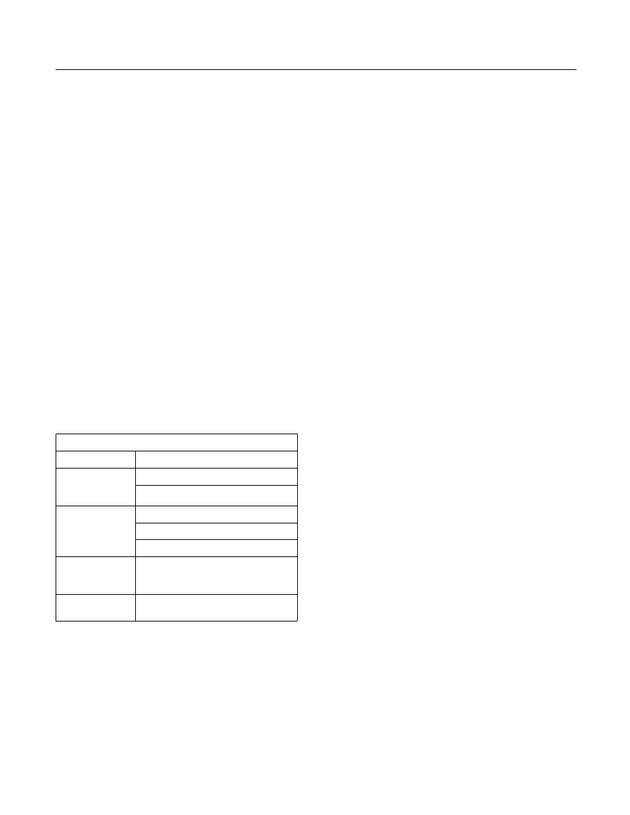
SEBU7689-10
129
Maintenance Section
Sea Water Strainer - Clean/Inspect
Inspect – Inspect the components according to
the instructions that are in Caterpillar reusability
publications. Refer to Guidelines for Reusable
Parts and Salvage Operations, SEBF8029, “Index
of Publications on Reusability or Salvage of Used
Parts”. The guidelines were developed in order to
help Caterpillar dealers and customers to avoid
unnecessary expenditures. New parts are not
required if the existing parts can still be used,
reconditioned, or repaired. If the components are
not in the reusability guidelines, refer to the Service
Manual, “Specifications” module.
Rebuild – The component is reconditioned in order
to comply with reusability guidelines.
Replace – The service life of the part is exhausted.
The part may fail before the next maintenance
interval. The part must be replaced with a part that
meets functional specifications. The replacement
part may be a new part, a CAT remanufactured part,
a rebuilt part, or a used part. Some worn components
may be exchanged with your Caterpillar dealer for a
credit on replacement parts. Consult your Caterpillar
dealer about repair options for your engine.
If you elect to perform an overhaul without the
services of a Caterpillar dealer, be aware of the
recommendations in Table 17.
Table 17
Recommendations for Top End Overhauls
(1)
Service
Top End Overhaul
Cylinder head assemblies
Inspect
Rebuild
Replace
Valves
Rocker arms
Valve bridges
Inspect
Replace
Fuel Injectors
Clean/Test
Oil cooler core
(2)
Aftercooler core (Fresh water or
treated water system)
(3)
Replace
Cylinder head gaskets
Aftercooler core (salt water system)
(1)
For instructions on removal and installation of components,
see the Service Manual, “Disassembly and Assembly” module.
(2)
Refer to this Operation and Maintenance Manual, “Oil Cooler
Core - Check/Clean/Test” for the procedure.
(3)
Refer to this Operation and Maintenance Manual, “Aftercooler
Core - Clean/Test” for the procedure.
i00905687
Sea Water Strainer -
Clean/Inspect
SMCS Code: 1371-040; 1371-070
The sea water strainer must be clean in order to
allow proper engine cooling. Check the sea water
strainer for plugging. Inspect the sea water strainer
more frequently if the vessel is being operated
in water which is shallow or dirty. Refer to the
OEM recommendations for more information about
inspecting and cleaning the sea water strainer.
Ensure that the auxiliary water pump is primed and
that the suction line is open.
1. Remove the sea water strainer and clean the
screen. Remove any dirt and debris.
2. Install the sea water strainer. Fill the sea water
strainer and the suction line for the auxiliary water
pump with water.
i01113939
Starting Motor - Inspect
SMCS Code: 1451-040; 1453-040
If the starting motor fails, the engine may not start in
an emergency situation. A scheduled inspection of
the starting motor is recommended.
The starting motor pinion and the flywheel ring gear
must be in good condition in order for the engine
to start properly. The engine will not start if the
starting motor pinion does not engage the flywheel
ring gear. The teeth of the starting motor pinion and
the flywheel ring gear can be damaged because of
irregular engagement.
Inspect the starting motor for proper operation. Listen
for grinding when the engine is started. Inspect the
teeth of the starting motor pinion and the flywheel
ring gear. Look for patterns of wear on the teeth. Look
for teeth that are broken or chipped. If damaged teeth
are found, the starting motor pinion and the flywheel
ring gear must be replaced.
Electric Starting Motor
Note: Problems with the electric starting motor can
be caused by the following conditions: malfunction of
the solenoid and malfunction of the electric starting
system.
Inspect the electrical system for the following
conditions:
130
SEBU7689-10
Maintenance Section
Turbocharger - Inspect
•
Loose connections
•
Corrosion
•
Wires that are worn or frayed
•
Cleanliness
Make repairs, if necessary.
Air Starting Motor
Personal injury or death can result from improp-
erly checking for a leak.
Always use a board or cardboard when checking
for a leak. Escaping air or fluid under pressure,
even a pin-hole size leak, can penetrate body tis-
sue causing serious injury, and possible death.
If fluid is injected into your skin, it must be treated
immediately by a doctor familiar with this type of
injury.
Inspect all of the components in the air circuit for
the starting motor. Inspect all of the air lines and
connections for leaks.
If the teeth of the starting motor pinion and/or the
flywheel ring gear are damaged, the air circuit for
the starting motor must be examined in order to
determine the cause of the problem.
Removal and Installation of the
Starting Motor
Refer to the Service Manual, “Disassembly and
Assembly” module for information on removing the
starting motor and installing the starting motor.
Consult your Caterpillar dealer for assistance.
i01539769
Turbocharger - Inspect
SMCS Code: 1052-040; 1052
Periodic inspection and cleaning is recommended
for the turbocharger compressor housing (inlet side).
Any fumes from the crankcase are filtered through
the air inlet system. Therefore, by-products from oil
and from combustion can collect in the turbocharger
compressor housing. Over time, this buildup can
contribute to loss of engine power, increased black
smoke and overall loss of engine efficiency.
If the turbocharger fails during engine operation,
damage to the turbocharger compressor wheel
and/or to the engine may occur. Damage to the
turbocharger compressor wheel can cause additional
damage to the pistons, the valves, and the cylinder
head.
NOTICE
Turbocharger bearing failures can cause large quan-
tities of oil to enter the air inlet and exhaust systems.
Loss of engine lubricant can result in serious engine
damage.
Minor leakage of a turbocharger housing under ex-
tended low idle operation should not cause problems
as long as a turbocharger bearing failure has not oc-
curred.
When a turbocharger bearing failure is accompanied
by a significant engine performance loss (exhaust
smoke or engine rpm up at no load), do not continue
engine operation until the turbocharger is repaired or
replaced.
An inspection of the turbocharger can minimize
unscheduled downtime. An inspection of the
turbocharger can also reduce the chance for potential
damage to other engine parts.
Note: Turbocharger components require precision
clearances. The turbocharger cartridge must
be balanced due to high rpm. Severe Service
Applications can accelerate component wear.
Severe Service Applications require more frequent
inspections of the cartridge.
Removal and Installation
For options regarding the removal, installation, repair
and replacement, consult your Caterpillar dealer.
Refer to the Service Manual for this engine for the
procedure and specifications.
Cleaning and Inspecting
1. Remove the exhaust outlet piping and remove
the air inlet piping from the turbocharger. Visually
inspect the piping for the presence of oil. Clean
the interior of the pipes in order to prevent dirt
from entering during reassembly.

SEBU7689-10
131
Maintenance Section
Walk-Around Inspection
2. Turn the compressor wheel and the turbine wheel
by hand. The assembly should turn freely. Inspect
the compressor wheel and the turbine wheel for
contact with the turbocharger housing. There
should not be any visible signs of contact between
the turbine wheel or compressor wheel and the
turbocharger housing. If there is any indication of
contact between the rotating turbine wheel or the
compressor wheel and the turbocharger housing,
the turbocharger must be reconditioned.
3. Check the compressor wheel for cleanliness.
If only the blade side of the wheel is dirty, dirt
and/or moisture is passing through the air filtering
system. If oil is found only on the back side of the
wheel, there is a possibility of a failed turbocharger
oil seal.
The presence of oil may be the result of extended
engine operation at low idle. The presence of oil
may also be the result of a restriction of the line for
the inlet air (plugged air filters), which causes the
turbocharger to slobber.
4. Use a dial indicator to check the end clearance
on the shaft. If the measured end play is greater
than the Service Manual specifications, the
turbocharger should be repaired or replaced.
An end play measurement that is less than the
minimum Service Manual specifications could
indicate carbon buildup on the turbine wheel. The
turbocharger should be disassembled for cleaning
and for inspection if the measured end play is less
than the minimum Service Manual specifications.
5. Inspect the bore of the turbine housing for
corrosion.
6. Clean the turbocharger housing with standard
shop solvents and a soft bristle brush.
7. Fasten the air inlet piping and the exhaust outlet
piping to the turbocharger housing.
i02706582
Walk-Around Inspection
SMCS Code: 1000-040
Inspect the Engine for Leaks and
for Loose Connections
A walk-around inspection should only require a few
minutes. When the time is taken to perform these
checks, costly repairs and accidents can be avoided.
For maximum engine service life, make a thorough
inspection of the engine compartment before starting
the engine. Look for items such as oil leaks or coolant
leaks, loose bolts, worn belts, loose connections and
trash buildup. Make repairs, as needed:
•
The guards must be in the proper place. Repair
damaged guards or replace missing guards.
•
Wipe all caps and plugs before the engine is
serviced in order to reduce the chance of system
contamination.
NOTICE
For any type of leak (coolant, lube, or fuel) clean up the
fluid. If leaking is observed, find the source and correct
the leak. If leaking is suspected, check the fluid levels
more often than recommended until the leak is found
or fixed, or until the suspicion of a leak is proved to be
unwarranted.
NOTICE
Accumulated grease and/or oil on an engine or deck is
a fire hazard. Remove this debris with steam cleaning
or high pressure water.
•
Ensure that the cooling lines are tight and ensure
that the cooling lines are properly clamped. Check
for leaks. Check the condition of all pipes.
•
Inspect the water pumps for coolant leaks.
Note: The water pump seal is lubricated by coolant
in the cooling system. It is normal for a small amount
of leakage to occur as the engine cools down and
the parts contract.
Excessive coolant leakage may indicate the need
to replace the water pump seal. For the removal of
water pumps and the installation of water pumps
and/or seals, refer to the Service Manual for the
engine or consult your Caterpillar dealer.
•
Inspect the lubrication system for leaks at the front
crankshaft seal, the rear crankshaft seal, the oil
pan, the oil filters and the valve cover.
•
Inspect the fuel system for leaks. Look for loose
fuel line clamps.
•
Inspect the piping for the air inlet system and the
elbows for cracks and for loose clamps.
•
Inspect the alternator belt and the accessory drive
belts for cracks, breaks or other damage.
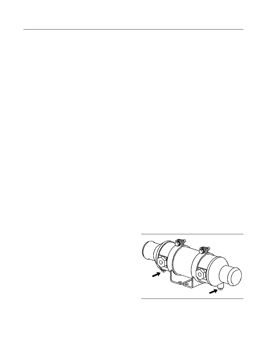
132
SEBU7689-10
Maintenance Section
Water Pump - Inspect
Belts for multiple groove pulleys must be replaced as
matched sets. If only one belt is replaced, the belt will
carry more load than the belts that are not replaced.
The older belts are stretched. The additional load on
the new belt could cause the belt to break.
•
Drain the water and the sediment from fuel tanks
on a daily basis in order to ensure that only clean
fuel enters the fuel system.
•
Inspect the wiring and the wiring harnesses for
loose connections and for worn wires or frayed
wires.
•
Inspect the ground strap for a good connection and
for good condition.
•
Inspect the ECM to the cylinder head ground strap
for a good connection and for good condition.
•
Disconnect any battery chargers that are not
protected against the current drain of the starting
motor. Check the condition and the electrolyte level
of the batteries, unless the engine is equipped with
a maintenance free battery.
•
Check the condition of the gauges. Replace any
gauges which are cracked and replace any gauges
that can not be calibrated.
i03543200
Water Pump - Inspect
SMCS Code: 1361-040; 1361
A failed water pump might cause severe engine
overheating problems that could result in the following
conditions:
•
Cracks in the cylinder head
•
A piston seizure
•
Other potential damage to the engine
A failed water pump might cause severe engine
overheating problems that could result in cracks in
the cylinder head, a piston seizure or other potential
damage to the engine.
Visually inspect the water pump for leaks. If leaking
of the water pump seals is observed, replace all of
the water pump seals. Refer to two articles in the
Disassembly and Assembly Manual, “Water Pump
- Disassemble and Water Pump - Assemble” for
the disassembly and assembly procedure. If it is
necessary to remove the water pump, refer to two
articles in the Disassembly and Assembly Manual,
“Water Pump - Remove and Water Pump - Install”.
Inspect the water pump for wear, cracks, pin holes
and proper operation. Refer to the Parts Manual
for the correct part numbers for your engine or
consult your Caterpillar dealer if repair is needed or
replacement is needed.
i03612482
Zinc Rods - Inspect/Replace
SMCS Code: 1388-040; 1388-510
Corrosion in sea water circuits can result in premature
deterioration of system components, leaks, and
possible cooling system contamination.
Zinc rods are inserted in the sea water cooling
system of the engine in order to help prevent the
corrosive action of salt water. The reaction of the zinc
to the sea water causes the zinc rods to deteriorate.
The zinc rods deteriorate instead of engine parts
for the cooling system that are more critical. Rapid
deterioration of zinc rods may indicate the presence
of uncontrolled electrical currents from improperly
installed electrical attachments or improperly
grounded electrical attachments.
The zinc rods must be inspected at the proper
intervals. The zinc rods must be replaced when
deterioration occurs.
Inspect the zinc rods within 24 hours of initially
filling the plumbing with sea water. If no significant
corrosion is noted, inspect the zinc rods weekly or
inspect the zinc rods after each 50 hours of engine
operation. If no significant deterioration is noted,
inspect the zinc rods weekly or inspect the zinc rods
after each 50 hours of engine operation.
Locations of the Zinc Rods
g01937139
Illustration 87
One or two zinc rods may be located in the oil cooler.
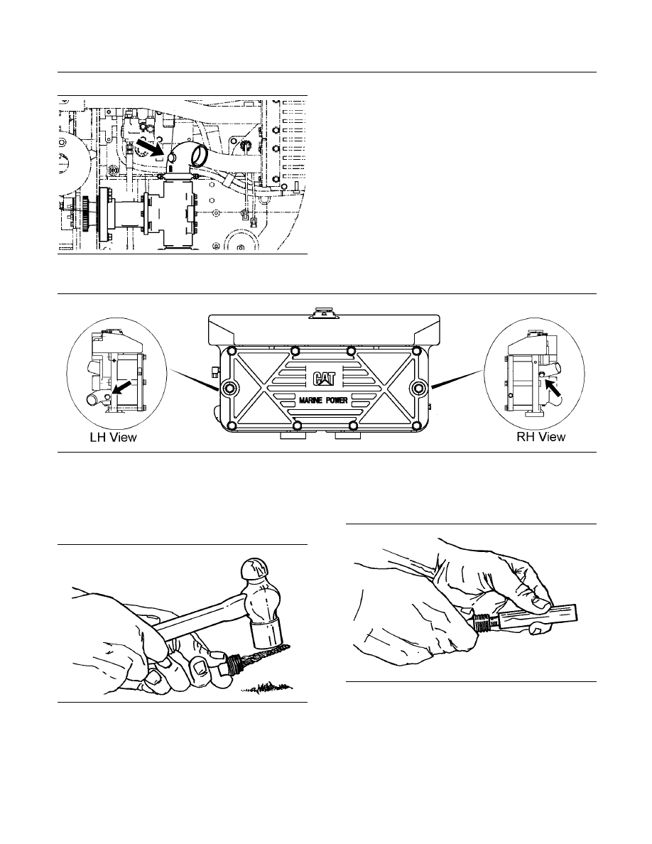
SEBU7689-10
133
Maintenance Section
Zinc Rods - Inspect/Replace
g01937142
Illustration 88
One zinc rod is located on top of the auxiliary water pump.
g01937141
Illustration 89
One zinc rod is located in the intake for the heat exchanger. One zinc rod is located in the outlet for the heat exchanger.
Inspect the Zinc Rods
1. Remove the zinc rod.
g00104048
Illustration 90
2. Tap the zinc rod lightly with a hammer. If the zinc
rod has deteriorated, or if the zinc rod flakes,
install a new zinc rod.
Replace the Zinc Rods
g00104049
Illustration 91
1. Unscrew the old zinc rod or drill the old zinc rod
from the plug. Clean the plug.
2. Apply
9S-3263 Compound to the shoulder of
a new zinc rod. Apply the compound only to the
shoulder of the zinc rod. Install the zinc rod into
the plug.

134
SEBU7689-10
Maintenance Section
Zinc Rods - Inspect/Replace
3. Coat the external threads of the plug with
5P-3413 Pipe Sealant. Install the zinc rod. Refer
to the Specifications Manual for more information
on torque specifications.
Wyszukiwarka
Podobne podstrony:
Plans For Steam Marine Engine
Vertical Steam Marine Engine
Bicycle Maintenance
4 Steyr Operation and Maintenance Manual 8th edition Feb 08
Diesel engine, Akademia Morska -materiały mechaniczne, szkoła, Mega Szkoła, Szkoła moje
4607, Akademia Morska, Atlantic United Marine
04 Engine
Mazda 6 (Mazda6) Engine Workshop Manual Mzr Cd (Rf Turbo)(3)
Post feeding larval behaviour in the blowfle Calliphora vicinaEffects on post mortem interval estima
International politics judicial intervention
INTERVIEWS WITHDAVID GEMMELL no 2
INTERVIEWS WITHDAVID GEMMELL no 3
M31f1 Engine Controls 1 54
Engine Compartment 4 7
10 Engine Control System
interview tips
Computer engine control
ARTICLE MAINT INSPECTION ENGINE
engineering projects
więcej podobnych podstron