
v
Quality of Service for Voice over IP Solutions Guide
Version 1.0
Preface
This preface introduces the QoS for Voice Over IP Solutions Guide, which explains quality of service
for Voice over IP (QoS for VoIP) and addresses how to deploy end-to-end QoS for voice traffic
throughout the components of an internetwork. It also identifies who should use this guide and how it
is intended to be used. Read this preface to determine if this guide is appropriate for your internetwork
requirements.
About the QoS for Voice over IP Solutions Guide
Because they are real-time based, voice applications tolerate minimal packet delay and loss. Cisco IOS
QoS features collectively embody techniques that offer the means to provide priority service that meets
the stringent requirements of voice applications. In describing why and how you should deploy QoS for
VoIP throughout your network, the guide does the following:
•
Gives an overview of QoS for VoIP and describes applicable QoS features.
•
Explains the optimum approaches to take in applying QoS for voice applications in the campus
(enterprise) network using Frame Relay or PPP across 64 K or T1 lines.
A later version of this guide will include an overview of the internetwork topology used throughout this
book to illustrate end-to-end QoS for VoIP. The later version will also include scenarios describing
corporate use of an Internet service provider (ISP) for long-distance voice communication using ATM
or using Packet over Sonet (POS).
Who Should Use This Guide?
You should use this guide if your network is configured to support VoIP applications concurrent with
data applications or if you intend to configure your network as such, and you fit the following described
audience profile. The audience for this publication should understand basic networking principles and
terminology, and should have hands-on experience in administering a network.
The assumed target audience for this guide is broadly characterized as follows:
•
System administrators responsible for installing and configuring networking equipment that are
familiar with the fundamentals of router-based internetworking, and are familiar with Cisco IOS
software and Cisco products.
•
System administrators that have substantial background in configuring networks, but that might not
have experience with Cisco products and Cisco-supported protocols.
•
Customers with technical networking background and experience.

vi
Quality of Service for Voice over IP Solutions Guide
Version 1.0
Preface
How to Use This Guide
This guide does not require that users be familiar with QoS concepts or protocols or how they apply to
VoIP. This guide gives an overview of the QoS features and protocols specific to VoIP. For those users
new to Cisco products and Cisco-supported protocols, refer to the Quality of Service Solutions
Configuration Guide, which belongs to the Cisco IOS Reference Library
(http://www.cisco.com/univercd/cc/td/doc/product/software/ios120/12cgcr/qos_c/index.htm) for
additional QoS concepts.
How to Use This Guide
The first two chapters of this guide provide conceptual information; the last chapter gives examples of
how to apply this information to configure end-to-end QoS for VoIP paths throughout a campus
(enterprise) network. Reading the entire guide will enable you to identify which QoS protocols are
appropriate for your network. Use this guide in the following way:
•
To gain understanding of the issues entailed in configuring a network for concurrent voice
application and data application support using VoIP for voice traffic, read Chapter 1.
•
For detailed information about the QoS features applicable to voice applications using VoIP, read
Chapter 2.
•
For illustration of how to apply these QoS features to paths throughout an enterprise network across
various link types and speeds, read Chapter 3.

C H A P T E R
1-1
Quality of Service for Voice over IP Solutions Guide
Version 1.0
1
QoS for Voice over IP Solutions Overview
This chapter briefly discusses how the rapid and widespread movement toward integrated transport of
voice and data across IP has brought forth specific requirements and challenges best addressed by
strategic deployment of quality of service (QoS) technologies. Many of these challenges exist because
the requirements of real-time voice applications are so different from those of traditional data
applications.
This chapter explains the fundamental requirements intrinsic to end-to-end internetwork transportation
of packetized voice traffic and why deployment of QoS features is necessary to meet voice traffic
requirements and adequately surmount the challenges inherent in integrating voice and data transport.
This chapter includes these sections:
•
About Integration of Voice and Data in Internetworks
•
About QoS for VoIP
•
About the Basic Requirements for Voice Traffic
About Integration of Voice and Data in Internetworks
Corporations are integrating transport of voice and data communication across the same infrastructure for
fiscal as well as technological advantage. Some companies are designing entirely new voice-and-data
integrated internetworks. Other companies are overhauling their traditional data networks, redesigning
them to include infrastructure to support packetized voice transmission.
Companies that carry data traffic that exceeds voice traffic in volume design their networks principally
for data transport. These companies build into the design, as a secondary requirement, the ability to also
carry voice traffic. Other companies give preference to voice traffic. Thus, companies take various
approaches to integration of voice and data traffic in their networks.
Geographically dispersed enterprises with large WAN networks are migrating to Frame Relay (FR)
routed networks and ATM switched networks because these networks support both voice and data
traffic. Enterprises that depend on Systems Network Architecture (SNA) and other transaction-oriented
protocols are migrating to IP networks to establish infrastructure for voice transmission.
The Cisco Voice over IP (VoIP) technology transcends the differences among these transport media and
mechanisms because the lower-layer media used is transparent to an IP infrastructure. For VoIP, the
underlying technology might be ATM, FR, point-to-point lines, POS, or a WAN link. In fact, many
internetworks include all of these media types. Cisco IOS operates with all of these link layer
technologies, creating interoperability at the both the IP and link layers, integrating them to produce
end-to-end solutions.

1-2
Quality of Service for Voice over IP Solutions Guide
Version 1.0
Chapter 1
QoS for Voice over IP Solutions Overview
About VoIP
The Quality of Service for VoIP Solutions Guide focuses exclusively on use of the Cisco VoIP to provide
end-to-end QoS support for voice traffic. You should read this guide if your network carries voice traffic
today or if you plan to implement support for voice traffic.
About VoIP
This section describes VoIP, and it suggests why you should use VoIP for voice transmission. It includes
these subsections:
•
What Is VoIP?
•
Why Use VoIP for Packetized Voice?
What Is VoIP?
VoIP enables Cisco routers and switches to carry telephony-style voice traffic—that is, live, packetized
voice traffic such as telephone calls—over IP-based data networks (intranetworks or internetworks)
rather than Public Switched Telephone Networks (PSTN). Cisco routers and switches are equipped to
handle origination, transport, and termination of VoIP traffic. VoIP enables toll bypass, remote PBX
presence over WANs, unified voice and data trunking, and POTS-Internet telephony gateways.
VoIP is IP-based. IP is considered a connectionless or best-effort transport when used in conjunction
with the User Datagram Protocol (UDP). UDP, which is datagram-based (or connectionless), suits the
specific requirements of voice traffic, so it is used as the transport for VoIP rather than TCP. UDP is
preferable for voice despite the fact that TCP, which is connection-oriented, is considered a more ideal
transport mechanism because of its built-in reliability.
Consider the underlying reasons for using UDP as the transport for voice traffic:
•
Retransmission of dropped packets—the behavior in TCP—is far worse for delay-sensitive voice
traffic than is packet loss.
•
Because UDP is stateless, it removes from the CPU the burden of overhead entailed in maintaining
state on connection-oriented protocols such as TCP.
•
From an application perspective, VoIP uses small-sized packets that are sent out at consistent
intervals depending on the digital signal processor (DSP) and codec (coder-decoder) used. The
UDP header, which is 8 bytes long, is smaller in size than the TCP 20-byte header and thus costs
less in bandwidth and overhead.
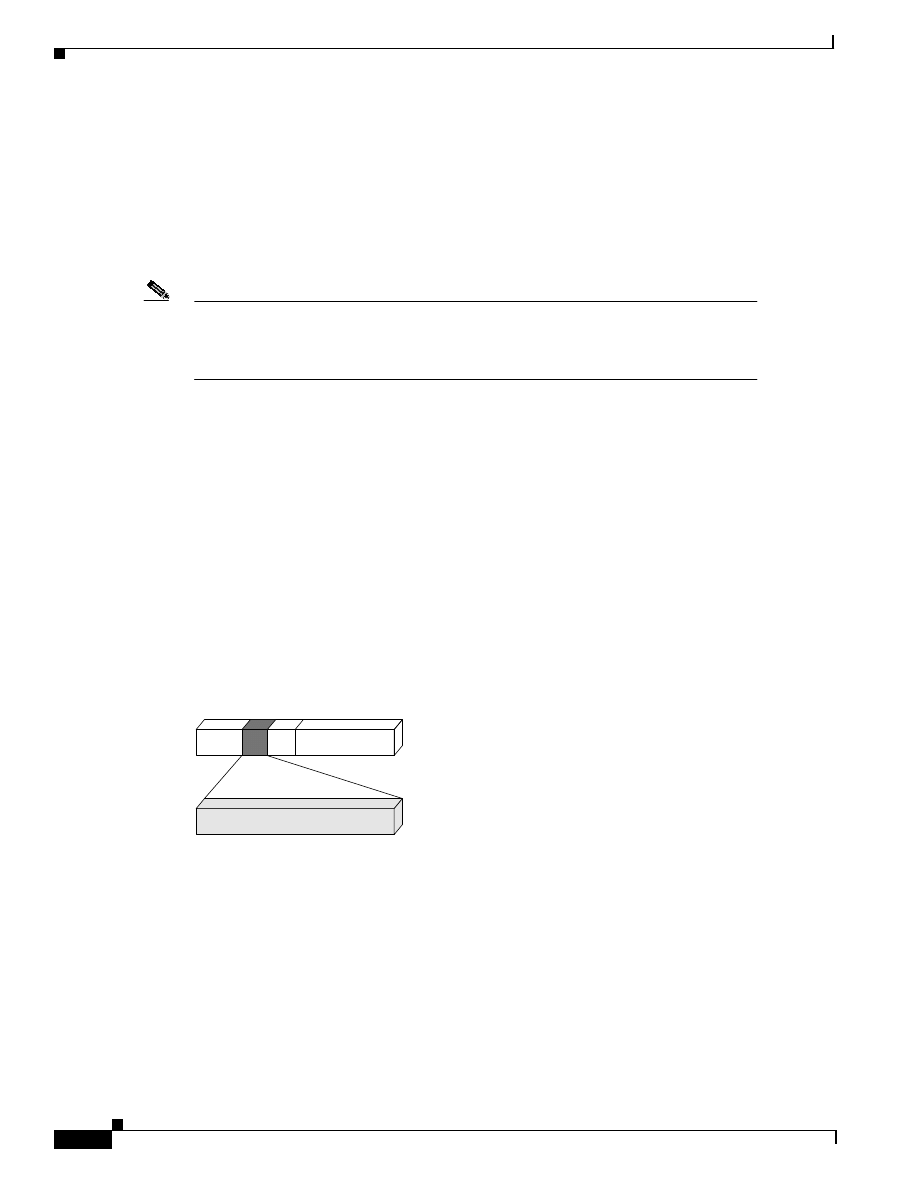
Figure 1-1 shows the VoIP packet.
Figure 1-1
VoIP Packet Structure
VoIP packet
Voice
payload
RTP
header
UDP
header
IP
header
Link
header
X Bytes
12 Bytes
8 Bytes
20 Bytes
X Bytes
27091

1-3
Quality of Service for Voice over IP Solutions Guide
Version 1.0
Chapter 1
QoS for Voice over IP Solutions Overview
About QoS for VoIP
TCP offers reliability in that it guarantees retransmission of lost frames, but this reliable delivery is
useless in the internetwork transportation of packetized voice because a frame that arrives late as a
result of retransmission is as useful as no frame at all—that is, it has no effect. In other words,
retransmission of packets is not meaningful. By the time the resent packet arrives at the end user
endpoint, the required delivery time has long been transgressed.
Why Use VoIP for Packetized Voice?
The many reasons to use VoIP for voice traffic include the following:
•
Because IP is ubiquitous, it provides contiguous connectivity independent of the media transport
that carries it.
Use of VoIP transcends the differences among various transport media and mechanisms because the
media used is transparent to an IP infrastructure. The contiguous connectivity of IP offers an
important benefit to real-time applications that is not available through direct use of other Cisco
technologies, such as Voice over ATM (VoATM) or Voice over Frame Relay (VoFR).
•
VoIP traffic is easily integrated with traffic from modern applications such as unified messaging or
virtual call centers.
•
As a technology for transporting voice calls, VoIP packet-switched traffic offers cost benefit over
circuit-switched networks. One reason for this cost benefit is that Cisco IOS IP-based networks are
less expensive to build and maintain than are circuit-switched networks.
About QoS for VoIP
This section briefly explains QoS and its purposes. Then, it explains why QoS is necessary for voice
traffic.
Cisco IOS QoS features collectively embody techniques that you can employ to meet the stringent
requirements of voice traffic delivery, including curtailment of packet loss and constancy of delay. They
offer the means to provide priority service through service differentiation, a derived or secondary
benefit of which is the ability to offer customers different classes of service with different cost
structures.
This section includes these subsections:
•
What Is QoS?
•
Why Is QoS for VoIP Necessary?
What Is QoS?
QoS refers to the ability of a network to provide better service to selected network traffic over various
underlying technologies. QoS is not inherent in a network infrastructure. Rather, you must institute QoS
by strategically deploying features that implement it throughout the network.
Effective end-to-end QoS throughout an internetwork must serve disparate users, applications,
organizations, and technologies, all at a reasonable cost and effort. QoS technologies for VoIP enable
you to balance service levels for user satisfaction—granting priority service to voice, for instance, while
servicing data transmission to the degree of fairness that you require—with efficient backbone and
access utilization to minimize operations expenses.

1-4
Quality of Service for Voice over IP Solutions Guide
Version 1.0
Chapter 1
QoS for Voice over IP Solutions Overview
About QoS for VoIP
QoS features for voice that implement reliability and predictability eliminate poor quality voice
transmission, including crackles and missing syllables that render the call unsatisfactory (even
incoherent) to the recipient. For a voice application, minimal QoS support consists of mechanisms that
provide these assurances:
•
Reliability, which ensures voice packet delivery without packet loss.
•
Predictability, which promises voice packet delivery without an excessive amount of delay. (Delay
is often expressed in distorted reconstruction of the transmitted conversation.)
QoS features offer other advantages for transmission of voice traffic. For instance, use of QoS for voice
gives Internet Service Providers (ISPs) the means to offer their customers differentiated services with
different associated costs. ISPs can offer a spectrum of new applications and additional paid-for
services based on these levels of service. Without differentiated services, most ISPs offer a standard $20
a month service to residential subscribers. Use of a standard fee significantly reduces profit margins
afforded the ISP, limiting any revenue gains the ISP might accrue to revenues from a small number of
business clients.
Why Is QoS for VoIP Necessary?
With increasingly pervasive and heavy use of the Internet and intranets, deployment of QoS for voice
becomes a fundamental necessity. In traditional voice and data terminal networks, data flow and
throughput were predictable. Network usage today makes it hard to predict data flow and to time bursts
of data.
Moreover, networking equipment and end stations that carry both data and voice cannot differentiate
traffic that requires high-priority connections from traffic that does not require priority service. Without
QoS, it is impossible to ensure that voice traffic (considered critical traffic) is expedited or that it will
receive constant, predictable transmission performance across a backbone shared by data traffic.
The requirements and behaviors intrinsic to the transmission of voice versus data across an internetwork
differ in a number of ways. Here is how they compare:
•
Data is bursty by nature, while voice is deterministic (smooth).
•
TCP-based data applications react to dropped packets, while UDP-based voice applications can
only conceal dropped packets.
Data applications respond to dropped packets with some degree of correction because often they
are TCP-based (TCP resends dropped packets). Voice (which relies on the best-effort transmission
of UDP) cannot truly respond to and recover from packet loss, although in some cases the complex
algorithms underlying voice transmission can conceal packet loss.
•
Data is delay-insensitive, while voice is delay-sensitive.
Delay-insensitivity means that data applications can tolerate delay well because they are not
real-time-based. Voice responds negatively to delay, creating so-called “holes” in the transmission
as heard by the receiver.
These differences alone mandate use of QoS strategies for internetworks that carry both voice and data.
Effective transport of voice traffic over IP must entail reliable delivery of packets with low latency.
Because VoIP appropriately uses UDP/RTP as its transport and UDP is not reliable, other mechanisms
must be put in place to ensure reliable delivery of voice packets. QoS features offer strict priority
service to voice traffic to ensure reliable delivery.
Transmission of voice packets, usually small in size, ranging from 80 to 256 bytes, can be unduly
delayed between large data packets unless QoS techniques such as packet fragmentation and
interleaving are used.

1-5
Quality of Service for Voice over IP Solutions Guide
Version 1.0
Chapter 1
QoS for Voice over IP Solutions Overview
About the Basic Requirements for Voice Traffic
About the Basic Requirements for Voice Traffic
This section identifies packet delay and packet loss as the two most stringent requirements that
characterize voice traffic transmission. To gain sufficient understanding of why these requirements must
be met for acceptable transmission of voice traffic, see “Basic Requirements for Voice Traffic.”
It is not necessary to read the details on delay and loss in order to understand the QoS features for voice,
which are described in Chapter 2. However, understanding loss and delay in detail helps explain why
and how certain QoS features are used under certain circumstances for integration of voice and data
traffic.
This section includes these subsections:
•
Basic Requirements for Voice Traffic
•
About Delay
•
About Loss
Basic Requirements for Voice Traffic
Voice traffic is intolerant of packet loss and delay primarily because these conditions degrade the
quality of voice transmission delivered to the recipient end user. Delay must be constant for voice
applications. The complete end-to-end absolute delay budget for voice traffic is 200 milliseconds (ms).
Here are some voice application requirements that address loss and delay:
•
The network must provide strict policing of traffic.
•
Bandwidth for voice traffic must meet minimal requirements.
•
Voice traffic requires priority service over large data packets using the same link.
About Delay
Here are some causes of voice packet delay at the campus edge and egress switches and routers:
•
Congestion
•
Lack of traffic shaping
•
Large packet serialization on slow links
•
Variable size packets
Here are some causes of delay in the WAN:
•
Global WAN congestion
•
Central-to-remote site speed mismatches (that is, transmission of voice and data from a fast link to
a slow one without adequate traffic shaping)
•
Oversubscription of PVCs
•
Bursting above committed rates
Two characteristic types of delay affect voice traffic: absolute delay and delay variation. Absolute delay
is essentially the time it takes for voice packets, or speech, to travel from the source to the destination.
Delay variation (jitter) is delay in which the absolute delay from the source to the destination varies

1-6
Quality of Service for Voice over IP Solutions Guide
Version 1.0
Chapter 1
QoS for Voice over IP Solutions Overview
About the Basic Requirements for Voice Traffic
from packet to packet. Variation in delay occurs because of variation of interpacket arrival time. Even
though absolute delay might be minimal, a variation in this delay on a packet-by-packet basis can
degrade voice quality.
Absolute delay can interfere with the standard rhythm or cadence of a phone call. Variation in delay can
impact speech quality. If the wait between when signal elements are sent and when they arrive varies,
voice traffic no longer will be synchronized or it may fail. (In other words, a slight time or phase
movement in a transmission signal can introduce loss of synchronization.)
Two sources of delay are handling delay and propagation delay. If the amounts of these kinds of delay
vary, they contribute to delay variation. Handling delay is incurred as the result of a process such as
encoding (codec). Analog voice undergoes encoding during its conversion to digital information before
it is packetized. As mentioned previously, handling delay can also occur when a voice packet is moved
to the outbound queue for transmission. (This type of handling delay, which is called serialization delay,
can occur on a hop-by-hop basis.) Propagation delay can also occur when a voip packet is moved to an
I/O queue for transmission.
Another factor contributing to delay is latency. Latency refers to the time between when a device
requests access to a network and when it is granted permission to send. End-to-end latency describes
the overall delay associated with a network. Serialization delay is an aspect of latency that addresses
the time it takes to send a packet out an interface—that is, the time it takes to move the actual packet to
the output queue. The time it takes to put voice traffic onto a transmission line depends on the data
volume and the speed of the line—for instance, it takes about 5 ms to send a 1024-byte packet on a
1.544–Mbps T1 line.
Note
You should hold output queue delay to under 10 ms if possible through use of the most
optimal QoS queueing feature for the node and network.
The effect of serialization delay can be such that a single link can cause enough delay to exceed the
entire end-to-end 200–ms delay budget for voice traffic.
Here are two causes of serialization delay:
•
The encoding process and the codec used. For instance, the G.729 codec, which is a type of
compression that enables voice to be coded into 8-kbps streams, has an algorithmic delay of about
20 ms. (Different codec compression methods introduce different amounts of delay.)
•
Packetization. VoIP supports a variable payload size, allowing you to specify how many bytes of
payload should be included in each voice packet. In the Cisco IOS VoIP product, the DSP generates
a frame every 10 ms. You can decide how many frames you want to send in one packet. Larger
payloads reduce the packet-per-second load of each voice channel, which is traded off against delay
of the voice connection.
Packet-switching is another underlying source of delay. Packet-switching delay refers to the latency
accrued when bridges, switches, and routers forward data. The latency depends on the speed of the
internal circuitry and CPU, and the switching architecture of the internetworking device.

1-7
Quality of Service for Voice over IP Solutions Guide
Version 1.0
Chapter 1
QoS for Voice over IP Solutions Overview
About the Basic Requirements for Voice Traffic
About Loss
Networks can drop voice packets for a number of reasons under different circumstances, even under
circumstances meant to provide benefits. Here are some examples of ways packet-drop problems can
be introduced by strategies otherwise beneficial to data traffic:
•
On Frame Relay networks, the committed information rate (CIR) specifies the guaranteed amount
of information carried during periods of congestion. During bursting over the CIR—a beneficial,
common, and intentional practice in a data-only Frame Relay network—voice packets are sent out
into the Frame Relay network essentially in a best-effort manner, subjecting them to packet drop.
(Configuring traffic shaping—which is applicable to Frame Relay and ATM networks only, not
leased lines—ensures that the CIR is not exceeded, thus avoiding occurrence of packet drop under
these circumstances.)
•
Oversubscription, another commonly used Frame Relay design implementation on data-only
environments, makes it possible for many remote sites to feed into a central site. Depending on
network conditions, oversubscription puts at risk the quality of voice traffic transmission. Under
conditions of oversubscription, the aggregate line speeds and CIR of the remote sites can easily
exceed the line speed (link bandwidth) of the central site circuit. Problems affecting voice traffic
can also occur if the CIRs of the remote sites all equal less than the central site link speed but the
bursting at the remote sites exceeds the central site link speed. If you run voice traffic over a
network designed along these lines and the amount of traffic from the remote sites exceeds the
circuit speed buffering at the central site, delay will result. Moreover, if the remote-to-central burst
period is large enough, packet drop might also occur. (To eliminate congestion resulting from the
oversubscription of the remote sites to the central site in order to avoid delay and packet drop, use
traffic shaping from the remote sites.)
To avoid packet loss that can severely degrade voice quality, you should deploy mechanisms that inhibit
its occurrence, such as strict priority service.
To configure guaranteed strict priority for voice traffic, you can use the IP RTP Priority feature on Cisco
2600, 3600, and 7200 series systems running release 12.0(7)T or later. This feature allows you to
specify the exact amount of bandwidth allocated for the priority queue used to handle voice flows. IP
RTP Priority closely polices use of bandwidth and if the configured amount is exceeded, IP RTP Priority
drops voice packets. (Allocating more than the exact requisite bandwidth for the voice flow—taking
into account the type of codec compression used and the interface characteristics—protects against
occurrence of packet drop under these circumstances.)
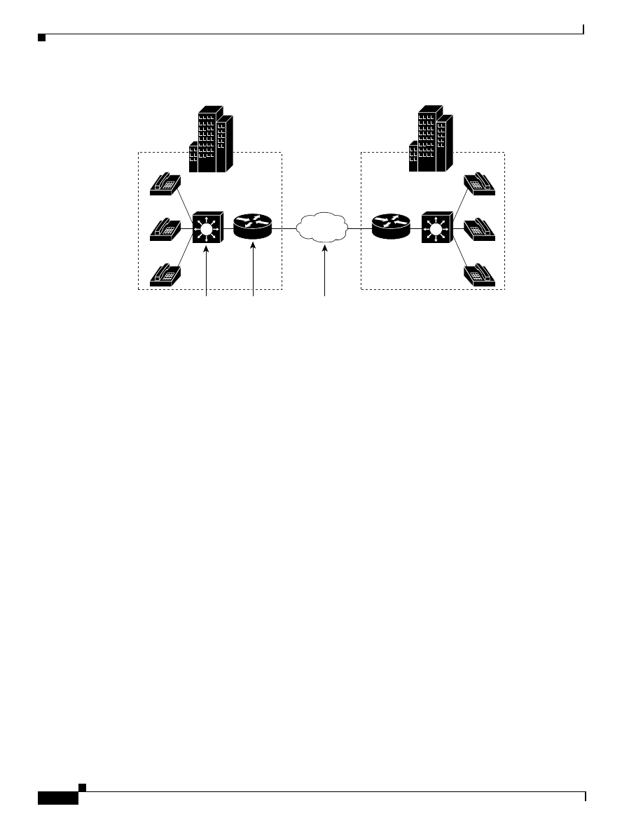
Packet loss is most likely to occur in the part of the network referred to as the router egress into the
WAN, although it can occur anywhere in the network. Figure 1-2 shows a basic representation of an
internetwork composed of two campus networks communicating across a WAN. Notice that the router
at the edge of the campus on the left is the egress into the WAN to its right. It is here that you would
configure QoS features to inhibit packet loss.
1-8
Quality of Service for Voice over IP Solutions Guide
Version 1.0
Chapter 1
QoS for Voice over IP Solutions Overview
About the Basic Requirements for Voice Traffic
Figure 1-2
Internetwork Domains and QoS Considerations
IP
IP
IP
IP
IP
IP
Multilayer
campus
Campus
WAN
edge/egress
WAN
backbone
Multilayer
campus
Router
WAN
Router
27090

C H A P T E R
2-1
Quality of Service for Voice over IP Solutions Guide
Version 1.0
2
QoS Features for Voice over IP
Cisco IOS QoS includes a rich set of features designed to enable you to deploy mechanisms that deliver
quality of service throughout your network. Many of these features address the requirements of
end-to-end QoS and service differentiation for voice packet delivery. The subset of QoS features for
Voice over IP (VoIP) includes technologies that enable you to do the following:
•
Classify traffic in order to differentiate it
•
Police traffic and shape it
•
Manage traffic congestion when it occurs
•
Configure the system to avoid congestion where possible
•
Fragment large data packets and interleave them with voice packets to meet the delivery
requirements of voice
•
Offer bandwidth guarantees and reservation to high-priority voice traffic
Thus, QoS for VoIP entails deploying features that ensure no loss, low and constant delay, no or minimal
jitter, and guaranteed bandwidth—requirements for voice explained in Chapter 1, “QoS for Voice over
IP Solutions Overview.”
Cisco IOS QoS for VoIP features have the following properties:
•
They are best deployed at different points in the network and are designed to be used in conjunction
with other QoS features to achieve goals such as control over jitter and delay.
•
They are designed to support packet transmission over certain link types. (Not all QoS for VoIP
features are supported on all platforms.)
Complete details for the QoS features introduced in this chapter, including configuration information,
are provided in the appropriate Cisco IOS configuration and command reference documentation.
Cisco IOS QoS software includes these major feature categories applicable to VoIP traffic:
•
Congestion Management
•
Link Efficiency Mechanisms
•
Congestion Avoidance
•
Traffic Shaping and Policing
•
Classification
•
IP to ATM CoS
•
Signalling

2-2
Quality of Service for Voice over IP Solutions Guide
Version 1.0
Chapter 2
QoS Features for Voice over IP
Congestion Management
Note
Cisco IOS software is enhanced and extended on a continuing basis to include new QoS
features, many of which are being implemented or planned for near-future
implementation. Consult with your support engineer (SE) to determine if releases of Cisco
IOS software later than 12.0(5)T support additional QoS techniques applicable to voice
exceeding those described in this guide.
Congestion Management
A network carrying voice traffic also carries data. Voice and data traffic sharing a path through the
network can interact with one another in ways that affect the application performance of each,
sometimes resulting in network congestion and packet loss. Congestion results from a sustained
overload of traffic and it can manifest in performance degradation and packet loss unacceptable in the
case of voice traffic delivery.
Congestion management features have the following properties:
•
They operate to control congestion once it occurs.
•
The embody queueing and scheduling disciplines that allow individual connections such as those
used for voice to obtain guarantees on bandwidth, delay, and jitter, thus enabling guaranteed service
that meets the performance requirements of a voice application.
•
They support cooperative transmission of voice and data across a single path between routers.
To control congestion once it occurs, you can implement strategies using queueing and scheduling
features. The use of queueing and scheduling mechanisms to meet specified bandwidth allocation or
delay bounds applies to both the output of the edge devices and the core devices of the network.
Once you deploy congestion management features by configuring them, the techniques dynamically
tailor themselves to existing network conditions as congestion arises. Deployment of congestion
management features throughout your network allows you to ensure that time-critical voice traffic
receives the priority transmission it requires.
About Queueing and Scheduling
When voice traffic is to be carried on packet networks, queueing generally functions to give voice
priority over data traffic. Queueing is a mechanism that packet-based networks use to absorb bursts of
traffic that are in excess of trunk bandwidth; packets awaiting transmission are buffered, or queued.
Queueing is only necessary if congestion can occur in the network. When there is more trunk bandwidth
available than traffic using it—say, up to 50 percent utilization—and trunk bandwidth allows several
data frames to be queued before a voice frame without undue transmission delay to the voice frame, any
configured queues would be empty or near-empty, and thus not needed.
A scheduling discipline determines which queue to service next. It decides the order in which the switch
or router serves the buffered data. It allocates different delays to different users by its choice of service
order, and it allocates different loss rates to different users by its choice of which requests to drop.
Apart from guaranteed strict priority service, most queueing and scheduling techniques enable you to
grant voice traffic standard priority service. Standard priority treatment is not strict priority and the
techniques that provide it must also address the needs of other enqueued data. For this reason, you must
use other QoS features such as fragmentation and interleaving to fragment data packets so as to reduce
their size and interleave the fragments with voice packets.

2-3
Quality of Service for Voice over IP Solutions Guide
Version 1.0
Chapter 2
QoS Features for Voice over IP
Congestion Management
Cisco IOS QoS software offers many congestion management protocols for different platforms whose
features address the requirements of voice traffic while ensuring that data transmission is not penalized.
This section describes the following congestion management features:
•
MDRR (Modified Deficit Round Robin)
•
WRR (Weighted Round Robin)
•
WFQ (Weighted Fair Queueing)
There are two kinds of standard WFQ and three kinds of Distributed Weighted Fair Queueing
(DWFQ):
–
Flow-Based WFQ
–
CBWFQ (Class-based Weighted Fair Queueing)
There are three kinds of DWFQ:
–
Flow-Based DWFQ
–
QoS Group-Based DWFQ
–
ToS-Based DWFQ
•
IP RTP Priority (Internet Protocol Real-Time Transfer Priority)
•
Priority Queueing within CBWFQ
The last two features allow you to reserve a queue for voice. IP RTP Priority grants strict priority based
on port range, and priority queueing within CBWFQ grants strict priority based on a wide range of
criteria that you can use to determine what constitutes a class.
How Do WFQ, DWFQ, and CBWFQ Apply to Voice Traffic?
Availability of strict priority for voice traffic through use of IP RTP Priority in Cisco IOS Release
12.0(5)T renders use of WFQ as a queueing and scheduling mechanism far less essential and necessary
than it was in prior releases. You can use IP RTP Priority to specify voice traffic to be enqueued in the
strict priority queue. Also, you can use the priority queueing within CBWFQ feature to configure a class
for strict priority and control the bandwidth allocated to that class. For instance in CBWFQ, you can
give high bandwidth to a class, thereby giving it very low weight.
WFQ by design gives fair treatment to all classes. This aspect alone poses problems for voice traffic
because voice traffic requires priority treatment.
However, WFQ and DWFQ are still useful for voice traffic on fast links that do not support the IP RTP
Priority feature. Marking voice packets with a priority of 5 will still give them some degree of
precedence over data packets marked with lower weights. If you use WFQ on a fast link, you should
also configure the link for packet fragmentation. Because the link is fast, the fair queueing treatment
afforded data packets, which can slow down voice packet transmission, is less perceptible than it would
be on a slow link. You should avoid configuring WFQ (or DWFQ) on slow links if you have other
choices for scheduling and queueing.
Congestion Management Features Supported in Versions of Cisco IOS Software
For each congestion management feature, Table 2-1 shows the versions of the Cisco IOS software that
support the feature, the switching mode used, and the platforms the feature runs on.
Terms used in Table 2-1 are explained as follows:
•
“All Cisco IOS platforms” refers to this set of platforms: 1000, 1600 series, 1720, 2500 series, 2600
series, 3600 series, 4500 series, 4700 series, 7200 series, and RSP in the 7500.

2-4
Quality of Service for Voice over IP Solutions Guide
Version 1.0
Chapter 2
QoS Features for Voice over IP
Congestion Management
•
“VIP distributed” refers to this set of platforms: 7000, 7500, and RSM.
•
The following abbreviations are used to represent various switching modes in this table:
–
P = Process
–
F = Fast
–
N = NetFlow
–
O = Optimum
–
CEF = Cisco Express Forwarding
–
d = distributed (VIP)
–
dCEF = distributed CEF
MDRR
MDRR extends DRR to provide special support for delay sensitive traffic, such as VoIP, on the Cisco
12000 GSR series routers. MDRR includes a low-latency, high-priority (LLHP) queue that is treated
differently from the other queues associated with service classes. This special queue is used to handle
delay-sensitive traffic.You can configure MDRR for strict priority handling of the LLHP queue. If the
queue contains packets, it is serviced first until all of its packets are sent. Within MDRR, IP packets are
mapped to different class-of-service queues based on precedence bits. The queues are serviced in
round-robin fashion except for one, the special queue used to handle voice traffic. You can configure
WRED for each of the MDRR queues, specifying a discrete WRED profile in each case.
Table 2-1
Cisco IOS Version, Switching Modes, and Platform Support for Congestion Management Features
Feature
Cisco IOS Version and Switching Mode
Platform Support
10.3
11.0
11.1
11.2
11.1CC
11.3
12.0
Congestion Management
WFQ
—
P, F,
N, O
P, F,
N, O
P, F,
N, O
P, F,
N, O
P, F,
N, O
P, F,
N, O
All Cisco IOS platforms
CBWFQ
—
—
—
—
—
—
—
All Cisco 12.0(5)T IOS platforms
Distributed WFQ
(Flow-based,
ToS-based and
Class-based)
—
—
—
—
dCEF
—
dCEF
VIP distributed
WRR
—
—
—
—
—
—
—
8500 series
MDRR
—
—
—
—
—
—
—
1200
IP RTP Priority
—
—
—
—
—
—
—
With serial and ISDN, IP RTP
Priority in 12.0(5)T. For FR with
FRTS in 12.0(7)T.
Priority
Queueing within
CBWFQ
—
—
—
—
—
—
—
12.0(7)T
2-5
Quality of Service for Voice over IP Solutions Guide
Version 1.0
Chapter 2
QoS Features for Voice over IP
Congestion Management
MDRR Overview
DRR is a packet queueing and scheduling protocol designed to provide features similar to those
provided by WFQ such as class and flow differentiation, bandwidth allocation, and delay bounding, but
for high-speed transport links operating at OC-3, OC-12, and higher. MDRR extends the DRR protocol
to include a high-priority queue that is treated differently from the other queues associated with service
classes.
For each set of CoS queues supported, MDRR includes an LLHP queue designed to handle special
traffic such as voice in a manner that is different from the other queues associated with service classes.
Except for the LLHP queue, MDRR services all queues in round-robin fashion.
Using the command-line interface, you can define MDRR to be used in either of the following two
modes: strict priority or alternate priority.
Strict Priority Mode
Also referred to as high priority mode, in this mode, if the LLHP queue contains packets, it is serviced
first until all of its packets are sent and the queue is empty. Then the CoS queues are serviced in
round-robin fashion according to the DRR algorithm.
Using the LLHP queue in high priority mode ensures the lowest possible delay for low-latency,
high-priority packets. However, high priority mode incurs the risk that the CoS queues might not be
serviced for extended periods of time, especially if the LLHP queue itself utilizes a large portion of the
bandwidth. To avoid starvation of the CoS queues, when you use the LLHP queue in high priority mode,
you should combine it with careful rate limiting of high-priority, low-latency packets.
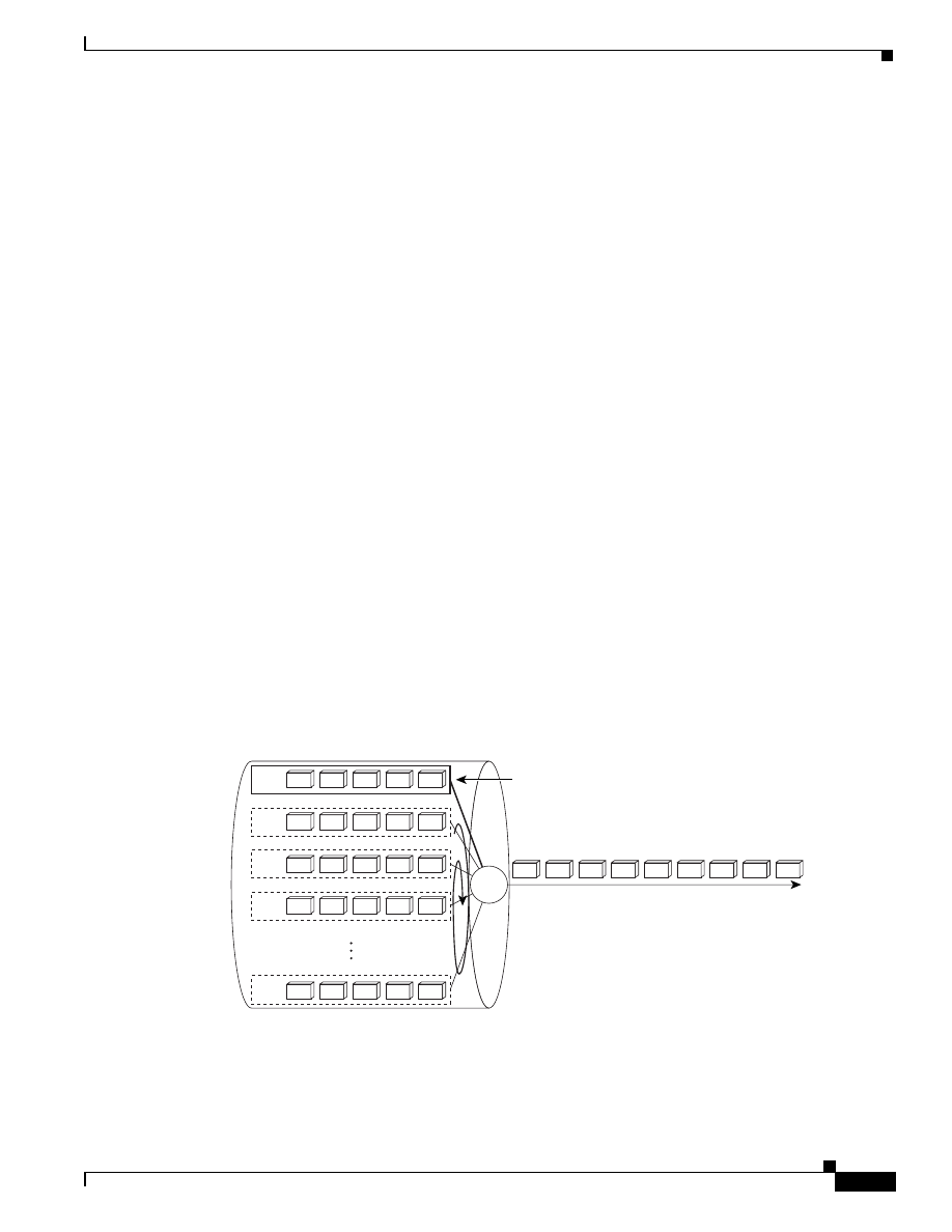
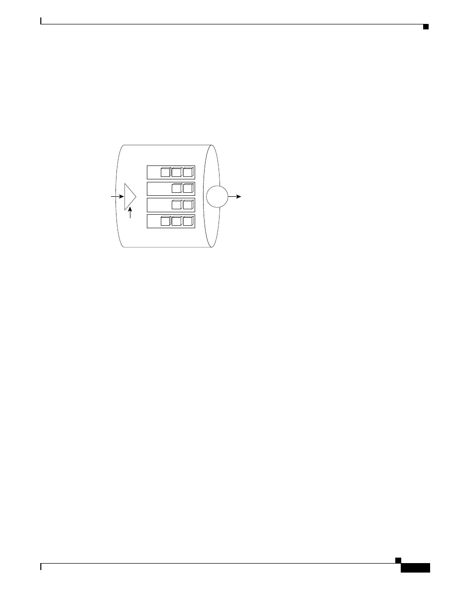
Figure 2-1 shows MDRR configured for strict priority mode. All voice packets (labeled 1) in the strict
priority LLHP queue used exclusively for VoIP are sent (exhaustively) before packets in the other eight
queues are serviced in round-robin fashion. In other words, when the LLHP VoIP queue is empty, the
other queues are serviced in round-robin fashion.
In Figure 2-1, all of the voice packets (labeled 1) in the LLHP queue will be serviced before any of the
packets in the other queues.
Figure 2-1
MDRR Strict Priority Mode
1
2
3
4
5
1
1
1
1
MDRR
LLHP queue used for VoIP packets
26514
1
1
1
1
1
2
2
2
2
2
3
3
3
3
3
4
4
4
4
4
8
8
8
8
8
2-6
Quality of Service for Voice over IP Solutions Guide
Version 1.0
Chapter 2
QoS Features for Voice over IP
Congestion Management
Alternate Priority Mode
Also referred to as fair priority, in this mode, service alternates between the LLHP queue and the CoS
queues. Packets are serviced from the LLHP queue and then from an active CoS queue that is selected
from among the CoS queues in round-robin fashion. This process of servicing the queues is
repeated—service alternates between the LLHP queue and the next CoS queue, the LLHP queue and
the next CoS queue, and so on—until the queues are empty. Alternate, or fair, priority mode does not
delay indefinitely delivery of traffic in the CoS queues, hence its name. The CoS queues are serviced
fairly in relation to one another, with the LLHP queue receiving alternating priority. This mode
guarantees that all queues are serviced but at the expense of some latency on the LLHP queue.
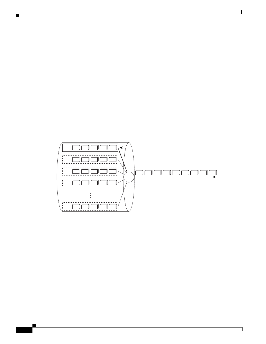
Figure 2-2 shows MDRR configured in alternate priority mode: a single VoIP packet, labeled 1,
enqueued in the LLHP queue, is serviced first, then a packet from queue 2, then another VoIP packet
from the LLHP queue followed by a packet from queue 3, then another VoIP packet from the LLHP
queue, then a packet from queue 4, and so on. Whenever the LLHP queue is not empty, its packets are
serviced in this fashion.
When VoIP packets are enqueued, service is returned to the LLHP queue. As you can see in Figure 2-2,
every other packet on the line is a voice packet.
Figure 2-2
MDRR Alternate Priority Mode
Advanced Concepts
Because it is difficult to scale up WFQ for high-speed transport links running at OC-3, OC-12, and
higher rates, MDRR, a variant of DRR, is implemented for the Cisco 12000 GSR router to support
delay-sensitive voice traffic.
This section gives explains how DDR works; then it explains how MDRR extends the functionality for
delay-sensitive traffic, such as voice. For complete information on how to configure MDRR, see the
Cisco IOS documentation.
For DRR to enact round robin fashion, each queue has assigned to it a configurable value called a
service quantum. A service quantum provides a measure of how much traffic should be handled from
the queue in each round. Packets from that queue are serviced until their cumulative length (byte count)
exceeds the service quantum.
A deficit counter, which is a memory mechanism designed to enhance fairness and packet size
independence, is used as a credit mechanism. The deficit counter value is added to the service quantum
to determine the measure of service available for each queue during each round. For example, given the
1
4
1
5
1
1
2
1
3
MDRR
LLHP queue used for VoIP packets
26515
1
1
1
1
1
2
2
2
2
2
3
3
3
3
3
4
4
4
4
4
8
8
8
8
8

2-7
Quality of Service for Voice over IP Solutions Guide
Version 1.0
Chapter 2
QoS Features for Voice over IP
Congestion Management
round-robin algorithm described later in this section, in a particular round a queue may not be able to
get a full quantum worth of service because the next packet to be dequeued is larger than the remaining
amount allowed to be serviced as specified by the remaining quantum. In this example, the deficit is
used in addition to the quantum the next time the queue is serviced.
These are the basic steps that define how DRR works:
1.
Packets are classified based on IP precedence and inserted in the appropriate queues.
2.
Active queues are serviced in round-robin order:
a.
Deficit counter values for each queue are initialized to 0.
b.
The configured quantum size is added to the deficit counter of the first queue. The first packet
in the first queue is dequeued and the deficit counter is decremented. This process repeats until
the queue is empty or the deficit counter goes negative. A full packet is serviced even if the
deficit counter runs out during the processing. If there is a remaining deficit, it is added to the
quantum to be used to service the queue next round.
c.
The process described in Step b is repeated for this queue and so on, for each successive queue.
If the receive (input) interface is an engine 0 card, for example, which supports up to 16 slots
depending on the type of chassis used, there are 8 queues per slot. On the transmit (output) side,
there are 8 queues per interface. For each set of 8 queues, you can configure whether the LLHP
queue is used in strict priority mode or alternate priority mode. Data is sorted and enqueued
from the receive queue to the appropriate transmit queue. MDRR maps IP traffic to different
CoS. That is, it enqueues packets based on the IP precedence value of the packet.
These are the basic steps that define how MDRR works as a modification to DRR:
1.
If MDRR is configured for high priority mode and the LLHP queue contains packets, MDRR
services that queue first. If MDRR is configured for fair priority mode, a queue other than the LLHP
queue was last serviced, and the LLHP queue contains packets, then the LLHP queue is serviced
first; if the LLHP queue is empty, then the next active CoS queue in round-robin fashion is serviced.
2.
The deficit counter for the queue is incremented for the queue to be serviced.
3.
Packets from the queue are serviced until the until the queue is empty or the deficit counter goes
negative. The remaining deficit, if any, is added to the quantum to be used to service the queue next
round.
4.
The process described in Step 3. is repeated for this queue and so on, for each successive queue.
WRR
WRR is a packet queueing and scheduling algorithm used on the Catalyst 8500 series switches. It
provides class differentiation, bandwidth allocation, and delay bounding— features that make it
possible to give voice packets premium service, although not strict priority. WRR interprets IP
Precedence to assess how packets are classified. (You cannot use WRR to mark or change the IP
Precedence of a packet.)
Overview
WRR queues and schedules packets at the campus backbone on Catalyst 8500 series switches. WRR
interprets the ToS field of the IP header of the packet and enqueues packets based on the ToS value.
Unlike WFQ, which recognizes seven IP Precedence categories, WRR classifies packets into four
categories based on the first two (most significant, high-order) bits of the ToS field. WRR reserves four
associated queues for enqueuing packets belonging to these four classes.

2-8
Quality of Service for Voice over IP Solutions Guide
Version 1.0
Chapter 2
QoS Features for Voice over IP
Congestion Management
Packets sent to a core Catalyst 8500 switch have been previously marked for IP Precedence at the edge
of the network. For instance, in the example topology used in this guide, the IP Precedence for voice
packets delivered to a Catalyst 8500 at the core might be marked at the edge using Cisco IP phones.
Table 2-2 shows how WRR running on the Catalyst 8500 series switches uses the IP Precedence bits,
mapping them into four categories, each of which has its own transmission queue.
WRR does not explicitly reserve bandwidth for each of these four queues. Rather, each queue is
assigned a different WRR scheduling weight, which determines the way the queues share the interface
bandwidth.
Although you cannot mark the IP Precedence value of a packet, you can use WRR to configure the
weight assigned to a specific class of traffic, such as the traffic class to which voice packets are assigned,
in order to give priority treatment to that traffic. In assigning IP Precedence to packets, we recommend
that an IP Precedence of 5 be assigned to voice packets. WRR would interpret an IP Precedence of 5 to
mean that voice packets should be enqueued to the second WRR queue (queue 2). You can improve the
service that WRR gives to voice traffic by using WRR to give voice packets a weight. Packets with a
weight of 8 are enqueued to the third WRR queue (queue 3), which gets the highest priority service from
WRR.
Table 2-3 shows the default weight assignments to the WRR queues.
In configuring WRR, you can assign a different weight to each queue. For WRR, the higher the weight
assigned to a queue, the higher the effective bandwidth attributed to that particular queue. This
relationship of weight to bandwidth is different from that of WFQ in which a lower weight gets a higher
precedence and, thus, more bandwidth. Considering the effect of weight, you can better ensure that
Table 2-2
IP Precedence and Associated WRR Queues
IP Precedence
Value
IP Precedence
Bits
Delay Priority
Associated
Queue
0
0 0 0
0 0
Q-0
1
0 0 1
0 0
Q-0
2
0 1 0
0 1
Q-1
3
0 1 1
0 1
Q-1
4
1 0 0
1 0
Q-2
5
1 0 1
1 0
Q-2
6
1 1 0
1 1
Q-3
7
1 1 1
1 1
Q-3
Table 2-3
Default WRR Weight Assignments
WRR Queues
Weight
0
1
1
2
2
4
3
8
2-9
Quality of Service for Voice over IP Solutions Guide
Version 1.0
Chapter 2
QoS Features for Voice over IP
Congestion Management
voice traffic receives premium treatment by assigning a high weight to the queue used for voice packets.
Given that voice packets marked with an IP Precedence of 5 are enqueued to WRR queue 2, you should
assign a WRR weight of 8 to WRR queue 2.
You can use the following formula to determine the effective bandwidth in megabits per second (Mbps)
for a particular queue:
(W / S) x B = number mbps
where:
•
W = WRR weight of the specified queue.
•
S = Sum of the weight of all active queues on the outgoing interface.
•
B = Available bandwidth in Mbps.
The weight for any queue is 0 to 15. However, the sum of the WRR weight for all four queues on an
interface cannot exceed 15. If the total weight exceeds 15, most the bandwidth of the interface is
exceeded.
Advanced Concepts
The WRR scheduler has two main responsibilities within the Catalyst 8500 switch:
•
To schedule frames into the switching fabric based on the priority queue being requested.
•
To schedule frames out of the switching fabric based on the WRR scheduling algorithm.
As stated previously, you can assign different WRR-scheduling weights to the queues to determine the
way bandwidth is to be shared among the queues. Use of weights allows you to provide bandwidth to
higher priority applications such as voice based on the IP Precedence of the packet, while fairly granting
access to lower priority queues. When queues are weighted and congestion occurs, the WRR schedule
affords each queue the bandwidth allotted to it based on its weight.
You can configure the mapping between queues and weights at both the system and interface levels. As
is customary, interface-level configuration takes precedence over system-level configuration.
When there is no network congestion, all queues between any pair of interfaces are granted the same
weight, and bandwidth is not explicitly reserved for them. Under these circumstances, WRR and the
weights provided do not strongly influence how packets are switched out the fabric because there is
sufficient bandwidth available. However, WRR scheduling becomes increasingly important when an
outgoing interface is congested.
When a link is congested, WRR services each queue per port based on the priority determined by the
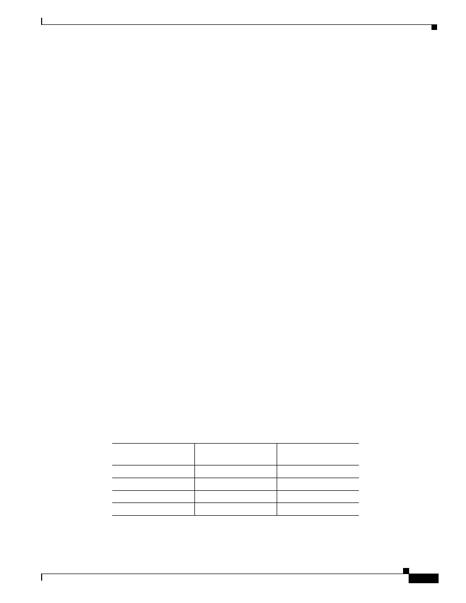
configured weight. Consider, for example, the weights assigned by a network manager in Table 2-4.
Based on these priorities and weights, WRR services QoS-3 more often.
Table 2-4
Sample WRR Priority Weights and Bandwidth
Quality of Service
Priority/Queue
Weight Given by
Network Manager
Bandwidth Assignment
QoS-0
1
=(1/(8+4+2+1)) x 100
QoS-1
2
=((2/(8+4+2+1)) x 100
QoS-2
3
=((3/(8+4+2+1)) x 100
QoS-3
4
=((4/(8+4+2+1)) x 100
2-10
Quality of Service for Voice over IP Solutions Guide
Version 1.0
Chapter 2
QoS Features for Voice over IP
Congestion Management
WFQ
WFQ is a congestion management algorithm that provides priority management, but not strict
prioritization for voice, during periods of traffic congestion. WFQ offers a solution that provides
consistent, fair response time, based on weights, to heavy and light traffic alike without adding
excessive bandwidth. WFQ provides features such as traffic isolation and delay bandwidth guarantees.
Implicit within WFQ is a strict priority queue that is created when WFQ is enabled. However, this queue
cannot be used until the IP RTP Priority feature is enabled.
Note
Because they do not provide the strict priority required by voice traffic, WFQ and DWFQ
largely are not useful for voice applications. For conditions under which you should use
them for voice traffic, see the “How Do WFQ, DWFQ, and CBWFQ Apply to Voice
Traffic?” section in this chapter.
There are two kinds of WFQ:
•
Flow-Based WFQ
•
CBWFQ
Before either of these WFQ types is discussed, this section explains IP Precedence and its use.
IP Precedence
Packet classification is pivotal to techniques that select packets traversing a network element or a
particular interface for different types of QoS service. One method of classifying traffic is to mark it
with IP Precedence values. IP Precedence allows you to specify the CoS for a packet using the three
precedence bits in the ToS field of the IPv4 header. Figure 2-3 shows the ToS field within the structure
of the IP packet.
Figure 2-3
IPv4 Packet ToS Field
How It Works
Using the ToS bits, you can define up to eight classes of service. Other features configured throughout
the network can then use these bits to determine how to treat the packet in regard to the type of service
to grant it. These other QoS features can assign appropriate traffic-handling policies including
congestion management strategy and bandwidth allocation. For example, although IP Precedence is not
a queueing method, queueing methods WFQ and WRED can use the IP Precedence setting of the packet
to prioritize traffic.
27947
Data
3-bit precedence
IPv4 packet
ToS field

2-11
Quality of Service for Voice over IP Solutions Guide
Version 1.0
Chapter 2
QoS Features for Voice over IP
Congestion Management
By setting precedence levels on incoming traffic and using precedence values in combination with the
Cisco IOS QoS queueing features for VoIP, you can create differentiated service. You can use BGP
Policy Propagation and Cisco IP phones to set the precedence for VoIP traffic to 5, giving it the highest
priority.
Note
Even if you plan to use strict priority mode features such as IP RTP Priority and priority
queueing within CBWFQ, you should set precedence on voice flows that will traverse an
internetwork. This approach is recommended because IP Precedence values are persistent;
that is, the voice packet carries the value throughout the internetwork. Some platforms
such as the GSR, which is used extensively within the core of many networks, do not
support strict priority and may relay on IP Precedence for classification and packet
differentiation. For this reason, it is always beneficial to give voice traffic an IP Precedence
of 5.
So that each subsequent network element can provide service based on the determined policy, IP
Precedence is usually deployed as close to the edge of the network or the administrative domain as
possible. You can think of IP Precedence as an edge function that allows core (or backbone) QoS
features, such as WRED, to forward traffic based on CoS. IP Precedence can be used to control the
dequeueing and scheduling behavior of WFQ.
IP Precedence can be mapped into adjacent technologies, such as ATM or Frame Relay. The Cisco IOS
QoS IP to ATM CoS feature, described in the “IP to ATM CoS” section on page 2-44, relies on this
capability.
Weights and Bandwidth
In considering class weights, it is helpful to think of them as inversely proportional to the class
bandwidths. Therefore, the lower the weight, the greater the bandwidth and better the service given to
the class.
Based on the way weights are assessed, each class receives at least 95 percent of the bandwidth
configured for it, given the amount of bandwidth assigned to a class is within legal bounds not to exceed
75 percent of the interface bandwidth.
Flow-Based WFQ
Flow-based WFQ, referred to henceforth in this guide as WFQ, is enabled by default on links with
speeds of 2 Mbps or less.Without requiring configuration or analysis or that you first define access lists,
WFQ automatically sorts among individual traffic streams and categorizes traffic into two kinds of
flows: high-bandwidth sessions and low-bandwidth sessions.
WFQ is IP Precedence-aware, meaning that it is able to detect higher priority packets designated by IP
Precedence, give them superior response time, and schedule them for faster transmission than other
packets. Voice packets are usually assigned a high precedence (Precedence 5) and thus WFQ gives voice
traffic better service than data traffic.
WFQ dynamically adapts to changing network traffic conditions. It offers a solution that provides
consistent, fair response time, based on weights, to heavy and light traffic alike without adding
excessive bandwidth.
WFQ does not distinguish flows by their type, such as Telnet, voice, Systems Network Architecture
(SNA), or File Transfer Protocol (FTP). Rather, it categorizes traffic by its flow characteristics,
dynamically sorting traffic into messages that make up a conversation. WFQ classifies traffic into
different flows based on packet header addressing, using such characteristics as source IP address,
2-12
Quality of Service for Voice over IP Solutions Guide
Version 1.0
Chapter 2
QoS Features for Voice over IP
Congestion Management
destination IP address, source or destination Transmission Control Protocol (TCP) or User Datagram
Protocol (UDP) port, MAC address, Frame Relay data-link connection identifier (DLCI) value, and ToS
value.
You can think of standard WFQ as fair queueing with the addition of weights:
•
It supports per-flow queueing—each flow is relegated to a separate queue.
•
It applies weights, or priorities, to identified traffic flows to determine how much bandwidth each
conversation is allowed relative to other conversations. The weight that WFQ assigns to a flow
determines the transmit order for packets queued in that flow.
•
It breaks up the train of packets within a conversation to ensure that bandwidth is shared fairly
between individual conversations and that low-volume traffic is transferred in a timely fashion.
•
It grants low-bandwidth (low-volume) traffic effective priority over high-bandwidth (high-volume)
traffic, and high-bandwidth traffic shares the transmission service proportionally according to
assigned weights.
WFQ apportions bandwidth based on weight. Thus, it does not allow you to guarantee bandwidth
for voice applications. WFQ simultaneously schedules interactive traffic such as voice packets to
the front of a queue to reduce response time and fairly shares the remaining bandwidth among
high-bandwidth flows. Low-bandwidth voice traffic streams receive preferential service, sending
their entire offered loads in a timely fashion.
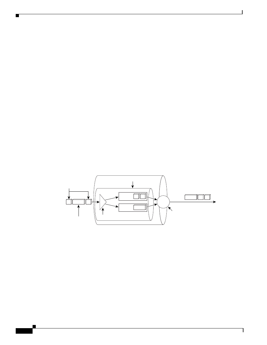
Figure 2-4 shows two flows. In this figure, the voice packets are 100-byte packets; they are smaller than
the data packets, which are 200-byte data packets. To fairly schedule the packets for transmission and
give equal bandwidth, WFQ sends two voice packets for each single data packet.
Figure 2-4
WFQ Classification and Scheduling
WFQ addresses the problem of round-trip delay variability. If multiple high-bandwidth conversations
are active, their transfer rates and interarrival periods are made much more predictable, resulting in
more predictable throughput and response time for each active flow.
Advanced Concepts
WFQ manages simplex data streams, such as voice, and duplex data streams such as those between pairs
of applications.WFQ segregates traffic into flows and then schedules traffic onto the outputs to meet
specified bandwidth allocation or delay bounds.
WFQ cooperates with the RSVP and IP Precedence Cisco IOS software scheduling techniques in the
following manner:
•
RSVP uses WFQ to allocate buffer space, schedule packets, and guarantee bandwidth for reserved
flows. WFQ works with RSVP to help provide differentiated and guaranteed QoS services.
1
2
2
1
2
1
1
Two 100-byte
voice packets
Configurable queues
Transmit
scheduling
Classify
One 200-byte
data packet
Dequeue
27083
1
1

2-13
Quality of Service for Voice over IP Solutions Guide
Version 1.0
Chapter 2
QoS Features for Voice over IP
Congestion Management
•
WFQ is IP Precedence-aware. The IP Precedence field has values from 0 to 7. As the precedence
value increases, the WFQ allocates more bandwidth to that conversation to make sure that it gets
served more quickly when congestion occurs.
In the weighting scheme for WFQ, lower weights are served first. IP Precedence serves as a divisor to
this weighting factor. For instance, traffic with an IP Precedence field value of 7 gets a lower weight
than traffic with an IP Precedence field value of 3, and thus has priority in the transmit order.
CBWFQ
CBWFQ extends the standard WFQ functionality to provide support for user-defined traffic classes.
CBWFQ runs on Cisco 7200 series routers with NPE150 or higher for T1/E1/Ethernet rates or with
NPE200 or higher for T3 rates.
Note
Because they do not provide the strict priority required by voice traffic, WFQ and DWFQ
are not useful largely for voice applications. See the “How Do WFQ, DWFQ, and CBWFQ
Apply to Voice Traffic?” section.
Overview
CBWFQ allows you to define what constitutes a class based on criteria that exceed the confines of flow.
Using CBWFQ, you can create a specific class for voice traffic. CBWFQ allows you to use standard and
extended numbered access control lists and protocols or input interface names to define how traffic will
be classified, thereby providing coarser granularity. You need not maintain traffic classification on a
flow basis.
The classes you create determine how packets are grouped in queues. CBWFQ allows you to specify
the exact amount of bandwidth to be allocated for a specific class of traffic. Taking into account
available bandwidth on the interface, you can configure up to 64 classes and control distribution among
them. (This is not the case with WFQ. For WFQ, weights determine how much bandwidth each
conversation is allowed relative to other conversations, and the weights and traffic classification are
dependent on and limited to the 7 IP Precedence levels.)
For CBWFQ, each class is associated with a separate queue. You can allocate a specific minimum
amount of guaranteed bandwidth to the class as a percentage of the link or in kbps. Bandwidth not used
can be shared by other classes in proportion to their assigned weights. When configuring CBWFQ, you
should consider that bandwidth allocation does not necessarily mean that the traffic belonging to a class
will experience low delay; however, you can skew weights to simulate priority queueing.
Packets satisfying the match criteria for a class constitute the traffic for that class. A queue is reserved
for each class, and traffic belonging to a class is directed to the queue of that class.
Figure 2-5 shows two queues, the first of which is for voice traffic. Any packet with an IP Precedence
of 5 is assigned to the voice class and gets a minimum of 80 kbps of bandwidth on the 128-kbps link.
2-14
Quality of Service for Voice over IP Solutions Guide
Version 1.0
Chapter 2
QoS Features for Voice over IP
Congestion Management
Figure 2-5
Example Queues for CBWFQ Classes
For CBWFQ, the weight specified for the class becomes the weight of each packet that meets the match
criteria of the class. Packets that arrive at the output interface are classified according to the match
criteria filters you define, then each one is assigned the appropriate weight. The weight for a packet
belonging to a specific class is derived from the bandwidth you assigned to the class when you
configured it; in this sense the weight for a class is user-configurable.
After the weight of a packet is assigned, the packet is enqueued in the appropriate class queue. CBWFQ
uses the weights assigned to the queued packets to ensure that the class queue is serviced fairly.
Configuring a class policy—and, thus, configuring CBWFQ—entails these processes:
•
Defining traffic classes to specify the classification policy (class maps).
This process determines how many types of packets are to be differentiated from one another.
•
Associating policies—that is class characteristics—with each traffic class (policy maps).
This process entails configuration of policies to be applied to packets belonging to one of the
classes previously defined through a class map. For this process, you configure a policy map that
specifies the policy for each traffic class.
•
Attaching policies to interfaces (service policies).
This process requires that you associate an existing policy map, or service policy, with an interface
to apply the particular set of policies of the map to that interface.
Advanced Concepts
Once a class has been defined according to its match criteria, you can assign it characteristics. To
characterize a class, you assign it bandwidth, weight, and maximum packet limit. The bandwidth
assigned to a class is the minimum bandwidth delivered to the class during congestion.
To characterize a class, you also specify the queue limit for that class, which is the maximum number
of packets allowed to accumulate in the queue of the class. Packets belonging to a class are subject to
the bandwidth and queue limits that characterize the class.
After a queue has reached its configured queue limit, enqueuing of additional packets to the class causes
tail drop or packet drop to take effect, depending on how class policy is configured.
Tail drop is used for CBWFQ classes unless you explicitly configure policy for a class to use WRED to
drop packets as a means of avoiding congestion. You can apply WRED on a per-class basis. Note that
if you use WRED packet drop instead of tail drop for one or more classes comprising a policy map, you
must ensure that WRED is not configured for the interface to which you attach that service policy.
Class map voice = 80 kbps
Class map data = 48 kbps
128 kbps
Classify
Dequeue
27084
1
2
2
1
2
1
2
2
1
1

2-15
Quality of Service for Voice over IP Solutions Guide
Version 1.0
Chapter 2
QoS Features for Voice over IP
Congestion Management
If a default class is configured, all unclassified traffic is treated as belonging to the default class. If no
default class is configured, then by default the traffic that does not match any of the configured classes
is flow classified and given best-effort treatment. Once a packet is classified, all of the standard
mechanisms that can be used to differentiate service among the classes apply.
CBWFQ and WFQ are mutually exclusive, as are CBWFQ and WRED, and these rules apply:
•
Attaching a service policy to an interface disables WFQ on that interface if WFQ is configured for
the interface. For this reason, you should ensure that WFQ is not enabled on such an interface.
•
Attaching a service policy containing classes configured to use WRED to an interface disables
WRED on that interface. If any of the classes that you configure in a policy map use WRED for
packet drop instead of tail drop, you must ensure that WRED is not configured on the interface to
which you intend to attach that service policy.
DWFQ
DWFQ provides bandwidth allocations and delay bounds to specified IP traffic sources by segregating
the traffic into flows or classes and then providing first-in, first-out (FIFO) service to the various queues
according to their assigned weights.
Note
Because they do not provide the strict priority required by voice traffic, WFQ and DWFQ
largely are not useful for voice applications. For conditions under which you should use
them for voice traffic, see the “How Do WFQ, DWFQ, and CBWFQ Apply to Voice
Traffic?” section.
There are three kinds of DWFQ:
•
Flow-Based DWFQ
•
QoS Group-Based DWFQ
•
ToS-Based DWFQ
To use any type of DWFQ, dCEF switching must be enabled on the interface. These features require a
use of Versatile Interface Processor (VIP) 2-40 or later. DWFQ features cannot be configured on
subinterfaces.
Note
dCEF is an advanced Layer 3 IP forwarding technology designed to optimize network
performance and scalability. It is a switching paradigm that is thought of as a full
topology-driven architecture because it uses the first packet in a flow to build an IP
destination cache to be used by packets subsequently delivered to the same network
destination. The dCEF feature uses all available routing information to build an IP
Forwarding Information Base (FIB) so that a deterministic switching decision can be
made, even for the first packet to a new destination. This capability is significant, given
the changing traffic dynamics on the Internet and within enterprise intranets, where flows
are increasingly of shorter duration and more topologically dispersed, such as Web traffic.
Flow-Based DWFQ
For flow-based DWFQ, packets are classified by flow. Packets with the same source IP address,
destination IP address, source TCP or UDP port, destination TCP or UDP port, protocol, and ToS fields
belong to the same flow.
2-16
Quality of Service for Voice over IP Solutions Guide
Version 1.0
Chapter 2
QoS Features for Voice over IP
Congestion Management
Each flow corresponds to a separate output queue. When a packet is assigned to a flow, it is placed in
the queue for that flow. During periods of congestion, WFQ allocates an equal share of the bandwidth
to each active queue. All flows are equally weighted. Flow-based DWFQ uses fair queueing, therefore
packets do not get priority treatment based on IP Precedence.
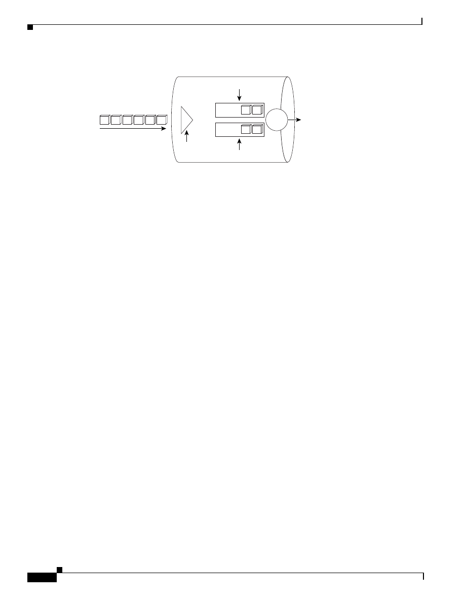
Figure 2-6 shows six flow-based queues. There is one queue per flow. Flow-based DWFQ is fair
queueing; priority is not determined by IP Precedence values.
Figure 2-6
Flow-Based Distributed Weighted Fair Queueing
QoS Group-Based DWFQ
For QoS group-based DWFQ, packets are assigned to different queues by policy routing based on their
QoS group or the IP Precedence in the ToS field. A QoS group is an internal classification of packets
used by the router to determine how certain QoS features, such as WFQ and CAR, treat packets.You
can use QoS policy propagation via BGP to assign packets to QoS groups.
For QoS Group-Based DWFQ, you can specify a weight for each class. In periods of congestion, each
group is allocated a percentage of the output bandwidth equal to the weight of the class. For example,
if a class is assigned a weight of 50, packets from this class will be allocated at least 50 percent of the
outgoing bandwidth during periods of congestion. When the interface is not congested, queues can use
any available bandwidth.
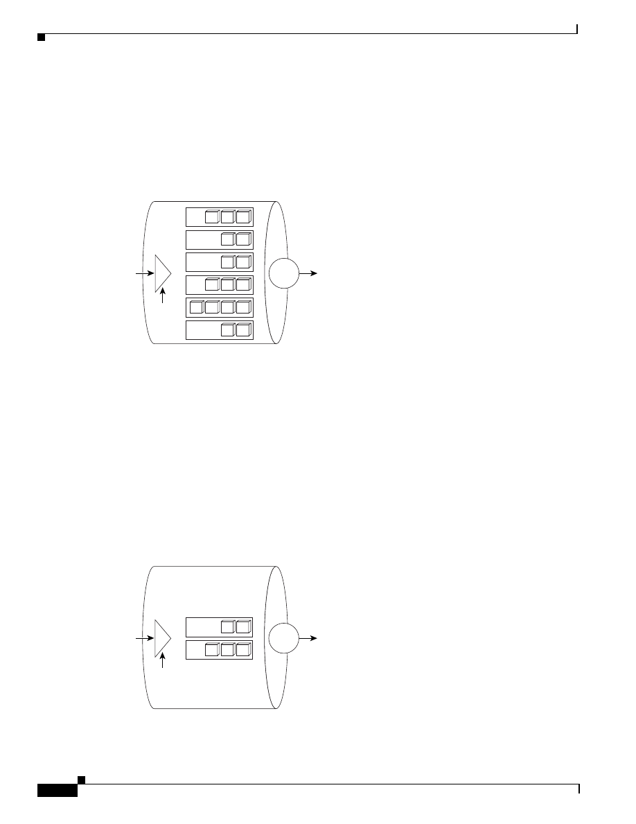
Figure 2-7 shows two QoS group-based queues.
Figure 2-7
QoS Group-Based DWFQ
Classify
27085
1
1
1
2
2
3
3
4
4
4
5
5
5
5
6
6
Dequeue
Classify
27086
1
1
2
2
2
Dequeue
2-17
Quality of Service for Voice over IP Solutions Guide
Version 1.0
Chapter 2
QoS Features for Voice over IP
Congestion Management
ToS-Based DWFQ
For ToS-based DWFQ, packets are classified based on only the two low-order IP Precedence bits, the
last two bits. ToS-based DWFQ supports four queues. You assign weights to the four queues using
percentages.
Figure 2-8 shows the four ToS-based DWFQ queues.
Figure 2-8
ToS-Based DWFQ
IP RTP Priority
When WFQ is enabled, it creates a strict priority queue whose use is not available until the IP RTP
Priority feature is configured to enable it. The IP RTP Priority feature enables use of this queue.
Introduced in Cisco IOS Release 12.0(5)T, the IP RTP Priority feature allows you to specify a range of
UDP/RTP ports whose voice traffic is guaranteed strict priority service over any other queues or classes
using the same output interface. Strict priority means that if packets exist in the priority queue, they are
dequeued and sent first—that is, before packets in other queues are dequeued. The result is that voice
is given strict priority service in preference to other nonvoice traffic.
For Release 12.0(7)T and later, you can use the priority queueing within CBWFQ feature, which allows
you to configure the strict priority queueing for voice traffic belonging to a class. Without use of IP RTP
Priority, CBWFQ provides true WFQ based on defined classes with no strict priority queue available
for real-time traffic.
The IP RTP Priority feature does not require that you know the port of a voice call. Rather, the feature
gives you the ability to identify a range of ports whose traffic is put into a single priority queue.
Moreover, you can specify the entire voice port range—16384 to 32767—to ensure that all voice traffic
is given strict priority service. IP RTP Priority is especially useful on slow-speed links whose speed is
less than 1.544 Mbps.
Figure 2-9 shows five queues configured for IP RTP Priority. The priority queue, the high queue, is
dedicated to voice traffic; the entire contents of the priority queue are scheduled for transmission before
any other queues are serviced. (The strict priority process is also referred to as exhaustive queueing.)
Once the priority queue is empty, the other queues are serviced using WFQ.
Classify
27087
1
1
2
2
3
3
1
4
4
4
Dequeue
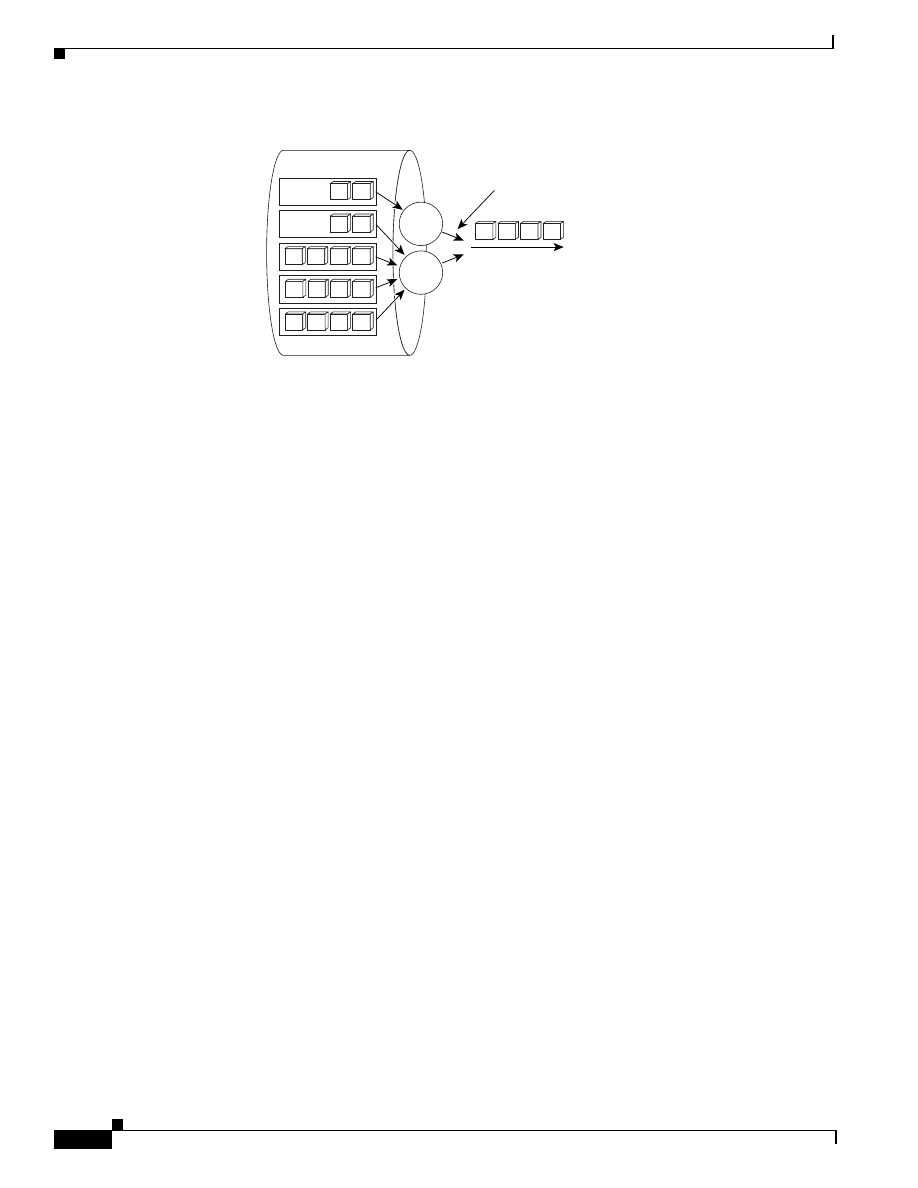
2-18
Quality of Service for Voice over IP Solutions Guide
Version 1.0
Chapter 2
QoS Features for Voice over IP
Congestion Management
Figure 2-9
IP RTP Priority
You can use IP RTP Priority in conjunction with either WFQ or CBWFQ on the same outgoing interface.
In either case, traffic matching the range of ports specified for the priority queue is guaranteed strict
priority over other CBWFQ classes or WFQ flows; voice packets in the priority queue are all and always
serviced first. Here is how the other classes and queues are handled after the priority queue is serviced:
•
When used in conjunction with WFQ, the ip rtp priority command provides strict priority to voice,
and WFQ scheduling is applied to the remaining queues.
•
When used in conjunction with CBWFQ, the ip rtp priority command provides strict priority to
voice. CBWFQ can be used to set up classes for other types of traffic (such as SNA) that need
dedicated bandwidth and need to be treated better than best effort and not as strict priority; the
nonvoice traffic is serviced fairly based on the weights assigned to the enqueued packets. CBWFQ
can also support flow-based WFQ within the default CBWFQ class if so configured.
Because voice packets are small in size and can be detained between large data packets sent out the same
interface, you should use Link Fragmentation and Interleaving (LFI) on slow-speed PPP links and FRF.12
on slow-speed Frame Relay links. (When you enable LFI or FRF.12, large data packets are fragmented and
the small voice packets are interleaved between the data fragments. LFI and FRF.12 help to prevent voice
packet delay.)
If you want to understand its behavior and properly use the IP RTP Priority feature, it is important to
consider its admission control and policing characteristics. When you use the ip rtp priority command
to configure the priority queue for voice, you specify a strict bandwidth limitation. The specified
amount of bandwidth and no more is guaranteed to voice traffic enqueued in the priority queue. (This
is the case whether you use the IP RTP Priority feature with CBWFQ or WFQ.)
IP RTP Priority closely polices use of bandwidth for the priority queue, ensuring that the allocated
amount is not exceeded. In fact, IP RTP Priority polices the flow every second. IP RTP Priority prohibits
transmission of additional packets once the allocated bandwidth is consumed. If it discovers that the
configured amount of bandwidth is exceeded, IP RTP Priority will drop packets, an event that is poorly
tolerated by voice traffic. Close policing allows for fair treatment of other data packets enqueued in
other CBWFQ or WFQ queues.
You should also consider that the IP RTP Priority admission control policy disregards voice packet
compression (IP RTP Priority does not take Compressed Real-Time Protocol (CRTP) compression into
account). Suppose you use priority queueing within CBWFQ and you reserve 24-kbps bandwidth for
the voice priority queue, but the voice packets are compressed and compression reduces the flow to 12
kbps. In this case, admission control would not double the number of voice packets it would let through.
Rather, the unused bandwidth would be distributed among the other CBWFQ classes. This precept also
holds true for use of IP RTP Priority with WFQ.
VoIP (high)
Data (low)
Data (low)
Data (low)
Data (low)
Exhaustive
queueing
5
3
1
1
27089
2
2
3
3
3
3
4
4
5
5
5
4
4
5
1
1
WFQ
PQ

2-19
Quality of Service for Voice over IP Solutions Guide
Version 1.0
Chapter 2
QoS Features for Voice over IP
Congestion Management
The IP RTP Priority bandwidth management feature stipulates that the sum of all bandwidth allocation
for voice and data flows on the interface is not to exceed 75 percent of the total available bandwidth.
The remaining 25 percent of bandwidth is used for other overhead, including the Layer 2 header.
Typically, you apportion the 75 percent of available bandwidth to all classes and flows, including the
CBWFQ voice class assigned the priority queue or the WFQ voice flow that uses the priority queue.
Bandwidth allocation for voice packets takes into account the payload plus the IP, RTP, and UDP
headers—but, again, not the Layer 2 header. The remaining 25 percent of bandwidth that is used for
other overhead includes the Layer 2 header and best-effort traffic. Bandwidth for the CBWFQ default
class, for instance, is taken from the remaining 25 percent. Allowing 25 percent bandwidth for other
overhead is conservative and safe. On a PPP link, for instance, overhead for Layer 2 headers assumes
4 kbps.
If you know how much bandwidth is required for additional overhead on a link, under aggressive
circumstances in which you want to give voice traffic as much bandwidth as possible, you can override
the 75 percent maximum allocation for the bandwidth sum allocated to all classes or flows. The IP RTP
Priority feature includes a command called max-reserved-bandwidth that you can use to override the
75 percent limitation. If you override the fixed amount of bandwidth, exercise caution and ensure that
you allow enough remaining bandwidth to support best-effort and control traffic.
An another alternative, if the importance of voice traffic far exceeds that of data, is that you can allocate
most of the 75 percent bandwidth used for flows and classes to the voice priority queue. Unused
bandwidth at any given point is made available to the other flows or classes.
Because the ip rtp priority gives absolute priority over other traffic, it should be used with care. If the
traffic exceeds the configured bandwidth, then all the excess traffic is dropped.
The IP RTP Priority feature runs on these platforms:
•
Cisco 1003
•
Cisco 1004
•
Cisco 1005
•
Cisco 1600 series
•
Cisco 2500 series
•
Cisco 2600 series
•
Cisco 3600 series
•
Cisco 3800 series
•
Cisco 4000 series (Cisco 4000, 4000-M, 4500, 4500-M, 4700, 4700-M)
•
Cisco 5200 series
•
Cisco AS5300
•
Cisco 7000 series
•
Cisco 7200 series
•
Cisco 7500 series
Priority Queueing within CBWFQ
The priority queueing within CBWFQ feature brings the strict priority queueing functionality of IP RTP
Priority required for delay-sensitive, real-time traffic, such as voice, to CBWFQ. Priority queueing
within CBWFQ allows for use of a strict priority queue created when WFQ is enabled but not available
for use until CBWFQ is enabled. Although it is possible to enqueue various types of real-time traffic to

2-20
Quality of Service for Voice over IP Solutions Guide
Version 1.0
Chapter 2
QoS Features for Voice over IP
Congestion Management
the strict priority queue, we strongly recommend that you direct only voice traffic to it. This
recommendation is made because voice traffic is well-behaved, whereas other types of real-time traffic
are not. Moreover, voice traffic requires that delay be nonvariable in order to avoid jitter. Other real-time
traffic such as video could introduce variation in delay thereby thwarting the constancy of delay
required by voice traffic. Priority queueing within CBWFQ satisfies the criteria for and implements the
extended forwarding functionality of distributed services.
Priority queueing within CBWFQ allows for a broad range of ways in which to specify the traffic to be
guaranteed strict priority delivery. To indicate the voice flow to be enqueued to the strict priority queue,
you are not limited to use of the UDP port range as you are with IP RTP Priority. Rather, you can use
all of the mechanisms implicit to class definition: you can match on access lists, protocols, input
interfaces as well as IP Distributed Services Code Point (DSCP) values.
To understand how priority queueing within CBWFQ works, it helps to consider certain aspects of the
combined features—the IP RTP Priority feature and the CBWFQ feature—and then to consider how
they are used together, including the few differences introduced when strict priority queueing for
delay-sensitive traffic is applied to a CBWFQ class within a policy map. This section takes that
approach.
About CBWFQ and Strict Priority
Without use of IP RTP Priority, CBWFQ provides true WFQ based on defined classes with no strict
priority queue available for real-time traffic.
Recall that CBWFQ has two main parts:
•
Named classes, which you set up and which are mapped to existing entities such as protocols,
access control lists (ACLs), or input interfaces.
•
Policy maps, which you define to include one or more classes. After you specify a class within the
policy map, you assign it values, such as the bandwidth available for its traffic and the individual
queue limit.
Packets satisfying the match criteria for a class constitute the traffic for that class. A queue is reserved
for each class, and traffic belonging to a class is directed to the queue of that class.
For CBWFQ, the weight assigned to the packets of a class determines the order in which packets are
sent. All packets are serviced fairly based on weight; no class of packets may be granted strict priority.
This scheme poses problems for voice traffic which is largely intolerant of delay, especially variation
in delay. (For voice traffic, variations in delay introduce irregularities of transmission manifesting as
jitter in the heard conversation.)
The priority command, which configures the IP RTP Priority feature for a CBWFQ class, enables use
of a single, strict priority queue within CBWFQ at the class level. Priority queueing within CBWFQ
allows you to direct traffic belonging to a class to the WFQ strict priority queue. To enqueue class traffic
to the strict priority queue, you configure the priority command for the class after you specify the
named class within a policy map. (Classes to which the priority command is applied are considered
priority classes.) Within a policy map, you can give one or more classes priority status. When multiple
classes within a single policy map are configured as priority classes, all traffic from these classes is
enqueued to the same, single, strict priority queue.
One way in which the IP RTP Priority feature used within CBWFQ differs from its use outside CBWFQ
is in the parameters it takes. Outside CBWFQ, you specify the range of UDP ports whose voice traffic
flows are to be given priority service. Because you can configure the priority status for a class within
CBWFQ, you are no longer limited to a UDP port name to stipulate priority flows. Instead, all of the
valid match criteria used to specify traffic for a class now applies to priority traffic. These methods of

2-21
Quality of Service for Voice over IP Solutions Guide
Version 1.0
Chapter 2
QoS Features for Voice over IP
Congestion Management
specifying traffic for a class include matching on access lists, protocols, and input interfaces. Moreover,
within an access list you can specify that traffic matches are allowed based on the IP DSCP value that
is set using the first six bits of the ToS byte in the IP header.
Guaranteed Bandwidth
When you specify the priority command for a class, it takes a bandwidth argument that gives bandwidth
in kbps. You use this parameter to specify the amount of bandwidth allocated for packets belonging to
the class configured with the priority command. The bandwidth parameter both guarantees bandwidth
to the priority class and restrains the flow of packets from the priority class.
When the bandwidth is exceeded, tail drop is used to drop packets. Voice traffic enqueued to the priority
queue is UDP-based and therefore not adaptive to the early packet drop characteristic of WRED.
Because WRED is ineffective, you cannot use the WRED random-detect command with the priority
command.
When congestion occurs, traffic destined for the priority queue is metered to ensure that the bandwidth
allocation configured for the class to which the traffic belongs is not exceeded.
Priority traffic metering has the following features:
•
It is much like the rate limiting in CAR, except that priority traffic metering is only performed under
congestion conditions.
•
It is performed on a per-packet basis and tokens are replenished as packets are sent. If not enough
tokens are available to send the packet, it is dropped.
•
It restrains priority traffic to its allocated bandwidth to ensure that nonpriority traffic, such as
routing packets and other data, is not starved.
With metering, the classes are policed and rate-limited individually. That is, although a single policy
map might contain four priority classes, all of which are enqueued in a single priority queue, they are
each treated as separate flows with separate bandwidth allocations and constraints.
It is important to note that because bandwidth for the priority class is specified as a parameter to the
priority command, you cannot also configure the bandwidth command for a priority class. To do so is
a configuration violation that would only introduce confusion in relation to the amount of bandwidth to
allocate.
The bandwidth allocated for a priority queue always includes the Layer 2 encapsulation header.
However, it does not include other headers, such as ATM cell-tax overheads. Here are three primary
factors you must allow for:
•
When you calculate the amount of bandwidth to allocate for a given priority class, account for the
fact the Layer 2 headers are included.
•
When ATM is used, account for the fact that ATM cell-tax overhead is not included.
•
You must also allow bandwidth for the possibility of jitter introduced by routers in the voice path.
An Example
Consider this case that uses ATM. Suppose a voice stream of 60 bytes emitting 50 packets per second
is encoded using G.729. Prior to converting the voice stream to cells, the meter for the priority queue
used for the voice stream assesses the length of the packet after the L2 LLC headers have been added.
Given the 8-byte Layer 2 LLC header, the meter will take into account a 68-byte packet. Because ATM
cells are a standard 53 bytes long, before the 68-byte packet is emitted on the line, it is divided into two
53-byte ATM cells. Thus, the bandwidth consumed by this flow is 106 bytes per packet.

2-22
Quality of Service for Voice over IP Solutions Guide
Version 1.0
Chapter 2
QoS Features for Voice over IP
Link Efficiency Mechanisms
For this case, then, you must configure the bandwidth to be at least 25.6 kbps (68*50*8 = 27.2 kbps).
However, recall that you must also allow for the cell tax overhead, which is not accounted for by the
configured bandwidth. In other words, the sum of the bandwidths for all classes must be less than the
interface bandwidth by at least (106-68)*50*8 = 15.2 kbps. You should also remember to allow
bandwidth for router-introduced jitter.
Note
In general, whether or not you use CBWFQ and strict priority, the amount of bandwidth
you allocate per PVC or WAN link for voice traffic alone or sharing the PVC or link with
data traffic should not exceed 75 percent of the available bandwidth of the link or PVC.
The remaining bandwidth is required for overhead, such as routing messages. If your
network usage shows a preference for voice traffic over data traffic, you could allocate all
bandwidth up to the 75 percent allowable ceiling to voice traffic.
Link Efficiency Mechanisms
This section describes the following Cisco IOS QoS link efficiency mechanisms that you can use to give
voice traffic priority treatment if your network carries voice and data traffic concurrently:
•
FRF.12 (Frame Relay Forum.12)
•
MLPPP LFI (Multilink Point-to-Point Protocol Link Fragmentation and Interleaving)
•
IP MTU Size Reduction (IP Maximum Transmission Unit Size Reduction)
•
CRTP (Compressed Real-Time Protocol)
In conjunction with these link efficiency mechanisms, you should use queueing and traffic shaping
features to provide greater QoS.
There are a number of ways to transport data and voice traffic throughout an enterprise. For Frame
Relay, you can run packetized voice alongside data on a single PVC to maximize network bandwidth
use. Most data applications attempt to send frames up to the allowed MTU for the link, but voice packets
are usually fairly small (80 to 256 bytes). Over LAN media, large data packets, called jumbograms,
mixed with small voice packets is not an issue in most cases, but over slow-speed WAN links mixing
of jumbograms and smaller voice packets can lead to additional delay and jitter. Consequently, voice
over frame-based media is susceptible to increased latency and jitter on slow-speed links when large
frames such as LAN-to-LAN FTP Telnet transfers traversing a WAN link are queued for transmission
and voice packets are detained behind them.
To limit the delay of real-time packets on relatively slow bandwidth links—links such as 56-kbps Frame
Relay or 64-kbps ISDN B channels—a method for fragmenting larger packets and queueing smaller
packets between fragments of the large packet is needed.
Large frames cause excessive delay to smaller real-time voice traffic if the large packets are sent as
single units. IP-based datagram transmission techniques for voice transmission do not adequately or
always address the problems posed by limited bandwidth and the very stringent telephony delay bound,
especially on slow links. (The complete end-to-end delay target for real-time traffic such as voice
packets is 150 ms one way.) Moreover, unacceptable queueing delays for voice packets exist regardless
of use of QoS features such as RSVP and WFQ and use of voice compression algorithms such as
Compressed Encoding for Linear Prediction (CLEP), even though CLEP reduces the inherent bit rate
from 64 kbps to as low as 8 kbps. Additional techniques are required to improve the efficiency and
predictability of voice packet transmission in relation to coexistent data flows sharing the link.
For each link efficiency mechanism, Table 2-4 shows the versions of the Cisco IOS software that
support the feature, the switching mode used, and the platforms the feature runs on.

2-23
Quality of Service for Voice over IP Solutions Guide
Version 1.0
Chapter 2
QoS Features for Voice over IP
Link Efficiency Mechanisms
Terms used in Table 2-5 are explained as follows:
•
“All Cisco IOS platforms” refers to this set of platforms: 1000, 1600 series, 1720, 2500 series, 2600
series, 3600 series, 4500 series, 4700 series, 7200 series, and RSP in the 7500.
•
The following abbreviations are used to represent various switching modes in this table:
–
P = Process
–
F = Fast
–
N = NetFlow
–
O = Optimum
–
CEF = Cisco Express Forwarding
–
d = distributed (VIP)
–
dCEF = distributed CEF
Why Fragment Data Packets?
To avoid excessive delay, you should fragment the larger data packets and interleave them with the
smaller voice packets. FRF.12, LFI, and MTU Size Reduction—the three fragmentation methods you
can use in conjunction with VoIP traffic—improve link efficiency by segmenting data packets into
sequences of shorter packets or frames called fragments and interleaving low-delay traffic with the
resulting smaller packets. These fragments are of a specified size such that a receiving device can
reassemble them into the original frame. Interleaving fragments with voice traffic ensures predictable
delay for voice traffic and creates an even flow of shortened frames and digitized voice packets.
Which Fragmentation Method Should You Use?
If appropriate for the link configuration, you should use one of the fragmentation mechanisms that
operate at Layer 2, such as FRF.12 or LFI. If using one of these methods is not feasible, then as a last
resort you should consider using the IP MTU Size Reduction feature, which fragments IP packets at
Layer 3.
Table 2-5
Cisco IOS Version, Switching Modes, and Platform Support for Link Efficiency Mechanisms
Feature
Cisco IOS Version and Switching Mode
Platform Support
10.3
11.0
11.1
11.2
11.1CC
11.3
12.0
Link Efficiency Mechanisms
Link
Fragmentation
and Interleaving
—
—
—
—
—
P
P
All Cisco IOS platforms
Real-Time
Protocol Header
Compression
(RTP-HC)
—
—
—
P
—
P
P
All Cisco IOS platforms
Frame Relay
Fragmentation
(FRF12)
—
—
—
—
—
—
—
All Cisco IOS platforms 12.0(4)T

2-24
Quality of Service for Voice over IP Solutions Guide
Version 1.0
Chapter 2
QoS Features for Voice over IP
Link Efficiency Mechanisms
You might want to use IP MTU Size Reduction to reduce the MTU size for IP packets that you are
sending from a Frame Relay link across an ATM link to a Frame Relay endpoint. FRF.12 works well
for links whose endpoints are both Frame Relay because Frame Relay reassembles fragments at the
receiving end. However, it does not work well when the sending end of the link is Frame Relay and the
receiving end is ATM because ATM does not reassemble fragments.
For instance, suppose a 1500-byte data packet is fragmented and sent across a link that uses FRF.12 and
MLPPP-LFI; the packet would be fragmented and sent across the Frame Relay link and reassembled at
the Frame Relay link on the router that receives the fragments. Suppose the packet were fragmented and
sent across a link that uses IP MTU Size Reduction. The packet would be fragmented at the Frame Relay
source and traverse the link in fragments that would not be reassembled but would continue in
transmission as fragments for the life of the packet.
Before you use any fragmentation method, you should determine whether fragmentation can benefit
your configuration. In large networks, you should calculate the voice delay budget. Fragmentation is
generally not needed on links whose speed exceeds 768 kbps. However, where use of fragmentation is
warranted, you should configure the size of the fragments to break large jumbograms into. The optimum
size of the fragment you should specify depends on the queueing delay caused by the large frames at a
given speed.
If you find that fragmentation is required but you do not use it, voice quality will suffer and no amount
of queueing will restore it.
For various link speeds, Table 2-6 shows the time it takes in microseconds or milliseconds to send a
certain number of bytes. (The abbreviation “us” indicates microseconds: 1000 us = 1 ms.) Notice that
as the link speed increases, the transmission time decreases to the degree that fragmentation might not
be desirable.
When specifying the fragment size, the basic premise to understand is that delay depends on the
bandwidth of the link speed, or trunk, and the size of the frame, or data packet. Table 2-7 recommends
the fragment sizes you should specify for frame transmission at various link speeds. These sizes help
to ensure that the delay incurred by voice packets is no greater than 10 ms; that is, the recommended
values assume a 10-ms blocking delay per fragment.
Table 2-6
Byte Count and Transmission Time for Link Speed
Number of Bytes and Transmission Time for Link Speed
Link Speed
1 Byte
64 Bytes
128 Bytes
256 Bytes
512 Bytes
1024 Bytes
1500 Bytes
56 kbps
142 us
9 ms
18 ms
36 ms
72 ms
144 ms
214 ms
64 kbps
125 us
8 ms
16 ms
32 ms
64 ms
128 ms
187 ms
128 kbps
62.5 us
4 ms
8 ms
16 ms
32 ms
64 ms
93 ms
256 kbps
31 us
2 ms
4 ms
8 ms
16 ms
32 ms
46 ms
512 kbps
15.5 us
1 ms
2 ms
4 ms
8 ms
16 ms
23 ms
768 kbps
10 us
640 us
1.28 ms
2.56 ms
5.12 ms
10.24 ms
15 ms
1536 kbps
5 us
320 us
640 us
1.28 ms
2.56 ms
5.12 ms
7.5 ms
Table 2-7
Recommended Fragment Sizes
Link Speed (Bandwidth) Fragment Size
56 kbps
70 bytes
64 kbps
80 bytes

2-25
Quality of Service for Voice over IP Solutions Guide
Version 1.0
Chapter 2
QoS Features for Voice over IP
Link Efficiency Mechanisms
Here is how you can calculate the appropriate fragment size to use:
fragment size = 10 ms / time for 1 byte at bandwidth
To calculate the worst-case queueing delay for this scenario, you can use the following equation
Q = (Pv*N/C) + LFI
where:
Q = Worst case queueing delay of the voice packet in ms.
Pv = Size of a voice packet in bits at Layer 1.
N = Number of calls.
C = Link capacity in bps.
LFI = Fragment size queue delay in ms.
As an example, consider a voice application that uses codec G.729. Assume that there are four calls
made on a 128-kbps circuit. The fragment blocking delay is 10 ms (160 bytes). Here is how you
calculate the worst-case queueing delay for this scenario:
Q = (480 bits * 4/128000) + 10 ms = 25 ms
The worst-case queueing delay is 25 ms.
For a rigorous determination of the allowable delay for a voice packet, perform the following tasks:
Step 1
Determine the worst-case route for a voice packet through the network.
Step 2
For the route you identified in Step 1, add the worst-case delays due to queueing and propagation delays
and dejitter.
Step 3
Subtract the result of Step 2 from the budgeted delay for voice across the network, usually 150 to
200 ms.
The resulting figure will indicate the allowable delay due to fragmentation.
With or without fragmentation, to optimize bandwidth utilization on oversubscribed output links, for
instance, your edge routers can perform RTP header compression using CRTP. CRTP improves link
efficiency by compressing voice packets. Bandwidth is at a premium on slow-speed WAN links, and
compressed traffic uses less of it. Moreover, unless voice traffic is compressed, VoIP scalability will not
be possible because the large size of the IP/UDP/RTP headers consumes an equally large amount of
bandwidth. Consider this case: a G.729 (8K codec) VoIP call will consume 24 kbps when the
IP/UDP/RTP headers are added. When you add to this amount the 5 to 7 bytes of overhead required for
128 kbps
160 bytes
256 kbps
320 bytes
512 kbps
640 bytes
768 kbps
1000 bytes
1536 kbps
Fragmentation
not necessary
Table 2-7
Recommended Fragment Sizes (continued)
Link Speed (Bandwidth) Fragment Size

2-26
Quality of Service for Voice over IP Solutions Guide
Version 1.0
Chapter 2
QoS Features for Voice over IP
Link Efficiency Mechanisms
Layer 2, the bandwidth cost of the call could be up to 26 kbps. CRTP can compress the IP/UDP/RTP
header down to as little as 2 bytes, which, for example, results in a 12K G.729 call—a cost that is
acceptable to most users.
FRF.12
FRF.12 is the standard implementation agreement for Frame Relay fragmentation ratified by the Frame
Relay Forum in 1998. FRF.12 specifies a common way for different vendors to segment data packets
into fragments. FRF.12 ensures predictability and QoS for voice traffic, aiming to provide better
throughput on low-speed Frame Relay links by interleaving delay-sensitive voice traffic on one VC with
fragments of a long frame on another VC utilizing the same interface. FRF.12 has all the advantages of
MLPPP
•
It incurs low overhead.
•
It can be applied at the link level or the PVC level.
•
You can set the fragmentation threshold.
•
It is protocol transparent.
•
It can only be applied on a Frame Relay trunk.
FRF.12 is available on Cisco 2600, 3600, 3810. and 7200 routers beginning with release 12.0(4) T.
Cisco IOS software supports three types of end-to-end fragmentation:
•
Pure fragmentation.
•
FRF.11 Annex C fragmentation.
•
Cisco proprietary fragmentation.
We recommend using pure end-to-end fragmentation for VoIP because data packets that are smaller than
the configured fragmentation size do not contain the fragmentation header. For pure end-to-end
fragmentation, if the VoIP packet is larger than the fragment size, the packet will include the header.
For FRF.11 Annex C and Cisco proprietary fragmentation, all data packets include the fragmentation
header under all conditions.
Note
We recommend that you not mix VoIP and VoFR traffic on the same PVC.
FRF.12 has the following features:
•
It incurs low overhead.
•
It can be applied at the PVC level. (You can use a single PVC in a Frame Relay network to carry
both voice and data.)
•
It allows you to set the fragmentation threshold.
•
It is protocol-transparent.
•
It does not support concurrent use of RSVP.
When FRF.12 is used on a PVC, WFQ is automatically used as the queueing technique.
FRF.12 preserves the initial characteristics of an isochronous flow when different types of traffic share
the same physical interface.

2-27
Quality of Service for Voice over IP Solutions Guide
Version 1.0
Chapter 2
QoS Features for Voice over IP
Link Efficiency Mechanisms
FRF.12 over VoIP has the following features:
•
It uses RTP to reserve bandwidth.
•
It is IP-Precedence-based.
•
It is CODEC-compression-based (G.729 or G.711).
•
It uses CRTP to compress packet headers.
You should use FRF.12 as the fragmentation type for a PVC that does not carry voice, but that shares
the link with other PVCs that carry voice. When FRF.12 is used, short, whole (nonfragmented) voice
frames bypass already-queued data fragments. That is, queues containing voice packets are dequeued
exhaustively, thereby granting whole, small, voice packets priority transmission over queues containing
fragmented data packets.
FRF.12 allows you to fragment data on links only if the access rate requires it. Moreover, the FRF.12
fragmentation header is included only for frames that are greater than the configured fragment size.
That is, in end-to-end fragmentation, Frame Relay frames with a payload size less than the
fragmentation size configured for that PVC are not fragmented, and thus are sent without the
fragmentation header. Voice packets do not include the FRF.12 header, provided the size of the VoIP
packet is smaller than the fragment size configured.
FRF.12 allows fragmentation on nonfragmentable protocols and on IP messages with the
do-not-fragment bit set. You set the fragmentation threshold on a per-PVC level. You can configure
fragmentation through a map class, which you can apply to one or many PVCs, depending on how the
class is assigned.
When FRF.12 is configured, the following conditions and restrictions apply:
•
Hardware compression is not supported.
•
Priority queueing for WFQ (PQ-WFQ) is the only queueing strategy that can be used at the PVC
level.
•
VoIP frames are not fragmented unless they are bigger than the configured fragment size.
With FRF.12, PQ-WFQ is used on input on a per-PVC basis; therefore, there is no weight associated
with VoIP flows:
•
If fragments arrive out of sequence, packets are dropped.
•
FRF.12 works with Frame Relay Traffic Shaping (FRTS) only. It does not work with Generic Traffic
Shaping.
Here is an approximate outline of how FRF.12 works:
1.
WFQ scheduling of packets occurs before the packets are fragmented.
2.
Packets are fragmented as they are dequeued from the PVC; at this point, voice packets and data
fragments are interleaved.
3.
After the packets are dequeued, they are sent to one of the dual FIFO interface queues.
These two FIFO queues are the point where traffic from multiple PVCs interact.
–
All voice packets that are smaller than the fragment size configured for the PVC and LMI
packets are enqueued in the high-priority FIFO queue. (We advise against mixing VoIP and
VoFR traffic on the same PVC. However, if VoFR is also used on the PVC, VoFR packets are
placed in the high-priority FIFO queue.) This queue is used exclusively for nonfragmented
packets. None of the packets in this queue has a fragmentation header.
This high-priority FIFO queue might also hold other nonfragmented packets, such as
keepalives, which could introduce unevenness in the delay experienced by voice traffic. This
queue is an exhaustive queue, similar in behavior to a PQ-WFQ queue. Enqueueing small,
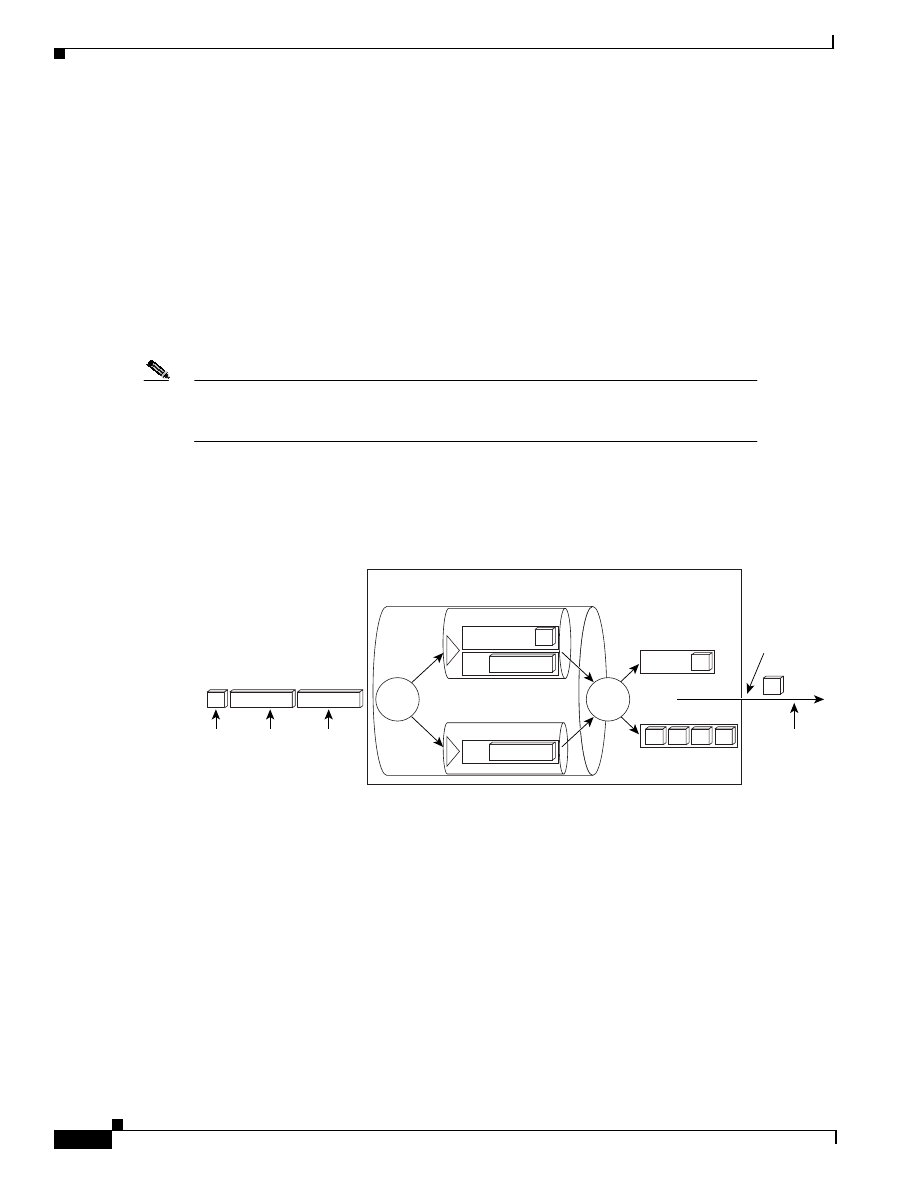
2-28
Quality of Service for Voice over IP Solutions Guide
Version 1.0
Chapter 2
QoS Features for Voice over IP
Link Efficiency Mechanisms
unfragmented VoIP packets into an exhaustive queue ensures their priority delivery over
packets in the low-priority queue. (An exhaustive queue is one whose packets are dequeued
exhaustively, that is, entirely, whenever the queue contains packets and before packets from the
other FIFO queue are serviced.) Use of an exhaustive FIFO queue for voice packets protects
voice flows from heavy traffic sent on PVCs using the same interface. It helps to prevent traffic
sent on other PVCs from detrimentally affecting nonfragmented voice packets in the event that
the other PVCs are oversubscribed or their traffic shaping parameters are misconfigured.
–
The low-priority FIFO queue is used for all other packets, including other small unfragmented
packets.
Figure 2-10 shows FRF.12 enabled on a per-PVC basis for two PVCs: PVC 1 and PVC 2. Notice that
for both PVCs, FRTS is also enabled. WFQ is the only supported queueing mechanism for FRF.12. (All
other queueing types currently supported on a PVC are not allowed.)
Note
When there is no congestion on a PVC, voice traffic is not shaped. Thus, it is not enqueued
to the PQ-WFQ queue. Rather, it is placed in the interface queue of the transmit (TX) ring
or sent directly to the TX ring, depending on whether there is traffic in the TX queue.
Each PVC has its own WFQ structure, which is used to schedule packets appropriately for dequeueing
based on their IP Precedences. Dual-FIFO interface queueing is used at the interface level; these two
FIFO queues are set up automatically when FRTS is configured.
Figure 2-10 A Conceptual View of FRF.12 with Multiple PVCs
Figure 2-11 gives another view of FRF.12 used for three PVCs in which each PVC carries one voice
flow and two data flows. Notice that before the large data frames are fragmented, WFQ is used to
dequeue the frames, or packets, from each set of flows—WFQ gives priority to small packets with low
weight. After they are fragmented, the data frames are sent in order; VoIP packets are interleaved
between the fragments of the jumbogram data frames. The interleaved single flows from each PVC are
sent to the interface queues for enqueueing in the high-priority or low-priority FIFO queues. The Frame
Relay frame is compressed before it is fragmented, and it is decompressed after it is reassembled at the
other end of the link.
1
2
PVC 1
Router queueing structure
Small
VoIP
packet
PVC 1
Frame
Relay
Large
data
packet
PVC 1
Large
data
packet
PVC 2
27094
1
3
2
2
1
1
Priority queue
Fragment
data queue
Exhaustive
queue like
priority
queueing
of interface
queues
3
PVC 2
3
Dequeue
Route
table
2
3
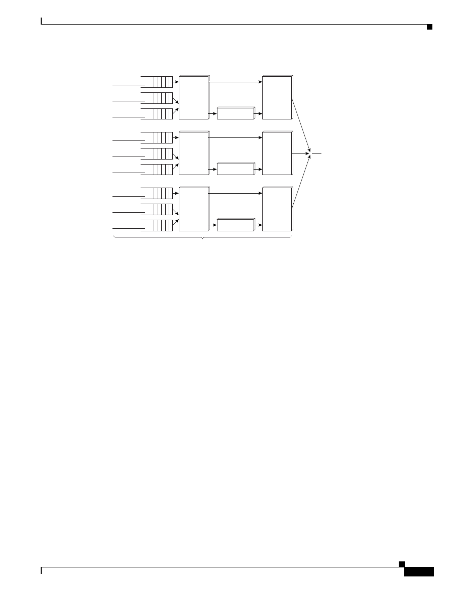
2-29
Quality of Service for Voice over IP Solutions Guide
Version 1.0
Chapter 2
QoS Features for Voice over IP
Link Efficiency Mechanisms
Figure 2-11 PVC Queueing and Fragmentation for FRF.12
MLPPP LFI
MLPPP LFI provides a method of splitting, recombining, and sequencing datagrams across multiple
logical links.
MLPPP LFI is used on slow-speed PPP links to fragment these large data packets and interleave the
resulting fragments with delay-sensitive voice packets in order to provide priority service to voice
traffic. Large packets are fragmented for transmission onto the PPP leased-line trunk, then reassembled
on receipt from the trunk. They do not travel through the entire network as fragments.
To ensure correct order of transmission and reassembly, LFI adds multilink headers to the datagram
fragments after the packets are dequeued and ready to send. Small delay-sensitive packets are not
multilink encapsulated, but are interleaved between fragments of the large datagram. LFI also provides
a special transmit queue for the smaller, delay-sensitive packets, enabling them to be sent earlier than
other flows.
MLPPP allows the fragmented packets to be sent at the same time over multiple point-to-point links to
the same remote address. The multiple links come up in response to a dialer load threshold that you
define. The load can be calculated on inbound traffic, outbound traffic, or on either, as needed for the
traffic between the specific sites. MLPPP provides bandwidth on demand and reduces transmission
latency across WAN links.
MLPPP alone works at the packet level, not at the level of multilink fragments. Thus, without use of
LFI, if a small real-time voice packet gets queued behind a large data packet and no special queue has
been reserved for voice packets, the small voice packet will be scheduled for transmission only after all
the fragments of the larger data packet are scheduled for transmission.
LFI allows reserve queues to be set up so that RTP streams can be mapped into a higher priority queue
in the configured weighted fair queue.
As Figure 2-12 shows, LFI also provides a special transmit queue for the smaller, delay-sensitive
packets, enabling them to be sent earlier than other flows.
Voice flow
Fragmentation
PQ-WFQ
27092
Data flow
PVC A
To the
interface
queues
PVC C
PVC
B
Data flow
Voice flow
Fragmentation
PQ-WFQ
Data flow
Data flow
Voice flow
Fragmentation
Frame Relay traffic shaping
PQ-WFQ
Data flow
Data flow
Interleaving
Interleaving
Interleaving
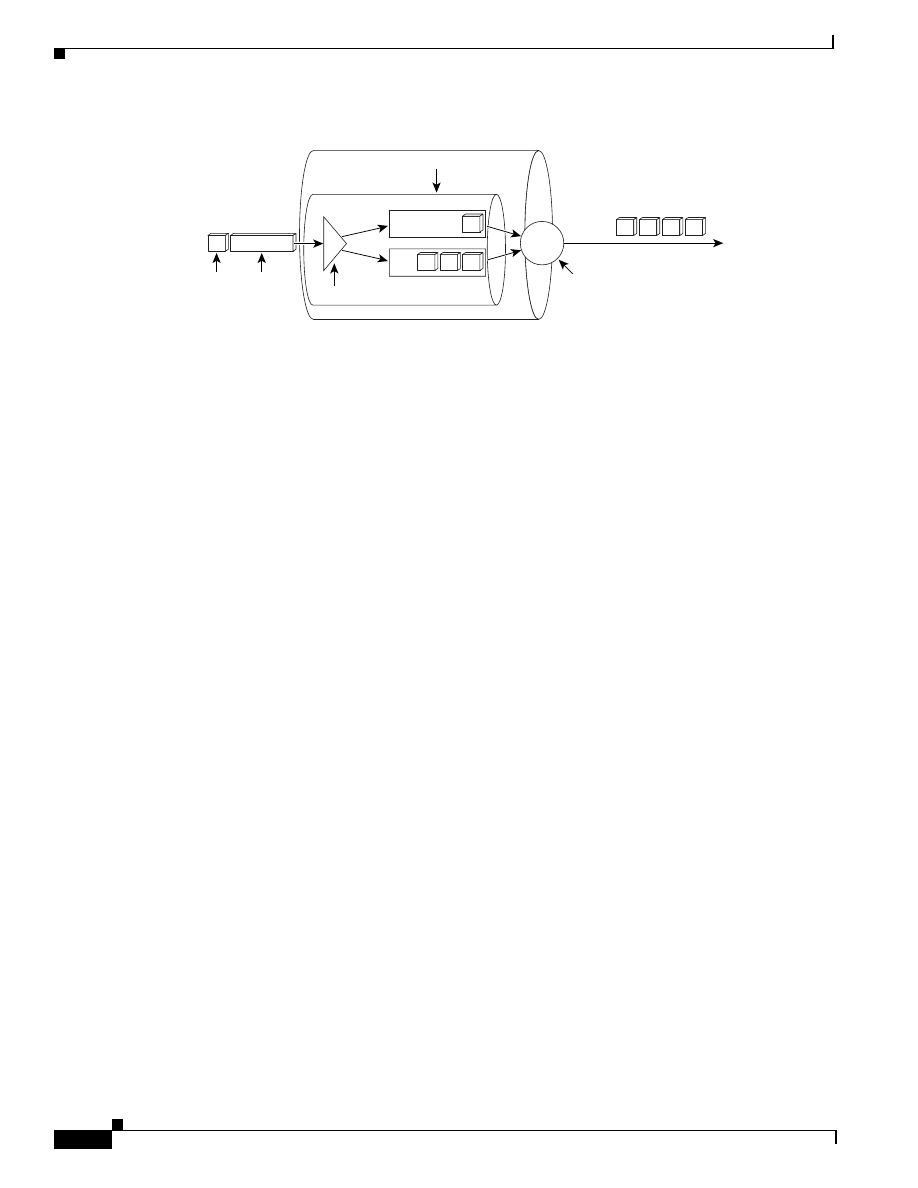
2-30
Quality of Service for Voice over IP Solutions Guide
Version 1.0
Chapter 2
QoS Features for Voice over IP
Link Efficiency Mechanisms
Figure 2-12 MLPPP LFI
IP MTU Size Reduction
The IP MTU Size Reduction feature allows you to reduce the size of IP packets at Layer 3. Using this
feature, you can fragment large packets and interleave them with VoIP packets. The fragments are not
reassembled at the other side of the link, but are sent as fragments until they reach their final destination.
IP MTU size reduction offers a good fragmentation method when you need to send fragmented and
interleaved frames, for instance, from a Frame Relay network across an ATM network and WAN cloud
to a destination Frame Relay link. However, use of IP MTU size reduction is not ideal for the following
reasons, which you should take into account when deciding whether to use it:
•
Large frames belonging to protocols other than IP are not fragmented. If your network is
multiprotocol in its support, large, unfragmented frames could pose a problem. For instance, if
large non-IP frames are sent, their transmission will vary the delay, a situation intolerable to voice,
which requires delay constancy.
•
Small fragments can lead to performance inefficiencies. Reducing the IP MTU size below
300 bytes may adversely affect an application as well as router endpoint performance. For instance,
on a 56-kbps circuit, the MTU size is commonly set to 300 bytes to achieve a minimum blocking
delay of 42 ms.
•
Fragmentation can lead to a condition colloquially known as “packet bloat.” For example, consider
the case of packet bloat that occurs in which a 1500-byte frame is broken into 300-byte fragments,
each fragment now carrying a 40-byte header. The overhead incurred by the necessary headers for
each discrete fragment results in consumption of additional bandwidth. Because the packets travel
the entire course of the internetwork as fragments with headers, this overhead persists for the
transmission duration.
CRTP
RTP, the Internet-standard protocol for the transport of real-time data, provides end-to-end network
transport functions suitable for sending voice traffic over multicast or unicast network services. CRTP
is used in conjunction with RTP to reduce, or compress, the extensive RTP header, resulting in
decreased consumption of available bandwidth for voice traffic manifesting as a corresponding
reduction in delay. You use CRTP on a link-by-link basis. CRTP is currently process switched.
Bandwidth is at a premium on low-speed WAN links, necessitating that you compress any voice traffic
you intend to send over these links. CRTP is required to ensure VoIP scalability which would otherwise
be impossible due to the extensive overhead incurred by the size of VoIP packets, which include the IP
header, the UDP header, and the RTP header, in addition to the voice payload.
Configurable queues
Transmit,
WFQ, or
reserved,
scheduling
Classify
Dequeue
27095
1
2
2
2
Small
packet
Large
packet
1
2
1
2
2
2
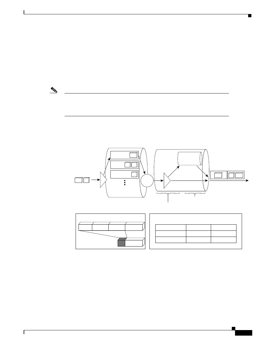
2-31
Quality of Service for Voice over IP Solutions Guide
Version 1.0
Chapter 2
QoS Features for Voice over IP
Link Efficiency Mechanisms
For example, a G.729 (8 K codec) VoIP call expands to 24 kbps when the IP/UDP/RTP headers are
added. Considering that another 5 to 7 bytes of overhead are incurred per packet at Layer 2, a VoIP call
could require up to 26 kbps. CRTP can compress the IP/UDP/RTP headers to as little as 2 bytes,
resulting in a 12-kbps G.729 call.
CRTP is especially beneficial when the RTP payload size is small, as is the case for compressed voice
payloads. The payload of a typical voice packet using RTP is 20 bytes, while the header is often twice
this size—the minimal 12 bytes of the RTP header, combined with 20 bytes of IP header (IPH) and 8
bytes of UDP header, create a 40-byte IP/UDP/RTP header. Given the size of the IP/UDP/RTP header
combinations, it is inefficient to send the IP/UDP/RTP header without compressing it.
Note
The voice payload size is usually configurable in 10-byte increments to a maximum of
240 bytes; the limits are codec-specific. Increasing the payload size reduces the overall
voice channel bandwidth. However, the improvement in bandwidth is gained at the
expense of voice connection delay.
Figure 2-13 shows the point at which CRTP header compression occurs in the transmission of a voice
packet. It also notes the degree of compression for VoIP packets.
Figure 2-13 Compression of Real-Time Protocol Packet Header
A full-rate voice call consumes about 84 kbps of network bandwidth. To avoid unnecessary
consumption of available bandwidth, you should use CRTP on a link-by-link basis to reduce the RTP
header to 2 to 4 bytes. Reducing the bandwidth necessary for each voice call increases the number of
calls that can be sent on a given trunk.
Table 2-8 shows some combinations of codec, payload size, CRTP, and voice activity detection (VAD)
used to compress data. G.729B includes an integral VAD function but otherwise has identical
performance to G.729. The following assumptions are made:
•
The RTP/UDP/IP header is 40 bytes. (CRTP reduces this amount to 2 bytes but MLPPP adds 6
bytes.)
27949
Traffic destined
for interface
Transmit
queue
RTP
compressor
Output
line
Non-RTP
RTP traffic
(video,
audio, and
so on)
Compression
Identify RTP
traffic
RTP
UDP
IPH
IP Data
5
IP Data
VoIP
Efficiencies
*Also 5-ms reduction in serialization delay at 64 kbps
Payload
Packet size
reduction*
20 bytes
~ 240%
SQL
256 bytes
~ 13%
FTP
1500 bytes
~ 2.3%
Classify
12
8
20
Configured
queueing

2-32
Quality of Service for Voice over IP Solutions Guide
Version 1.0
Chapter 2
QoS Features for Voice over IP
Congestion Avoidance
•
FRF.12 adds 6 bytes to the header, including the Frame Relay header and checksum. (Thus, the
values for FRF.12 are the same as those for MLPPP.)
•
VAD is assumed to reduce utilization to 65 percent of the full rate.
You should use CRTP on any slow-speed WAN interface where bandwidth is a concern and there is a
high portion of RTP traffic. However, you should avoid using CRTP on high-speed interfaces—that is,
links whose speed exceeds the T1 speed—because the trade-offs are undesirable.
CRTP is supported on serial lines using Frame Relay, HDLC, or PPP encapsulation. It is also supported
over Integrated Services Digital Network (ISDN) interfaces.
Congestion Avoidance
Congestion avoidance techniques attempt to anticipate and avoid congestion at common network
bottlenecks. Congestion most often occurs on WAN links. Global WAN congestion lends greater cause
for concern than does campus congestion. This section describes the WRED Cisco IOS QoS feature and
its variations. Though not applicable to voice traffic in most cases because it is essentially a packet-drop
mechanism best used in TCP environments, WRED can be used for links sending voice traffic under
certain situations. This section describes those situations.
•
Table 2-9 shows the versions of the Cisco IOS software that support the WRED feature, the
switching mode used, and the platforms WRED runs on.“All Cisco IOS platforms” refers to this set
of platforms: 1000, 1600 series, 1720, 2500 series, 2600 series, 3600 series, 4500 series, 4700
series, 7200 series, and RSP in the 7500.
Table 2-8
Data Compression and Codec, Payload Size, and Use of QoS Features
Compression Technique
Payload Size
Bandwidth at
Full Rate with
MLPPP or
FRF.12
Bandwidth
with CRTP and
MLPPP
Bandwidth
with VAD and
MLPP or FRF.12
Bandwidth with
CRTP, VAD, and
MLPPP or FRF.12
G.711 (64 kbps)
240 bytes
76 kbps
66 kbps
50 kbps
43 kbps
G.711 (64 kbps)
120 bytes
89 kbps
68 kbps
58 kbps
44 kbps
G.726 (32 kbps)
120 bytes
44 kbps
34 kbps
29 kbps
22 kbps
G.726 (32 kbps)
60 bytes
57 kbps
36 kbps
37 kbps
24 kbps
G.726 (24 kbps)
80 bytes
38 kbps
27 kbps
25 kbps
17 kbps
G.726 (24 kbps)
40 bytes
52 kbps
29 kbps
34 kbps
19 kbps
G.728 (16 kbps)
80 bytes
25 kbps
18 kbps
17 kbps
12 kbps
G.728 (16 kbps)
40 bytes
35 kbps
19 kbps
23 kbps
13 kbps
G.729 (8 kbps)
40 bytes
17.2 kbps
9.6 kbps
11.2 kbps
6.3 kbps
G.729 (8 kbps)
20 bytes
26.4 kbps
11.2 kbps
17.2 kbps
7.3 kbps
G.723.1 (6.3 kbps)
48 bytes
12.3 kbps
7.4 kbps
8.0 kbps
4.8 kbps
G.723.1 (6.3 kbps)
24 bytes
18.4 kbps
8.4 kbps
12.0 kbps
5.5 kbps
G.723.1 (5.3 kbps)
40 bytes
11.4 kbps
6.4 kbps
7.4 kbps
4.1 kbps
G.723.1 (5.3 kbps)
20 bytes
17.5 kbps
7.4 kbps
11.4 kbps
4.8 kbps

2-33
Quality of Service for Voice over IP Solutions Guide
Version 1.0
Chapter 2
QoS Features for Voice over IP
Congestion Avoidance
•
The following abbreviations are used to represent various switching modes in this table:
–
P = Process
–
F = Fast
–
N = NetFlow
–
O = Optimum
–
CEF = Cisco Express Forwarding
–
d = distributed (VIP)
–
dCEF = distributed CEF
WRED
The WRED QoS feature combines IP Precedence and standard Random Early Detection (RED)
capabilities to provide differentiated performance characteristics for different classes of service—thus
allowing for preferential handling of voice traffic under congestion conditions without exacerbating the
congestion. WRED is especially useful in high-speed transit networks.
How Does WRED Apply to Voice Traffic?
Although WRED provides good congestion avoidance capabilities designed to increase aggregate
network throughput maximizing capacity utilization while carefully managing packet discard, it does
not give voice traffic the strict priority that it requires. WRED can only provide preferential treatment
for high priority traffic such as voice packets during congestion situations, minimizing voice packet loss
and delay while discarding standard traffic earlier and more aggressively. That understood,
configuration of WRED is directly or indirectly useful for voice traffic under the following conditions:
•
WRED can be used to classify traffic on GSR platforms forming the core of a network. WRED can
also serve as the queueing discipline. WRED uses and interprets IP Precedence to give priority to
voice traffic over data traffic, dropping only data packets.
•
When there are concurrent TCP flows on a link that supports voice traffic, WRED should be used
for the TCP flows, whereas strict priority should be configured for the voice flow, if the feature is
available.
Table 2-9
Cisco IOS Versions, Switching Modes, and Platform Support for Congestion Avoidance Features
Feature
Cisco IOS Version and Switching Mode
Platform Support
10.3
11.0
11.1
11.2
11.1CC
11.3
12.0
Congestion Avoidance
Weighted
Random Early
Detection
(WRED)
—
—
—
P, F, N,
O
—
P, F, N,
O
P, F, N,
O, C
All Cisco IOS platforms: Catalyst
5000 series, Catalyst 6000 series,
12000
Distributed
Weighted
Random Early
Detection
(DWRED)
—
—
—
—
dCEF
—
dCEF
VIP distributed
Flow WRED
—
—
—
—
—
—
P, F, N,
O, C
All Cisco IOS platforms
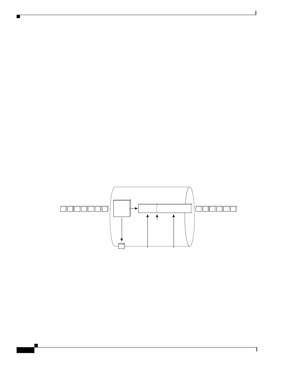
2-34
Quality of Service for Voice over IP Solutions Guide
Version 1.0
Chapter 2
QoS Features for Voice over IP
Congestion Avoidance
Overview
WRED has the following features:
•
It distinguishes between temporary traffic bursts that can be accommodated by the network and
excessive offered load likely to monopolize network resources.
•
It provides fair bandwidth reduction to curtail traffic sources in proportion to the bandwidth being
utilized.
•
It provides you with considerable flexibility including parameters to set minimum and maximum
queue depth thresholds and packet drop probability.
Using WRED, you can define minimum and maximum queue depth thresholds and drop probabilities
for each class of service. You can use WRED to benefit VoIP traffic by specifying that WRED should
not drop voice packets when the queue depth is exceeded, if voice packet drop is avoidable.
However, implicit in WRED are certain limitations in regard to voice traffic that you should understand
if you plan to use it. For instance:
•
WRED used alone does not give bandwidth guarantees to voice.
•
WRED works best in conjunction with robust transport protocols such as TCP that react to packet
drop. VoIP relies on UDP, which does not react to packet drop. In other words, WRED does not
strictly protect against flows such as UDP that do not react to packet drop. Consequently, an
extremely heavy UDP flow could overflow a WRED queue, resulting in loss of voice packets.
Figure 2-14 illustrates how WRED activity is carried out to determine which packets are enqueued and
then dropped or sent during periods of congestion affecting the queue depth threshold.
Figure 2-14 Weighted Random Early Detection
When WRED is not configured, router and switch behavior allows output buffers to fill during periods
of congestion. By default, tail drop is used to address the buffer congestion.
If a link is oversubscribed, a potentially large number of packets from numerous connections are
discarded, leading to a condition called global synchronization. WRED handles this situation
proactively. That is, when WRED is configured, instead of waiting for buffers to fill and tail drop to go
into effect, WRED anticipates congestion by intelligent queue occupancy monitoring. It checks the
buffer depth and performs early discards on selected packets and selected connections. Early discard
improves the overall utilization of the link because it allows connections to slow down gradually.
FIFO scheduling
Queue depth
Output line
Fail
Pass
Drop at
WRED
rate
WRED
threshold
Pass
all
27096
2
1
2
1
2
1
1
2
2
2
2
1
2
2
Discard
Test

2-35
Quality of Service for Voice over IP Solutions Guide
Version 1.0
Chapter 2
QoS Features for Voice over IP
Traffic Shaping and Policing
WRED adds to its congestion avoidance features the ability to apply different discarding algorithms
depending on the precedence. Thus, WRED can begin to discard traffic of precedence 0 (best effort) at
a relatively low buffer occupancy, while it will discard traffic from precedence 1 only at a much higher
buffer occupancy. Thus best-effort traffic will be slowed down much sooner than guaranteed traffic such
as voice.
You can configure WRED on a per-PVC level so that it runs on each PVC queue to ensure low loss for
high-precedence voice traffic on that queue.
Traffic Shaping and Policing
Traffic shaping provides the ability to limit the transmit rate of traffic out an interface to a specific
peak/average value—a rate that is less than the link speed and therefore well tolerated. Policing, such
as is enacted by the rate limiting feature of CAR, allows you to allocate bandwidth for traffic sources
and specify policies for traffic that exceeds the configured bandwidth amount. Policing with CAR and
shaping with FRTS both use the token bucket mechanism.
Traffic shaping is only applicable to Frame Relay or ATM networks. If the media is a leased line, FRTS
does not apply. Use of FRTS is essential for Frame Relay to address a number of conditions, such as
link (circuit) speed mismatch and oversubscription, both of which are described in this section. FRTS
is also essential in cases for which you want to prohibit bursting above the committed information rate
(CIR). Moreover, FRTS is required to support FRF.12.
•
For each congestion avoidance feature, Table 2-10 shows the versions of the Cisco IOS software
that support the feature, the switching mode used, and the platforms the feature runs on. “All Cisco
IOS platforms” refers to this set of platforms: 1000, 1600 series, 1720, 2500 series, 2600 series,
3600 series, 4500 series, 4700 series, 7200 series, and RSP in the 7500.
•
The following abbreviations are used to represent various switching modes in this table:
–
P = Process
–
F = Fast
–
N = NetFlow
–
O = Optimum
–
CEF = Cisco Express Forwarding
–
d = distributed (VIP)
–
dCEF = distributed CEF

2-36
Quality of Service for Voice over IP Solutions Guide
Version 1.0
Chapter 2
QoS Features for Voice over IP
Traffic Shaping and Policing
Token Bucket Mechanism
A token bucket is used to manage a device that regulates the flow of data. For example, the regulator
might be a traffic policer, such as CAR, or a traffic shaper, such as FRTS. A token bucket itself has no
discard or priority policy. Rather, a token bucket discards tokens and leaves to the flow the problem of
managing its transmission queue if the flow overdrives the regulator. (Neither CAR nor FRTS
implement either a true token bucket or a true leaky bucket.)
A token bucket is a formal definition of a rate of transfer. It has three components: a burst size, a mean
rate, and a time interval (Tc). Although the mean rate is generally represented as bits per second, any
two values may be derived from the third by the relation shown as follows:
mean rate = (burst size)/(time interval)
Here are some definitions of these terms:
•
Mean rate—Also called the CIR, it specifies how much data can be sent or forwarded per unit time
on average.
•
Burst size—Also called the Committed Burst (Bc) size, it specifies in bits per burst how much can
be sent within a given unit of time to not create scheduling concerns.
•
Time interval—Also called the measurement interval, it specifies the time quantum in seconds per
burst.
By definition, over any integral multiple of the interval, the bit rate of the interface will not exceed the
mean rate. The bit rate, may, however, be arbitrarily fast within the interval.
In the token bucket metaphor, tokens are put into the bucket at a certain rate. The bucket itself has a
specified capacity. If the bucket fills to capacity, newly arriving tokens are discarded. Each token is
granted permission for the source to send a certain number of bits into the network. To send a packet,
the regulator must remove from the bucket a number of tokens equal in representation to the packet size.
If not enough tokens are in the bucket to send a packet, the packet either waits until the bucket has
enough tokens or the packet is discarded. If the bucket is already full of tokens, incoming tokens
overflow and are not available to future packets. Thus, at any time, the largest burst a source can send
into the network is roughly proportional to the size of the bucket.
Table 2-10 Cisco IOS Versions, Switching Modes, and Platform Support for Traffic Shaping and Policing Features
Feature
Cisco IOS Version and Switching Mode
Platform Support
10.3
11.0
11.1
11.2
11.1CC
11.3
12.0
Traffic Shaping and Policing
Frame Relay
Traffic Shaping
(FRTS)
—
—
—
P, F,
11.2(9)
—
P, F
P, F, C
All Cisco IOS platforms
Committed
Access Rate
(CAR)
—
—
—
—
—
—
C
Cisco IOS 12.0:
2600 series, 3600 series,
4500 series, 4700 series,
7200 series
Cisco IOS 12.0(4)T:
1600 series, 1720, 2500 series
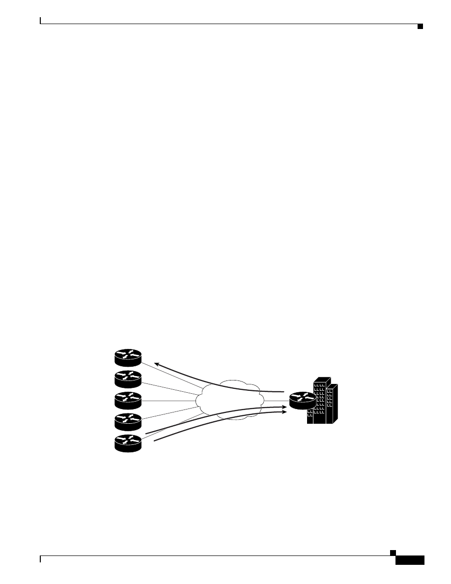
2-37
Quality of Service for Voice over IP Solutions Guide
Version 1.0
Chapter 2
QoS Features for Voice over IP
Traffic Shaping and Policing
Note that the token bucket used for traffic shaping has both a token bucket and a data buffer, or queue;
if it did not have a data buffer, it would be a policer. For traffic shaping, packets that arrive that cannot
be sent immediately are delayed in the data buffer.
For traffic shaping, a token bucket permits burstiness but bounds it. It guarantees that the burstiness is
bounded so that the flow will never send faster than the capacity of the token bucket plus the time
interval divided by the established rate at which tokens are placed in the bucket. It also guarantees that
the long-term transmission rate will not exceed the established rate at which tokens are placed in the
bucket.
FRTS
FRTS uses queueing on a Frame Relay network to limit surges that can cause congestion. FRTS for
voice traffic uses WFQ as an internal queue. FRTS allows you to control the traffic going out an
interface in order to match its flow to the speed of the remote, target interface and to ensure that the
traffic conforms to policies contracted for it. Using FRTS, you can ensure that traffic adhering to a
particular profile can be shaped to meet downstream requirements, thereby eliminating bottlenecks in
topologies with data-rate mismatches.
FRTS lets you specify an average bandwidth size for Frame Relay VCs. You can also define the
bandwidth allocated for bursty traffic and control whether the circuit responds to notifications from the
network that the circuit is becoming congested. Using FRTS, you can define minimum rate commitment
for the virtual circuit and accommodate the occasional need for greater bandwidth.
As Figure 2-15 shows, Frame Relay allows many remote sites to aggregate upon a single circuit through
use of VCs. Data networking is bursty in nature and Frame Relay takes advantage of oversubscription
in relation to this burstiness. Not every remote site may be sending data toward the central site at the
same time. However, the aggregate of all the remote site circuit speeds or PVC speeds may be greater
than the central site circuit speed.
Figure 2-15 Frame Relay Links from Remote Sites Aggregating upon a Single Circuit at a Central Site
Overview
Packet loss can result in detrimental consequences for real-time and interactive applications such as
voice applications. Using FRTS to shape traffic prevents packet loss. Use of FRTS is especially
important in Frame Relay networks because the switch cannot determine which packets take
precedence, and therefore which packets should be dropped when congestion occurs. Moreover,
real-time traffic such as voice traffic requires that latency be bounded, thereby bounding the amount of
128 kbps
256 kbps
512 kbps
Frame Relay, ATM
Remote sites
768 kbps
T1
T1
27098
Central site

2-38
Quality of Service for Voice over IP Solutions Guide
Version 1.0
Chapter 2
QoS Features for Voice over IP
Traffic Shaping and Policing
traffic and traffic loss in the data-link network at any given time by keeping the data in the router that
is making the guarantees. Retaining the data in the router allows the router to prioritize traffic according
to the guarantees it is making.
Consider a Frame Relay network topology that consists of a high-speed (T1 line speed) connection at
the central site and low-speed (less than 56 kbps) connections at the branch sites. This kind of topology
involves a speed mismatch that often produces a bottleneck for traffic on a VC when the faster central
site connection tries to communicate with the slower branch site connection. A bottleneck such as this
introduces poor response times for interactive traffic such as voice traffic, especially when voice packets
must wait behind a large FTP packet on a low-speed line.
FRTS can eliminate bottlenecks in Frame Relay networks that have high-speed connections at the
central site and low-speed connections at branch sites. To limit the rate at which data is sent on the VC
at the central site, you can configure rate enforcement (a peak rate configured to limit outbound traffic)
on a per-VC basis to either the CIR or some other defined value such as the excess information rate
(EIR). Rate enforcement can also be used in conjunction with the existing DLCI prioritization feature
to further improve performance in this situation.
When a Frame Relay network is constructed with many VCs to different locations on a single physical
line into the network, these VCs send traffic as fast as the physical line speed allows. The rate
enforcement capability enables you to control the transmission speed used by the router by other criteria
such as CIR or EIR, providing a mechanism for sharing media by multiple VCs. FRTS can preallocate
the bandwidth each VC receives on the physical line into the network. This effectively creates a virtual
time-division multiplexing (TDM) network.
A shaper, such as FRTS, typically delays excess traffic using a buffer, or queueing mechanism, to hold
packets and shape the flow when the data rate of the source is higher than expected.
Advanced Concepts: Link Speed Mismatches
Link speed (circuit) mismatches can occur between high-speed links to low-speed links when data is
sent from a fast central site link to a slower remote site link or when a central site is oversubscribed by
remote sites. This section discusses the first case and how traffic shaping can reduce ensuing problems.
The “Advanced Concepts: Traffic Shaping and Oversubscription” section discusses the second case.
For data-only networks that rely on TCP, TCP slow-starts allow a TCP flow between two endpoints to
increase its effective flow rate gradually in order to determine the minimum bandwidth link between the
two endpoints. This process negates the need for traffic shaping in data-only networks. This is not the
case for voice transmission that relies on UDP networks.
Traffic sent out an interface may be shaped in such a way that the transmission rate may be different
depending on the destination. This capability is necessary to address the differing remote site link
speeds for circumstances, for instance, in which a central site router must shape traffic destined for one
remote site at a rate of 56 kbps and shape traffic destined for another remote site at 128 kbps.
Consider, for example, that traffic leaving a high-speed interface such as a T1 line at a central site often
terminates at a remote site that may have a circuit speed of, say, 56 kbps. By default, a router will
transmit on an outgoing interface at a data rate that is equal to the clock rate of the circuit itself. This
means that a T1 interface on a router will send data out at a T1 rate even if the remote site has a clock
rate of 56 kbps. (This situation is analogous to four lanes on a highway merging into two lanes.)
Congestion prevails, resulting from the slowdown of high-speed to slow-speed links. A consequence of
this kind of congestion is that packets are queued in buffers, which manifests as delay. Buffers are finite
storage entities that fill up to capacity and overflow, resulting in packet loss. Buffering works well for
data frames, but the delay it incurs is detrimental to voice. Applying traffic shaping to a condition such
as this one enables the queues to handle the T1 transmission, narrowing it down to fit the 56-kbps
limitations without frame buildup in the queues, and thus eliminating delays or drops.

2-39
Quality of Service for Voice over IP Solutions Guide
Version 1.0
Chapter 2
QoS Features for Voice over IP
Traffic Shaping and Policing
Consider another similar case that involves an FTP file transfer. Suppose a voice flow exists between
two IP phones, one at a T1 site and one at a 56-kbps site while the FTP-based file is being transferred.
The file transfer is started and congestion occurs in the Frame Relay network; the congestion causes
buffering of voice packets in the transmission from the T1 line to the 56-kbps line. Even if voice traffic
is given priority above the data traffic at the T1 router, buffering delay occurs in the Frame Relay
network, and both data and voice are affected equally. Both flows are affected because the Frame Relay
network operates at Layer 2, and therefore it has no regard for or knowledge of which frames are voice
frames. Poor voice quality results under these circumstances as a consequence of dropped packets or
delays. The severity of voice degradation incurred depends on the amount of congestion and buffering
that exists in the Frame Relay network.
This possibility of WAN congestion due to link, or circuit, speed mismatches (high speed to low speed)
makes evident the need for the edge router to shape the traffic before it enters the network, which will
help to avoid congestion in the Frame Relay network. In this example—a T1 line to a 56-kbps line—you
would shape the traffic to a rate lower than 56 kbps so that the rate would equal the CIR.
Advanced Concepts: Traffic Shaping and Oversubscription
A remote-to-central site configuration is deemed to be oversubscribed any time the aggregate transmit
ability of the remote site exceeds the link bandwidth of the central site. Any oversubscribed situation is
at risk of having voice negatively impacted depending on network conditions. Oversubscription is a
commonly used design characteristic on data-only environments in which often many remote sites feed
a central site. In this situation, the aggregate link speeds or CIRs of all the remote sites can exceed the
link speed of the central site. Even if the CIRs of all the remote sites collectively are less than the central
site link speed, oversubscription can occur when bursting of all the remote sites exceeds the central site
link speed.
If you run voice traffic over a network design that allows for oversubscribed configuration, you must
use traffic shaping to avoid the degradation to voice quality that can occur when the amount of traffic
from the remote site exceeds the central site’s circuit speed buffering. For instance, if the burst period
during which the remote site transmits data to the central site is extensive, packet drop could occur.
Because it is beneficial to data traffic, oversubscription is a common Frame Relay design
implementation, and therefore it is impossible to eliminate it to properly facilitate voice. You should
understand the risks to voice traffic involved in use of oversubscription and consider how to compensate
for them.
If you want to allow data to be oversubscribed and concurrently guarantee voice quality, Cisco
recommends that you configure the voice bandwidth to be the same as the minimum CIR (mincir) so
that during congestion—that is, when bursting occurs—voice traffic will not be delayed or dropped.
Advanced Concepts: Bursting
On Frame Relay networks, the CIR specifies the guaranteed amount of information carried during
periods of congestion. Bursting over the CIR—a beneficial, common, and intentional practice in a
data-only Frame Relay network—creates a situation in which voice packets are sent out into the Frame
Relay network essentially in a best-effort manner, subjecting them to packet drop.
Typical Frame Relay circuits have a link speed and an associated CIR that is in most cases less than the
line rate. Many network providers allow applications to burst above the guaranteed CIR all the way up
to the line rate. It is well understood that in the event of congestion, bursting about the CIR incurs the
risk of packet loss because any data sent over the CIR is considered best-effort traffic.

2-40
Quality of Service for Voice over IP Solutions Guide
Version 1.0
Chapter 2
QoS Features for Voice over IP
Traffic Shaping and Policing
If you run voice traffic across a network designed to support bursting, it is likely that voice will be
included in the excess bandwidth above the CIR because Frame Relay has no way of differentiating
between voice traffic and data traffic. If global congestion ensues, delay (caused by buffering) and
packet drop could occur. Within a Frame Relay network, if frames must be dropped, those with the
discard eligible (DE) bit set will be dropped first.
It is imperative to accept the premise that for a Frame Relay network to carry voice along with data, you
must relinquish some of the benefits that bursting can give to data traffic because it is so detrimental to
voice. Most importantly, to curtail the risks implicit in bursting, you should use traffic shaping on each
PVC to ensure that the outbound traffic rate of traffic leaving the router going into the Frame Relay
network does not exceed the CIR. Although this condition could reduce throughput of other data, it
guarantees throughput and constant delay to voice traffic even when congestion occurs.
That said, there are a number of ways you can configure the Frame Relay network to handle traffic that
bursts above the CIR when congestion occurs:
•
You can drop frames that are sent above the CIR.
•
You can drop frames with the DE set.
•
You can mark frames above the CIR as DE and buffer (delay) them, but still send them.
Deploying QoS traffic regulation mechanisms such as policing and shaping throughout a network
ensures that the correct QoS is rendered to a packet and that the data source adheres to the stipulated
contract.
CAR
CAR provides a rate-limiting feature that allows you to allocate both bandwidth commitments and
bandwidth limitations to traffic sources and destinations while specifying policies for handling traffic
that exceeds the bandwidth allocation.
How Does CAR Apply to Voice Traffic?
Despite the advent of strict priority queueing for voice traffic, there remain some circumstances in
which either the ability of CAR to police traffic through rate limiting or its IP Precedence
traffic-marking ability is still useful for voice traffic. For instance, here are cases when you should use
CAR for voice traffic:
•
Rate limiting
If the queueing and scheduling discipline applied to the link is First-In First-Out (FIFO), you
should configure CAR to rate limit traffic. To give priority to voice traffic, you should rate limit
data traffic, but not voice traffic. In order to police traffic advantageously for voice traffic, CAR
must be able to differentiate between voice traffic and other forms of traffic. Therefore, you must
mark the traffic with IP Precedence.
•
Traffic marking
In later releases of Cisco (IOS 12.0(5)T and beyond) that support use of a strict priority queue
within WFQ, you no longer need to mark traffic with IP Precedence to satisfy voice traffic
requirements. If you configure strict priority, voice traffic is enqueued in the priority queue and
scheduled for transmission before any other traffic. However, use of strict priority for voice traffic
is limited to Cisco IOS platforms. Moreover, there is no persistence at the packet level that indicates
the packet is entitled to strict priority treatment; when strict priority is used, the packet is not
marked with priority as it is when IP Precedence is used to set priority.
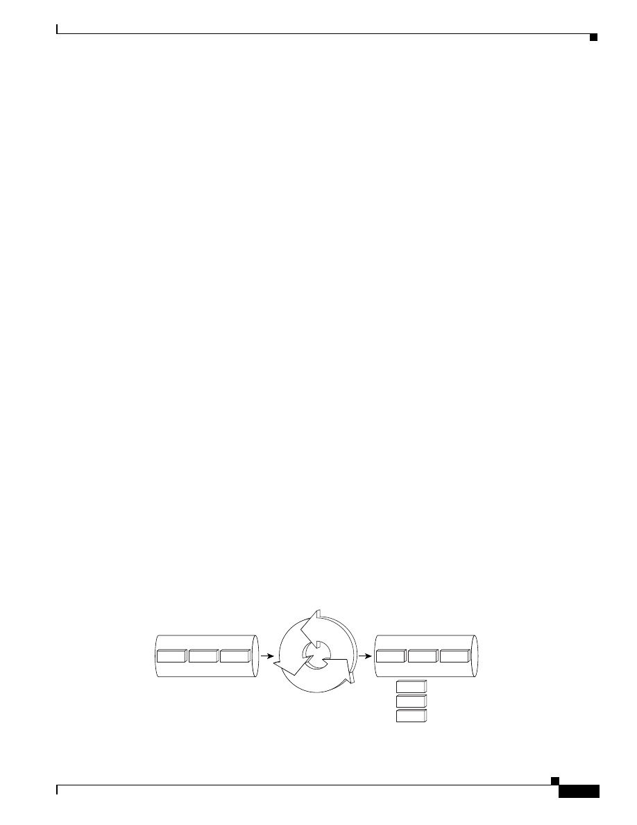
2-41
Quality of Service for Voice over IP Solutions Guide
Version 1.0
Chapter 2
QoS Features for Voice over IP
Traffic Shaping and Policing
Therefore, although strict priority meets the queueing and scheduling requirements of voice traffic,
largely replacing the need for WFQ and traffic marking, it is still important that you mark voice
packets with an IP Precedence of 5 if that traffic will be sent across an internetwork. This
requirement exists because platforms such as GSR routers, which are heavily used to form the core
(or backbone) of networks such as ISP networks, do not support strict priority.
In some cases, WRED is used as the scheduling mechanism on GSR platforms, and WRED relies
on IP Precedence to determine which packets to drop. Even traffic assigned to a priority voice class
within CBWFQ should be marked with IP Precedence so that voice traffic can be differentiated
from data traffic in the core of another network. You can use CAR to mark packets at the edge of
the network.
Overview
CAR is used to enforce a maximum transmit rate (rate limit) for IP traffic only. Non-IP traffic is not rate
limited. As a traffic policer, the rate limiting feature of CAR is most commonly configured on interfaces
at the edge of a network to limit traffic into or out of the network. CAR does not smooth or shape traffic
and thus does no buffering and adds no delay. CAR is highly optimized to run on high-speed links in
distributed mode on VIPs on the Cisco 7500 series.
The CAR rate-limiting feature uses token bucket filters to measure the traffic load and limit sources to
bandwidth allocations while accommodating the inherently bursty nature of IP traffic. For traffic that
exceeds allocated bandwidth, CAR utilizes Extended ACLs to define policies, including bandwidth
utilization thresholds under which packet priority is modified or packets are dropped.
Using the rate limiting functionality of CAR, you can do the following:
•
Define Layer 3 aggregate (matching all of the packets on an interface or subinterface) or granular
(matching a particular type of traffic based on precedence, MAC address, or other parameters)
access or egress bandwidth rate limits.
•
Specify traffic handling policies when the traffic either conforms to or exceeds the specified rate
limits.
•
Control the maximum rate of traffic sent or received on an interface.
You can specify CAR rate-limiting policies based on criteria including physical port, packet
classification, IP address, MAC address, application flow, or other criteria specifiable by access lists or
extended access lists. You can implement CAR rate limits in either input or output interfaces or
subinterfaces that support dCEF including Frame Relay and ATM subinterfaces.
Figure 2-16 conceptualizes the CAR rate-limiting process.
Figure 2-16 Committed Access Rate
1st class
2st class
3st class
Ingress 155 mbps pipe
Rate limited to 100 mbps
CAR Engine
Separate, conform,
and exceed actions
27097
FTP
HTTP
VoIP
VoIP
HTTP
FTP

2-42
Quality of Service for Voice over IP Solutions Guide
Version 1.0
Chapter 2
QoS Features for Voice over IP
Traffic Shaping and Policing
Note
dCEF switching must be enabled on any interface that uses VIP-Distributed CAR, even
when only output CAR is configured. For dCEF configuration information, see the Cisco
IOS Switching Services Configuration Guide. A VIP2-50 interface processor is strongly
recommended when the aggregate line rate of the port adapters on the VIP is greater than
DS3. A VIP2-50 interface processor is required for OC-3 rate PAs.
Advanced Concepts
CAR measures Layer 3 bandwidth utilization using a token bucket filter. Because CAR uses a token
bucket, it can pass temporary bursts that exceed the rate limit as long as tokens are available. Thus, the
token bucket can accommodate the bursty nature of IP traffic while still enforcing a specified rate limit.
Once a packet has been classified as conforming to or exceeding a particular rate limit, the router
performs one of the following actions on the packet:
•
Transmit—The packet is sent.
•
Drop—The packet is discarded.
•
Set precedence and transmit—The IP Precedence (ToS) bits in the packet header are rewritten. The
packet is then sent.
•
Continue—The packet is evaluated using the next rate policy in a chain of rate limits. If there is not
another rate policy, the packet is sent.
CAR does not smooth or shape traffic and thus does no buffering and adds no delay.
You can also use CAR to specify more complex bandwidth management policies; to do so you can
cascade or chain together a series of rate limits for specifying granular traffic control policies—the
sequence of rate limits is evaluated and conform or exceed actions are executed until a packet is either
sent or discarded. Packets falling through to the bottom of the list of rate limits are sent. Use of cascaded
rate limits gives you very fine-grained network resource control.
Rate-limiting application examples include the following:
•
Application-based rate limits: For example, limit HTTP web traffic to 50 percent of the link
bandwidth, thus ensuring capacity for voice applications.
•
Subrate IP services. For example, the network delivers a physical T1/E1 or T3/E3 to the customer
but offers a less expensive subrate service, that is, 1 Mbps on an E1 or 10 Mbps on a T3. The
customer only pays for the subrate bandwidth and may be upgraded to additional access bandwidth
over time based on demand. CAR limits the traffic rate available to the customer and delivered to
the network to the agreed upon rate limit and limits the ability to temporarily burst over the limit.
The network operator may upgrade the service without any physical network rearrangement.
•
Web hosting service. For example, a service provider hosts a web server farm providing outsourced
services for multiple customers. Customers payment levels are set based on both bandwidth
capacity and traffic prioritization. Customers may sign up for maximum delivered bandwidth of 2
Mbps and medium traffic prioritization. The service provider uses CAR functionality to limit the
web server of the customer as the medium for appropriate traffic handling under congestion.

2-43
Quality of Service for Voice over IP Solutions Guide
Version 1.0
Chapter 2
QoS Features for Voice over IP
Classification
Classification
Packet classification enables network managers to specify policies that identify network traffic in order
to partition, or classify, that traffic into multiple priority levels or CoS. Cisco IOS QoS for VoIP features
include these technologies that you can use to classify packets:
•
BGP Policy Propagation to set IP Precedence. Cisco IP Phones are a family of full-featured phones
that can be plugged directly into the LAN. They include two models: 30VIP and 12SP+.
•
Dial Peers, which can be used to set IP Precedence for voice packets.
•
BGP Policy to set IP Precedence of QoS group ID
After classification, routers at the network edge ensure that packets within a class receive appropriate
service levels, such as allocated rates and loss probability.
Table 2-11 shows the Cisco IOS software versions that support BGP Policy Propagation, the switching
mode used, and the platforms it runs on.
Terms used in Table 2-11 are explained as follows:
•
“All Cisco IOS platforms” refers to this set of platforms: 1000, 1600 series, 1720, 2500 series, 2600
series, 3600 series, 4500 series, 4700 series, 7200 series, and RSP in the 7500.
•
“VIP distributed” refers to this set of platforms: 7000, 7500, and the Router Switch Module (RSM).
•
The following abbreviations are used to represent various switching modes in this table:
–
P = Process
–
F = Fast
–
N = NetFlow
–
O = Optimum
–
CEF = Cisco Express Forwarding
–
d = distributed (VIP)
–
dCEF = distributed CEF
BGP Policy Propagation
BGP is an interdomain routing protocol that exchanges reachability information with other BGP
systems. The QoS policy propagation via Border Gateway Protocol (BGP) feature allows you to classify
packets and then use other QoS features such as CAR and WRED to specify and enforce business
policies to fit your business model.
Table 2-11
Cisco IOS Versions, Switching Modes, and Platform Support for Classification Features
Feature
Cisco IOS Version and Switching Mode
Platform Support
10.3
11.0
11.1
11.2
11.1CC
11.3
12.0
Classification
BGP Policy
Propagation
—
—
—
—
dCEF,
CEF
—
—
7500 VIP or RSP, 7200

2-44
Quality of Service for Voice over IP Solutions Guide
Version 1.0
Chapter 2
QoS Features for Voice over IP
IP to ATM CoS
Overview
BGP policy propagation leverages BGP to distribute QoS policy to remote routers in your network. It
allows ingress routers to prioritize traffic. BGP policy propagation is defined by RFC 1163.
You can filter routing updates by specifying an access list on both incoming and outbound updates based
on the BGP autonomous system path in the following ways:
•
By setting IP Precedence for a packet.
•
By tagging the packet with a QoS class unidentified (QoS group ID) internal to the router.
•
A QoS group ID is a user-specified number that is assigned to a packet when that packet matches
user-specified criteria. You set an internal QoS group ID, classify the packet with the number, then
use that number to perform rate-limiting based on QoS group ID.
•
Through source and destination address lookup.
You can specify whether the IP Precedence level or QoS group ID used is obtained from the source
(input) address or destination (output) address entry in the route table. By setting the QoS group ID in
addition to the IP Precedence, you can have more than eight classes on which to perform rate limiting.
For the QoS Policy Propagation via BGP feature to work, you must enable BGP and CEF/dCEF on the
router. Subinterfaces on an ATM interface that have the bgp-policy command enabled must use CEF
mode because distributed CEF is not supported. (Note that dCEF uses the VIP rather than the RSP to
perform forwarding functions.)
IP to ATM CoS
Cisco IOS QoS software includes a feature suite that maps QoS characteristics between IP and ATM.
Two phases of this feature suite, characterized as follows, are highly useful for VoIP traffic:
•
Phase 2, which encompasses two main parts:
–
IP to ATM CoS support for a single ATM VC, which allows you to use existing features, such as
CAR or policy-based routing, to classify and mark different IP traffic by modifying the IP
Precedence field in the IPv4 packet header. Subsequently, WRED or Distributed WRED can be
configured on a per-VC basis so that the IP traffic is subject to different drop probabilities (and
therefore priorities) as IP traffic coming into a router competes for bandwidth on a particular VC.
–
ATM VC bundle management allows you to configure multiple VCs that have different QoS
characteristics between any pair of ATM-connected routers. These VCs are grouped in a bundle
and are referred to as bundle members.
•
Phase 3 IP to ATM CoS, per-VC WFQ, and CBWFQ allows you to apply CBWFQ
functionality—normally applicable at the interface or subinterface levels only—to an individual VC
configured for IP to ATM CoS. You can use this extension to IP to ATM CoS to apply either CBWFQ
class-based WFQ or flow-based WFQ on a per-VC basis.
This section describes both of these IP to ATM CoS features. For each feature, Table 2-12 shows the
versions of the Cisco IOS software that support the feature, the switching mode used, and the platforms
it runs on.
•
The following abbreviations are used to represent various switching modes in this table:
–
P = Process
–
F = Fast
–
CEF = Cisco Express Forwarding

2-45
Quality of Service for Voice over IP Solutions Guide
Version 1.0
Chapter 2
QoS Features for Voice over IP
IP to ATM CoS
IP to ATM, per-VC WFQ, and VC Bundling (Phase 2)
The IP to ATM Class of Service (IP to ATM CoS) feature implements a solution for coarse-grained
mapping of QoS characteristics between IP and ATM, using Cisco PA-A3 ATM port adapters on Cisco
7200 and 7500 series routers. (This category of coarse-grained QoS is often referred to as CoS). The
resulting feature makes it possible to support differential services in network service provider
environments.
IP to ATM CoS provides a true working solution to class-based services, without the investment of new
ATM network infrastructures. Using this feature, you can do the following:
•
Offer different service classes (sometimes termed “differential service classes”) across the entire
WAN, not just the routed portion.
•
Give mission-critical applications exceptional service during periods of high network usage and
congestion. In addition, noncritical traffic can be restricted in its network usage, which ensures
greater QoS for more important traffic and user types.
IP to ATM CoS supports configuration of both a single ATM VC and VC bundles. It does the following:
•
Ensures effective differential classes over IP and traditional ATM networks. For instance, the VC
bundle management feature provides for differentiated QoS by allowing for the coexistence of
multiple VCs with different QoS characteristics from the same source to the same destination.
•
Uses existing ATM infrastructures.
•
Implements solutions for coarse-grained mapping of QoS characteristics called CoS between IP
and ATM.
•
Employs a high-performance design benefiting from distributed processing on the Cisco 7500
series routers and VIP.
•
Uses the Cisco advanced PA-A3 ATM port adapter (PA), which supports traffic shaping and has
rich ATM Service Category support. This PA is supported on the Cisco 7500+VIP and 7200 series
routers.
•
Provides per-VC queueing on the PA, per-VC back pressure, and per-VC WRED VIP queueing,
which bring stability to a network by ensuring that system packets—such as BGP and Intermediate
System-to-Intermediate System (ISIS)—are never dropped.
•
Provides flexible management of the VC bundle on PVC failure.
Table 2-12 Cisco IOS Versions, Switching Mode, and Platform Support for IP to ATM CoS Features
Feature
Cisco IOS Version and Switching Mode
Platform Support
10.3
11.0
11.1
11.2
11.1CC
11.3
12.0
IP to ATM Class of Service
VC Bundling
(Phase II)
—
—
—
—
—
—
P, F, C
12.0(3)T: 7200 and 7500
Per-PVC PQ
within CBWFQ
—
—
—
—
—
—
—
12.0(7)T: 7200
12.0(7)XE: 7500
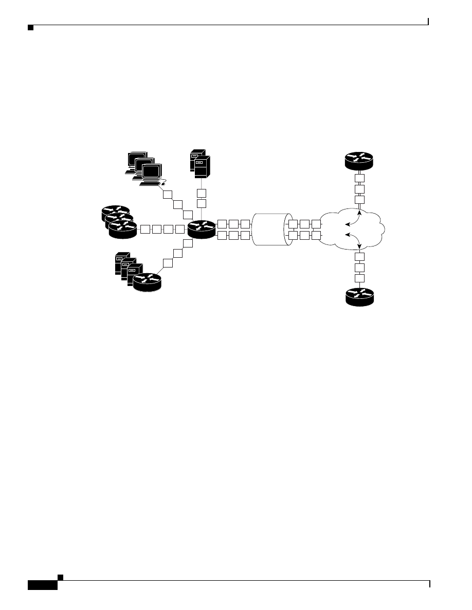
2-46
Quality of Service for Voice over IP Solutions Guide
Version 1.0
Chapter 2
QoS Features for Voice over IP
IP to ATM CoS
IP to ATM CoS support for a single ATM VC allows you to use existing features, such as CAR or
policy-based routing to classify and mark different IP traffic by modifying the IP Precedence field in
the IPv4 packet header (PBR). Subsequently, WRED or Distributed WRED can be configured on a
per-VC basis so that the IP traffic is subject to different drop probabilities (and therefore priorities) as
IP traffic coming into a router competes for bandwidth on a particular VC.
Figure 2-17 shows two PVCs carrying traffic whose QoS is mapped to ATM VCs with equivalent QoS.
Figure 2-17 IP to ATM CoS Support for Single ATM VCs
PA-A3 ATM port adapters provide the ability to shape traffic on each VC according to the ATM service
category and traffic parameters employed. When you use the IP to ATM CoS feature, congestion is
managed entirely at the IP layer by WRED running on the routers at the edge of the ATM network.
IP to ATM CoS VC bundle management allows you to configure multiple VCs that have different QoS
characteristics between any pair of ATM-connected routers. These VCs are grouped in a bundle and are
referred to as bundle members. Figure 2-18 shows four PVCs whose traffic is mapped to ATM VCs with
equivalent QoS characteristics.
27100
2
1
1
2
1
2
2
2
1
PVC 1
PVC 2
2
1
1
1
1
1
1
1
1
2
1
1
2
2
2
2
1
2
2
1
1
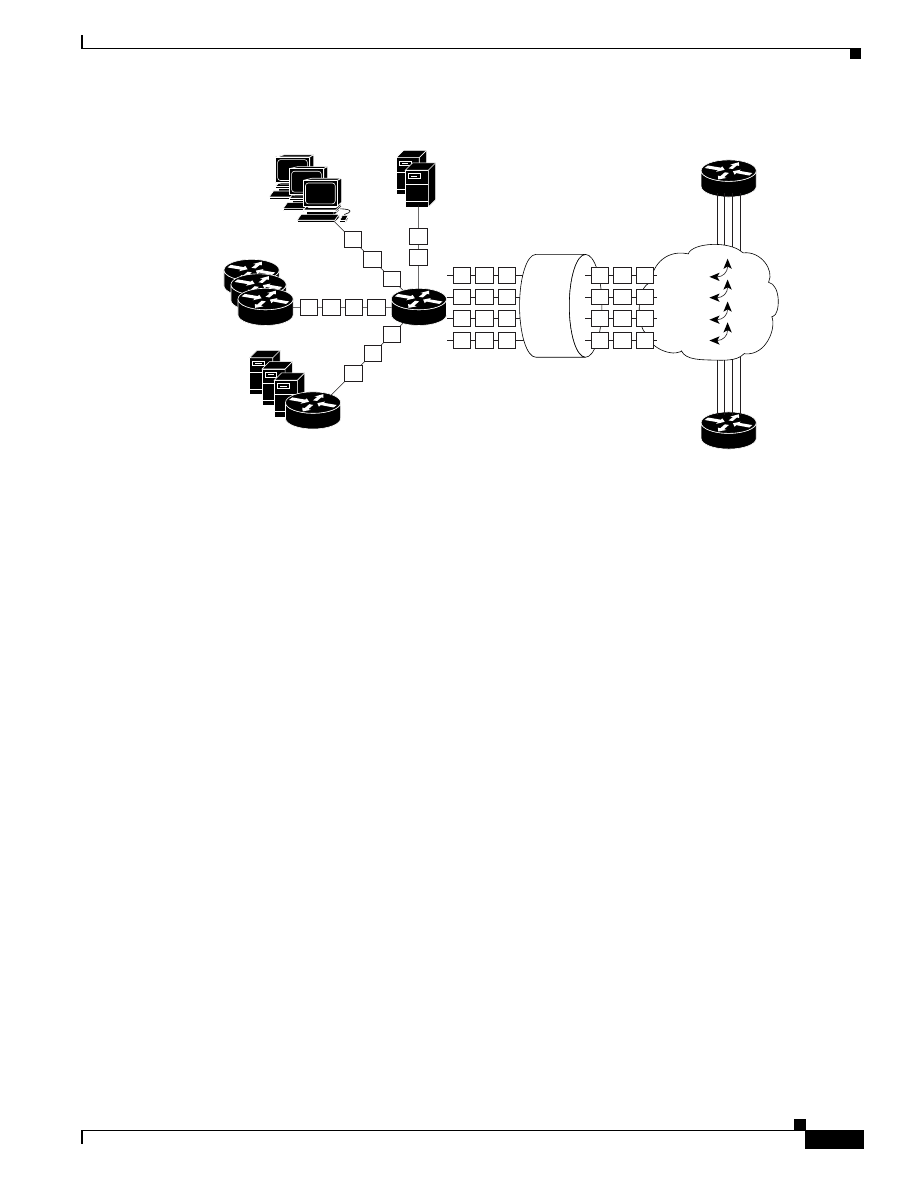
2-47
Quality of Service for Voice over IP Solutions Guide
Version 1.0
Chapter 2
QoS Features for Voice over IP
IP to ATM CoS
Figure 2-18 IP to ATM CoS Support for VC Bundles
ATM VC bundle management allows you to define an ATM VC bundle and add VCs to it. Each VC of
a bundle has its own ATM traffic class and ATM traffic parameters. You can apply attributes and
characteristics to discrete VC bundle members or you can apply them collectively at the bundle level.
To use IP to ATM CoS VC bundle for VoIP traffic, you should mark voice traffic with an IP Precedence
of 5, then map the voice traffic to a particular VC.
Using VC bundles, you can create differentiated service by flexibly distributing IP Precedence levels
over the different VC bundle members. You can map a single precedence level or a range of levels to
each discrete VC in the bundle, thereby enabling individual VCs in the bundle to carry packets marked
with different precedence levels. Some VCs in a bundle could carry voice traffic, while others could
carry non-voice data traffic. For mixed traffic, you can use WRED (or DWRED) to further differentiate
service across traffic that has different IP Precedence levels but that uses the same VC in a bundle.
To determine which VC in the bundle to use to forward a packet to its destination, the ATM VC bundle
management software matches precedence levels between packets and VCs. IP traffic is sent to the next
hop address for the bundle because all VCs in a bundle share the same destination, but the VC used to
carry a packet depends on the value set for that packet in the IP Precedence bits of the ToS byte of its
header. The ATM VC bundle management software matches the IP Precedence of the packet to the IP
Precedence value or range of values assigned to a VC, sending the packet out on the appropriate VC.
Moreover, the ATM VC bundle management feature allows you to configure how traffic will be
redirected when the VC the packet was matched to goes down.
The support of multiple parallel ATM VCs allows you to create stronger service differentiation at the
IP layer. For instance, you might want to provide IP traffic belonging to VoIP traffic on an ATM VC
with variable bit rate (VBR-rt PVC), for example, while transporting traffic other than real-time traffic
over a more elastic ATM available bit rate (ABR) PVC. Using a configuration such as this would allow
you to fully utilize your network capacity. You could also elect to transport best-effort IP traffic over an
uncommitted bit rate (UBR) PVC—UBR is effectively the ATM version of best-effort service.
27101
2
2
2
2
2
2
1
1
1
1
1
1
2
2
2
2
2
2
1
1
1
PVC 2
PVC 1
PVC 3
PVC 4
1
1
1
1
1
1
1
1
1
2
1
1
2
2
2

2-48
Quality of Service for Voice over IP Solutions Guide
Version 1.0
Chapter 2
QoS Features for Voice over IP
IP to ATM CoS
IP to ATM CoS, per-VC WFQ, and CBWFQ (Phase 3)
The IP to ATM CoS, per-VC WFQ, and CBWFQ feature with strict priority queueing allows you to
apply CBWFQ functionality—normally applicable at the interface or subinterface levels only—to an
individual VC configured for IP to ATM CoS and within CBWFQ to enable use of the strict priority
queue for VoIP traffic. You can apply strict priority queueing to a CBWFQ class so that the class gets
strict priority—that is, all of its data is sent before other classes sharing the interface are serviced.
Before looking at IP to ATM CoS, per-VC WFQ, and CBWFQ functions, consider briefly how CBWFQ
and IP to ATM CoS work independently.
CBWFQ extends the flow-based WFQ functionality to provide support for user-defined classes.
CBWFQ allows you to define traffic classes that are based on certain match criteria such as access
control lists, input interfaces names, protocols, and QoS labels. Once a class has been defined according
to its match criteria, you can assign it characteristics.
On an ATM network, you can use a VBR VC, which gives a form of strict priority, or you can use a
strict priority class for voice traffic. For strict priority classes, you do not assign bandwidth to the class,
as you would otherwise. To characterize a class, you specify the queue limit for that class, which is the
maximum number of packets allowed to accumulate in its queue. Packets belonging to a class are
subject to the queue limits that characterize the class as well as the bandwidth assigned when you enable
strict priority for the class.
After you define traffic classes, you can configure one or more of them in a policy map to be attached
as a service policy. CBWFQ allows you to create policy maps and attach them to interfaces or
subinterfaces as service policies. The IP to ATM CoS, per-VC WFQ, and CBWFQ feature allows you
to do the following:
•
Create a policy map using standard CBWFQ.
•
Within the policy map, apply the priority queueing feature, described in the “Priority Queueing
within CBWFQ” section in this chapter, to one or more classes to be used for voice traffic.
•
Apply the policy map to a VC to be used as a service policy for that VC.
Per-VC WFQ and CBWFQ allows you to differentiate the use of individual VCs within a bundle. For
instance, you can apply one service policy to one VC belonging to a VC bundle and apply a different
service policy to another VC belonging to the same bundle. You can also apply the same policy map to
multiple VCs—whether standalone or bundle members—but each VC can have only one service policy.
To concatenate service policies, you must create a third policy map and include in it all the classes that
you want to use from policy maps you would have concatenated.
The IP to ATM CoS, per-VC WFQ, and CBWFQ feature allows you to apply a policy map to a VC to
specify a service policy for that VC so that all traffic sent on that VC is categorized according to the
classes and their match criteria defined by the service policy. In other words, IP to ATM CoS, per-VC
WFQ, and CBWFQ takes the functionality defined for standard CBWFQ and for use of strict priority
within CBWFQ and makes it available for application and use at the discrete VC level.
IP to ATM CoS allows you to configure a single, standalone VC or individual VCs belonging to a
bundle. You also can configure collectively all VCs belonging to a bundle. However, for the IP to ATM
CoS, per-VC WFQ, and CBWFQ feature, you can configure individual VCs only. That is, you can
configure a standalone VC or a VC that belongs to a bundle, but you cannot use per-VC WFQ and
CBWFQ to configure a bundle of VCs collectively.
Note
For ATM, you cannot use RSVP or IP RTP Priority to give voice traffic strict priority
queueing; these constraints render strict priority queueing with CBWFQ all the more
requisite for voice traffic.

2-49
Quality of Service for Voice over IP Solutions Guide
Version 1.0
Chapter 2
QoS Features for Voice over IP
Signalling
Although CBWFQ allows you to guarantee bandwidth allocation to a voice class that is a strict-priority
class, this act alone will not eliminate jitter because CBWFQ will eventually service data queues. If one
of those data queues contained a large packet—for instance, a 1500-byte packet—onset servicing of the
data packet after the strict priority queue contents were exhausted might detain delivery of voice traffic
subsequently enqueued to the strict priority queue. Moreover, on ATM networks, you cannot fragment
large, delay-inducing packets.
If your network usage shows a preference for voice over data at the expense of data, you could allocate
all available bandwidth up to 75 percent to the voice class or queue. This circumvention is considered
an imperfect solution because eventually the data traffic would be sent in a best-effort fashion,
introducing some jitter to voice traffic.
Signalling
True end-to-end QoS requires that every element in the network path—switch, router, firewall, host,
client, and so forth—deliver its part of QoS, and that all of these entities be coordinated with QoS
signalling. To achieve end-to-end QoS, signalling must span the entire network.
An aspect of providing QoS signalling for VoIP is not to allow the call to be passed onto the IP network
unless sufficient resources are available. This feature is called Call Admission Control (CAC).
Mechanisms that implement CAC involve the router maintaining a knowledge of the IP network and
determining if there is enough bandwidth to allow the call to be placed as a VoIP call. If the bandwidth
is not sufficient, the router would signal back to the originating device that the call should be placed via
alternative means.
This section describes RSVP, which is a signalling and resource reservation protocol that also provides
CAC. This section also describes the problems that exist today in relation to use of RSVP for voice
applications.
Tips
If you choose not to use RSVP, you should ensure that voice call patterns do not
oversubscribe the available bandwidth of the network. The usual way to ensure this is to
overlay the worst-case scenario, the calling pattern of the busiest hour, onto the network
and ensure that the required traffic can be accommodated by network trunks. If the
network can accommodate the traffic, CAC is unnecessary; thus RSVP is not needed.
Alternatively, you could design your network to limit the number of voice ports so that
there can never be too many voice calls for the carrying capacity of any particular trunk.
RSVP
RSVP, which runs over IP, allows applications to dynamically request and reserve network resources
that meet their specific and stringent QoS requirements. RSVP is the first significant industry-standard
protocol for dynamically setting up end-to-end QoS across a heterogeneous network. RSVP provides
guaranteed service and admission control. It uses out-of-band signalling, a method of signalling in
which hosts send additional packets beyond data packets—that is, out-of-band packets—to indicate that
a certain QoS service is desired for a particular traffic flow.
RSVP is a setup protocol used by a host to request specific qualities of service from the network for
particular application flows. RSVP is also used by routers to deliver QoS requests to other routers (or
other types of nodes) along the path(s) of a flow. RSVP requests generally result in resources being
reserved in each node along the path.

2-50
Quality of Service for Voice over IP Solutions Guide
Version 1.0
Chapter 2
QoS Features for Voice over IP
Signalling
For networks supporting VoIP, RSVP—in conjunction with features that provide queueing, traffic
shaping, and voice call signalling—can provide call admission control for voice traffic. Call admission
control determines whether a voice call should be accepted or denied based on available resources. At
the present time, there are a number of problems pertaining to use of RSVP for voice applications. After
these problems are explained, this section describes how RSVP works.
Current Limitations of RSVP in Relation to Voice Applications
Here are the three main problems that exist in relation to use of RSVP for voice applications:
•
Resource-based admission control is not synchronized with voice call signalling.
The resource-based admission control process is not initiated until Q.931 signalling within H.323
or Session Initiation Protocol (SIP) signalling makes known the destination gateway port numbers.
Because of this sequence of events, the voice call signalling process is almost always completed
before the resource-based admission control process can commence.
If the required resources could not be reserved, the resource-based admission control process would
fail. Given the sequence of events, RSVP notification of failure may occur after the destination
phone had been picked up or while it was ringing. In either case, it would be too late to tear down
the link for the voice call. The quality of the call would be poor, because it would have gone through
without the guarantees of RSVP. The poor quality might exist for the duration of the call. If, during
the call, the RSVP reservation were accepted, the call quality would improve. However, even if the
RSVP reservation were initiated at a later stage while the call was still active, it could fail again
due to insufficient resources.
•
Bandwidth made available through CRTP is not recognized by RSVP. Thus, additional voice calls
that could have been accommodated would be rejected or they would receive best-effort service.
The terminating gateway or the end station requests for full bandwidth for the voice call are based
on the negotiated codec. If RTP header compression occurs through use of CRTP on any links
throughout the end-to-end path, the bandwidth made available through flow compression is not
recognized. Although the bandwidth is available for other uses, loss of use of it for the voice
application can have considerable, negative effect, especially on low-bandwidth access links. That
is, based on the bandwidth made available through CRTP compression but not accessible to the
voice application, a certain number of calls are rejected or given best-effort service due to
admission control. On low bandwidth links, it is important to make use of the entire (actual)
available bandwidth to put calls through, not just the bandwidth amount specified on the RSVP
RESV (reservation) message.
•
RSVP uses WFQ and does not give strict priority to voice traffic.
Voice traffic requires strict priority so as to minimize delay and jitter. The end-to-end delay
restriction for voice traffic is 150 ms. Although WFQ includes a strict priority queue, this queue is
not yet used by RSVP. Rather, RSVP relies on WFQ to provide fairness among flows, assigning a
low weight to the queue for the voice flow to give it priority. This priority is insufficient to minimize
the jitter for voice traffic.
These restrictions on the ability of RSVP to fully utilize bandwidth resulting from compression and to
provide voice applications with the strict priority service it requires are being addressed and will be
resolved in future release of Cisco IOS software.

2-51
Quality of Service for Voice over IP Solutions Guide
Version 1.0
Chapter 2
QoS Features for Voice over IP
Signalling
How RSVP Works
RSVP works in conjunction with mechanisms at end systems to request services. To ensure that QoS
conditions are met, RSVP clients provide the intermediate network nodes an estimate of the data traffic
they will generate. This information is provided with a traffic specification and a service-request
specification.
RSVP uses WFQ. When an intermediate router agrees to an RSVP request, RSVP sets up a queue for
traffic within the reserved conversation and allocates enough weight to the queue to give absolute
priority over the interface to the bandwidth requested. If the reserved traffic does not use all of the
bandwidth, other traffic on the interface will be able to use it.
RSVP offers these benefits:
•
Bandwidth guarantee. An RSVP reservation, if accepted, will guarantee that those reserved
resources will continue to be available while the reservation is in place.
•
Media independent reservation. An end-to-end RSVP reservation can span arbitrary lower layer
media types.
•
A topology-aware reservation. Once an RSVP reservation is accepted, the subsequent RSVP flows
belonging to that reservation will follow the reserved network path.
•
Data classification. While a reservation is in place, data packets belonging to that RSVP flow are
separated from other packets and forwarded as part of the reserved flow.
•
Data policing. Data packets belonging to an RSVP flow that exceed the reserved bandwidth size are
marked with a lower packet precedence.
RSVP is used by a host to request specific qualities of service from the network for a particular traffic
classification or application flow. RSVP is also used by routers to deliver QoS to other routers or nodes
along the path of a flow. RSVP requests generally result in resources being reserved in each node along
a path.
RSVP operates in tandem with unicast and multicast routing protocols. RSVP, itself, is not a routing
protocol. A routing protocol determines where packets get forwarded; RSVP is concerned with the QoS
those packets receive. RSVP consults the local unicast or multicast routing database to obtain routes.
RSVP requests for a specific QoS are made by the receiver, not the source. Putting the onus on the
receiver allows RSVP to scale to very large multicast groups. That is, receiver-oriented reservation
requests can more easily accommodate large groups, dynamic group membership, and heterogeneous
receiver requirements. Receiver-oriented reservation requests merge as they progress up the multicast
tree.
RSVP is a setup protocol that allows applications, such as voice applications, that require guaranteed
bandwidth for successful operation to request it. The need for network resource reservations differs for
voice traffic and data traffic in these ways:
•
Voice traffic experiences problems when operating over datagram services. Voice traffic sends an
almost constant flow of information, so the transmission must embody constancy. Some guarantee
must be provided that service between real-time hosts will not vary. Routers operating on a FIFO
basis risk unrecoverable disruption of the real-time information that is being sent.
RSVP mechanisms enable real-time traffic to reserve resources necessary for consistent latency.
RSVP checks and repeats reservations at regular intervals. By this process, RSVP can adjust and
alter the path between RSVP end systems from router changes. However, RSVP entails a number
of limitations in regard to voice traffic. For details, see the “Current Limitations of RSVP in
Relation to Voice Applications” section in this chapter.

2-52
Quality of Service for Voice over IP Solutions Guide
Version 1.0
Chapter 2
QoS Features for Voice over IP
Signalling
•
Data traffic seldom needs reserved bandwidth because internetworks provide datagram services for
it. This asynchronous packet switching does not need guarantees of quality of service. Routers can
operate in a FIFO manner for data traffic packets. End-to-end controls between data traffic senders
and receivers help ensure adequate transmission of bursts of information.
For RSVP, a set of packets is treated like a flow and the manner in which its treatment is specified is
known as a flow specification, referred to as a flowspec. The flowspec describes the traffic sent and the
service requirements of an application, which results in a request for the desired QoS. The flowspec can
be considered to represent a reservation request.
In addition to a flowspec, reservation requests also consist of a filterspec. The filterspec specifies those
packets that will be serviced by the flowspec. Think of a flowspec as defining the QoS and a filterspec
as qualifying certain traffic for the QoS.
RSVP implements QoS for a particular flow using mechanisms collectively called traffic control. These
mechanisms include:
•
A packet classifier that determines the QoS class, and perhaps the router, for each packet.
•
An admission control function that determines whether the node has sufficient available resources
to supply the requested QoS.
•
A packet scheduler that determines when particular packets are forwarded to meet QoS
requirements of a flow.
Consider how these aspects of RSVP work together to create a reservation. A host uses RSVP to request
a specific QoS service from the network on behalf of an application data stream. To ensure that QoS
conditions are met, RSVP clients provide the intermediate network nodes an estimate of the data traffic
they will generate.
RSVP requests the particular QoS, but it is up to the interface queueing mechanism to implement the
reservation. RSVP carries the request through the network, visiting each node the network uses to carry
the stream. At each node, RSVP attempts to make a resource reservation for the stream using its own
admission control module, exclusive to RSVP, which determines whether the node has sufficient
available resources to supply the requested QoS.
If either resources are unavailable or the user is denied administrative permission, the RSVP program
returns an error notification to the application process that originated the request. If both attempts
succeed, the RSVP daemon sets parameters in a packet classifier and packet scheduler to obtain the
desired QoS. The packet classifier determines the QoS class for each packet and the scheduler orders
packet transmission to achieve the promised QoS for each stream.
WFQ (or WRED) sets up the packet classification and the scheduling required for the reserved flows.
Using WFQ, RSVP can deliver an integrated services guaranteed rate service. Using WRED, RSVP can
deliver a controlled load service.

C H A P T E R
3-1
Quality of Service for Voice over IP Solutions Guide
Version 1.0
3
Providing Branch Office Site Users and
Telecommuters VoIP Access to the Main
Campus
This chapter explores the quality of service (QoS) for Voice over IP (VoIP) features deployed for the
various links of an end-to-end VoIP path throughout a corporate network that encompasses a main
enterprise campus network with remote branch offices and telecommuters. The chapter explains how to
configure these QoS features for optimum voice quality delivery.
This chapter includes the following sections:
•
Scenario Description
•
Providing Small Branch Office Users Access Across 64-K Links
•
Providing Medium Size Branch Office Users QoS for VoIP Access to the Main Campus Using T1
Links
Scenario Description
The chapter addresses a scenario that illustrates how to deploy QoS features for the links comprising
segments of an end-to-end VoIP path through a corporate campus (enterprise) network that has been
rearchitected to carry packetized voice in addition to regular data. (QoS for VoIP configuration for
segments of the end-to-end path are described in their own sections in this chapter.) The complete
end-to-end path gives VoIP access to all corporate members. All employees—those who work at the
main campus, the branch offices, and at home—use VoIP for telephone communication with other
employees.
The internetwork that includes the campus network encompasses Internet Service Provider (ISP) and
Wide Area Network (WAN) networks. The campus network remote branch offices are connected to the
main campus through WAN links, which also interconnect the campus network to the ISP. This chapter
focuses exclusively on the end-to-end path across the campus network, but users could make calls to
and receive them from other users across the internetwork.
Figure 3-1 shows the complete end-to-end QoS for VoIP path throughout the corporate campus—but in
this case the path is shown in relation to the entire internetwork of which it is a part.
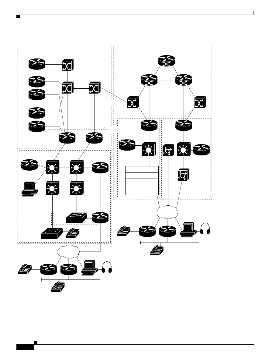
3-2
Quality of Service for Voice over IP Solutions Guide
Version 1.0
Chapter 3
Providing Branch Office Site Users and Telecommuters VoIP Access to the Main Campus
Scenario Description
Figure 3-1
QoS for VoIP Path for Main Campus, Branches, and Telecommuters within the Complete Internetwork
V
Large
branch
office
T1>
(Frame)
DS-3
ATM
7206
7206
7505
IGX
GSR
ATM
(OC-12c)
GSR
SP-POP
POS (OC-48)
POS
(OC-3c)
ATM (OC-3c)
ATM
(OC-3c)
8850
GSR
SP-POP
7507
7507
PRIs
5800
Catalyst
AP-
VS3
Catalyst
POS (OC-12c)
POS
(OC-3c)
ATM (OC-3c)
ATM
(OC-3c)
8850
LightStream
1010
IGX
3640
2600
ATM
(DS-3)
T1-
PPP
3640
Branch
office
T1-
Frame
64-K
PPP
2600
Small
branch
office
64-K
Frame
DS-3 Fast Packet
Campus branch offices
SP-Backbone
A
TM (OC-3c)
Directory-
Gatekeeper
3640
ISP-
Dialup
5300
3640
Gatekeeper
PRI
Campus
IP Phone
IOS
Gatekeeper
Closet Switches
Catalyst 4000
Catalyst 2924 XL
Catalyst 5x00
Catalyst
85xx
PBX
Interconnect
AS5300
Ethernet
Catalyst
85xx
Catalyst
85xx
Catalyst
85xx
Catalyst
85xx
Server Farm
Catalyst 5x00
PSTN
IP Phone
804
FXS
Analog
BRI
BRI
2600
ATM (OC-3c)
DS-3 PPP
26513
Catalyst 5002
7206
3640 - Gatekeeper
AS5300
(12)
PSTN
IP Phone
804
FXS
Analog
BRI
BRI
2600

3-3
Quality of Service for Voice over IP Solutions Guide
Version 1.0
Chapter 3
Providing Branch Office Site Users and Telecommuters VoIP Access to the Main Campus
Scenario Description
Although all voice communication occurs over VoIP, the underlying link technology differs for the
various segments of the end-to-end VoIP path into and out from the campus. Table 3-1identifies each of
the path segments and gives their link characteristics
.
The end-to-end QoS for VoIP path throughout the corporate network allows for all variations of
caller-to-called relationships. For instance, a call could be placed by a user at the small branch office or
the medium size branch office and terminate at a telecommuter’s home phone. Here is a summary of the
relationships the QoS for VoIP end-to-end path enables within the campus network:
•
Branch office users can call other branch office users, users in the main campus, and telecommuters.
•
Telecommuters can call other telecommuters, users in the main campus, and branch office users.
•
Main campus users can call other main campus users, branch office users, and telecommuters.
Table 3-2 shows the salient hardware features for the corporation’s network.
Table 3-1
Link Type for Segments of the Campus QoS for VoIP End-to-End Path
Use of Segment
Link Type
Access to and from small branch
office
•
64-K Point-to-Point Protocol (PPP)
or
•
64-K Frame Relay
Access to and from medium
branch office
•
T1 (1.544 Mbps) Frame Relay
or
•
T1 (1.544 Mb) PPP
Access to and from
telecommuters
•
Access over a PSTN using ISDN or analog dial connectivity.
Table 3-2
Campus Routers and Switches Used in End-to-End QoS for VoIP Path
Router
Location in End-to-End Path
Use
Cisco 2600 router
Small branch office
VoIP gateway.Converts digital
phone calls into packetized
(analog) voice traffic, and the
reverse.
Cisco 3640 router
Medium size branch office
VoIP gateway. Converts digital
phone calls into packetized
(analog) voice traffic, and the
reverse.
Cisco 7206 router
Campus access from and to the
branch offices
Aggregate router for corporate
leased lines and
packet-switched lines.
Catalyst 8500 switches
Packet switching within the main
campus
Core and distribution routers
within the main campus
network.
Cisco 5300 router
PBX interconnect from and to
the PSTN used by
telecommuters.
VoIP gateway. Supports ISDN
PRI channels and analog phone
line calls from and to the PSTN.

3-4
Quality of Service for Voice over IP Solutions Guide
Version 1.0
Chapter 3
Providing Branch Office Site Users and Telecommuters VoIP Access to the Main Campus
Providing Small Branch Office Users Access Across 64-K Links
Providing Small Branch Office Users Access Across 64-K Links
This section describes the QoS for VoIP configuration for the following two types of links, either of
which could be used to provide VoIP access to and from the small branch office users so that they can
communicate with one another, main campus users, and telecommuters:
•
Using a 64-K PPP Link
•
Using a 64-K Frame Relay Link
This topology configuration assumes that the small branch office site accommodates 100 or fewer users.
Using a 64-K PPP Link
This section describes the link type and the QoS features for VoIP you should use for a 64-K PPP link
and configuration.
64-K PPP Link Type and Configuration
The campus (corporate) network provides a 64-K PPP link for access to and from the small branch
office and main campus. This link is directly connected to the Cisco 7206 router giving access to the
main campus. Because the 64-K PPP link is a slow-speed link, it requires use of specific QoS features
different from those used for a faster speed link, such as a T1 line. For instance, to obviate (or at least
control) delay and jitter, a slow-speed link requires that large data packets be fragmented and
interleaved with voice packets.
Most of the same QoS features used for the 64-K Frame Relay link (described in “Using a 64-K Frame
Relay Link” section on page 3-10) are also used for PPP. Both PPP and Frame Relay 64-K links require
use of priority queueing in order to grant voice the strict priority it requires. They both also require use
of CRTP to compress the large RTP header to provide greater throughput. Fragmentation of large data
packets is done on both links, but using different QoS technologies. Link Fragmentation and
Interleaving (LFI) is supported on PPP links, whereas FRF.12 is supported on Frame Relay links for the
same purpose.
Figure 3-2 shows the path from the 2600 router at the small branch office which is directly connected
via the 64-K PPP link to the 7206 campus access router into the main campus. The 2600 router at the
small branch office is configured as a VoIP gateway that allows for codec conversion (using G.729a) of
analog voice to packetized digital voice and back. Users throughout the branch office can make phone
calls to users throughout the main campus and telecommuters. Routed through the gateway, their analog
calls are converted to packetized digital data transmitted using VoIP.
This portion of the configuration focuses on the path segment from the 2600 router to 7206 router.
However, Figure 3-2 shows the full path through the campus to the PBX interconnect 5300 router.
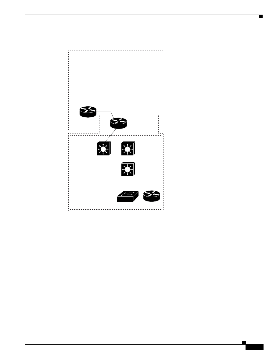
3-5
Quality of Service for Voice over IP Solutions Guide
Version 1.0
Chapter 3
Providing Branch Office Site Users and Telecommuters VoIP Access to the Main Campus
Providing Small Branch Office Users Access Across 64-K Links
Figure 3-2
End-to-End QoS for VoIP Path Between a Small Branch Office Router and Campus Access
Over a 64-K PPP Link
Configuring QoS for VoIP on a 64 K PPP Link
This section describes the configuration for deploying the following QoS for VoIP features for the 64-K
PPP link:
•
Compressed Real-Time Protocol (CRTP)—Used to compress the large RTP header.
•
Link Fragmentation and Interleaving (LFI)—Used as the large data packet fragmentation and
interleaving mechanism.
•
IP RTP Priority queueing (Also referred to as Priority Queueing-Weighted Fair Queueing
(PQWFQ))—This feature is used as the queueing mechanism to give voice traffic strict priority
service.
Example 3-1 shows the configuration commands for the 2600 router 64-K PPP link with the commands
for the QoS features called out in bold.
7206
2600
64-K
PPP
Small
branch
office
Campus branch offices
Campus
PBX
Interconnect
Cisco AS5300
Catalyst
85xx
Catalyst
85xx
Catalyst
85xx
Server Farm
Catalyst 5x00
27280

3-6
Quality of Service for Voice over IP Solutions Guide
Version 1.0
Chapter 3
Providing Branch Office Site Users and Telecommuters VoIP Access to the Main Campus
Providing Small Branch Office Users Access Across 64-K Links
Example 3-1
64-K PPP Link Configuration with QoS for VoIP
interface Loopback 0
ip address 10.14.26.26 255.255.255.0
h323-gateway voip interface
h323-gateway voip id r1-3640a-gk.cisco.com ipaddr 10.12.254.3 1719
h323-gateway voip h323-id r1-2600@cisco.com
!
interface Serial0/1
bandwidth 64
ip address 10.14.97.2 255.255.252
encapsulation PPP
ppp multilink
multilink-group 1
!
interface multilink 1
ip unnumbered Serial0/1
ip rtp header-compression iphc-format
ip tcp header-compression iphc-format
fair-queue 64 256 0
ppp multilink
ppp multilink fragment-delay 20
ppp multilink interleave
ip rtp priority 16384 16384 48
Configuring a Multilink Interface with QoS for VoIP Features
This section describes the QoS features you configure for the PPP link using a multilink interface. Most
of these QoS features are the same as those that you configure for a Frame Relay 64-K link. Therefore,
instead of repeating conceptual information, these steps refer to the related Frame Relay sections that
cover configuration steps for common features.
Note
This configuration process provides two alternative ways of configuring strict priority
queueing for VoIP traffic. In this set of steps, both methods are presented as Step 2. The
first Step 2 shows how to configure strict priority using IP RTP Priority. The second
(alternative) Step 2 shows how to configure strict priority queueing using strict priority
within CBWFQ.
Step 1: Configure CRTP for the PPP Link
To enable RTP header compression, perform the following task in interface configuration mode (you
need to enable compression on both ends of the connection).:
For background information on CRTP, see the “Step 1: Configure CRTP for a 64-K Frame Relay Link”
section. Also, see Chapter 2, “About QoS Features for Voice.”
Command
Purpose
ip rtp header-compression iphc-format
Enables RTP header compression for VoIP
packets.

3-7
Quality of Service for Voice over IP Solutions Guide
Version 1.0
Chapter 3
Providing Branch Office Site Users and Telecommuters VoIP Access to the Main Campus
Providing Small Branch Office Users Access Across 64-K Links
Step 2: Configure WFQ and Enable the Strict Priority Queue for VoIP Packets on the PPP Link
When WFQ is enabled, it creates a strict priority queue that exists potentially for use by delay-sensitive
traffic such as voice traffic. However, the strict priority queue cannot be used until it is enabled through
configuration of the ip rtp priority command. This section gives the command syntax for the
fair-queue and ip rtp priority commands that you use to enable WFQ and its strict priority queue.
To enable WFQ for the PPP interface shown in Example 3-1, set the congestion threshold after which
messages for high-bandwidth conversations are dropped, and specify the number of dynamic and
reservable queues, perform the following task in interface configuration mode after specifying the
interface:
To reserve a strict priority queue for a set of RTP voice packet flows belonging to a range of UDP
destination ports, use the following command in interface configuration mode:
For background information on WFQ and the strict priority feature, see the “Step 2: Configure WFQ
and Enable the Strict Priority Queue for VoIP Packets on the PPP Link” section. Also, see Chapter 2,
“About QoS Features for Voice.”
Step 2: Alternative Configuration: Configure WFQ and Enable the Strict Priority Queue within CBWFQ for a 64 K PPP Link
This step provides an alternative method of giving voice traffic strict priority queueing. It describes how
you can use the same feature described in the first Step 2, but within CBWFQ to apply strict priority
queueing to a CBWFQ class used for voice traffic.
Command
Purpose
fair-queue 64 256 0
Configures the PPP interface to use weighted fair
queueing with a congestive discard threshold of
64, 256 dynamic queues, and no reservable
queues.
Command
Purpose
ip rtp priority 16384 16383 48
Reserves a strict priority queue for the VoIP
packet flow using destination ports in the range of
16384 and 16383. VoIP flows for the example PPP
link whose UDP destination ports are within the
range of 16384 and 16383 are granted strict
priority with a bandwidth guarantee of 48 kbps.
The example configuration is designed to service
4 voice calls at the cost of 12 K per call. For your
configuration, assume that each call consumes 12
K and set the bandwidth parameter to the result of
the following equation:
bandwidth
= 12K x
number-of-calls
The IP RTP Priority feature does not require that
you know the port of a voice call. Rather, the
feature gives you the ability to identify a range of
ports whose traffic is put into the priority queue.
Moreover, you can specify the entire voice port
range—16384 to 32767—to ensure that all voice
traffic is given strict priority service.

3-8
Quality of Service for Voice over IP Solutions Guide
Version 1.0
Chapter 3
Providing Branch Office Site Users and Telecommuters VoIP Access to the Main Campus
Providing Small Branch Office Users Access Across 64-K Links
Priority queueing within CBWFQ enables use of the strict priority queue implicit to WFQ. Although it
is possible to enqueue various types of real-time traffic to the strict priority queue, it is strongly
recommended that you direct only voice traffic to it. This recommendation is made because voice traffic
is well-behaved, whereas other types of real-time traffic are not. Moreover, voice traffic requires that
delay be nonvariable in order to avoid jitter. Real-time traffic such as video could introduce variation in
delay thereby thwarting the steadiness of delay required for successful voice traffic transmission. For
complete information the Priority Queueing within CBWFQ feature, see Chapter 2, “QoS Features for
Voice over IP.”
This section gives the command syntax for the fair-queue and ip rtp priority commands that you use
to enable WFQ and its strict priority queue.
To enable weighted fair queueing for the PPP interface shown in Example 3-1, set the congestion
threshold after which messages for high-bandwidth conversations are dropped, and specify the number
of dynamic and reservable queues, perform the following task in interface configuration mode after
specifying the interface:
To create a class for voice called “class voice” and configure that class as a strict priority class with a
bandwidth allocation of 50 kbps, use the following commands beginning in interface configuration
mode:
Step 3: Configure Link Fragmentation and Interleaving for a 64-K PPP Link
Because voice packets are small in size and can be detained between large data packets sent out the same
interface, you should use LFI on slow-speed PPP links. (When you enable LFI, large data packets are
fragmented and the small voice packets are interleaved between the data fragments.)
Command
Purpose
fair-queue 64 256 0
Configures the PPP interface to use weighted fair
queueing with a congestive discard threshold of
64, 256 dynamic queues, and no reservable
queues.
Command
Purpose
class-map voice
Creates a class and names it voice.
match access-group 102
Specifies that all traffic belonging to the
numbered access group 102 will belong to the
voice class.
policy-map voiceplus
Creates a policy map called voice to be applied to
the interface.
class voice
Adds the class called voice to the policy map
voiceplus.
priority 50
Enables the strict priority queue for the class
called voice and sets the bandwidth for the voice
traffic to 50 kbps.
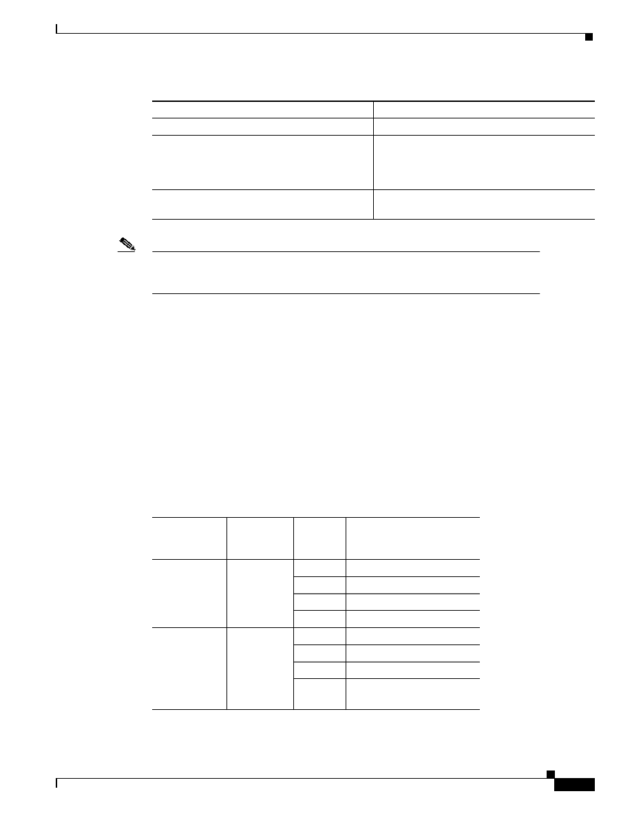
3-9
Quality of Service for Voice over IP Solutions Guide
Version 1.0
Chapter 3
Providing Branch Office Site Users and Telecommuters VoIP Access to the Main Campus
Providing Small Branch Office Users Access Across 64-K Links
To configure LFI on a 64-K PPP link, use the following commands:
Note
At higher link rates, the bandwidth savings of CRTP may be outweighed by additional
CPU load. For slow-speed links, CPU utilization is generally not very high. However, you
can monitor CPU utilization to ensure that it is not above 75% when CRTP is configured.
Outcome Measurements for a 64-K PPP Link QoS for VoIP Configuration
To convey a sense of how application of QoS features affects the quality of voice transmission, this
section provides measurements that show a set of results produced when the following criteria, shown
in Table 3-3, vary:
•
QoS Feature Used. This column identifies which QoS features were configured to satisfy voice
traffic requirements and improve voice quality.
•
Concurrent TCP Data Traffic (noise level). This column identifies the amount of data traffic
transmitted on the same line as voice.
•
Number of Voice Calls: This column gives the throughput—the number of voice calls put through
for the test.
•
Average PSQM Score
Command
Purpose
ppp multilink
Enables MLP on the PPP link.
ppp multilink fragment-delay 20
Configures a maximum fragment delay of 20 ms.
This gives the voice stream a maximum bound on
delay of 20 ms. In this case MLP will choose a
fragment size based on the configured value.
ppp multilink interleave
Enables real-time packet interleaving on the PPP
link
Table 3-3
Voice Call and Quality Measurements for 64-K PPP
QoS Feature
Used
Concurrent
TCP Data
Traffic
Number of
Voice
Calls
PSQM Score
Average
Without QoS
(to establish
baseline)
none
(baseline)
1
1.69542
2
1.74596
3
2.0772
4
2.08331
WFQ
55 kbps
19 pps
5% CPU
2 TCP
streams
1
2.73794
2
3.38811
3
3.76196
4
4.99414

3-10
Quality of Service for Voice over IP Solutions Guide
Version 1.0
Chapter 3
Providing Branch Office Site Users and Telecommuters VoIP Access to the Main Campus
Providing Small Branch Office Users Access Across 64-K Links
Using a 64-K Frame Relay Link
This section describes the link type, the QoS features for VoIP you should use for this type of link and
circumstance, and how to handle conditions you might encounter that could negatively affect voice
traffic.
64-K Frame Relay Link Type and Configuration
The campus (corporate) network provides a 64-K Frame Relay link for access to and from the small
branch office and main campus. This link connects from the small branch office 2600 router through
the IGX switch to the T1 Frame Relay link. The T1 Frame Relay link gives access to the campus through
the 7206 router. Although not shown in the illustrations depicting this scenario or path segment,
connected to the small branch office 7206 router is the network used by the 100 or so employees
comprising the small branch office group. Let’s assume that the small branch office network uses
fast-speed (10-to-100 Mb Ethernet) links. Because the Ethernet links provide greater bandwidth (and,
thus, faster speed) than does the 64-K Frame Relay link out from the campus, the 64-K Frame Relay
link is the bottleneck in this path. All of the QoS for VoIP features used in the configuration muster
against occurrence of congestion.
Because it is a slow-speed link, the 64-K Frame Relay link requires use of specific QoS features
different from those used for a faster speed link, such as a T1. For instance, to obviate (or at least
control) delay and jitter, a slow-speed link requires that large data packets be fragmented and
interleaved with voice packets. Moreover, traffic coming into the network across the fast-speed LAN
links must be shaped as it leaves the router to accommodate the slower-speed 64-K line and to ensure
that bursting does not occur. (For slow-speed Frame Relay links, you control packet drop by configuring
FRTS to ensure against bursting.)
Figure 3-3 shows the path from the 2600 router at the small branch office which connects through the
IGX switch to the 7206 campus access router, then into the main campus and out through the 5300
router across the PSTN, giving voice access to all corporate users. The 2600 router at the small branch
office is configured as a VoIP gateway that allows for codec conversion (using G.729a) of analog voice
CBWFQ
55 kbps
19 pps
5% CPU
2 TCP
streams
1
2.87017
2
2.40119
3
4.21419
4
n/a
PQWFQ
(Priority
Queueing within
CBWFQ)
55 kbps
19 pps
5% CPU
2 TCP
streams
1
2.062
2
2.12987
3
1.91315
4
2.3743
Table 3-3
Voice Call and Quality Measurements for 64-K PPP (continued)
QoS Feature
Used
Concurrent
TCP Data
Traffic
Number of
Voice
Calls
PSQM Score
Average
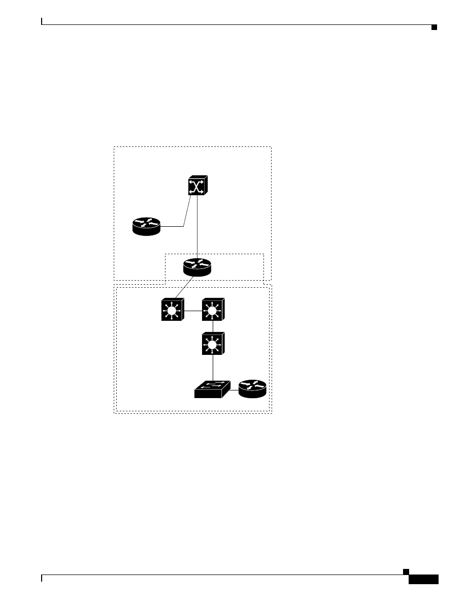
3-11
Quality of Service for Voice over IP Solutions Guide
Version 1.0
Chapter 3
Providing Branch Office Site Users and Telecommuters VoIP Access to the Main Campus
Providing Small Branch Office Users Access Across 64-K Links
to packetized digital voice and back. This QoS for VoIP configuration focuses on the 64-K Frame Relay
link. Figure 3-3 shows the full path from the 2600 router through the IGX switch and 7206 router into
the campus, then to the PBX interconnect 5300 router.
The main campus network encompasses Catalyst 8500 series switches with fast-speed (10-to-100 Mbps
Ethernet) links. Traffic from multiple applications aggregates across the campus Ethernet links.
Figure 3-3
Path Between a Small Branch Office and the Main Campus Router Across a 64-K Frame
Relay Link
Configuring QoS for VoIP on a 64-K Frame Relay Link
This section describes the configuration for deploying the following QoS for VoIP features on the
outbound interface and at the PVC level for the 64-K Frame Relay link:
•
Compressed Real-Time Protocol (CRTP)—Used to compress the large RTP header.
•
Frame Relay Traffic Shaping (FRTS)—Used to shape traffic leaving the 2600 router to meet the
64-K Frame Relay link constraints in order to avoid packet loss and smooth out bursts.
•
Frame Relay Fragmentation 12 (FRF.12)—Used as the fragmentation and interleaving mechanism.
•
IP RTP Priority queueing—Also referred to as Priority Queueing-Weighted Fair Queueing
(PQWFQ), is used as the queueing mechanism to give voice traffic strict priority service and service
data traffic with WFQ.
64-K
Frame Relay
7206
IGX
2600
Small
branch
office
64-K
Frame
Relay
Small branch offices
Campus
27279
PBX
Interconnect
Cisco AS5300
Catalyst
85xx
Catalyst
85xx
Catalyst
85xx
Server Farm
Catalyst 5x00

3-12
Quality of Service for Voice over IP Solutions Guide
Version 1.0
Chapter 3
Providing Branch Office Site Users and Telecommuters VoIP Access to the Main Campus
Providing Small Branch Office Users Access Across 64-K Links
Example 3-2 shows the configuration commands for the 2600 router with the commands for the QoS
features called out in bold. In this example, subinterface Serial10/1.64 is configured for the Frame
Relay PVC.
To register the router as a gateway with the gatekeeper, the router is configured with a loopback
interface. The loopback is used so that the gateway registration with the gatekeeper remains relatively
stable even if the gatekeeper cannot contact the gateway router when updating its tables.
The interface to the 64-K Frame Relay link at the 2600 router in the small branch office and the 7206
router at the campus access have mirroring configurations, using the same QoS features. Because they
are largely the same, this section describes the QoS configuration for the 2600 router only. CRTP and
FRTS must be enabled at the interface level. Though you enable FRTS at the interface level, you
configure it at the PVC level. At the PVC level, FRF.12, IP RTP Priority queueing, the Frame Relay
committed information rate (CIR), the Frame Relay minimum committed information rate (MINCIR),
and WFQ parameters are configured; these QoS features are configured within a Frame Relay map class
called voice that is applied to the PVC.
Example 3-2
64-K Frame Relay Link Configuration with QoS for VoIP
interface Loopback 0
ip address 10.14.26.26.255.255.255.0
h323-gateway voip interface
h323-gateway voip id r1-3649a-gk.Cisco.com ipaddr 10.12.254.3 1719
h323-gateway voip h323-id r1-2600@Cisco.com
!
interface Serial0/1
no ip address
encapsulation frame-relay
ip rtp header-compression iphc-format
ip tcp header-compression iphc-format
frame-relay traffic-shaping
!
interface Serial0/1.64 point-to-point
ip address 10.14.97.2 255.255.255.252
frame-relay interface-dlci 64
frame-relay class voice
!
map-class frame-relay voice
frame-relay cir 64000
frame-relay mincir 48
frame-relay fragment 80
frame-relay fair-queue
ip rtp priority 16384 16383 48
Step 1: Configure CRTP for a 64-K Frame Relay Link
In a VoIP network, compression reduces the bandwidth necessary for each voice call, thus increasing
the number of calls that can be transmitted over a given link. Enabling compression is especially
necessary on a slow-speed (low-bandwidth) link in order to yield greater throughput. (You enable CRTP
on both ends of the link.)
The two portions—payload and header—of a voice packet can each be compressed. Payload
compression is determined by the codec used. CRTP is used to compress the RTP header. (CRTP
compression is applied to the voice packet header after its payload has already been reduced through
codec compression, which both converts analog to digital data and compresses the data.)

3-13
Quality of Service for Voice over IP Solutions Guide
Version 1.0
Chapter 3
Providing Branch Office Site Users and Telecommuters VoIP Access to the Main Campus
Providing Small Branch Office Users Access Across 64-K Links
To gain a sense of the bandwidth savings based on codec compression, consider this case: uncompressed
voice traffic converted by a gateway that uses codec G.711 PCM has a bandwidth requirement of 64
kbps before the RTP header overhead is accounted for. Cisco VoIP gateways can compress the voice
signal down to 8 kbps using the G.729 codec. Although the number of bytes of voice payload can be
specified as part of the codec selection, this has no effect on the RTP header added to each voice packet,
which is considerable.
To compress the IP/UDP/RTP header down to as little as 2 bytes, you use CRTP. For a G.729 call, for
instance, this results in a cost of 12K—a cost that is acceptable to most users.
Before you can enable RTP header compression, you must have configured the Frame Relay line, as
shown previously in Example 3-2.
To enable RTP header compression, perform the following task in interface configuration mode (you
need to enable compression on both ends of the connection):
Step 2: Enable FRTS at the Interface Level for a 64-K Frame Relay Link
FRTS shapes traffic to ensure that traffic conforms to the policies contracted for it. In terms of the
configuration shown in Example 3-2, the contracted policy is a link speed of 64 K. In this sense, traffic
shaping is essentially a means of limiting a router’s transmit rate toward a target destination to a specific
peak/average value that is lower than the line rate of the circuit (link speed). To this end, FRTS is used
to eliminate the possibility of traffic bursting about the committed bandwidth so as to fend against
packet loss. You enable FRTS at the interface level and configure it at the PVC level.
Use of FRTS is essential for voice traffic, which is UDP based, to prohibit bursting above the committed
information rate (CIR). For data-only networks that rely on TCP, TCP incorporates a slow-start
mechanism that allows a TCP flow between two end points to increase its effective flow rate slowly in
order to determine the minimum bandwidth link between the two endpoints. While this TCP process
negates the need for traffic shaping in data-only networks, the absence of a similar process in
UDP-based networks necessitates use of FRTS to shape traffic.
In the configuration shown in Example 3-2, FRTS is enabled for interface Serial10/1 and configured for
DLCI 64. For the PVC, the Frame Relay CIR parameter is set to 64 K (the link speed) so that traffic will
not burst above the link’s bandwidth causing loss, which would degrade voice quality. If the PVC is
congested, the traffic flow is reduced to the MINCIR configured for that PVC.
The frame-relay fair-queue command is given to enable FRTS WFQ at the PVC level. WFQ is used
as the queueing mechanism for all traffic on this PVC other than voice. WFQ does not provide strict
priority required for voice. Therefore, to give voice traffic the strict priority queueing it requires, IP RTP
Priority is configured for the PVC. (For more information, see the “About IP RTP Priority” later in this
chapter.)
At the output interface on the 7206 campus access router, traffic coming from the small branch office
fast-speed Ethernet links (ranging from 10 Mb to 100 Mb) is shaped before it leaves the router to match
the flow of the slower-speed 64-K Frame Relay link. If traffic were not shaped at the router, a bottleneck
condition could occur.
It is good policy to use FRTS for all links that carry both voice and data, regardless of the link bandwidth
capacity. Moreover, you must use traffic shaping to handle these three conditions, discussed more fully
in Chapter 2:
•
link speed mismatches
Command
Purpose
ip rtp header-compression iphc-format
Enables RTP header compression for VoIP
packets.

3-14
Quality of Service for Voice over IP Solutions Guide
Version 1.0
Chapter 3
Providing Branch Office Site Users and Telecommuters VoIP Access to the Main Campus
Providing Small Branch Office Users Access Across 64-K Links
Link speed mismatches result in congestion during which packets are queued in buffers causing
delays.
•
oversubscription
Oversubscription occurs when many remote sites feed a central site. A remote-to-central site
configuration is oversubscribed when aggregate transmission from remote sites exceeds the central
site’s link bandwidth capacity. Even if the CIRs of all the remote sites collectively are less than the
central site’s link speed, oversubscription can occur when bursting of the remote sites exceeds the
central site link speed. The topology, shown in Figure 3-1, for the example scenario, indicates that
traffic from the following three links aggregates at the 7206 campus access router:
–
The 64-K point-to-point link from the small branch office
–
The T1 link from the medium branch office, switched through the IGX to the 7206 router.
–
The DS-3 ATM link switched through the IGX to a T1 Frame Relay link connecting to the 7206
router
•
bursting
Frame Relay circuits have a link speed and an associated CIR that is in most cases less than the line
rate. The CIR is the amount of traffic that is transmitted when there is no congestion on the PVC.
When traffic bursts occur or when congestion is reported, or both events occur, the amount of traffic
transmitted is determined by the configured MINCIR, and this becomes the guaranteed minimum
committed information rate.
Many network providers allow applications to burst above the guaranteed CIR all the way up to the
line rate. It is well understand that in the event of congestion, bursting about the CIR incurs the risk
of packet loss because any data sent over the CIR is considered best-effort traffic. If you run voice
traffic across a network designed to support bursting, it is likely that voice will be included in the
excess bandwidth above the CIR because Frame Relay has no way of differentiating between voice
traffic and data traffic. If global congestion ensues, delay (caused by buffering) and packet drop
could occur. To stem the problems for voice traffic resulting from bursting, you must use FRTS on
each PVC that carries voice to ensure that the outbound traffic rate does not exceed the link’s
configured CIR. Although this could potentially reduce data throughput, it guarantees throughput
and constant delay to voice traffic even when congestion occurs.
Enabling Frame Relay traffic shaping on an interface enables both traffic shaping and per-virtual circuit
queuing on all the interface’s PVCs and SVCs. Traffic shaping enables the router to control the circuit’s
output rate and react to congestion notification information if also configured.
To enable Frame Relay traffic shaping on the specified interface, complete the following task in
interface configuration mode:
Step 3: Configure a Map Class and Apply It to the PVC for a 64-K Frame Relay Link
To configure a Frame Relay link for voice traffic, you must create a Frame Relay map class and
configure it to support voice traffic. The voice bandwidth, fragmentation size, traffic shaping attributes,
and strict priority service for voice are configured on the map class. These attributes are required for
sending voice traffic on the PVC.
In the configuration shown in Example 3-2, the data fragment size is 80 bytes, and the BE and BC traffic
shaping parameters assume their default values. For the PVC, the Frame Relay CIR parameter—which
specifies the upper bound on bandwidth allocation—is set to the link speed (64 K) so that traffic will
Command
Purpose
frame-relay traffic-shaping
Enables Frame Relay traffic shaping and
per-virtual circuit queuing.

3-15
Quality of Service for Voice over IP Solutions Guide
Version 1.0
Chapter 3
Providing Branch Office Site Users and Telecommuters VoIP Access to the Main Campus
Providing Small Branch Office Users Access Across 64-K Links
not burst above the link’s bandwidth causing loss, which would degrade voice quality. Also for the PVC,
the Frame Relay MINCIR—which establishes the lower bound on bandwidth allocation—is set 48 K,
the amount of bandwidth guaranteed to be delivered to voice traffic under congestion conditions.
Note
You must set the bandwidth amount allocated for strict priority for voice to be less than or
equal to the MINCIR. (You use the
ip rtp priority
command within the map class for voice
to configure strict priority.)
To configure QoS for VoIP at the PVC level for the 64-K Frame Relay link, you create a Frame Relay
map class. The attributes required for sending voice on the PVC are configured in the map class, which
is applied to the Frame Relay DLCI used for voice traffic through the frame-relay class voice
command.
The following topics, underlying use of these commands, are explored in this step after the
configuration commands are listed:
•
About the CIR
•
FRF.12
•
FRF and ATM
•
Using WFQ as the Data Queueing Strategy
•
Why WFQ Is Inadequate for Voice
•
About IP RTP Priority
To configure the frame-relay map class called voice, use the following commands:
Command
Purpose
map-class frame-relay voice
Specifies the Frame Relay map class
name—voice, in this case—and enters map class
configuration mode.
frame-relay cir 64000
Specifies the committed information rate (CIR) in
bits per second (bps) for the PVC. For the
example configuration, the CIR is 64000 bps.
frame-relay mincir 48
Specifies the minimum committed information
rate (MINCIR) (guaranteed for voice traffic under
congestion conditions) in bits per second (bps) for
the PVC. For the example configuration, the
MINCIR is 48 bps.
frame-relay fragment 80
Configures Frame Relay fragmentation for the
map class. The fragment_size, which is 80 bytes
for the example configuration, defines the payload
size of a fragment, and excludes the Frame Relay
headers and any Frame Relay fragmentation
header. The valid range is from 16 to 1600 bytes,
and the default is 53. (See “Determining If You
Need to Fragment Data Packets and Frames” in
Chapter 2 for optimum sizes per link type.)
The fragment_size should be less than or equal to
the MTU size. You should set the fragmentation
size such that the largest data packet is not larger
than the voice packets.

3-16
Quality of Service for Voice over IP Solutions Guide
Version 1.0
Chapter 3
Providing Branch Office Site Users and Telecommuters VoIP Access to the Main Campus
Providing Small Branch Office Users Access Across 64-K Links
About the CIR
Frame Relay uses the concept of CIR on each PVC to specify the amount of traffic that is transmitted
when there is no congestion on the PVC. When traffic bursts occur or when congestion is reported, or
both events occur, the amount of traffic transmitted is determined by the configured MINCIR, and this
becomes the guaranteed minimum committed information rate.
The MINCIR is guaranteed in the presence of global congestion or when congestion results from
multiple remote sites transmitting concurrently. Under periods of no congestion, remote sites may burst
above the MINCIR up to the line rate of the circuit with a maximum throughput of the minimum line
speed the PVC traverses. (The CIR value establishes the upper bound.) However, bursting above the
guaranteed MINCIR, which is done in many cases to twice its value, creates a best-effort traffic
situation in which traffic might be dropped by the Frame Relay network if congestion occurs. Bursting
is discouraged for networks that support voice transmission because loss of packets resulting from
bursting is not well tolerated by voice traffic. Therefore, to prohibit bursting, use of FRTS is essential
for a link that carries voice.
frame-relay fair-queue
Enables weighted fair queuing for the map class.
When used in conjunction with WFQ, as in the
example configuration, IP RTP Priority provides
strict priority to voice traffic and WFQ scheduling
among all other traffic. (This command together
with the ip rtp priority command are also
referred to as PQWFQ.)
ip rtp priority 16384 16383 48
Reserves a strict priority queue and bandwidth for
the set of RTP voice packet flows belonging to a
range of UDP destination ports.
For the example configuration, RTP (voice)
packet flows using ports in the range of 16384 and
16383 are granted strict priority with a bandwidth
guarantee of 48 kbps. The example configuration
is designed to service 4 voice calls at the cost of
12 K per call. For your configuration, assume that
each call consumes 12 K and set the bandwidth
parameter to the result of the following equation:
bandwidth
= 12 K x
number-of-calls
The IP RTP Priority feature does not require that
you know the port of a voice call. Rather, the
feature gives you the ability to identify a range of
ports whose traffic is put into the priority queue.
Moreover, you can specify the entire voice port
range—16384 to 32767—to ensure that all voice
traffic is given strict priority service.
(This command together with the frame-relay
fair-queue command are also referred to as
PQWFQ.)
Command
Purpose

3-17
Quality of Service for Voice over IP Solutions Guide
Version 1.0
Chapter 3
Providing Branch Office Site Users and Telecommuters VoIP Access to the Main Campus
Providing Small Branch Office Users Access Across 64-K Links
FRF.12
Giving voice traffic strict priority over steeper data flows, such as FTP flows, does not sufficiently
ensure satisfaction of voice traffic requirements. When large, lower-priority data packets up to 1500
bytes in size (jumbograms) are sent out the interface, their transmission can take up to 241 ms on a
slow-speed link such as a 64-K link. (Considering overhead, a 64-K link gives an actual speed of a 56
kbps line).This condition incurs delays unacceptable for interactive two-way conversations. To curtain
this problem, you should configure FRF.12 on the slow-speed Frame Relay link.
Note
For information on how to assess whether you need to use fragmentation for a specific type
of link, see the section “Why Fragment Data Packets?” in Chapter 2, “QoS Features for
Voice over IP.”
FRF.12 fragments large frames, or packets, and interleaves VoIP frames with them at the link layer,
reassembling the fragments at the other end of the link. This is the optimal method for preventing
excessive delay to voice frames incurred on slow Frame Relay links by jumbograms. You should use
this method for Frame Relay-to-Frame Relay endpoints. When FRF.12 is used, a VoIP packet will not
include the FRF.12 header if the VoIP packet is smaller than the configured fragment size.
You configure FRF.12 at the PVC level. In the example configuration, FRF.12 is configured within the
voice map class that is applied to the PVC used for voice traffic. In order to configure FRF.12, FRTS
must be configured for the PVC.
To configure FRF.12, you specify the fragment size. The fragment size specifies the amount of data in
bytes that large frames are broken into. The fragment size defines the fragment’s payload, excluding the
Frame Relay headers and any Frame Relay fragmentation header. Valid sizes range from 16 to 1600
bytes (with a default size of 53 bytes). In our example configuration (Example 3-2), a fragment size of
80 bytes is configured. An 80-byte payload is the optimum fragment size for 64-kbps link.The fragment
size you choose should always be less than or equal to the size of the maximum transmission unit
(MTU).
FRF and ATM
Suppose you wanted to use Service Interworking between Frame Relay and an ATM cloud (FRF.8). In
particular, suppose you wanted to configure the 64-K Frame Relay link for VoIP communication from
the 2600 small branch office router to interwork with an ATM network across an IGX switch. In this
case, translation of Frame Relay packets to ATM cells cannot occur unless the internetworking software
is able to discern the content of the packets. This imposes the preliminary requirement of reassembly
(that is, prior to translation).
To accommodate voice traffic for this type of scenario so that voice packets are not queued behind
jumbograms, you could use IP MTU size reduction. IP MTU size reduction reduces the MTU size for
IP packets sent from a Frame Relay link across an ATM link to a Frame Relay endpoint. IP MTU size
reduction fragments packets at Layer 3. Layer 3 packets are transmitted across internetworks; therefore,
they are transmitted seamlessly across both ATM and Frame Relay links. If you decide to use IP MTU
size reduction, take into account the fact that small fragments can lead to performance inefficiencies.
Each fragment carries the IP header, which can incur considerable transmission overhead across the
internetwork. Reducing the IP MTU size below 300 bytes may adversely affect an application as well
as router endpoint performance. Moreover, use of IP MTU size reduction is restricted to IP traffic; you
cannot use it if your internetwork carries other types of packets such as SNA traffic.

3-18
Quality of Service for Voice over IP Solutions Guide
Version 1.0
Chapter 3
Providing Branch Office Site Users and Telecommuters VoIP Access to the Main Campus
Providing Small Branch Office Users Access Across 64-K Links
Note
Although conditions intrinsic to Service Internetworking between Frame Relay and an
ATM cloud necessitate use of IP MTU size reduction, these problems do not exist if you
are using network interworking between FRF.12 and FRF.5 because there is no
preliminary packet translation requirement. You can configure for network interworking
using FRF.12 and FRF.5 using applicable QoS features.
Using WFQ as the Data Queueing Strategy
WFQ offers a solution that provides consistent, fair response time, based on weights, to heavy and light
traffic alike without adding excessive bandwidth. Implicit within WFQ is a strict priority queue that is
created when WFQ is enabled. However, this queue cannot be used until the IP RTP Priority feature is
enabled. Moreover. because WFQ fairly shares bandwidth, it cannot offer voice traffic guaranteed
bandwidth unless use of the strict priority queue is enabled. Therefore, to ensure that VoIP traffic always
gets the bandwidth it requires, you must use the ip rtp priority command to configure the strict queue
for use by voice traffic; all other traffic will use fair queueing. IP RTP Priority is especially useful on
slow-speed links whose speed is less than 1.544 Mbps.
Why WFQ Is Inadequate for Voice
One of the intrinsic values of WFQ in the data-only world is its fairness. WFQ is designed to fairly share
available resources between bursty traffic types. This very aspect of WFQ so beneficial to data is what
renders it inadequate for packetized voice traffic. Although voice traffic can be assigned an IP
Precedence of 5 to give it a weight that grants it greater priority than other flows, if a large number of
competing flows exist, voice traffic may not be allocated sufficient bandwidth to maintain the kind of
quality—the controlled constancy of delay and packet loss—it requires all the time, regardless of the
priority (weight) assigned to voice packets.
Consider some instances that illustrate why voice traffic could, but would not always, get the priority it
requires when WFQ is used as the queueing strategy. To understand these examples, first consider how
the amount of bandwidth allocated to a flow whose packets are marked with IP Precedence is calculated,
as illustrated by the equation shown in Example 3-3. In this equation, which calculates the bandwidth
for flowA, individual flow parts are given the weight of 1 plus their assigned IP Precedence value.
Example 3-3
Calculating Flow Bandwidth Allocation Using WFQ/IP Precedence
flowA_Bandwidth = (flowA_parts/sum_of_all_flow_ parts) x circuit_bandwidth
Table 3-4 identifies the weight given to a flow based on the IP Precedence assigned to the flow. (Recall
that weight is equivalent to the IP Precedence value plus 1.)
Table 3-4
IP Precedence and Flow Parts
IP Precedence Value
Weight
0
1
1
2
2
3
3
4
4
5
5
6

3-19
Quality of Service for Voice over IP Solutions Guide
Version 1.0
Chapter 3
Providing Branch Office Site Users and Telecommuters VoIP Access to the Main Campus
Providing Small Branch Office Users Access Across 64-K Links
Take the example of four flows of equal precedence—all flows have a precedence of 0—that must share
a 56-kbps link. Two of the flows, called flowA and flowB, are VoIP flows, each requiring 24 kbps. The
other two flows, called flowC and flowD, are FTP flows, each requiring 56 kbps. Using the prototype
equation shown in Example 3-3, the following equation shows that each of the VoIP flows would be
granted 14 kbps of bandwidth, which is unacceptable because it does not meet the stringent requirement
of 24 kbps.
14 kbps = (1/4) x 56 kbps
Consider a variation on the same example in which IP Precedence is used to give the VoIP flows a high
precedence of 5. Again, the two VoIP flows called flowA and flowB each require 24 kbps of the 56 kbps
link. As in the previous example, the two FTP flows called flowC and flowD each require 56 kbps; the
IP Precedence for each FTP flow is still 0. Using the prototype equation shown in Example 3-3, the
following equation shows that each of the VoIP flows would be granted its required 24 kbps of
bandwidth.
24 kbps = (6/14) x 56 kbps
Even though VoIP traffic is given the bandwidth it requires when the number of flows and values
factored into the previous example pertain, only strict priority service can guarantee satisfaction of
voice traffic requirements because strict priority ensures that voice packets are serviced first. Strict
priority means that if packets exist in the priority queue, they are dequeued and sent first—that is, before
packets in other queues are dequeued, and this service ensures against delays. WFQ, even when adequate
bandwidth is allocated for voice, cannot ensure against delay because of its fair queueing and servicing
policy.
About IP RTP Priority
To ensure that VoIP traffic always gets the bandwidth it requires, you must use the IP RTP Priority
feature for voice traffic and WFQ or CBWFQ for all other traffic. IP RTP Priority is especially useful
on slow-speed links whose speed is less than 1.544 Mbps.
To use the IP RTP Priority feature, you specify a range of ports and a strict bandwidth limitation that
specifies the amount of bandwidth guaranteed to voice traffic. Traffic matching the range of ports
specified for the priority queue is guaranteed strict priority over other CBWFQ classes or WFQ flows;
voice packets in the priority queue are always serviced first.
IP RTP Priority closely polices use of bandwidth for the priority queue, ensuring that the allocated
amount is not exceeded. IP RTP Priority prohibits transmission of additional packets once the allocated
bandwidth is consumed and drops packets if the bandwidth is exceeded. For this reason, you should
enable debugging to watch for packet drop as voice traffic does not tolerate it well.
Note
IP RTP Priority can be used in conjunction with either WFQ or CBWFQ on the same
outgoing interface. When used in conjunction with WFQ, the ip rtp priority command
provides strict priority to voice traffic and WFQ scheduling among other traffic flows.
When used in conjunction with CBWFQ, IP RTP Priority provides strict priority to voice
6
7
7
8
Table 3-4
IP Precedence and Flow Parts (continued)
IP Precedence Value
Weight

3-20
Quality of Service for Voice over IP Solutions Guide
Version 1.0
Chapter 3
Providing Branch Office Site Users and Telecommuters VoIP Access to the Main Campus
Providing Small Branch Office Users Access Across 64-K Links
and CBWFQ can be used to set up classes for other types of traffic, such as SNA, that
needs dedicated bandwidth and needs to be treated better than best-effort and not as strict
priority. CBWFQ can also support flow-based WFQ within
To avoid packet drop, be certain to allocate to the priority queue the most optimum amount of
bandwidth, taking into consideration the type of codec used and interface characteristics. It is always
safest to allocate to the priority queue slightly more than the known required amount of bandwidth. For
example, suppose you allocated 24 kbps bandwidth, the standard amount required for voice
transmission, to the priority queue. This allocation seems safe because transmission of voice packets
occurs at a constant bit rate. However, because the network and the router or switch can use some of the
bandwidth and introduce jitter and delay, allocating slightly more than the required amount of
bandwidth (such as 25 kbps) ensures constancy and availability.
Note
The IP RTP Priority admission control policy disregards voice packet compression—that
is, it does not account for CRTP compression. Suppose you use IP RTP Priority with WFQ
and, as in our example configuration, you reserve 48 kbps of bandwidth for the voice
priority queue to service four calls each requiring 12 kbps, but the voice packets are
compressed and compression reduces the flow to a total requirement of 24 kbps for all four
calls. In this case, admission control would not double the number of voice packets it
would let through. Rather, the unused bandwidth would be distributed among the other
WFQ flows.
Outcome Measurements for a 64 K Frame Relay Link QoS for VoIP Configuration
To convey a sense of how application of QoS features affects the quality of voice transmission, this
section provides measurements that show a set of results produced when the following criteria, given
in Table 3-5, vary:
•
QoS Feature Used. This column identifies which QoS features were configured so as to satisfy
voice traffic requirements and improve voice quality.
•
Concurrent TCP Data Traffic (noise level). This column identifies the amount of data traffic
transmitted on the same line as voice.
•
Number of Voice Calls: This column gives the throughput—the number of voice calls put through
for the test.
•
Average PSQM Score
Table 3-5
Voice Call and Quality Measurements for 64-K Frame Relay
QoS Feature
Used
Concurrent
TCP Data
Traffic
Number of
Voice
Calls
PSQM Score Average
Without QoS
(to establish
baseline)
none
(baseline)
1
1.75424
2
1.95946
3
2.30772
4
2.44013

3-21
Quality of Service for Voice over IP Solutions Guide
Version 1.0
Chapter 3
Providing Branch Office Site Users and Telecommuters VoIP Access to the Main Campus
Providing Medium Size Branch Office Users QoS for VoIP Access to the Main Campus Using T1 Links
Providing Medium Size Branch Office Users QoS for VoIP
Access to the Main Campus Using T1 Links
This section describes the QoS for VoIP configuration for the following two types of links, either of
which could be used to provide VoIP access to and from the users at the medium-size branch office so
that they can communicate with one another, main campus users, and telecommuters:
•
Medium Branch to Campus Access Using a T1 PPP Link
•
Medium Branch to Campus Access Using a T1 Frame Relay Link
This topology configuration assumes that the medium branch office site accommodates 2000 or fewer
users.
Medium Branch to Campus Access Using a T1 PPP Link
This section describes the link type and the QoS features for VoIP you should use for a T1 PPP link and
configuration.
About the Link Type and Configuration
The campus (corporate) network provides a T1 PPP link for access to and from the medium branch
office and main campus. This link is directly connected to the 7206 router giving access to the main
campus.
Apart from LFI, the same QoS features used for a 64-K PPP link are also used for the T1 link. (They
are also used for the 64 K Frame Relay link.) (For background information on these features, see “Using
a 64-K Frame Relay Link” earlier in this chapter.)
Both PPP and Frame Relay T1 links require use of priority queueing in order to grant voice the strict
priority it requires. They both also require use of CRTP to compress the large RTP header to provide
greater throughput.
Figure 3-4 shows the path from the 3640 router at the medium branch office which is directly connected
via the T1 PPP link to the 7206 campus access router into the main campus. The 3640 router at the
medium branch office is configured as a VoIP gateway that allows for codec conversion (using G.729a)
of analog voice to packetized digital voice and back. Users throughout the branch office can make phone
calls to users throughout the main campus and telecommuters. Routed through the gateway, their analog
calls are converted to packetized digital data transmitted using VoIP.
PQWFQ
(Priority within
CBWFQ)
78 kbps
34 pps
10% CPU
2 TCP
streams
1
2.2062
2
2.2197
3
2.35315
4
2.45143
Table 3-5
Voice Call and Quality Measurements for 64-K Frame Relay (continued)
QoS Feature
Used
Concurrent
TCP Data
Traffic
Number of
Voice
Calls
PSQM Score Average
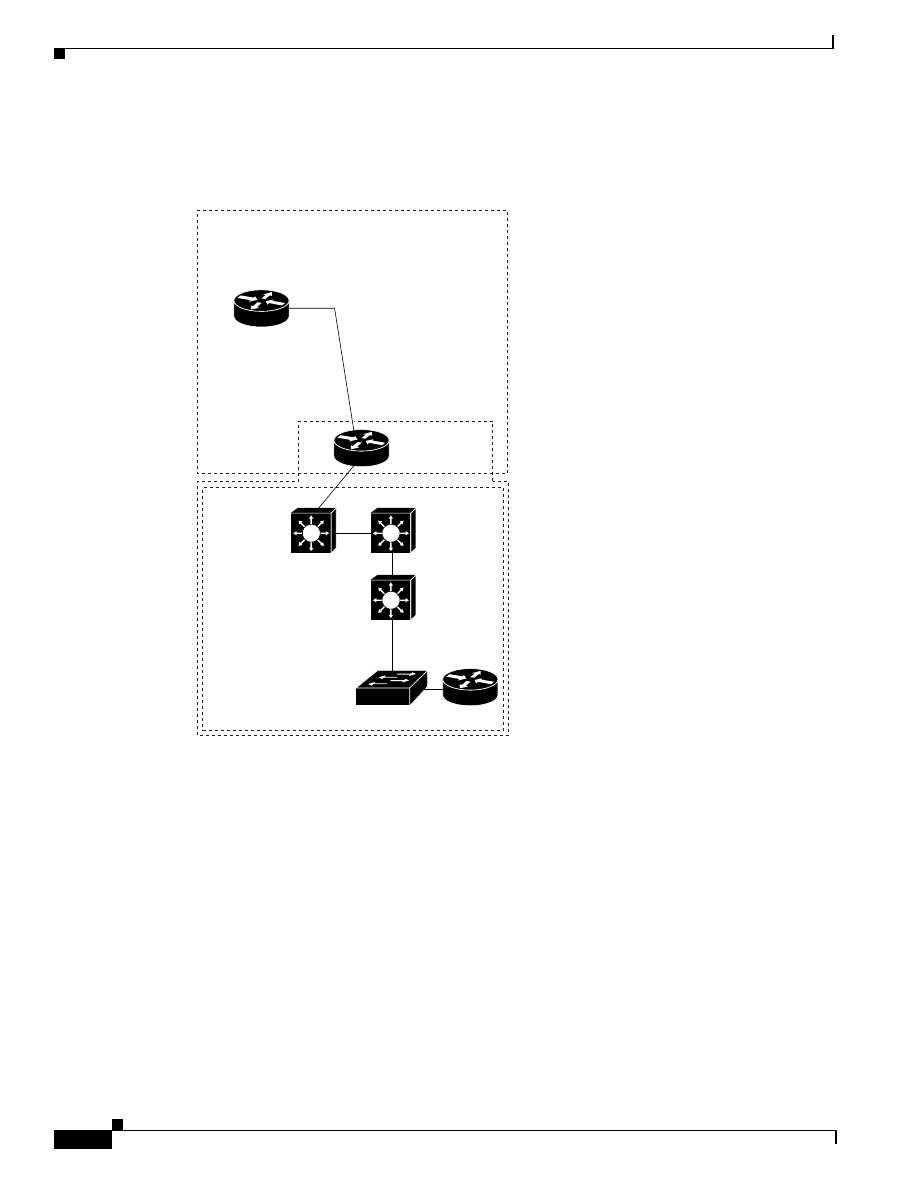
3-22
Quality of Service for Voice over IP Solutions Guide
Version 1.0
Chapter 3
Providing Branch Office Site Users and Telecommuters VoIP Access to the Main Campus
Providing Medium Size Branch Office Users QoS for VoIP Access to the Main Campus Using T1 Links
This portion of the configuration focuses on the path segment from the 3640 router to 7206 router.
Figure 3-4 shows the full path through the campus to the PBX interconnect 5300 router.
Figure 3-4
Path Between a Medium Branch Office Router and Campus Access Over a T1 PPP Link
Configuring QoS for VoIP on a T1 PPP Link
This section describes the configuration for deploying the following QoS for VoIP features for the T1
PPP link:
•
Compressed Real-Time Protocol (CRTP)—Used to compress the large RTP header.
•
IP RTP Priority queueing (Also referred to as Priority Queueing-Weighted Fair Queueing
(PQWFQ))—This feature is used as the queueing mechanism to give voice traffic strict priority
service.
Example 3-4 shows the configuration commands for the 3640 router T1 PPP link with the commands
for the QoS features called out in boldface. The QoS for VoIP features are configured within a virtual
template called Virtual-Template1 which is applied to interface Serial10/1.
7206
T1-
PPP
3640
Branch
office
Medium-size branch offices
Campus
PBX
Interconnect
AS5300
Catalyst
85xx
Catalyst
85xx
Catalyst
85xx
Server Farm
Catalyst 5x00
27278

3-23
Quality of Service for Voice over IP Solutions Guide
Version 1.0
Chapter 3
Providing Branch Office Site Users and Telecommuters VoIP Access to the Main Campus
Providing Medium Size Branch Office Users QoS for VoIP Access to the Main Campus Using T1 Links
Example 3-4
T1 PPP Link Configuration with QoS for VoIP
interface Loopback 0
ip address 10.14.26.26 255.255.255.0
h323-gateway voip interface
h323-gateway voip id r1-3640a-gk.cisco.com ipaddr 10.12.254.3 1719
h323-gateway voip h323-id r1-2600@cisco.com
!
interface Serial0/1
bandwidth 15440
ip address 10.14.97.2 255.255.252
encapsulation PPP
ppp multilink
multilink-group 1
!
interface multilink 1
ip unnumbered Serial0/1
ip rtp header-compression iphc-format
ip tcp header-compression iphc-format
fair-queue 64 256 0
ppp multilink
ip rtp priority 16384 16384 48
Configuring a Multilink Interface with QoS for VoIP Features for a T1 PPP Link
This section describes the QoS features you configure for the PPP link.Most of these QoS features are
the same as those that you configure for a PPP 64-K link, a Frame Relay 64-K link, and a Frame Relay
T1 link. Therefore, instead of repeating conceptual information, these steps refer to the related 64-K
Frame Relay sections that fully cover background information for these features common to all
configurations.
Note
This configuration process provides two alternative ways of configuring strict priority
queueing for VoIP traffic. In this set of steps, both methods are presented as Step 2. The
first Step 2 shows how to configure strict priority using IP RTP Priority. The second,
(alternative) Step 2 shows how to configure strict priority queueing using strict priority
within CBWFQ.
Step 1: Configure CRTP for the T1 PPP Link
To enable RTP header compression, perform the following task in interface configuration mode (you
need to enable compression on both ends of the connection):
For background information on CRTP, see “Step 1: Configure CRTP for a 64-K Frame Relay Link”
earlier in this chapter. Also, see Chapter 2, “About QoS Features for Voice.”
Command
Purpose
ip rtp header-compression iphc-format Enables RTP header compression for VoIP packets.

3-24
Quality of Service for Voice over IP Solutions Guide
Version 1.0
Chapter 3
Providing Branch Office Site Users and Telecommuters VoIP Access to the Main Campus
Providing Medium Size Branch Office Users QoS for VoIP Access to the Main Campus Using T1 Links
Step 2: Configure WFQ and Enable the Strict Priority Queue for VoIP Packets on the T1 PPP Link
When WFQ is enabled, it creates a strict priority queue that exists potentially for use by delay-sensitive
traffic such as voice traffic. However, the strict priority queue cannot be used until it is enabled through
configuration of the ip rtp priority command. This section gives the command syntax for the
fair-queue and ip rtp priority commands that you use to enable WFQ and its strict priority queue.
To enable weighted fair queueing for the PPP interface shown in Example 3-4, set the congestion
threshold after which messages for high-bandwidth conversations are dropped, and specify the number
of dynamic and reservable queues, perform the following task in interface configuration mode after
specifying the interface:
To reserve a strict priority queue for a set of RTP voice packet flows belonging to a range of UDP
destination ports, use the following command in interface configuration mode:
For background information on WFQ and the strict priority feature, see the “Step 2: Configure WFQ
and Enable the Strict Priority Queue for VoIP Packets on the PPP Link” earlier in this chapter. Also, see
Chapter 2, “About QoS Features for Voice.”
Step 2: Alternative Configuration: Configure WFQ and Enable the Strict Priority Queue within CBWFQ
This step provides an alternative method of giving voice traffic strict priority queueing. It describes how
you can use the same feature described in the first Step 2, but within CBWFQ to apply strict priority
queueing to a CBWFQ class used for voice traffic.
Command
Purpose
fair-queue 64 256 0
Configures the PPP interface to use weighted fair queueing
with a congestive discard threshold of 64, 256 dynamic
queues, and no reservable queues.
Command
Purpose
ip rtp priority 16384 16383 288
Reserves a strict priority queue for the VoIP packet flow
using destination ports in the range of 16384 and 16383.
VoIP flows for the example PPP link whose UDP
destination ports are within the range of 16384 and 16383
are granted strict priority with a bandwidth guarantee of
48 kbps.
The example configuration is designed to service 4 voice
calls at the cost of 12 kbps per call. For your configuration,
assume that each call consumes 12 K and set the bandwidth
parameter to the result of the following equation:
bandwidth
= 12 K x
number-of-calls
The IP RTP Priority feature does not require that you know
the port of a voice call. Rather, the feature gives you the
ability to identify a range of ports whose traffic is put into
the priority queue. Moreover, you can specify the entire
voice port range—16384 to 32767—to ensure that all voice
traffic is given strict priority service.

3-25
Quality of Service for Voice over IP Solutions Guide
Version 1.0
Chapter 3
Providing Branch Office Site Users and Telecommuters VoIP Access to the Main Campus
Providing Medium Size Branch Office Users QoS for VoIP Access to the Main Campus Using T1 Links
Priority queueing within CBWFQ enables use of the strict priority queue implicit to WFQ. Although it
is possible to enqueue various types of real-time traffic to the strict priority queue, it is strongly
recommended that you direct only voice traffic to it. This recommendation is made because voice traffic
is well-behaved, whereas other types of real-time traffic are not. Moreover, voice traffic requires that
delay be nonvariable in order to avoid jitter. Real-time traffic such as video could introduce variation in
delay thereby thwarting the steadiness of delay required for successful voice traffic transmission. For
complete information the Priority Queueing within CBWFQ feature, see Chapter 2, “QoS Features for
Voice over IP.”
This section gives the command syntax for the fair-queue and ip rtp priority commands that you use
to enable WFQ and its strict priority queue.
To enable weighted fair queueing for the PPP interface shown in Example 3-4, set the congestion
threshold after which messages for high-bandwidth conversations are dropped, and specify the number
of dynamic and reservable queues, perform the following task in interface configuration mode after
specifying the interface:
To create a class for voice called “class voice” and configure that class as a strict priority class with a
bandwidth allocation of 288 kbps, use the following commands beginning in interface configuration
mode:
Outcome Measurements for a T1 PPP Link QoS for VoIP Configuration
To convey a sense of how application of QoS features affects the quality of voice transmission, this
section provides measurements that show a set of results produced when the following criteria, shown
in Table 3-5, vary:
•
QoS Feature Used. This column identifies which QoS features were configured so as to satisfy
voice traffic requirements and improve voice quality.
•
Concurrent TCP Data Traffic (noise level). This column identifies the amount of data traffic
transmitted on the same line as voice.
Command
Purpose
fair-queue 64 256 0
Configures the PPP interface to use weighted fair
queueing with a congestive discard threshold of
64, 256 dynamic queues, and no reservable
queues.
Command
Purpose
class-map voice
Creates a class and names it voice.
match access-group 102
Specifies that all traffic belonging to the
numbered access group 102 will belong to the
voice class.
policy-map voiceplus
Creates a policy map called voiceplus to be
applied to the interface.
class voice
Adds the class called voice to the policy map
voiceplus.
priority 288
Enables the strict priority queue for the class
called voice and sets the bandwidth for the voice
traffic to 288 kbps.

3-26
Quality of Service for Voice over IP Solutions Guide
Version 1.0
Chapter 3
Providing Branch Office Site Users and Telecommuters VoIP Access to the Main Campus
Providing Medium Size Branch Office Users QoS for VoIP Access to the Main Campus Using T1 Links
•
Number of Voice Calls. This column gives the throughput—the number of voice calls put through
for the test.
•
Average PSQM Score
Medium Branch to Campus Access Using a T1 Frame Relay Link
This section describes the link type, the QoS features for VoIP you should use for this type of link and
circumstance, and how to handle conditions you might encounter that could negatively affect voice
traffic.
About the Link Type and Configuration
The campus (corporate) network provides a T1 Frame Relay link for access to and from the medium
branch office and main campus. This link connects from the medium branch office 3640 router across
a T1 line to the IGX switch and on through to the T1 Frame Relay link. The T1 Frame Relay link gives
access to the campus through the 7206 router. Although not shown in the illustrations depicting this
scenario or path segment, connected to the medium branch office 3640 router is the branch office user
network.
The T1 link, which is high speed, requires with one exception the same QoS features used for the Frame
Relay slow-speed link described in the “Using a 64-K Frame Relay Link”earlier in this chapter. Because
the T1 line is high-speed, it is not necessary to fragment large data packets to interleave with voice
packets.
Figure 3-5 shows the path from the 3640 router at the medium branch office which connects across the
T1 line through the IGX switch to the 7206 campus access router, then into the main campus and out
through the 5300 router across the PSTN, giving voice access to all corporate users. The 3640 router at
the small branch office is configured as a VoIP gateway that allows for codec conversion (using G.729a)
of analog voice to packetized digital voice and back.
Table 3-6
Voice Call and Quality Measurements for T-1 PPP
QoS Feature
Used
Concurrent
TCP Data
Traffic
Number of
Voice
Calls
PSQM Score Average
Without QoS
(to establish
baseline)
none
1
1.86154
6
2.00987
12
2.21582
23
2.42247
WFQ
1967 kbps
723 pps
18% CPU
24 TCP
streams
6
2.75
12
3.13926
23
2.98119
CBWFQ
1967 kbps
723 pps
18% CPU
24 TCP
streams
6
1.86772
12
1.87503
23
1.90786
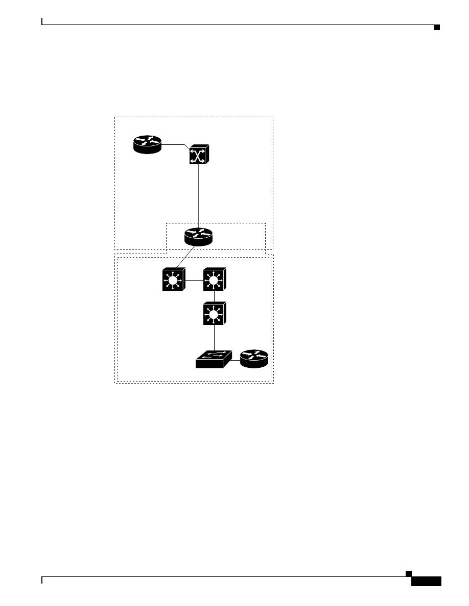
3-27
Quality of Service for Voice over IP Solutions Guide
Version 1.0
Chapter 3
Providing Branch Office Site Users and Telecommuters VoIP Access to the Main Campus
Providing Medium Size Branch Office Users QoS for VoIP Access to the Main Campus Using T1 Links
The main campus network contains Catalyst 8500 series switches with fast-speed (10-to-100 mbps
Ethernet) links. Traffic from multiple applications aggregates across the campus Ethernet links.
Figure 3-5
Path Between a Medium-Size Branch Office and the Main Campus Across
a T1 Frame Relay Link
Configuring QoS for VoIP on a T1 Frame Relay Link
This section describes the configuration for deploying the following QoS for VoIP features on the
outbound interface and at the PVC level for the T1 Frame Relay link:
•
Compressed Real-Time Protocol (CRTP)—Used to compress the large RTP header.
•
Frame Relay Traffic Shaping (FRTS)—Used to shape traffic leaving the 3640 router to meet the T1
Frame Relay link constraints in order to avoid packet loss and smooth out bursts.
•
IP RTP Priority queueing (Also referred to as Priority Queueing-Weighted Fair Queueing
(PQWFQ))—Is used as the queueing mechanism to give voice traffic strict priority service and
service data traffic with WFQ. (Alternatively, you could use the strict priority feature within
CBWFQ to give voice traffic the priority it requires.)
Example 3-5 shows the configuration commands for the 3640 router with the commands for the QoS
features called out in bold. In this example, subinterface Serial10/1.64 is configured for the Frame
Relay PVC.
T1>
Frame Relay
7206
IGX
3640
Branch
office
T1-
Frame
Relay
Medium-size branch offices
Campus
27277
PBX
Interconnect
Cisco AS5300
Catalyst
85xx
Catalyst
85xx
Catalyst
85xx
Server Farm
Catalyst 5x00

3-28
Quality of Service for Voice over IP Solutions Guide
Version 1.0
Chapter 3
Providing Branch Office Site Users and Telecommuters VoIP Access to the Main Campus
Providing Medium Size Branch Office Users QoS for VoIP Access to the Main Campus Using T1 Links
To register the router as a gateway with the gatekeeper, the router is configured with a loopback
interface. The loopback is used so that the gateway registration with the gatekeeper remains relatively
stable even if the gatekeeper cannot contact the gateway router when updating its tables.
The interfaces to the T1 Frame Relay link at the 3640 router in the medium branch office and the 7206
router at the campus access have mirroring configurations, using the same QoS features. Because they
are largely the same, this section describes the QoS configuration for the 3640 router only. CRTP and
FRTS must be enabled at the interface level. Though you enable FRTS at the interface level, you
configure it at the PVC level. At the PVC level, priority queueing configured through the
ip rtp priority
command, the Frame Relay CIR, the Frame Relay MINCIR, and WFQ parameters are configured; these
QoS features are configured within a Frame Relay map class called voice that is applied to the PVC.
Example 3-5
T1 Frame Relay Link Configuration with QoS for VoIP
interface Loopback 0
ip address 10.14.26.26.255.255.255.0
h323-gateway voip interface
h323-gateway voip id r1-3649a-gk.Cisco.com ipaddr 10.12.254.3 1719
h323-gateway voip h323-id r1-2600@Cisco.com
!
interface Serial0/1
no ip address
encapsulation frame-relay
ip rtp header-compression iphc-format
ip tcp header-compression iphc-format
frame-relay traffic-shaping
!
interface Serial0/1.64 point-to-point
ip address 10.14.97.2 255.255.255.252
frame-relay interface-dlci 64
frame-relay class voice
!
map-class frame-relay voice
frame-relay cir 1544000
frame-relay mincir 288
frame-relay fair-queue
ip rtp priority 16384 16383 288
Step 1: Configure CRTP for a T1 Link
For a VoIP network, compression reduces the bandwidth necessary for each voice call, thus increasing
the number of calls that can be transmitted over a given link.
The two portions—payload and header—of a voice packet can each be compressed. Payload
compression is determined by the codec used. CRTP is used to compress the RTP header. (CRTP
compression is applied to the voice packet header after its payload has already been reduced through
codec compression, which both converts analog to digital data and compresses the data.)
To compress the IP/UDP/RTP header down to as few as 2 bytes, you use CRTP. For a G.729 call, for
instance, this results in a cost of 12K—a cost that is acceptable to most users.
Before you can enable RTP header compression, you must have configured the Frame Relay line, as
shown previously in Example 3-5.

3-29
Quality of Service for Voice over IP Solutions Guide
Version 1.0
Chapter 3
Providing Branch Office Site Users and Telecommuters VoIP Access to the Main Campus
Providing Medium Size Branch Office Users QoS for VoIP Access to the Main Campus Using T1 Links
To enable RTP header compression, perform the following task in interface configuration mode (you
need to enable compression on both ends of the connection):
Step 2: Enable FRTS at the Interface Level for a FR T1 Link
FRTS shapes traffic to ensure that traffic conforms to the policies contracted for it. In the configuration
shown in Example 3-5, FRTS is enabled for interface Serial10/1 and configured for DLCI 64.
For the PVC, the Frame Relay CIR parameter—which specifies the upper bound on bandwidth
allocation—is set to the T1 link speed so that traffic will not burst above the link’s bandwidth causing
loss, which would degrade voice quality. Also for the PVC, the Frame Relay MINCIR—which
establishes the lower bound on bandwidth allocation—is set to the amount of bandwidth guaranteed to
be delivered to voice traffic under congestion conditions.
Note
You must set the bandwidth amount allocated for strict priority for voice to be less than or
equal to the MINCIR. (You use the
ip rtp priority
command within the map class for voice
to configure strict priority.)
The frame-relay fair-queue command is given to enable FRTS WFQ at the PVC level. WFQ is used
as the queueing mechanism for all traffic on this PVC other than voice. WFQ does not provide strict
priority required for voice. Therefore, to give voice traffic the strict priority queueing it requires, IP RTP
Priority is configured for the PVC. (For more information, see the “About IP RTP Priority” earlier in
this chapter.)
For more background information on use of FRTS for this step, see “Step 2: Enable FRTS at the
Interface Level for a 64-K Frame Relay Link” earlier in this chapter.
Enabling Frame Relay traffic shaping on an interface enables both traffic shaping and per-virtual circuit
queuing on all the interface’s PVCs and SVCs. Traffic shaping enables the router to control the circuit’s
output rate and react to congestion notification information if also configured.
To enable Frame Relay traffic shaping on the specified interface, complete the following task in
interface configuration mode:
Step 3: Configure a Map Class and Apply It to the PVC on a Frame Relay T1 Link
To configure a Frame Relay link for voice traffic, you must create a Frame Relay map class and
configure it to support voice traffic. The voice bandwidth, traffic shaping attributes, and strict priority
service for voice are configured on the map class. These attributes are required for sending voice traffic
on the PVC. The map class is applied to the Frame Relay DLCI used for voice traffic through the
frame-relay class voice command.
Command
Purpose
ip rtp header-compression
iphc-format
Enables RTP header compression for VoIP packets.
Command
Purpose
frame-relay traffic-shaping
Enables Frame Relay traffic shaping and per-virtual circuit
queuing.

3-30
Quality of Service for Voice over IP Solutions Guide
Version 1.0
Chapter 3
Providing Branch Office Site Users and Telecommuters VoIP Access to the Main Campus
Providing Medium Size Branch Office Users QoS for VoIP Access to the Main Campus Using T1 Links
To configure the frame-relay map class called voice, use the following commands:
Outcome Measurements for a T1 Frame Relay Link QoS for VoIP Configuration
To convey a sense of how application of QoS features affects the quality of voice transmission, this
section provides measurements that show a set of results produced when the following criteria, shown
in Table 3-7, vary:
•
QoS Feature Used. This column identifies which QoS features were configured so as to satisfy
voice traffic requirements and improve voice quality.
•
Concurrent TCP Data Traffic (noise level). This column identifies the amount of data traffic
transmitted on the same line as voice.
Command
Purpose
map-class frame-relay voice
Specifies the Frame Relay map class name—voice, in this
case—and enters map class configuration mode
frame-relay cir 154400
Specifies the committed information rate (CIR) in bits per
second (bps) for the PVC. For the example configuration,
the CIR is 1.544 bps.
frame-relay mincir 288
Specifies the minimum committed information rate
(MINCIR) (guaranteed for voice traffic under congestion
conditions) in bits per second (bps) for the PVC. For the
example configuration, the MINCIR is 288 bps.
frame-relay fair-queue
Enables weighted fair queuing for the map class. When
used in conjunction with WFQ, as in the example
configuration, IP RTP Priority provides strict priority to
voice traffic and WFQ scheduling among all other traffic.
(This command together with the ip rtp priority command
are also referred to as PQWFQ.)
ip rtp priority 16384 16383 288
Reserves a strict priority queue and bandwidth for the set
of RTP voice packet flows belonging to a range of UDP
destination ports.
For the example configuration, RTP (voice) packet flows
using ports in the range of 16384 and 16383 are granted
strict priority with a bandwidth guarantee of 288 kbps. The
example configuration is designed to service 24 voice calls
at the cost of 12 kbps per call. For your configuration,
assume that each call consumes 12 kbps and set the
bandwidth parameter to the result of the following
equation:
bandwidth
= 12 K x
number-of-calls
The IP RTP Priority feature does not require that you know
the port of a voice call. Rather, the feature gives you the
ability to identify a range of ports whose traffic is put into
the priority queue. Moreover, you can specify the entire
voice port range—16384 to 32767—to ensure that all voice
traffic is given strict priority service.
(This command together with the frame-relay fair-queue
command are also referred to as PQWFQ.)

3-31
Quality of Service for Voice over IP Solutions Guide
Version 1.0
Chapter 3
Providing Branch Office Site Users and Telecommuters VoIP Access to the Main Campus
Providing Medium Size Branch Office Users QoS for VoIP Access to the Main Campus Using T1 Links
•
Number of Voice Calls: This column gives the throughput—the number of voice calls put through
for the test.
•
Average PSQM Score.
Table 3-7
Voice Call and Quality Measurements for T-1 Frame Relay
QoS Feature
Used
Concurrent
TCP Data
Traffic
Number of
Voice
Calls
PSQM Score Average
PQWFQ
(Priority
Queueing within
CBWFQ)
none
6
2.4097
12
2.41582
23
2.4224
1967 kbps
723 pps
18% CPU
24 TCP
streams
6
2.46772
12
2.47503
23
2.50786

3-32
Quality of Service for Voice over IP Solutions Guide
Version 1.0
Chapter 3
Providing Branch Office Site Users and Telecommuters VoIP Access to the Main Campus
Providing Medium Size Branch Office Users QoS for VoIP Access to the Main Campus Using T1 Links
Wyszukiwarka
Podobne podstrony:
lab 7 solutions guide
(2002)Mobility management for VoIP service mobile IP vs SIP
2 Voip Practical Guide
Wicca Book of Spells and Witchcraft for Beginners The Guide of Shadows for Wiccans, Solitary Witche
Microsoft Dynamics CRM 2013 for Outlook Installing Guide
Comparison of Voice Activity Detection Algorithms for VoIP
Barret et al Templates For The Solution Of Linear Systems Building Blocks For Iterative Methods [s
Video 1200m METEL For new solutions
0415454972 Routledge Theory for Classics A Students Guide Adapted from Theory for Religious Studies
Herbs for Sports Performance, Energy and Recovery Guide to Optimal Sports Nutrition
NLP for Beginners An Idiot Proof Guide to Neuro Linguistic Programming
a practical guide on pharmacovigilance for beginners
06 User Guide for Artlantis Studio and Artlantis Render Export Add ons
Guide for Parameterization
A Guide for Counsellors Psychotherapists and Counselling
ESL Seminars Preparation Guide For The Test of Spoken Engl
więcej podobnych podstron