
ver . 2.0.3 15-10-2012
Manual
Adapter OBD v2
Software version:
NEVO-4.0.4.0
DiegoG3-3.0.8.0
Full compatibility with OBD Adapter v2 2.0B

Page 2 / 7
ver . 2.0.3 15-10-2012
●
●
●
●
●
●
●
●
1 Description
The OBD Adapter v2 enables communication between NEVO or Diego gas injection system
and petrol controller that uses OBDII diagnostic interface. The applications of this
communication are as following:
reading parameters form the OBDII system, and their visualization in the
NEVO/DiegoG3 application,
reading and controlling (including deleting) recorded and awaiting errors (trouble
codes) of the petrol controller,
automatic regulation and adaptation gas system on the basis of the corrections read
from OBD (see NEVO or DiegoG3 program instructions).
Adapter OBD v2 can work as a standalone device or it can be connected to the gas
installation from DiegoG3 or NEVO family.
When connected to NEVO or NEVO PLUS system Adapter OBDv2 requires NEVO-4.0.2.1 or
newer software.
When connected to DiegoG3 Adapter OBDv2requires DiegoG3 3.0.8.0 or newer software.
When Adapter OBDv2 is not connected to gas ECU it works as an OBD scanner and can be
communicated by NEVO 4.0.3.0 or newer software.
Details about usage of OBD Adapter v2 with KME gas systems are available in the
instructions for these systems. The use of Adapter with gas installation allows it to
automatically adjust and adapt the gas system, using the data read from the petrol ECU -
OBD adaptation (in the NEVO from version 4.0C, in DiegoG3 from version 30J). Adapter may
be also used for the time of calibration. In that case it is a tool facilitating the calibration, and
– to some extend – automatizing it. Adapter may also be installed in car permanently. In that
case it works as an interface between petrol and gas controllers and enables the gas
controller to introduce constant, adaptive correction.
The adapter may be connected to OBD using protocols that are applied in most cars
produced after year 2000:
ISO9141,
KWP2000slow,
KWP2000fast,
CAN_11bitID_500kbps,
CAN_29bitID_500kbps,
CAN_11bitID_250kbps,
CAN_29bitID_250kbps.
Page 3 / 7
ver . 2.0.3 15-10-2012
●
●
●
●
●
●
●
●
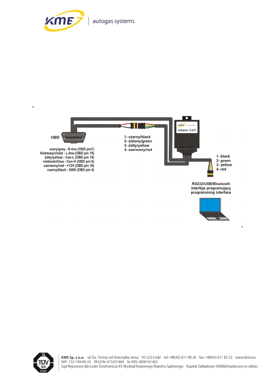
2 Installation
The adapter is designed to make its installation as easy as it is possible. The assembly
requires only connecting three plugs: two to the communication interface (one to the PC and
one to Diego), and one to OBD. Adapter is installed serially into the communication path
between PC computer and the controller and should be mounted inside the driver cabin,
which requires putting the communication wire through into the driver cabin. For the
convenience, extension cords to communication interface are added to the installation set.
The connection diagram for the standalone configuration is shown on the figure below.
If the gas controller has and old, non-hermetic standard of the communication plug, it needs
to be replaced by a plug in a new, hermetic standard (trade number: 239 000 033).
!!! WARNING: In cars with flap on the OBD connector, the flap should be removed before
connecting OBD module wires.
3 Operating the software
3.1
Software actualization
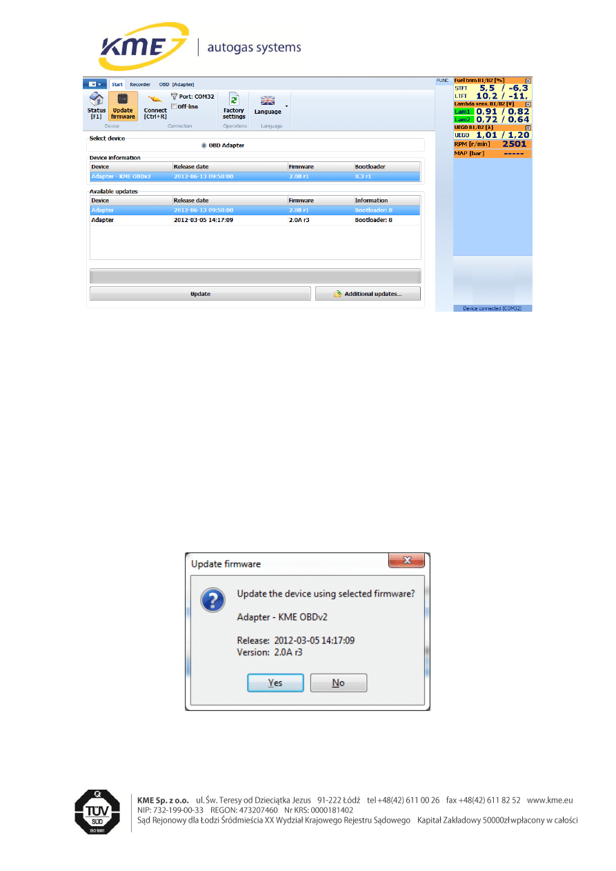
Updating the software changes the OBD Adapter v2 firmware and stores the device to
the factory settings of the loaded version. The current driver version and date of compilation
is shown in the frame. The box below displays a list of available updates.
Page 4 / 7
ver . 2.0.3 15-10-2012
●
●
●
●
●
●
●
●
Fig. 3.1 Firmware update window.
Procedure of updating is as follows:
o
If desired update file is not on the list of available updates press “Additional
updates...” button and choose file from your PC. It will be added to the list.
o
Choose update file and press “Update” button. First the window with
question about saving current settings to a file will appear. After saving or
choosing not to save the update confirmation window will appear (Fig. 3.2).
To start actualization process press “Yes”.
Fig. 3.2 Staring update confirmation window.
Page 5 / 7
ver . 2.0.3 15-10-2012
●
●
●
●
●
●
●
●
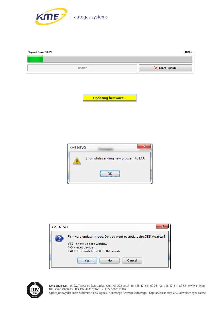
o
During actualization process progress the progress bar is shown (Fig. 3.3). Also
the status bar indicates execution of actualization process (Fig. 3.4).
Fig. 3.3 Actualization progress bar.
Fig. 3.4 Information about running actualization.
o
In case of fault in communication during actualization, (Fig. 3.5, press „OK”)
press “Auto connect”
Fig. 3.5 Information about communication failure.
Window shown on Fig. 3.6 appears after retrieving lost connection. Press “Ok” to
restart actualization process.
o
After finishing update, the program informs user about it.
Fig. 3.6 Window shown after communication failure during the actualization process.

Page 6 / 7
ver . 2.0.3 15-10-2012
●
●
●
●
●
●
●
●
3.2 OBD
tab
OBD tab element are divided into groups:
OBD Connection
o Protocol – is used to determine the protocol of the communication with the
OBD.
o Detect – enables to automatically detect the proper protocol.
o Connect – connects with the OBD using the chosen or the detected protocol.
o Disconnect – disconnects with OBD.
o Auto connect to OBD – when turned on, this option makes adapter to
automatically connect to the OBD after engine starts.
o State bar – indicates current OBD connection status.
OBD Scanner
o Live data – opens Live data window.
o Trouble codes – opens Trouble codes window.
o Read – reads trouble codes from petrol ECU.
o Clear – clears ECU trouble codes.
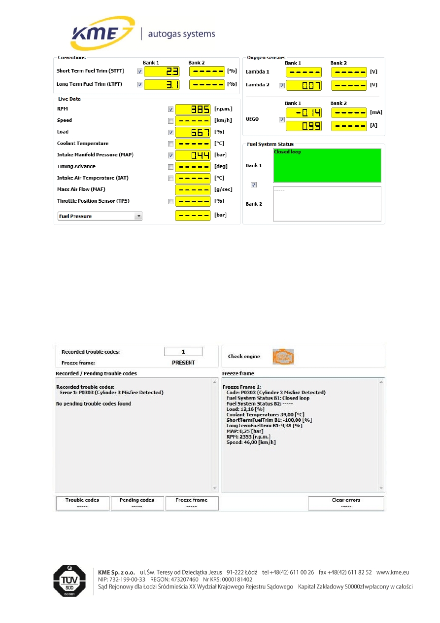
3.3
Live data window
Live Data tab provides functionality of controlling the readings from OBD. By every value
there is a check box, which turning on causes cyclic reading of the chosen value and
displaying it. If some values are not visible, they cannot be read from the OBD interface in
the particular car. Any value read from OBD can be displayed on the chart of the NEVO
system's recorder (Recorder tab).
Page 7 / 7
ver . 2.0.3 15-10-2012
●
●
●
●
●
●
●
●
Fig. 1 Live data window.
3.4
Trouble codes window
This tab provides functionality of monitoring, controlling and deleting recorded and awaiting
errors (trouble codes) of the petrol controller. To read recorded and awaiting trouble codes
press the Read button. To delete all trouble codes, the Clear button is used.
Fig. 2 Trouble codes window.
Wyszukiwarka
Podobne podstrony:
PL Adapter OBD v2 4 0 4 0 20B instrukcja
Sniffi v2 3 User Manual
EN AdapterOBD 10A 3 0 5 0
ASIO4ALL v2 Instruction Manual
ASIO4ALL v2 Instruction Manual
Manual Acer TravelMate 2430 US EN
CERBERUS P 6391 Manual EN
DEH P7400MP installation manual EN FR DE NL IT ESpdf
BlackBerry 8820 User Guide Manual (EN)
Ukł wytw en el z udziałem H2 ref v2
NMS KD 0017 en V01 03 N3000 IMC and ISC User Manual
Makita HP1640 EN Manual
Manual49 en
Bash Reference Manual [EN]
i9 user manual (en)
ASUS InstantFun Introduction XP EN V2
CERBERUS P 6382 1 Manual EN
Manual CF WS P XX en
więcej podobnych podstron