
PERIODICA POLYTECHNICA SER. EL. ENG. VOL. 43, NO. 2, PP. 91–
(1999)
ELECTRICAL DIMENSIONING OF
INVERTER-INDUCTOR-LOAD SYSTEM IN INDUCTION
HEATING OF FERROMAGNETIC PLATES AS LOAD
László K
OLLER
and György T
EVAN
Department of High Voltage Engineering and Equipment
Budapest University of Technology and Economics
H–1521 Budapest, Hungary
e-mail: koller@ntb.bme.hu
tel: (36-1-) 463-27-80
Received: Dec. 10, 1999
Abstract
An important practical field of induction heating is the heating of ferromagnetic plates. A significant
part of the heating arrangement is a medium-frequency – so called length-field – heating inductor. It is
supplied by a medium-frequency inverter of serial resonance circuit. The paper presents the detailed
dimensioning method of the inductor–load system, based on approximating analytical computations,
together with the interaction between that and the inverter. It gives the computed results for a concrete
situation.
Keywords: induction heating, heating of ferromagnetic plates, dimensioning inductors and inverters.
1. Introduction
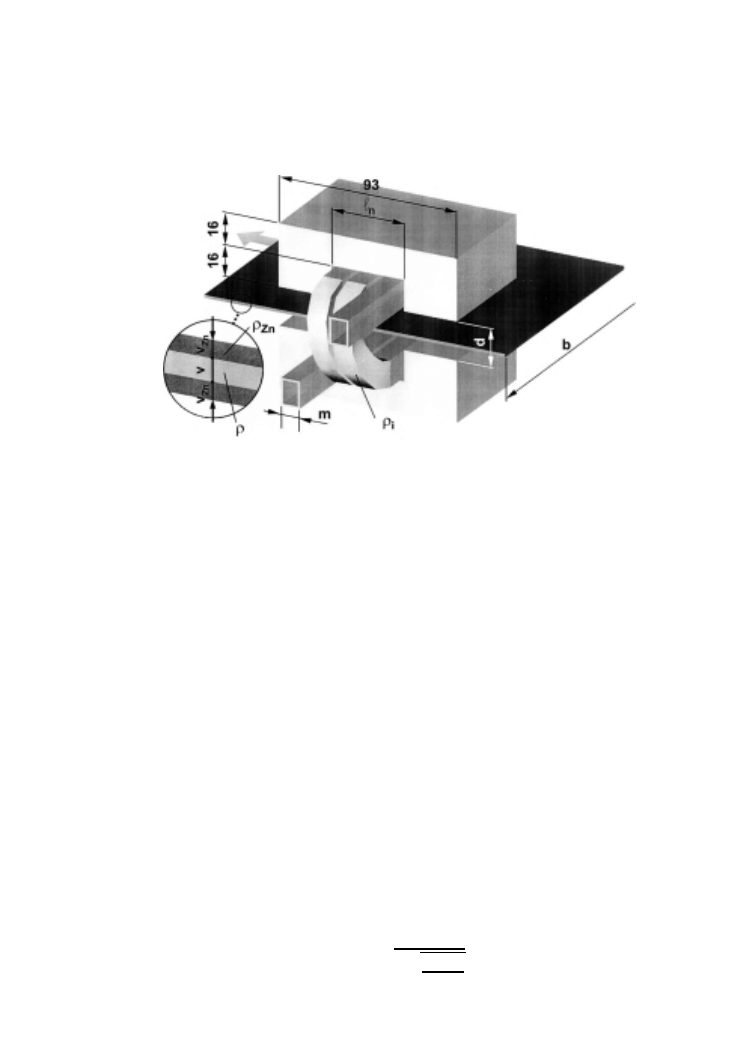
An important practical solution of the problem described in the title, the heating of
plastic covered steel plates, was dealt with by presentation (K
OLLER
and T
EVAN
,
1998). These are manufactured in such a way, that the zincous steel plates whose
temperature is increased to 120
. . . 200
◦
C, are covered by a plastic foil by a produc-
tion line, through which one or more band shape plates with a depth of 0
.5 . . . 1.0 mm
and a width of max. 1400 mm go at a speed of 3
. . . 5 m/s. The alternating magnetic
field excited by the length-field heating inductor (Fig.
) – parallel to the plane of
the band – induces eddy currents which heat the steel band. The computation of the
equivalent excitation length, which is necessary for the dimensioning, is detailed
in the paper (T
EVAN
and K
OLLER
, 1999). In this article the electromagnetic field
is determined between the ferromagnetic plate and the flux conductor – inductor
system with approximating analytical calculation of 2D-model. Then the power
is calculated, penetrated into the ferromagnetic plate and from this the equivalent
excitation length can be obtained with the condition that a uniform excitation of
equivalent length gives the same power.
92
L. KOLLER and GY. TEVAN
Fig. 1. Arrangement of length-field inductor
2. Dimensioning
During the dimensioning procedure the task is to induce power with the amplitude
and frequency defined by the technology in the ferromagnetic and moving band.
Nevertheless, this power can be generated only by the interaction of the serial
resonance circuit having a capacitance of C and the inductor-load system, therefore
not only the non-linear feature of the inductor-load system has to be taken into
consideration solving this complex dimensioning problem, but the operation of the
inverter, thus the fitting between these two components as well.
In case of the inductor only the distance between the pole surfaces, signed by
d and the number of turns, signed by N and in connection with it the width of the
conductor m are changeable. The current, flowing from the inverter through the
inductor and the capacitor, and the adjustable U
t
terminal voltage of the inverter have
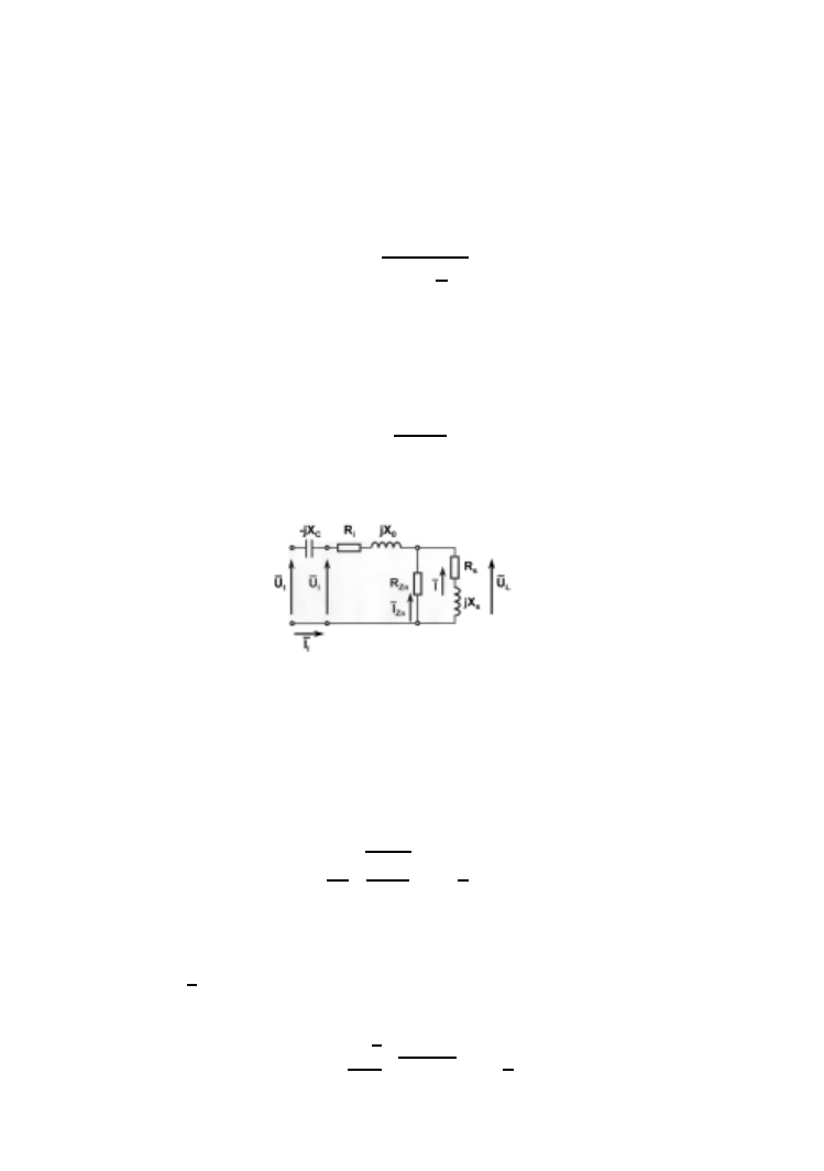
common zero point, which is set by the control system of the inverter. The equivalent
circuit, which is valid for the first harmonic can be seen in Fig.
. Disregarding
R
Z n
, there is the serial equivalent diagram of the inductor-load system between the
terminals of the inductor, signed by AB, where R
s
and X
s
are the AC resistance
and reactance of the steel layer(s) of the band(s) to be heated, at circular frequency
ω, concerning the output of the inverter,
R
i
= ρ
i
·
l
i
· N
m
2
· ρ
i
ω · µ
0
INVERTER-INDUCTOR-LOAD SYSTEM
93
symbolise the AC resistance of the coil with a length of l
i
,
X
0
= ω · µ
0
·
b
(d − z · v)
l
s
+
d
2
· N
2
is the reactance of the air gap, where z is the number of the plates.
The equivalent circuit does not contain the inner reactance of the coil, because
that is much smaller than X
0
. Based on the derivation published in the Appendix,
the effective AC resistance of the zinc layer(s),
R
Z n
= ρ
Z n
·
2
· b · z
l
· v
Z n
· N
2
is connected parallel to the impedance of the steel layer(s).
Fig. 2. Equivalent circuit
In the equivalent circuit R
s
and X
s
are current-dependent, because the plate
is ferromagnetic. According to the model (M
AC
L
EAN
, 1954) using step-function
magnetisation characteristics, in case of sinusoidal excitation and full wave absorp-
tion, the first harmonic field impedance can be written as follows (equation (240)
in book (T
EVAN
, 1985)):
Z
s
=
16
3
π
B
0
ωρ
2H
m
1
+
1
2
j
,
where B
0
is the 75 percentage of a pre-defined saturation induction (which depends
a bit on the excitation),
ρ is the resistivity of the plate and H
m
is the maximal value
of the sinusoidal magnetic field strength on the surface of the ferromagnetic plate,
so H
m
=
√
2H , here H is real, effective value. The effective value of the first
harmonic phazor of the electric field strength is:
E
= Z
s
· H =
8
4
√
2
3
π
B
0
ωρ H
1
+
1
2
j
.
94
L. KOLLER and GY. TEVAN
Based on the previous equation, the resultant load voltage of z pieces of band with
a width of b can be formulated:
U
L
= 2 · z · b · E · N =
16
·
4
√
2
3
· π
·
ρ · B
0
·
N
l
· ω · z · b · N ·
√
I
·
1
+
1
2
· j
, (1)
where I , the load current, flowing in the ferromagnetic part of the band exciting H is
also real, while l is the average equivalent excitation length (T
EVAN
and K
OLLER
,
1999), thus:
H
=
N
· I
l
.
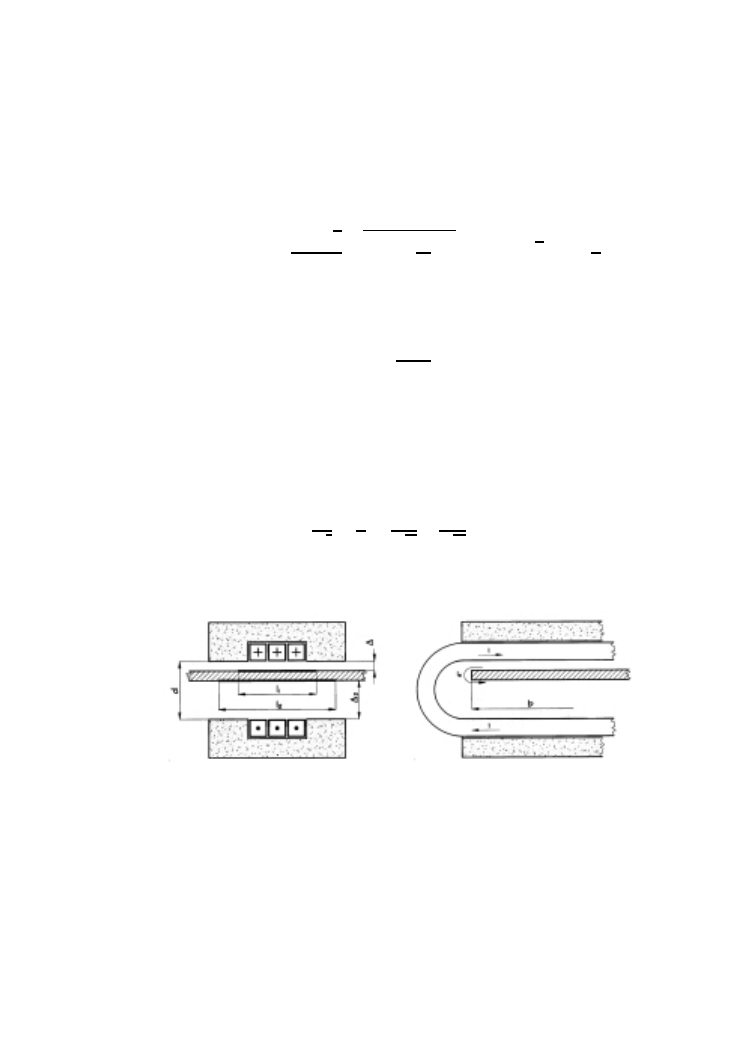
In case of one plate (z
= 1) – situating asymmetrically in the air gap – (Fig.
.a) the
equivalent excitation lengths are different on the two sides of the plate (
1
<
2
),
because the distances between these sides and the opposite pole surface are different
(
1
<
2
).
From Eq. (
) it can be seen, that voltage U
L
is inversely proportional to the
square root of average equivalent length
, therefore in this case that is determined
from Eq. (
1
√
l
=
1
2
·
1
√
l
1
+
1
√
l
2
.
(2)
The explanation of multiplier 2 in Eq. (
) is that there are eddy currents on both
sides of the plate, because of the both sides excitation (Fig.
.b).
Fig. 3. The equivalent excitation lengths when an asymmetrically positioned plate is heated
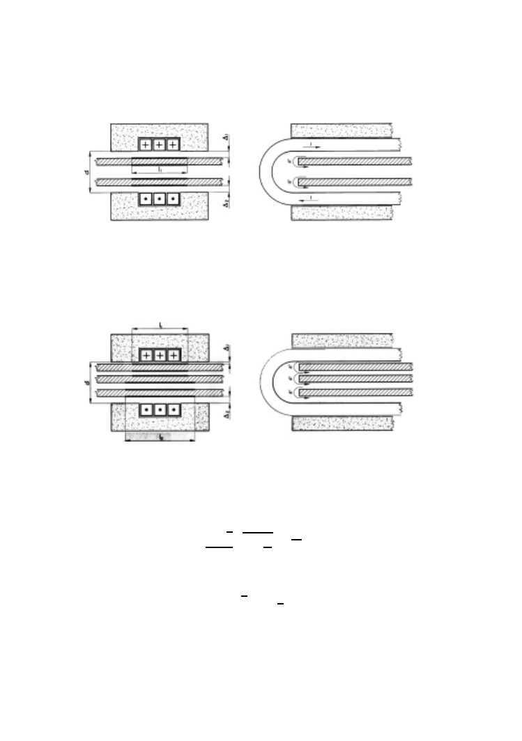
In case of two, symmetrically positioned plates (
1
=
2
)
=
1
=
2
(Fig.
.a). In Fig.
.b it can be observed that the eddy currents flow in opposite
direction close to the opposite plate surfaces.
In case of three or more asymmetrically positioned plates (Fig.
.a) the average
equivalent distance depends on the distance between the two plates, situating closest
to the pole surfaces, so formula (
) can be used in this case as well.
In Fig.
.b it can be seen that eddy currents flow in the plate in the middle,
because they are induced by the eddy currents flowing in the outside plates. Because
INVERTER-INDUCTOR-LOAD SYSTEM
95
Fig. 4. The equivalent excitation lengths in heating of two, symmetrically positioned plates
there are eddy currents flowing in each plate, therefore in Eq. (
) it was necessary
to use the number of the plates (z) as a multiplier.
Fig. 5. The equivalent excitation lengths in heating of three, asymmetrically positioned
plates
Introducing notation
K
=
16
4
√
2
3
π
ρ B
0
ω
l
N
√
N zb
,
(3)
the voltage phazor of the load:
U
L
= K
√
I
1
+
1
2
j
.
(4)
From Eqs. (
), it can be seen that the impedance of the steel layer is non-
linear, its features are different related to the other linear components of the equiv-
alent circuit (including the resistance of the zinc).
On the one hand, the value of the impedance depends on the value of the
current, namely it is inversely proportional to the square root of that. On the other

96
L. KOLLER and GY. TEVAN
hand, the impedance of the steel layer is directly proportional not to the square of
the number of turns, but to its power of 3/2.
According to Fig.
, the complex effective value of the inductor current is:
I
i
= I +
U
L
R
Z n
(5)
and the terminal voltage of the inverter:
U
t
= U
L
+ I
i
· (R
i
+ j · X
0
) − j · X
C
· I
i
.
By the substitution of (
), the terminal voltage can be given by the following formula:
U
t
= K
√
I
1
+
1
2
j
+ I
i
(R
i
+ j X
0
− j X
C
).
(6)
Based on the previously described equations and taking the control of the inverter
into consideration, the electrical parameters can be calculated.
2.1. Dimensioning by Assuming Sinusoidal Current
In case of serial resonance circuit inverter, to a first approximation, the current can
be considered to be sinusoidal. The control of the inverter ensures to be the zero
points of the current and square voltage of the inverter at the same time. It means
that the zero points of the first harmonic of the square voltage will be at the same
time like the previous ones. Therefore the first harmonic circular impedance has to
be purely effective resistance:
Im
U
t
I
i
= 0, where Im means the imaginary component.
Using formulae (
U
t
I
i
=
K
√
I
1
+
1
2
j
I
+
K
√
I
1
+
1
2
j
R
Z n
+ R
i
+ j (X
0
− X
C
) ≡ R
i
+ j (X
0
− X
C
)+
+
R
Z n
1
+
1
2
j
R
Z n
K
√
I
+ 1 +
1
2
j
≡ R
i
+ j (X
0
− X
C
) +
R
Z n
1
+
1
2
j
1
+
R
Z n
K
√
I
−
1
2
j
1
+
R
Z n
K
√
I
2
+
1
4
,
thus
0
= Im
U
t
I
i
= X
0
− X
C
+
R
2
Z n
2K
√
I
1
+
R
Z n
K
√
I
2
+
1
4
.

INVERTER-INDUCTOR-LOAD SYSTEM
97
From that the following quadratic equation can be written for
√
I :
(
√
I
)
2
−
K
2
(X
C
− X
0
)
−
2K
R
Z n
√
I
+
5K
2
4R
2
Z n
= 0;
(7)
by this I can be calculated. According to (
) K depends on
, the average equivalent
excitation length
depends on the excitation, which means that it depends on I ,
therefore determination of I requires iteration. Knowing I , U
L
can be calculated
from (
), I
i
from (
) and U
t
from (
). The other electrical parameters – like power,
voltage of the condenser, power coefficient and efficiency – can be determined based
on the equivalent circuit.
A computer program was developed for the dimensioning, which calculates
these electrical parameters at a given capacitance and by prescribing the inverter
voltage (according to the real operation) or prescribing the useful power.
2.2. More Accurate Dimensioning
In reality the current of the serial resonance circuit is not sinusoidal, but – in steady
state – it is a series of oscillations damping during a half of a period, whose circular
frequency is well known:
ω =
1
LC
−
R
2
4L
2
;
here L, R and C are the inductance, resistance and capacitance of the circuit.
(Since by inverter of resonance circuit the process has to be periodical, therefore
1
LC
>
R
2
4L
2
, so
L
C
>
R
2
is valid.) The terminal square voltage of the inverter has
the same circular frequency, so its first harmonic has it as well. According to that,
the capacitive phase angle is
tan
ψ =
1
C
ω
− Lω
R
=
1
− LCω
2
RC
ω
=
1
− LC
1
LC
−
R
2
4L
2
RC
ω
=
R
4L
ω
,
thus
tan
ψ =
1
4 tan
ϕ
,
(8)
where
ϕ is the phase angle of the inductor-load system at circular frequency ω. As
the computed tan
ψ was positive, it means that the first harmonic of the current
is ahead of the first harmonic of the voltage, so it reaches the zero point before
the commutation times. The computation is traced back to the
ψ = 0 situation in
such a way that the condenser with capacitance C is supposed to be two condensers
connected serially, so
1
C
=
1
C
0
+
1
C
1
,
(9)
98
L. KOLLER and GY. TEVAN
and the capacitance C
0
of the first condenser is chosen so that if it is connected in
the circuit only, then
ψ = 0. Therefore the following can be written:
1
C
0
ω
= Lω.
(10)
On the other hand,
1
C
ω
− Lω = R tan ψ,
based on this and from Eq. (
1
C
ω
= Lω + R tan ψ = R(tan ϕ + tan ψ) = R
tan
ϕ +
1
4 tan
ϕ
,
dividing it by Eq. (
), the result is:
C
0
C
=
R
L
ω
tan
ϕ +
1
4 tan
ϕ
= 1 +
1
4 tan
2
ϕ
.
(11)
However, tan
ϕ depends on that ω, which is determined by C
0
and the program
part calculating with
ψ = 0. Therefore the program has to be completed by an
additional iteration cycle.
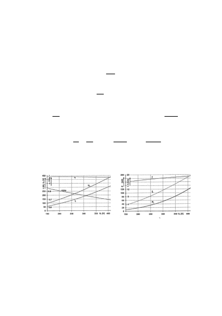
Fig. 6. Dimensioning results (
ψ = 0)
3. Results
Here the dimensioning can be presented for only one situation (d
= 2 mm; N = 3;
m
= 11 mm; ρ
i
= 2 · 10
−8
m; v = 0.5 mm; ρ = 2 · 10
−7
m, v
zn
= 7.1 µm,
ρ
Z n
= 1 · 10
−7
m; b = 1250 mm, ξ = 9 − 9 mm; z = 2; C = 6µF). The
parameters were represented on diagrams in Fig.
.a and
.b at
ψ = 0 as a function
of U
t
in full wave absorption domain. In Fig.
.a the current I
i
, the condenser
voltage U
C
, the efficiency of the inductor-load system signed by
η and the power
INVERTER-INDUCTOR-LOAD SYSTEM
99
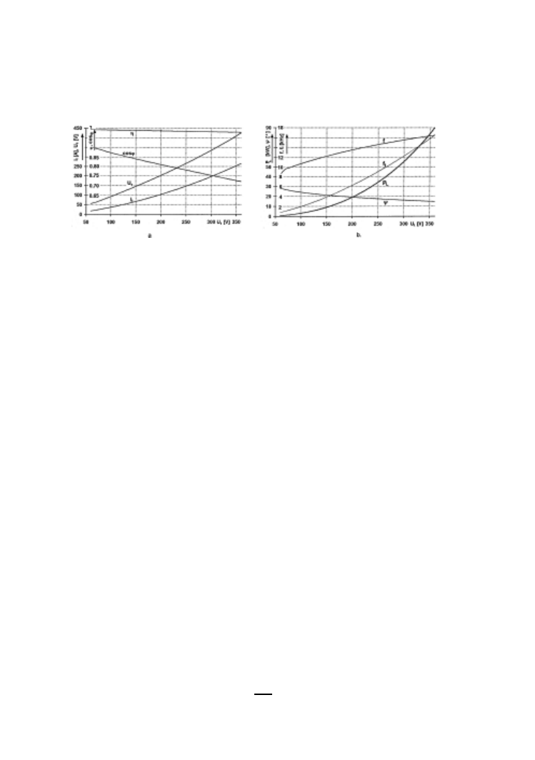
Fig. 7. More accurate dimensioning results
coefficient cos
ϕ can be seen, while in Fig.
.b the power P
L
, the actual frequency
f , and the frequency belonging to the full wave absorption as a borderline case, f
l
can be observed. The ideal heating for the technology is at U
t
= 405 V inverter
voltage, where f
= f
l
= 19.2 kHz and P
L
= 120 kW. The same diagrams are
presented for
ψ = 0 as well (Fig.
.a and
.b). In this case the ‘ideal’ parameters
are as follows: U
t
= 358 V, f = f
l
= 16.46 kHz; P
L
= 90 kW.
References
[1] K
OLLER
, L. – T
EVAN
, G
Y
.: Anwendung der Induktionserwärmung unter dem Curie-Punkt
für Produzierung von Stahlblechen mit Kunststoffbezug. 43. Internationales Wissenschaftliches
Kolloquium. TU Ilmenau 1998. Band 4.(1998) pp. 743–748.
[2] M
AC
L
EAN
, W. (1954): Theory of Strong Electromagnetic Waves in Massive Iron. Journal of
Applied Physics. New York N. Y. 25 Oct. 1954. pp. 1267–1270.
[3] T
EVAN
, G
Y
.: Áramkiszorítási modellek az er˝osáramú elektrotechnikában. (Current displace-
ment models in Power Engineering) Budapesti M˝uszaki Egyetem Mérnöki Továbbkép˝o Intézet.
Budapest. 1985 (in Hungarian).
[4] T
EVAN
, G
Y
. – K
OLLER
, L.: Approximate Calculation of Equivalent Excitation Length in In-
duction Heating with Flux Conductor Containing Ferromagnetic Plate. Periodica Polytechnica
43 No. 2, Budapest 1999. pp. 81–89.
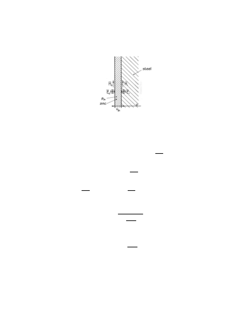
Appendix
Taking the Zinc Layer on the Steel Plate into Consideration
The zinc layer is very thin on the surface of the plate (on each side). Therefore the
phazor of the current density and in connection with it the phazor of the electrical
field strength is constant inside this layer (Fig.
). Thus, using the notation of the
figure E
1
∼
= E
0
and the current density inside the zinc layer is:
J
=
E
0
ρ
Z n
,
100
L. KOLLER and GY. TEVAN
Fig. F1. Field quantities on the surface of a thin zinc layer
where
ρ
Z n
is the resistivity of the zinc. Based on the excitation law
H
(H
0
− H
1
) =
H
v
Z n
J
=
H
v
Z n
E
0
ρ
Z n
,
so
H
0
= H
1
+
v
Z n
ρ
Z n
E
0
.
But
H
0
=
N I
i
,
H
1
= H =
N I
;
E
0
2bz N
= U
C
,
and substituting these relations into the previous equation, it can be written:
I
i
= I
U
c
ρ
Z n
2bz
v
Z n
N
2
,
so the resistance connecting parallel
R
Z n
= ρ
Z n
2bz
v
Z n
N
2
.
Document Outline
Wyszukiwarka
Podobne podstrony:
VHDL AMS Modeling of an Electric Power Steering System in a
VHDL AMS Modeling of an Electric Power Steering System in a
DIMENSIONS OF INTEGRATION MIGRANT YOUTH IN POLAND
DIMENSIONS OF INTEGRATION MIGRANT YOUTH IN POLAND
The Development of the Case System in French
Fraessdorf Quantization of Singular Systems in Canonical Formalism
US Patent 487,796 System Of Electrical Transmission Of Power
DIMENSIONS OF INTEGRATION MIGRANT YOUTH IN POLAND
Optimal Control of Three Phase PWM Inverter for UPS Systems
Comparision of expression systems in the yeast
British Patent 2,812 Improvements in Methods of and Apparatus for the Generation of Electric Current
Canadian Patent 29,537 Improvements in Methods of and Apparatus for the Electrical Transmission of P
alcatel support document for cable system in cuba
[Strizenec] DIMENSIONS OF SPIRITUALITY [paper]
Język angielski Political System In The UK
A neural network based space vector PWM controller for a three level voltage fed inverter induction
Zied H A A modular IGBT converter system for high frequency induction heating applications
Piórkowska K. Cohesion as the dimension of network and its determianants
więcej podobnych podstron