
BRITISH STANDARD
BS EN
1991-3:2006
Eurocode 1 — Actions
on structures —
Part 3: Actions induced by cranes and
machinery
The European Standard EN 1991-3:2006 has the status of a
British Standard
ICS 91.010.30
12&23<,1*:,7+287%6,3(50,66,21(;&(37$63(50,77('%<&23<5,*+7/$:
Licensed copy: BSI USER 06 Document Controller, Midmac Contracting Co. W.L.L, Version correct as of 14/10/2010
12:12, (c) BSI

BS EN 1991-3:2006
This British Standard was
published under the authority
of the Standards Policy and
Strategy Committee
on 29 September 2006
© BSI 2006
ISBN 0 580 48268 5
National foreword
This British Standard was published by BSI. It is the UK implementation of
EN 1991-3:2006.
The structural Eurocodes are divided into packages by grouping Eurocodes for
each of the main materials, concrete, steel, composite concrete and steel,
timber, masonry and aluminium, this is to enable a common date of
withdrawal (DOW) for all the relevant parts that are needed for a particular
design. The conflicting national standards will be withdrawn at the end of the
coexistence period, after all the EN Eurocodes of a package are available.
Following publication of the EN, there is a period allowed for national
calibration during which the national annex is issued, followed by a further
coexistence period of a maximum 3 years. During the coexistence period
Member States will be encouraged to adapt their national provisions to
withdraw conflicting national rules before the end of the coexistent period
in March 2010.
At the end of this coexistence period, the national standard(s) will be
withdrawn.
In the UK, the following national standards are superseded by the Eurocode 1
series. These standards will be withdrawn on a date to be announced.
Eurocode
Superseded British Standards
EN 1991-1-1
BS 6399-1:1996
EN 1991-1-2
none
EN 1991-1-3
BS 6399-3:1988
EN 1991-1-4
BS 6933-2:1997, BS 5400-2:1978*
EN 1991-1-5
BS 5400-2:1978*
EN 1991-1-6
none
EN 1991-1-7
none
EN 1991-2
BS 5400-1:1988, BS 5400-2:1978*
EN 1991-3
none
EN 1991-4
none
* N.B. BS 5400-2:1978 will not be fully superseded until publication of
Annex A.2 to BS EN 1990:2002.
The UK participation in its preparation was entrusted by Technical Committee
B/525, Building and civil engineering structures, to Subcommittee B/525/1,
Actions (loadings) on structures.
A list of organizations represented on B/525/1 can be obtained on request to its
secretary.
Where a normative part of this EN allows for a choice to be made at the
national level, the range and possible choice will be given in the normative text,
and a note will qualify it as a Nationally Determined Parameter (NDP). NDPs
can be a specific value for a factor, a specific level or class, a particular method
or a particular application rule if several are proposed in the EN.
Amendments issued since publication
Amd. No.
Date
Comments
Licensed copy: BSI USER 06 Document Controller, Midmac Contracting Co. W.L.L, Version correct as of 14/10/2010
12:12, (c) BSI

BS EN 1991-3:2006
© BSI 2006
i
To enable EN 1991-3 to be used in the UK, the NDPs will be published in a
National Annex, which will be made available by BSI in due course, after public
consultation has taken place.
This publication does not purport to include all the necessary provisions of a
contract. Users are responsible for its correct application.
Compliance with a British Standard cannot confer immunity from legal
obligations.
Summary of pages
This document comprises a front cover, an inside front cover, page i, a blank
page, the EN title page, pages 2 to 46, an inside back cover and a back cover.
The BSI copyright notice displayed in this document indicates when the
document was last issued.
Licensed copy: BSI USER 06 Document Controller, Midmac Contracting Co. W.L.L, Version correct as of 14/10/2010
12:12, (c) BSI

blank
Licensed copy: BSI USER 06 Document Controller, Midmac Contracting Co. W.L.L, Version correct as of 14/10/2010
12:12, (c) BSI

EUROPEAN STANDARD
NORME EUROPÉENNE
EUROPÄISCHE NORM
EN 1991-3
July 2006
ICS 91.010.30
Supersedes ENV 1991-5:1998
English Version
Eurocode 1 - Actions on structures - Part 3: Actions induced by
cranes and machinery
Eurocode 1 - Actions sur les structures - Partie 3: Actions
induites par les appareils de levage et les machines
Eurocode 1 - Einwirkungen auf Tragwerke - Teil 3:
Einwirkungen infolge von Kranen und Maschinen
This European Standard was approved by CEN on 9 January 2006.
CEN members are bound to comply with the CEN/CENELEC Internal Regulations which stipulate the conditions for giving this European
Standard the status of a national standard without any alteration. Up-to-date lists and bibliographical references concerning such national
standards may be obtained on application to the Central Secretariat or to any CEN member.
This European Standard exists in three official versions (English, French, German). A version in any other language made by translation
under the responsibility of a CEN member into its own language and notified to the Central Secretariat has the same status as the official
versions.
CEN members are the national standards bodies of Austria, Belgium, Cyprus, Czech Republic, Denmark, Estonia, Finland, France,
Germany, Greece, Hungary, Iceland, Ireland, Italy, Latvia, Lithuania, Luxembourg, Malta, Netherlands, Norway, Poland, Portugal, Romania,
Slovakia, Slovenia, Spain, Sweden, Switzerland and United Kingdom.
EUROPEAN COMMITTEE FOR STANDARDIZATION
C O M I T É E U R O P É E N D E N O R M A L I S A T I O N
E U R O P Ä I S C H E S K O M I T E E F Ü R N O R M U N G
Management Centre: rue de Stassart, 36 B-1050 Brussels
© 2006 CEN
All rights of exploitation in any form and by any means reserved
worldwide for CEN national Members.
Ref. No. EN 1991-3:2006: E
Licensed copy: BSI USER 06 Document Controller, Midmac Contracting Co. W.L.L, Version correct as of 14/10/2010
12:12, (c) BSI

EN 1991-3:2006 (E)
page 2
CONTENTS
Page
FOREWORD............................................................................................................................... 4
B
ACKGROUND OF THE
E
UROCODE PROGRAMME
....................................................................... 4
S
TATUS AND FIELD OF APPLICATION OF
E
UROCODES
................................................................ 5
N
ATIONAL
S
TANDARDS IMPLEMENTING
E
UROCODES
............................................................... 6
L
INKS BETWEEN
E
UROCODES AND HARMONISED TECHNICAL SPECIFICATIONS
(EN
S AND
ETA
S
)
FOR PRODUCTS
............................................................................................................... 6
A
DDITIONAL INFORMATION SPECIFIC FOR
EN
1991-3............................................................... 6
N
ATIONAL ANNEX FOR
EN
1991-3 ............................................................................................ 7
SECTION 1 GENERAL ............................................................................................................. 8
1.1
S
COPE
................................................................................................................................... 8
1.2
N
ORMATIVE
R
EFERENCES
................................................................................................... 8
1.3
D
ISTINCTION BETWEEN
P
RINCIPLES AND
A
PPLICATION
R
ULES
.......................................... 8
1.4
T
ERMS AND DEFINITIONS
..................................................................................................... 9
1.4.1
Terms and definitions specifically for hoists and cranes on runway beams........... 9
1.4.2
Terms and definitions specifically for actions induced by machines.................... 11
1.5
S
YMBOLS
........................................................................................................................... 12
SECTION 2
ACTIONS INDUCED BY HOISTS AND CRANES ON RUNWAY
BEAMS
14
2.1
F
IELD OF APPLICATION
................................................................................................. 14
2.2
C
LASSIFICATIONS OF ACTIONS
..................................................................................... 14
2.2.1
General.................................................................................................................. 14
2.2.2
Variable actions ................................................................................................... 14
2.2.3
Accidental actions ................................................................................................ 15
2.3
D
ESIGN SITUATIONS
...................................................................................................... 16
2.4
R
EPRESENTATION OF CRANE ACTIONS
.......................................................................... 17
2.5
L
OAD ARRANGEMENTS
................................................................................................. 17
2.5.1 Monorail hoist blocks underslung from runway beams ............................................. 17
2.5.1.1 Vertical loads ...................................................................................................................................... 17
2.5.1.2
Horizontal forces .......................................................................................................................... 17
2.5.2 Overhead travelling cranes ........................................................................................ 17
2.5.2.1 Vertical loads ...................................................................................................................................... 17
2.5.2.2 Horizontal forces................................................................................................................................. 18
2.5.3 Multiple crane action.................................................................................................. 20
2.6
V
ERTICAL CRANE LOADS
-
CHARACTERISTIC VALUES
.................................................. 21
2.7
H
ORIZONTAL CRANE LOADS
-
CHARACTERISTIC VALUES
............................................ 23
2.7.1
General.................................................................................................................. 23
2.7.2
Longitudinal forces H
L,i
and transverse forces H
T,i
caused by acceleration and
deceleration of the crane ..................................................................................................... 23
2.7.3
Drive force K ......................................................................................................... 25
2.7.4
Horizontal forces H
S,i,j,k
and the guide force
S caused by skewing of the crane.. 26
2.8
T
EMPERATURE EFFECTS
............................................................................................... 30
2.9
L
OADS ON ACCESS WALKWAYS
,
STAIRS
,
PLATFORMS AND GUARD RAILS
................... 30
2.9.1
Vertical loads ........................................................................................................ 30
2.9.2
Horizontal loads .................................................................................................... 30
2.10
T
EST LOADS
.............................................................................................................. 30
2.11
A
CCIDENTAL ACTIONS
.............................................................................................. 31
2.11.1
Buffer forces H
B,1
related to crane movement...................................................... 31
2.11.2 Buffer forces H
B,2
related to movements of the crab ................................................ 32
2.11.3
Tilting forces ........................................................................................................ 32
Licensed copy: BSI USER 06 Document Controller, Midmac Contracting Co. W.L.L, Version correct as of 14/10/2010
12:12, (c) BSI

EN 1991-3:2006 (E)
page 3
2.12
F
ATIGUE LOADS
........................................................................................................ 32
2.12.1
Single crane action............................................................................................... 32
2.12.2
Stress range effects of multiple wheel or crane actions....................................... 35
SECTION 3
ACTIONS INDUCED BY MACHINERY .................................................... 36
3.1
F
IELD OF APPLICATION
................................................................................................. 36
3.2
C
LASSIFICATION OF ACTIONS
....................................................................................... 36
3.2.1
General.................................................................................................................. 36
3.2.2
Permanent actions................................................................................................ 36
3.2.3
Variable actions ................................................................................................... 37
3.2.4
Accidental actions ................................................................................................ 37
3.3
D
ESIGN SITUATIONS
..................................................................................................... 37
3.4
R
EPRESENTATION OF ACTIONS
..................................................................................... 37
3.4.1
Nature of the loads ............................................................................................... 37
3.4.2
Modelling of dynamic actions ............................................................................... 38
3.4.3
Modelling of the machinery-structure interaction ................................................ 38
3.5
C
HARACTERISTIC VALUES
............................................................................................ 39
3.6
S
ERVICEABILITY CRITERIA
........................................................................................... 41
ANNEX A (NORMATIVE)...................................................................................................... 43
BASIS OF DESIGN – SUPPLEMENTARY CLAUSES TO EN 1990 FOR RUNWAY
BEAMS LOADED BY CRANES ............................................................................................ 43
A.1
G
ENERAL
.................................................................................................................... 43
A.2
U
LTIMATE LIMIT STATES
.............................................................................................. 43
A.2.1
Combinations of actions....................................................................................... 43
A.2.2
Partial factors ....................................................................................................... 44
A.2.3
ψ
-factors for crane loads.......................................................................................... 44
A.3
S
ERVICEABILITY LIMIT STATES
.................................................................................... 45
A.3.1
Combinations of actions........................................................................................ 45
A.3.2
Partial factors ...................................................................................................... 45
A.3.3
ψ
-factors for crane actions.................................................................................. 45
A.4
F
ATIGUE
....................................................................................................................... 45
ANNEX B
(INFORMATIVE) ........................................................................................... 46
GUIDANCE FOR CRANE CLASSIFICATION FOR FATIGUE ...................................... 46
Licensed copy: BSI USER 06 Document Controller, Midmac Contracting Co. W.L.L, Version correct as of 14/10/2010
12:12, (c) BSI

EN 1991-3:2006 (E)
page 4
Foreword
This European Standard (EN 1991-3:2006) has been prepared by Technical
Committee
CEN/TC 250 “Structural Eurocodes”, the secretariat of which is held by BSI.
CEN/TC 250 is responsible for all Structural Eurocodes.
This European Standard supersedes ENV 1991-5:1998.
This European Standard shall be given the status of a national standard, either by
publication of an identical text or by endorsement, at the latest by October 2006, and
conflicting national standards shall be withdrawn at the latest by March 2010.
According to the CEN/CENELEC Internal Regulations, the national standards
organizations of the following countries are bound to implement this European
Standard: Austria, Belgium, Cyprus, Czech Republic, Denmark, Estonia, Finland,
France, Germany, Greece, Hungary, Iceland, Ireland, Italy, Latvia, Lithuania,
Luxembourg, Malta, Netherlands, Norway, Poland, Portugal, Romania, Slovakia, Slovenia,
Spain,
Sweden, Switzerland and the United Kingdom.
Background of the Eurocode programme
In 1975, the Commission of the European Community decided on an action programme
in the field of construction, based on article 95 of the Treaty. The objective of the
programme was the elimination of technical obstacles to trade and the harmonisation of
technical specifications.
Within this action programme, the Commission took the initiative to establish a set of
harmonised technical rules for the design of construction works which, in a first stage,
would serve as an alternative to the national rules in force in the Member States and,
ultimately, would replace them.
For fifteen years, the Commission, with the help of a Steering Committee with
Representatives of Member States, conducted the development of the Eurocodes
programme, which led to the first generation of European codes in the 1980s.
In 1989, the Commission and the Member States of the EU and EFTA decided, on the
basis of an agreement
1
between the Commission and CEN, to transfer the preparation
and the publication of the Eurocodes to the CEN through a series of Mandates, in order
to provide them with a future status of European Standard (EN). This links de facto the
Eurocodes with the provisions of all the Council’s Directives and/or Commission’s
Decisions dealing with European standards (e.g. the Council Directive 89/106/EEC on
construction products - CPD - and Council Directives 93/37/EEC, 92/50/EEC and
89/440/EEC on public works and services and equivalent EFTA Directives initiated in
pursuit of setting up the internal market).
1
Agreement between the Commission of the European Communities and the European Committee for Standardisation (CEN)
concerning the work on EUROCODES for the design of building and civil engineering works (BC/CEN/03/89).
Licensed copy: BSI USER 06 Document Controller, Midmac Contracting Co. W.L.L, Version correct as of 14/10/2010
12:12, (c) BSI

EN 1991-3:2006 (E)
page 5
The Structural Eurocode programme comprises the following standards generally
consisting of a number of Parts:
EN 1990
Eurocode :
Basis of Structural Design
EN 1991
Eurocode 1:
Actions on structures
EN 1992
Eurocode 2:
Design of concrete structures
EN 1993
Eurocode 3:
Design of steel structures
EN 1994
Eurocode 4:
Design of composite steel and concrete structures
EN 1995
Eurocode 5:
Design of timber structures
EN 1996
Eurocode 6:
Design of masonry structures
EN 1997
Eurocode 7:
Geotechnical design
EN 1998
Eurocode 8:
Design of structures for earthquake resistance
EN 1999
Eurocode 9:
Design of aluminium structures
Eurocode standards recognise the responsibility of regulatory authorities in each
Member State and have safeguarded their right to determine values related to regulatory
safety matters at national level where these continue to vary from State to State.
Status and field of application of Eurocodes
The Member States of the EU and EFTA recognise that Eurocodes serve as reference
documents for the following purposes:
– as a means to prove compliance of building and civil engineering works with the
essential requirements of Council Directive 89/106/EEC, particularly Essential
Requirement N°1 – Mechanical resistance and stability – and Essential Requirement
N°2 – Safety in case of fire ;
– as a basis for specifying contracts for construction works and related engineering
services ;
– as a framework for drawing up harmonised technical specifications for construction
products (ENs and ETAs)
The Eurocodes, as far as they concern the construction works themselves, have a direct
relationship with the Interpretative Documents
2
referred to in Article 12 of the CPD,
although they are of a different nature from harmonised product standards
3
. Therefore,
technical aspects arising from the Eurocodes work need to be adequately considered by
CEN Technical Committees and/or EOTA Working Groups working on product
2
According to Art. 3.3 of the CPD, the essential requirements (ERs) shall be given concrete form in interpretative documents for
the creation of the necessary links between the essential requirements and the mandates for harmonised ENs and ETAGs/ETAs.
3
According to Art. 12 of the CPD the interpretative documents shall :
a)
give concrete form to the essential requirements by harmonising the terminology and the technical bases and indicating classes or levels
for each requirement where necessary ;
b)
indicate methods of correlating these classes or levels of requirement with the technical specifications, e.g. methods of calculation and of
proof, technical rules for project design, etc. ;
c)
serve as a reference for the establishment of harmonised standards and guidelines for European technical approvals.
The Eurocodes, de facto, play a similar role in the field of the ER 1 and a part of ER 2.
Licensed copy: BSI USER 06 Document Controller, Midmac Contracting Co. W.L.L, Version correct as of 14/10/2010
12:12, (c) BSI

EN 1991-3:2006 (E)
page 6
standards with a view to achieving full compatibility of these technical specifications
with the Eurocodes.
The Eurocode standards provide common structural design rules for everyday use for
the design of whole structures and component products of both a traditional and an
innovative nature. Unusual forms of construction or design conditions are not
specifically covered and additional expert consideration will be required by the designer
in such cases.
National Standards implementing Eurocodes
The National Standards implementing Eurocodes will comprise the full text of the
Eurocode (including any annexes), as published by CEN, which may be preceded by a
National title page and National foreword, and may be followed by a National annex.
The National annex may only contain information on those parameters which are left
open in the Eurocode for national choice, known as Nationally Determined Parameters,
to be used for the design of buildings and civil engineering works to be constructed in
the country concerned, i.e. :
– values and/or classes where alternatives are given in the Eurocode,
– values to be used where a symbol only is given in the Eurocode,
– country specific data (geographical, climatic, etc.), e.g. snow map,
– the procedure to be used where alternative procedures are given in the Eurocode.
It may also contain:
– decisions on the application of informative annexes,
– references to non-contradictory complementary information to assist the user to
apply the Eurocode.
Links between Eurocodes and harmonised technical specifications (ENs and
ETAs) for products
There is a need for consistency between the harmonised technical specifications for
construction products and the technical rules for works
4
. Furthermore, all the
information accompanying the CE Marking of the construction products which refer to
Eurocodes should clearly mention which Nationally Determined Parameters have been
taken into account.
Additional information specific for EN 1991-3
EN 1991-3 gives design guidance and actions for the structural design of buildings and
civil engineering works, including the following aspects:
– actions induced by cranes, and
– actions induced by machinery.
EN 1991-3 is intended for clients, designers, contractors and public authorities.
4
see Art.3.3 and Art.12 of the CPD, as well as clauses 4.2,
4.3.1, 4.3.2 and 5.2 of ID 1
.
Licensed copy: BSI USER 06 Document Controller, Midmac Contracting Co. W.L.L, Version correct as of 14/10/2010
12:12, (c) BSI

EN 1991-3:2006 (E)
page 7
EN 1991-3 is intended to be used with EN 1990, the other Parts of EN 1991 and EN
1992 to EN 1999 for the design of structures.
National annex for EN 1991-3
This Standard gives alternative procedures, values and recommendations for classes
with notes indicating where national choices have to be made. Therefore the National
Standard implementing EN 1991-3 should have a National Annex containing all
Nationally Determined Parameters to be used for the design of members to be
constructed in the relevant country.
National choice is allowed in EN 1991-3 through the following paragraphs:
Paragraph
Item
2.1 (2)
Procedure when actions are given by the crane supplier
2.5.2.1 (2)
Eccentricity of wheel loads
2.5.3 (2)
Maximum number of cranes to be considered in the most
unfavourable position
2.7.3 (3)
Value of friction factor
A2.2 (1)
Definition of
γ
-values for cases STR and GEO
A2.2 (2)
Definition of
γ
-values for case EQU
A2.3 (1)
Definition of
ψ
-values
Licensed copy: BSI USER 06 Document Controller, Midmac Contracting Co. W.L.L, Version correct as of 14/10/2010
12:12, (c) BSI

EN 1991-3:2006 (E)
page 8
Section 1 General
1.1 Scope
(1) Part 3 of EN 1991 specifies imposed loads (models and representative values)
associated with cranes on runway beams and stationary machines which include, when
relevant, dynamic effects and braking, acceleration and accidental forces.
(2) Section 1 defines common definitions and notations.
(3) Section 2 specifies actions induced by cranes on runways.
(4) Section 3 specifies actions induced by stationary machines.
1.2 Normative References
This European Standard incorporates by dated or undated reference provisions from
other publications. These normative references are cited at the appropriate places in the
text and the publications are listed hereafter. For dated references, subsequent
amendments to, or revisions of, any of these publications apply to this European Stan-
dard only when incorporated in it by amendment or revision. For undated references the
latest edition of the publication referred to applies (including amendments).
ISO 3898 Basis of design of structures - Notations. General symbols
ISO 2394 General principles on reliability for structures
ISO 8930 General principles on reliability for structures. List of equivalent terms
EN 1990
Eurocode: Basis of Structural Design
EN 13001-1
Cranes – General design – Part 1: General principles and
requirements
EN 13001-2
Cranes – General design – Part 2: Load effects
EN 1993-1-9
Design of steel structures – Part 1-9: Fatigue
EN 1993-6
Design of steel structures – Part 6: Crane runway beams
1.3 Distinction between Principles and Application Rules
(1) Depending on the character of the individual clauses, distinction is made in this Part
of prEN 1991 between Principles and Application Rules.
(2) The Principles comprise:
– general statements and definitions for which there is no alternative, as well as
– requirements and analytical models for which no alternative is permitted unless
specifically stated.
(3) The Principles are identified by the letter P following the paragraph number.
Licensed copy: BSI USER 06 Document Controller, Midmac Contracting Co. W.L.L, Version correct as of 14/10/2010
12:12, (c) BSI

EN 1991-3:2006 (E)
page 9
(4) The Application Rules are generally recognised rules which comply with the
Principles and satisfy their requirements.
(5) It is permissible to use alternative design rules different from the Application Rules
given in EN 1991-3 for works, provided that it is shown that the alternative rules accord
with the relevant Principles and are at least equivalent with regard to the structural
safety, serviceability and durability that would be expected when using the Eurocodes.
NOTE: If an alternative design rule is substituted for an Application Rule, the resulting design
cannot be claimed to be wholly in accordance with EN 1991-3 although the design will remain in
accordance with the Principles of EN 1991-3. When EN 1991-3 is used in respect of a property
listed in an Annex Z of a product standard or an ETAG, the use of an alternative design rule may
not be acceptable for CE marking.
(6) In this Part the Application Rules are identified by a number in brackets, e.g. as this
clause.
1.4 Terms and definitions
For the purposes of this European Standard, the terms and definitions given in ISO
2394, ISO 3898, ISO 8930 and the following apply. Additionally for the purposes of this
standard a basic list of terms and definitions is provided in EN 1990, 1.5.
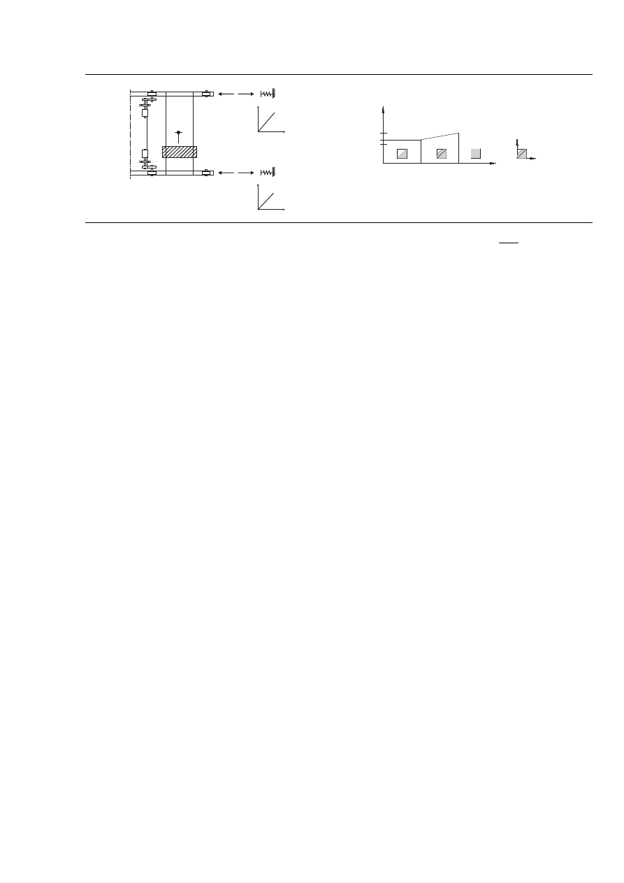
1.4.1 Terms and definitions specifically for hoists and cranes on runway beams
1.4.1.1
dynamic factor
factor that represents the ratio of the dynamic response to the static one
1.4.1.2
self-weight Q
c
of the crane
self-weight of all fixed and movable elements including the mechanical and electrical
equipment of a crane structure, however without the lifting attachment and a portion of
the suspended hoist ropes or chains moved by the crane structure, see 1.4.1.3
1.4.1.3
hoist load Q
h
load including the masses of the payload, the lifting attachment and a portion of the
suspended hoist ropes or chains moved by the crane structure, see Figure 1.1
Q
c
Q
h
Figure 1.1 — Definition of the hoist load and the self-weight of a crane
Licensed copy: BSI USER 06 Document Controller, Midmac Contracting Co. W.L.L, Version correct as of 14/10/2010
12:12, (c) BSI

EN 1991-3:2006 (E)
page 10
1.4.1.4
crab
part of an overhead travelling crane that incorporates a hoist and is able to travel on rails
on the top of the crane bridge
1.4.1.5
crane bridge
part of an overhead travelling crane that spans the crane runway beams and supports the
crab or hoist block
1.4.1.6
guidance means
system used to keep a crane aligned on a runway, through horizontal reactions between
the crane and the runway beams
NOTE The guidance means can consist of flanges on the crane wheels or a separate system of
guide rollers operating on the side of the crane rails or the side of the runway beams
1.4.1.7
hoist
machine for lifting loads
1.4.1.8
hoist block
underslung trolley that incorporates a hoist and is able to travel on the bottom flange of
a beam, either on a fixed runway (as shown in Figure 1.2) or under the bridge of an
overhead travelling crane (as shown in Figures 1.3 and 1.4)
1.4.1.9
monorail hoist block
hoist block that is supported on a fixed runway, see Figure 1.2
1.4.1.10
crane runway beam
beam along which an overhead travelling crane can move
1.4.1.11
overhead travelling crane
a machine for lifting and moving loads, that moves on wheels along overhead crane
runway beams. It incorporates one or more hoists mounted on crabs or underslung
trolleys
1.4.1.12
runway beam for hoist block
crane runway beam provided to support a monorail hoist block that is able to travel on
its bottom flange, see Figure 1.2
Licensed copy: BSI USER 06 Document Controller, Midmac Contracting Co. W.L.L, Version correct as of 14/10/2010
12:12, (c) BSI
EN 1991-3:2006 (E)
page 11
1
2
Key
1
Runway beam
2
Hoist block
Figure 1.2 — Runway beam with hoist block
1.4.1.13
underslung crane
overhead travelling crane that is supported on the bottom flanges of the crane runway
beams, see Figure 1.3
Figure 1.3 — Underslung crane with hoist block
1.4.1.14
top-mounted crane
overhead travelling crane that is supported on the top of the crane runway beam
NOTE It usually travels on rails, but sometimes travels directly on the top of the beams, see Figure
1.4
Figure 1.4 — Top mounted crane with hoist block
1.4.2 Terms and definitions specifically for actions induced by machines
1.4.2.1
natural frequency
frequency of free vibration on a system
NOTE For a multiple degree-of-freedom system, the natural frequencies are the frequencies of the
normal modes of vibrations
Licensed copy: BSI USER 06 Document Controller, Midmac Contracting Co. W.L.L, Version correct as of 14/10/2010
12:12, (c) BSI

EN 1991-3:2006 (E)
page 12
1.4.2.2
free vibration
vibration of a system that occurs in the absence of forced vibration
1.4.2.3
forced vibration
vibration of a system if the response is imposed by the excitation
1.4.2.4
damping
dissipation of energy with time or distance
1.4.2.5
resonance
resonance of a system in forced harmonic vibration exists when any change, however
small, in the frequency of excitation causes a decrease in the response of the system
1.4.2.6
mode of vibration
characteristic pattern assumed by a system undergoing vibration in which the motion of
every particle is simple harmonic with the same frequency
NOTE Two or more modes may exist concurrently in a multiple degree of freedom system. A
normal (natural) mode of vibration is a mode of vibration that is uncoupled from other modes of
vibration of a system
1.5 Symbols
(1) For the purposes of this European standard, the following symbols apply.
NOTE: The notation used is based on ISO 3898: 1997.
(2) A basic list of symbols is provided in EN 1990 clause 1.6 and the additional
notations below are specific to this part of EN 1991.
Latin upper case letters
F
ϕ,k
characteristic value of a crane action
F
k
characteristic static component of a crane action
Fs
free force of the rotor
F
w
*
forces caused by in-service wind
H
B,1
buffer forces related to movements of the crane
H
B,2
buffer forces related to movements of the crab
H
K
horizontal load for guard rails
H
L
longitudinal forces caused by acceleration and deceleration of the crane
H
S
horizontal forces caused by skewing of the crane
H
T,1;
H
T,2
transverse forces caused by acceleration and deceleration of the crane
H
T,3
transverse forces caused by acceleration and deceleration of the crab
H
TA
tilting force
K
drive force
Licensed copy: BSI USER 06 Document Controller, Midmac Contracting Co. W.L.L, Version correct as of 14/10/2010
12:12, (c) BSI

EN 1991-3:2006 (E)
page 13
M
k
(t)
circuit moment
Q
e
fatigue load
Q
c
self-weight of the crane
Q
h
hoist load
Q
T
test load
Q
r
wheel load
S
guide force
Latin lower case letters
b
r
width of rail head
e
eccentricity of wheel load
e
M
eccentricity of the rotor mass
h
distance between the instantaneous slide pole and means of guidance
kQ
load spectrum factor
ℓ
span of the crane bridge
m
c
mass of the crane
m
w
number of single wheel drives
m
r
mass of rotor
n
number of wheel pairs
n
r
number of runway beams
Greek lower case letters
α
skewing angle
ζ
damping ratio
η
ratio of the hoist load that remains when the payload is removed, but is not
included in the self-weight of the crane
λ
damage equivalent factor
s
λ
force factors
µ
friction factor
b
ξ
buffer characteristic
ϕ
dynamic factor
3
2
1
,
,
ϕ
ϕ
ϕ
7
6
5
4
,
,
,
ϕ
ϕ
ϕ
ϕ
dynamic factor applied to actions induced by cranes
fat
ϕ
damage equivalent dynamic impact factor
M
ϕ
dynamic factor applied to actions induced by machines
e
ω
natural frequency of the structure
r
ω
circular frequency of the rotor
s
ω
frequency of the exiting force
Licensed copy: BSI USER 06 Document Controller, Midmac Contracting Co. W.L.L, Version correct as of 14/10/2010
12:12, (c) BSI

EN 1991-3:2006 (E)
page 14
Section 2 Actions induced by hoists and cranes on runway beams
2.1 Field of application
(1) This section specifies actions (models and representative values) induced by:
– underslung trolleys on runways, see 2.5.1 and 2.5.2;
– overhead travelling cranes, see 2.5.3 and 2.5.4.
(2) The methods prescribed in this section are compatible with the provisions in EN
13001-1 and EN 13001-2, to facilitate the exchange of data with crane suppliers.
NOTE: Where the crane supplier is known at the time of design of the crane runway, more accurate
data may be applied for the individual project. The National Annex may give information on the
procedure.
2.2 Classifications of actions
2.2.1 General
(1)P Actions induced by cranes shall be classified as variable and accidental actions
which are represented by various models as described in 2.2.2 and 2.2.3.
2.2.2 Variable actions
(1) For normal service conditions variable crane actions result from variation in time
and location. They include gravity loads including hoist loads, inertial forces caused by
acceleration/deceleration and by skewing and other dynamic effects.
(2) The variable crane actions should be separated into:
– variable vertical crane actions caused by the self-weight of the crane and the hoist
load;
– variable horizontal crane actions caused by acceleration or deceleration or by
skewing or other dynamic effects.
(3) The various representative values of variable crane actions are characteristic values
composed of a static and a dynamic component.
(4) Dynamic components induced by vibration due to inertial and damping forces are in
general accounted by dynamic factors
ϕ
to be applied to the static action values.
k
i
k
F
F
ϕ
ϕ
=
,
(2.1)
where:
k
,
F
ϕ
is the characteristic value of a crane action;
i
ϕ
is the dynamic factor, see Table 2.1;
k
F
is the characteristic static component of a crane action.
(5) The various dynamic factors and their application are listed in Table 2.1.
Licensed copy: BSI USER 06 Document Controller, Midmac Contracting Co. W.L.L, Version correct as of 14/10/2010
12:12, (c) BSI

EN 1991-3:2006 (E)
page 15
(6) The simultaneity of the crane load components may be taken into account by
considering groups of loads as identified in Table 2.2. Each of these groups of loads
should be considered as defining one characteristic crane action for the combination
with non-crane loads.
NOTE: The grouping provides that only one horizontal crane action is considered at a time.
2.2.3 Accidental actions
(1) Cranes can generate accidental actions due to collision with buffers (buffer forces) or
collision of lifting attachments with obstacles (tilting forces). These actions should be
considered for the structural design where appropriate protection is not provided.
(2) Accidental actions described in 2.11 refer to common situations. They are
represented by various load models defining design values (i.e. to be used with
A
γ
= 1,0)
in the form of equivalent static loads.
(3) The simultaneity of accidental crane load components may be taken into account by
considering groups of loads as identified in Table 2.2. Each of these groups of loads
defines one crane action for the combination of non-crane loads.
Table 2.1 — Dynamic factors
i
ϕ
Dynamic
factors
Effects to be considered
To be applied to
1
ϕ
– excitation of the crane structure due
to lifting the hoist load off the ground
self-weight
of
the
crane
2
ϕ
or
3
ϕ
– dynamic effects of transferring the
hoist load from the ground to the
crane
– dynamic effects of sudden release of
the payload if for example grabs or
magnets are used
hoist load
4
ϕ
– dynamic effects induced when the
crane is travelling on rail tracks or
runways
self-weight
of
the
crane and hoist load
5
ϕ
– dynamic effects caused by drive
forces
drive forces
6
ϕ
– dynamic effects of a test load
moved by the drives in the way the
crane is used
test load
7
ϕ
– dynamic elastic effects of impact on
buffers
buffer loads
Licensed copy: BSI USER 06 Document Controller, Midmac Contracting Co. W.L.L, Version correct as of 14/10/2010
12:12, (c) BSI

EN 1991-3:2006 (E)
page 16
Table 2.2 — Groups of loads and dynamic factors to be
considered as one characteristic crane action
Groups of loads
Symbol Section
Ultimate Limit State
Test
load
Acci-
dental
1
2
3
4
5
6
7
8
9
10
1 Self-weight of crane
Q
c
2.6
1
ϕ
1
ϕ
1
4
ϕ
4
ϕ
4
ϕ
1
1
ϕ
1
1
2 Hoist load
Q
h
2.6
2
ϕ
3
ϕ
-
4
ϕ
4
ϕ
4
ϕ
)
1
η
-
1
1
3
Acceleration of crane
bridge
H
L
, H
T
2.7
5
ϕ
5
ϕ
5
ϕ
5
ϕ
-
-
-
5
ϕ
-
-
4
Skewing of crane
bridge
H
S
2.7
-
-
-
-
1
-
-
-
-
-
5
Acceleration or
braking of crab or
hoist block
H
T3
2.7
-
-
-
-
-
1
-
-
-
-
6 In-service wind
F
W
*
Annex A 1
1
1
1
1
-
-
1
-
-
7 Test load
Q
T
2.10
-
-
-
-
-
-
-
6
ϕ
-
-
8 Buffer force
H
B
2.11
-
-
-
-
-
-
-
-
7
ϕ
-
9 Tilting force
H
TA
2.11
-
-
-
-
-
-
-
-
-
1
NOTE: For out of service wind, see Annex A.
1
η
is the proportion of the hoist load that remains when the payload is removed, but is not included in the self-weight of
the crane.
2.3 Design situations
(1)P The relevant actions induced by cranes shall be determined for each design
situation identified in accordance with EN 1990.
(2)P Selected design situations shall be considered and critical load cases identified. For
each critical load case the design values of the effects of actions in combination shall be
determined.
(3) Rules for multiple crane actions from several cranes are given in 2.5.3.
(4) Combination rules for crane actions with other actions are given in Annex A.
(5) For the fatigue verification, fatigue load models are given in 2.12.
(6) In case tests are performed with cranes on the supporting structures for the
serviceability limit state verification, the test loading model of the crane is specified in
2.10.
Licensed copy: BSI USER 06 Document Controller, Midmac Contracting Co. W.L.L, Version correct as of 14/10/2010
12:12, (c) BSI
EN 1991-3:2006 (E)
page 17
2.4 Representation of crane actions
(1) The actions to be considered should be those exerted on the crane runway beams by
the wheels of the cranes and possibly by guide rollers or other guidance means.
(2) Horizontal forces on crane supporting structures arising from horizontal movement
of monorail hoist cranes and crane hoists should be determined from 2.5.1.2, 2.5.2.2 and
2.7.
2.5 Load arrangements
2.5.1 Monorail hoist blocks underslung from runway beams
2.5.1.1 Vertical loads
(1) For normal service conditions, the vertical load should be taken as composed of the
self-weight of the hoist block, the hoist load and the dynamic factor, see Table 2.1 and
Table 2.2.
2.5.1.2 Horizontal forces
(1) In the case of fixed runway beams for monorail underslung trolleys, in the absence
of a more accurate value, the longitudinal horizontal forces should be taken as 5 % of
the maximum vertical wheel load, neglecting the dynamic factor.
(2) This also applies to horizontal loads in the case of swinging suspended runway
beams.
2.5.2 Overhead travelling cranes
2.5.2.1 Vertical loads
(1) The relevant vertical wheel loads from a crane on a runway beam, should be
determined by considering the load arrangements illustrated in Figure 2.1, using the
characteristic values given in 2.6.
Q
r,max
Q
r,max
Q
h,nom
e
min
Q
r,max
Q
r ,(max)
Q
r, (max)
Q
r, (max)
1
l
Σ
Σ
a) Load arrangement of the loaded crane to obtain the maximum loading on the
runway beam
Q
r,min
Q
r,min
Q
r,min
Q
r; (min)
Q
r,´(min)
Q
r,(min)
a
l
Σ
Σ
b) Load arrangement of the unloaded crane to obtain the minimum loading on the
runway beam
Licensed copy: BSI USER 06 Document Controller, Midmac Contracting Co. W.L.L, Version correct as of 14/10/2010
12:12, (c) BSI
EN 1991-3:2006 (E)
page 18
where:
Q
r,max
is the maximum load per wheel of the loaded crane
Q
r,(max)
is the accompanying load per wheel of the loaded crane
Σ Q
r,max
is the sum of the maximum loads Q
r,max
per runway of the loaded crane
Σ Q
r,(max)
is the sum of the accompanying maximum loads Q
r,(max)
per runway of the
loaded crane
Q
r,min
is the minimum load per wheel of the unloaded crane
Q
r,(min)
is the accompanying load per wheel of the unloaded crane
Σ Q
r,min
is the sum of the minimum loads Q
r,min
per runway of the unloaded crane
Σ Q
r,(min)
is the sum of the accompanying minimum loads Q
r,(min)
per runway of the
unloaded crane
Q
h,nom
is the nominal hoist load
Key
1 Crab
Figure 2.1 — Load arrangements to obtain the relevant vertical
actions to the runway beams
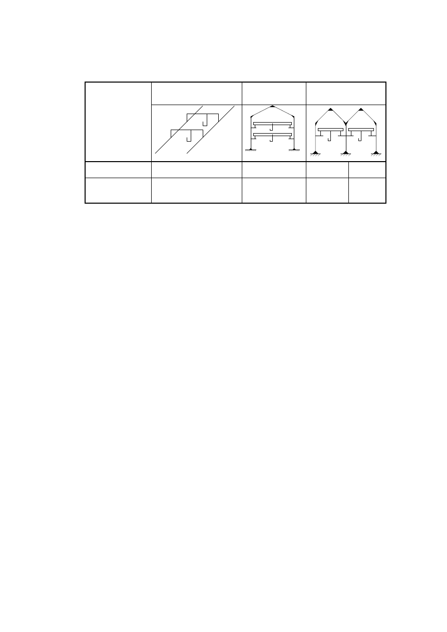
(2) The eccentricity of application e of a wheel load Q
r
to a rail should be taken as a
portion of the width of the rail head b
r
, see Figure 2.2.
NOTE: The National Annex may give the value of e. The recommended value is e = 0,25 b
r
.
b
r
Q
r
e
Figure 2.2 — Eccentricity of application of wheel load
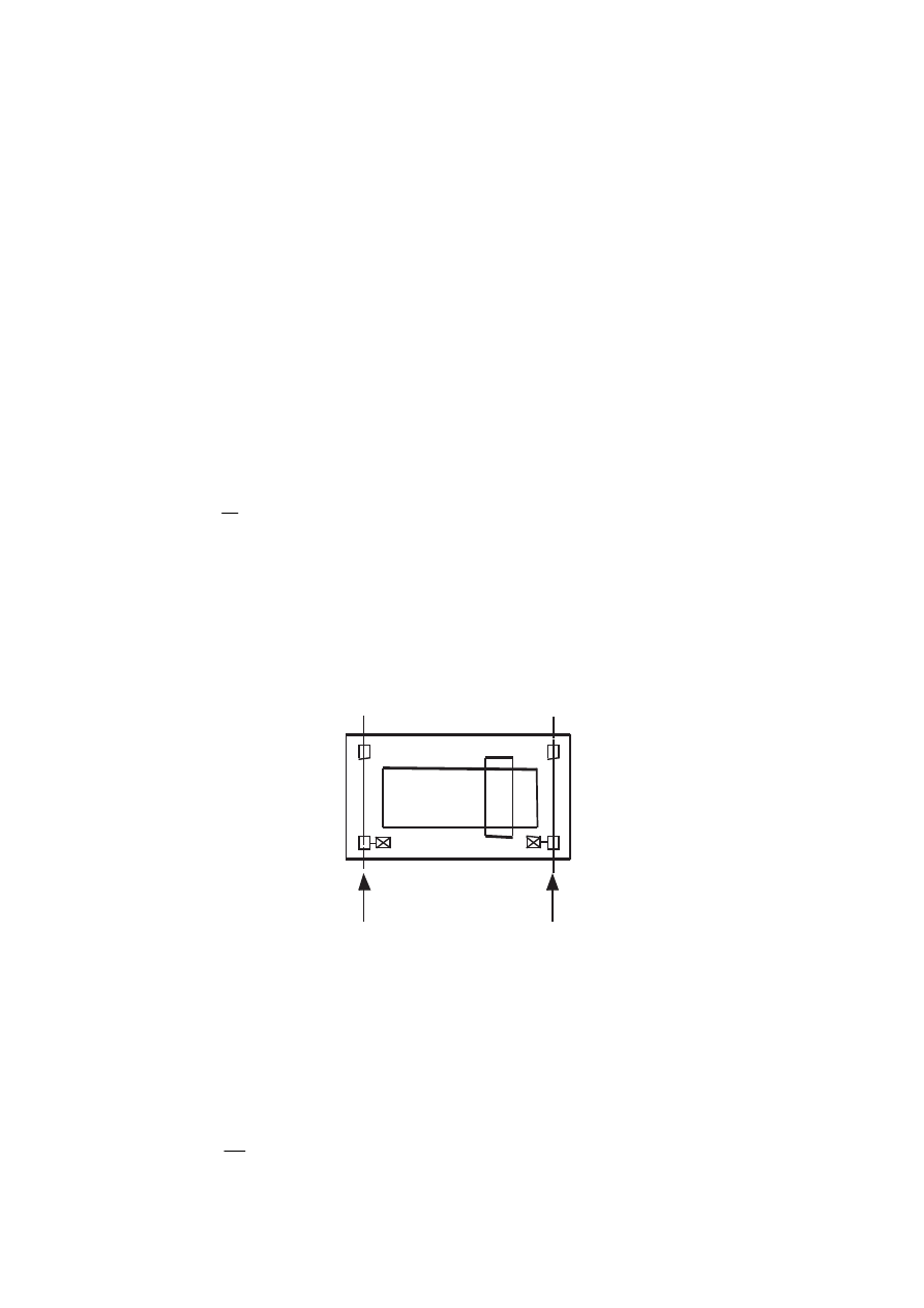
2.5.2.2 Horizontal forces
(1) The following types of horizontal forces from overhead travelling cranes should be
taken into account:
a) horizontal forces caused by acceleration or deceleration of the crane in relation to its
movement along the runway beam, see 2.7.2;
Licensed copy: BSI USER 06 Document Controller, Midmac Contracting Co. W.L.L, Version correct as of 14/10/2010
12:12, (c) BSI
EN 1991-3:2006 (E)
page 19
b) horizontal forces caused by acceleration or deceleration of the crab or underslung
trolley in relation to its movement along the crane bridge, see 2.7.5;
c) horizontal forces caused by skewing of the crane in relation to its movement along
the runway beam, see 2.7.4;
d) buffer forces related to crane movement, see 2.11.1;
e) buffer forces related to movement of the crab or underslung trolley, see 2.11.2.
(2) Unless otherwise specified, only one of the five types of horizontal forces (a) to (e)
listed in (1) should be included in the same group of simultaneous crane load
components, see Table 2.2.
(3) For underslung cranes the horizontal forces at the wheel contact surface should be
taken as at least 10 % of the maximum vertical wheel load neglecting the dynamic
component unless a more accurate value is justified.
(4) Unless otherwise specified, the longitudinal horizontal wheel forces H
L,i
and the
transverse horizontal wheel forces H
T,i
caused by acceleration and deceleration of
masses of the crane or the crab etc., should be applied as given in Figure 2.3. The
characteristic values of these forces are given in 2.7.2.
NOTE: These forces do not include the effects of oblique hoisting due to misalignment of load and
crab because in general oblique hoisting is forbidden. Any effects of unavoidable small values of
oblique hoisting are included in the inertial forces.
1
2
H
T,1
H
T,1
H
L,1
H
L,2
H
T,2
H
T,2
Key
1
Rail i = 1
2
Rail i = 2
Figure 2.3 — Load arrangement of longitudinal and transverse horizontal wheel
forces caused by acceleration and deceleration
Licensed copy: BSI USER 06 Document Controller, Midmac Contracting Co. W.L.L, Version correct as of 14/10/2010
12:12, (c) BSI
EN 1991-3:2006 (E)
page 20
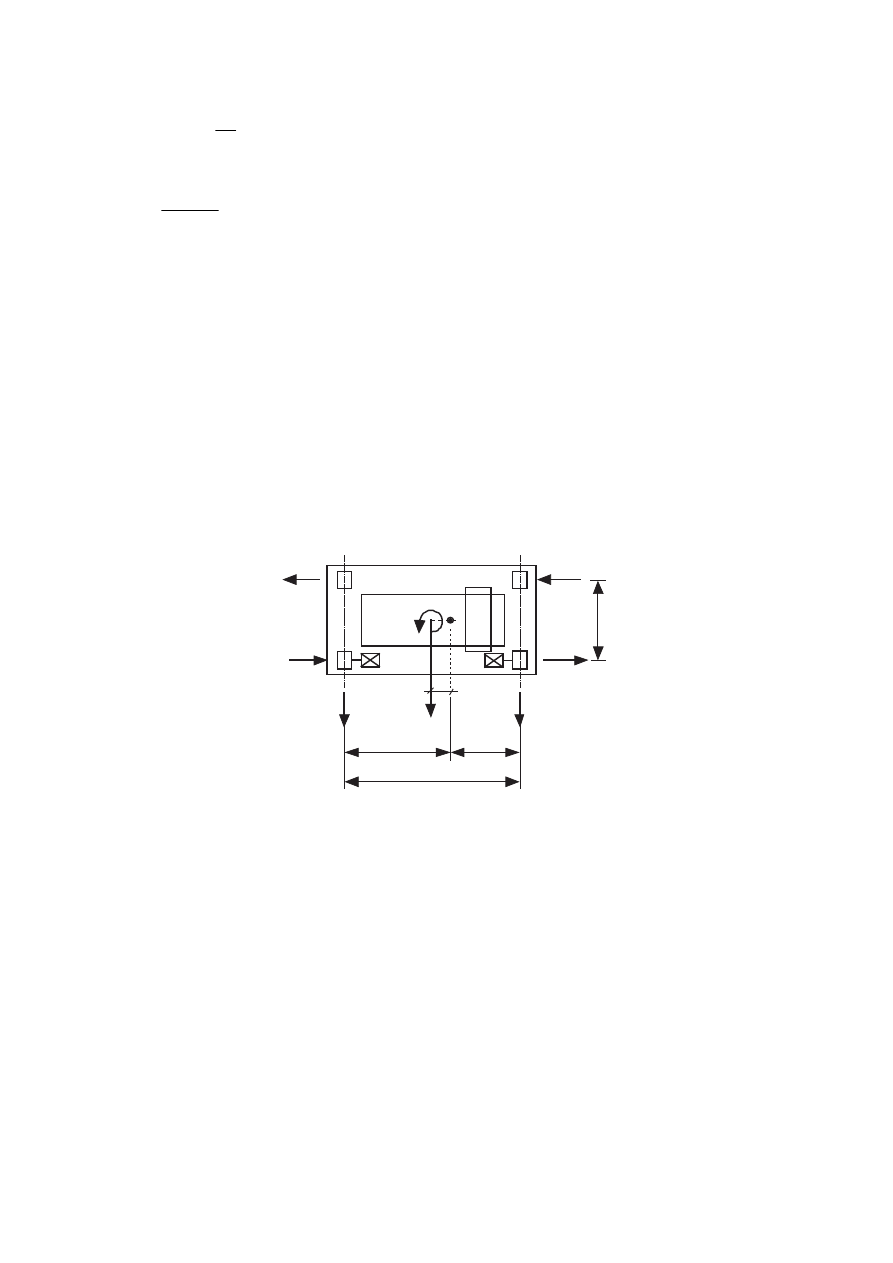
(5) The longitudinal and transverse horizontal wheel forces H
S,i,j,k
and the guide force S
caused by skewing can occur at the guidance means of cranes or trolleys while they are
travelling or traversing in steady state motion, see Figure 2.4. These loads are induced
by guidance reactions which force the wheel to deviate from their free-rolling natural
travelling or traverse direction. The characteristic values are given in 2.7.4.
α
S
4
5
6
3
2
1
H
S,1,1,T
H
S,1,2,T
H
S,2,1,T
H
S,2,2,T
H
S,1,2,L
H
S,2,2,L
1
3
2
4
5
α
S
H
S,1,1,T
H
S,2,1,T
a) with separate guidance means
b) with guidance by means of wheel flanges
Key
1
Rail i = 1
2
Rail i = 2
3
Direction of motion
4
Wheel pair j = 1
5
Wheel pair j = 2
6
Guide means
NOTE 1: The direction of the horizontal forces depends on the type of guidance means, the
direction of motion and on the type of wheel drive.
NOTE 2: The forces H
S,i,j,k
are defined in 2.7.4(1).
Figure 2.4 — Load arrangement of longitudinal and transverse horizontal wheel
forces caused by skewing
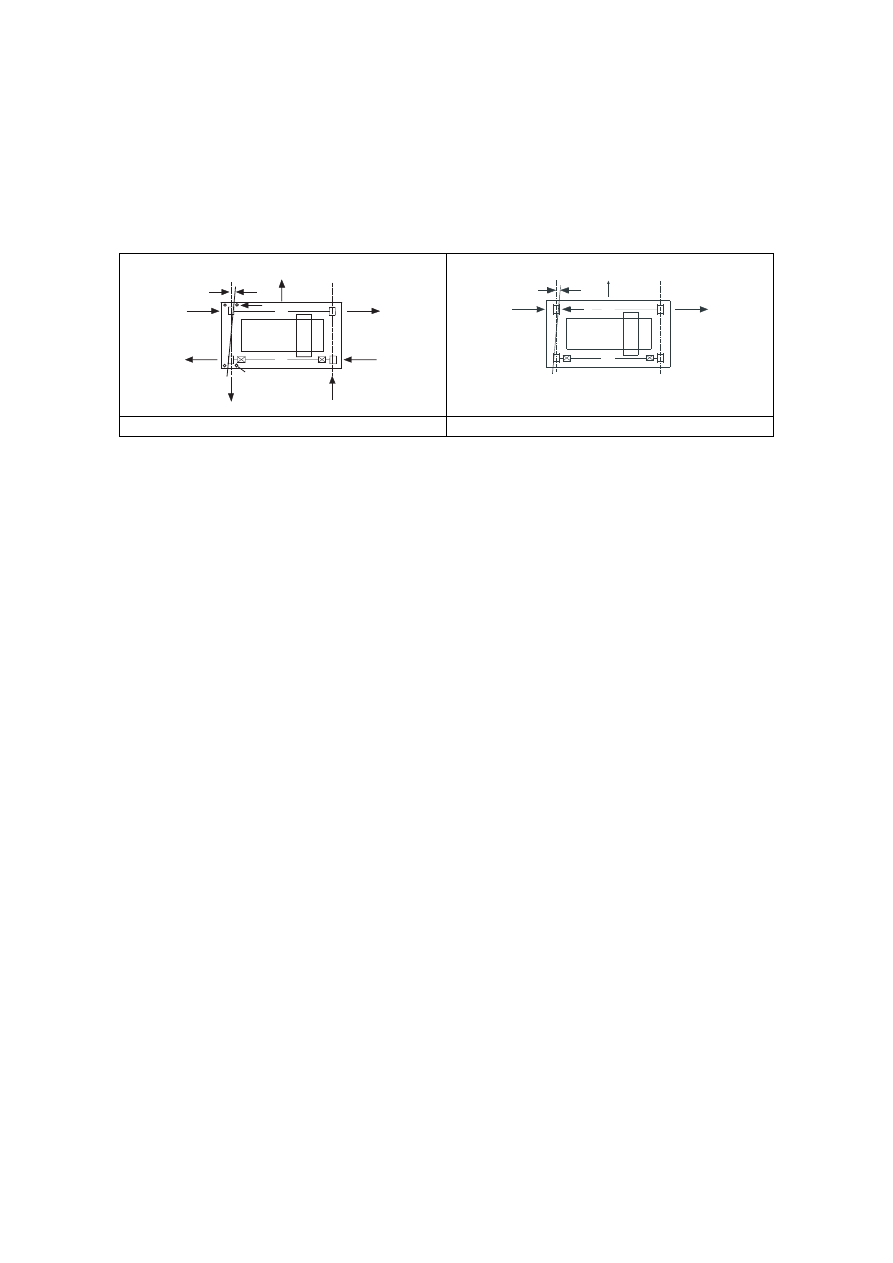
2.5.3 Multiple crane action
(1)P Cranes that are required to operate together shall be treated as a single crane action.
(2) If several cranes are operating independently, the maximum number of cranes taken
into account as acting simultaneously should be specified.
NOTE: The number of cranes to be considered in the most unfavourable position may be
specified in the National Annex. The recommended number is given in Table 2.3.
.
Licensed copy: BSI USER 06 Document Controller, Midmac Contracting Co. W.L.L, Version correct as of 14/10/2010
12:12, (c) BSI
EN 1991-3:2006 (E)
page 21
Table 2.3 — Recommended maximum number of cranes to be considered in
the most unfavourable position
Cranes to each runway
Cranes in each
shop bay
Cranes in multi – bay
buildings
Vertical crane action
3
4
4
2
Horizontal crane
action
2
2
2
2
2.6 Vertical crane loads - characteristic values
(1) The characteristic values of the vertical loads from cranes on crane supporting
structures should be determined as indicated in Table 2.2.
(2)P For the self-weight of the crane and the hoist load, the nominal values specified by
the crane supplier shall be taken as characteristic values of the vertical loads.
Licensed copy: BSI USER 06 Document Controller, Midmac Contracting Co. W.L.L, Version correct as of 14/10/2010
12:12, (c) BSI

EN 1991-3:2006 (E)
page 22
Table 2.4
—
Dynamic factors
i
ϕ
for vertical loads
Values of dynamic factors
1
ϕ
0,9 <
1
ϕ
< 1,1
The two values 1,1 and 0,9 reflect the upper and lower values of
the vibrational pulses.
2
ϕ
2
ϕ
=
h
v
2
min
,
2
β
ϕ
+
h
v
- steady hoisting speed in m/s
min
,
2
ϕ
and
2
β
see Table 2.5
3
ϕ
)
1
(
m
m
1
3
3
β
ϕ
+
∆
−
=
where
m
∆
released or dropped part of the hoisting mass
m
total hoisting mass
3
β
= 0,5
for cranes equipped with grabs or similar slow-
release devices
3
β
= 1,0 For cranes equipped with magnets or similar rapid-release
devices
4
ϕ
4
ϕ
= 1,0 provided that the tolerances for rail tracks as specified in
EN 1993-6 are observed.
NOTE: If the tolerances for rail tracks as specified in EN 1993-6 are not observed, the
dynamic factor
4
ϕ
can be determined with the model provided by EN 13001-2.
(3) If the dynamic factors
1
ϕ
,
2
ϕ
,
3
ϕ
and
4
ϕ
as specified in Table 2.1 are not included
in the specifications of the crane supplier the indications in Table 2.4 may be used.
(4) For in-service wind reference should be made to Annex A.
Table 2.5
—
Values of
2
β
and
min
,
2
ϕ
Hoisting class
of appliance
2
β
min
,
2
ϕ
HC1
HC2
HC3
HC4
0,17
0,34
0,51
0,68
1,05
1,10
1,15
1,20
NOTE: Cranes are assigned to Hoisting Classes HC1 to HC4 to allow
for the dynamic effects of transferring the load from the ground to the
crane. The selection depends on the particular type of crane, see
recommendation in annex B.
Licensed copy: BSI USER 06 Document Controller, Midmac Contracting Co. W.L.L, Version correct as of 14/10/2010
12:12, (c) BSI
EN 1991-3:2006 (E)
page 23
2.7 Horizontal crane loads - characteristic values
2.7.1 General
(1)P For the acceleration and the skewing effects, the nominal values specified by the
crane supplier shall be taken as characteristic values of the horizontal loads.
(2) The characteristic values of the horizontal loads may be specified by the crane
supplier or be determined using 2.7.2 to 2.7.5.
2.7.2 Longitudinal forces H
L,i
and transverse forces H
T,i
caused by acceleration and
deceleration of the crane
(1) The longitudinal forces H
L,i
caused by acceleration and deceleration of crane
structures result from the drive force at the contact surface between the rail and the
driven wheel, see Figure 2.5.
(2) The longitudinal forces H
L,i
applied to a runway beam may be calculated as follows:
n
K
H
r
5
i
L,
1
=
ϕ
(2.2)
where:
n
r
is the number of runway beams;
K
is the drive force according to 2.7.3;
5
ϕ
is the dynamic factor, see Table 2.6;
i
is the integer to identify the runway beam (i = 1, 2).
1
2
H
L,1
H
L,2
Key
1
Rail i = 1
2
Rail i = 2
Figure 2.5: Longitudinal horizontal forces H
L,i
(3) The moment M resulting from the drive force which should be applied at the centre
of mass is equilibrated by transverse horizontal forces H
T,1
and H
T,2
, see Figure 2.6. The
horizontal forces may be calculated as follows:
a
M
H
=
2
5
T,1
ξ
ϕ
(2.3)
Licensed copy: BSI USER 06 Document Controller, Midmac Contracting Co. W.L.L, Version correct as of 14/10/2010
12:12, (c) BSI
EN 1991-3:2006 (E)
page 24
a
M
H
=
1
5
T,2
ξ
ϕ
(2.4)
where:
Q
Q
r
max
r,
1
=
∑
∑
ξ
2
ξ
= 1 -
1
ξ
;
Σ Q
r
= Σ Q
r,max
+ Σ Q
r,(max)
;
Σ Q
r,max
see Figure 2.1;
Σ Q
r,(max)
see Figure 2.1;
a
is the spacing of the guide rollers or the flanged wheels ;
M
=
s
K l
;
ℓ
s
=
l
)
5
,
0
(
1
−
ξ
;
ℓ
is the span of the crane bridge;
5
ϕ
is the dynamic factor, see Table 2.6;
K
is the drive force, see 2.7.3 and Figure 2.7.
1
2
S
ξ
1
l
ξ
2
l
l
l
s
M
H
T,1
H
T,2
H
T,2
H
T,1
a
K
=K
1
+K
2
K
1
K
2
Key
1
Rail i = 1
2
Rail i = 2
Figure 2.6 — Definition of the transverse forces H
T,i
(4) For curved runway beams the resulting centrifugal force should be multiplied by the
dynamic factor
5
ϕ
.
(5) If the dynamic factor
5
ϕ
is not included in the specification documents of the crane
supplier, values given in Table 2.6 may be used.
Licensed copy: BSI USER 06 Document Controller, Midmac Contracting Co. W.L.L, Version correct as of 14/10/2010
12:12, (c) BSI

EN 1991-3:2006 (E)
page 25
Table 2.6 — Dynamic factor
5
ϕ
Values of the
dynamic factor
5
ϕ
Specific use
5
ϕ
= 1,0
for centrifugal forces
5
,
1
0
,
1
5
≤
≤
ϕ
for systems where forces change smoothly
0
,
2
5
,
1
5
≤
≤
ϕ
for cases where sudden changes can occur
5
ϕ
= 3,0
for drives with considerable backlash
2.7.3 Drive force K
(1) The drive force K on a driven wheel should be taken such that wheel spin is
prevented.
(2) The drive force K should be obtained from the crane supplier.
(3) Where no wheel controlled system is applied, the drive force K may be calculated as
follows:
K
= K
1
+ K
2
=
µ
∑ Q
*
r,min
(2.5)
where:
µ
is the friction factor;
– for a single wheel drive: Σ Q
*
r,min
= m
w
Q
r,min
, where m
w
is the number of single
wheel drives;
– for a central wheel drive: Σ Q
*
r,min
= Q
r,min
+ Q
r,(min)
;
NOTE 1: Modern cranes do not normally have a central wheel drive.
NOTE 2: The value of the friction factor may be given in the National Annex. The recommended
values are:
µ
= 0,2 for steel - steel;
µ
= 0,5 for steel - rubber.
Licensed copy: BSI USER 06 Document Controller, Midmac Contracting Co. W.L.L, Version correct as of 14/10/2010
12:12, (c) BSI
EN 1991-3:2006 (E)
page 26
1
2
K
1
K
2
1
2
K
1
K
2
a) Central wheel drive
b) Single wheel drive
Key
1
Rail i = 1
2
Rail i = 2
Figure 2.7 — Definition of the drive force K
2.7.4 Horizontal forces H
S,i,j,k
and the guide force S caused by skewing of the crane
(1) The guide force S and the transverse forces H
S,i,j,k
caused by skewing may be
obtained from:
S
=
r
j
S,
Q
f
∑
λ
(2.6)
H
S,1,j,L
=
r
L
j,
,
1
,
Q
f
S
∑
λ
(index j indicates the driven wheel pair )
(2.7)
H
S,2,j,L
=
r
L
j,
,
2
,
Q
f
S
∑
λ
(index j indicates the driven wheel pair )
(2.8)
H
S,1,j,T
=
r
T
j,
,
1
,
Q
f
S
∑
λ
(2.9)
H
S,2,j,T
=
r
T
j,
,
2
,
Q
f
S
∑
λ
(2.10)
where:
f
is the “non-positive factor”, see (2);
k
j
i
S
,
,
,
λ
is the force factor, see (4);
i
is the rail i;
j
is the wheel pair j;
k
is the direction of the force (L = longitudinal, T = transverse).
(2) The “non-positive” factor may be determined from:
f
= 0,3 (1 - exp (-250
α)) ≤ 0,3
(2.11)
where:
α is the skewing angle, see (3).
(3) The skewing angle
α
, see Figure 2.8, which should be equal to or less than
0,015 rad, should be chosen taking into account the space between the guidance means
and the rail as well as reasonable dimensional variation and wear of the appliance
wheels and the rails. It may be determined as follows:
Licensed copy: BSI USER 06 Document Controller, Midmac Contracting Co. W.L.L, Version correct as of 14/10/2010
12:12, (c) BSI

EN 1991-3:2006 (E)
page 27
rad
015
,
0
0
V
F
≤
+
+
=
α
α
α
α
(2.12)
where:
V
F
,
α
α
and
0
α
are as defined in Table 2.7.
Table 2.7 — Definition of
V
F
,
α
α
and
0
α
Angles
i
α
Minimum values of
i
α
0,75x
≥ 5 mm for guide rollers
F
α
=
ext
0,75
a
x
0,75x
≥ 10 mm for wheel flanges
y
≥ 0,03b mm for guide rollers
V
α
=
ext
a
y
y
≥ 0,10b mm for wheel flanges
0
α
0
α
= 0,001
Where:
a
ext
is the spacing of the outer guidance means or flanged wheels
on the
guiding rail;
b
is the width of the rail head;
x
is the track clearance between the rail and the guidance
means (lateral slip);
y
is the wear of the rail and the guidance means;
0
α
is the tolerance on wheel and rail directions.
(4) The force factor
k
,
j
,
i
,
S
λ
depends on the combination of the wheel pairs and the
distance h between the instantaneous centre of rotation and the relevant guidance means,
i.e. the front ones in the direction, see Figure 2.8. The value of the distance h may be
taken from Table 2.8. The force factor
k
,
j
,
i
,
S
λ
may be determined from the expressions
given in Table 2.9.
Licensed copy: BSI USER 06 Document Controller, Midmac Contracting Co. W.L.L, Version correct as of 14/10/2010
12:12, (c) BSI
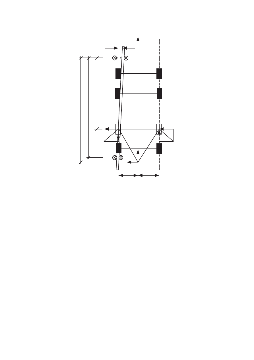
EN 1991-3:2006 (E)
page 28
1
2
3
5
ξ
1
l
ξ
2
l
x
y
7
α
4
6
x
5
H
s,1,j,T
H
s,1,j,L
H
s,2,j,L
H
s,2,j,T
h
a
ext
e
j
Key
1
Rail i = 1
2
Rail i = 2
3
Direction of motion
4
Direction of rail
5
Guidance means
6
Wheel pair j
7
Instantaneous centre of rotation
Figure 2.8 — Definition of angle
α
and the distance h
Licensed copy: BSI USER 06 Document Controller, Midmac Contracting Co. W.L.L, Version correct as of 14/10/2010
12:12, (c) BSI
EN 1991-3:2006 (E)
page 29
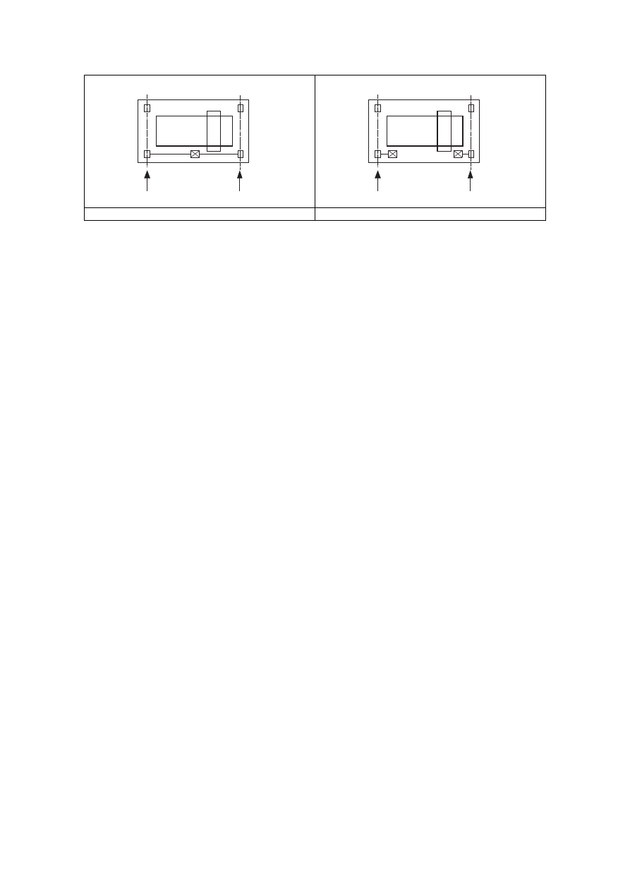
Table 2.8 — Determination of the distance h
Combination of wheel pairs
Fixing of wheels
according to lateral
movements
coupled (c)
independent (i)
h
Fixed/Fixed
FF
e
e
m
j
2
j
2
2
1
+
Σ
Σ
l
ξ
ξ
Fixed/Movable
FM
e
e
m
j
2
j
2
1
+
Σ
Σ
l
ξ
Where:
h
is the distance between the instantaneous centre of rotation and the relevant guidance
means;
m
is the number of pairs of coupled wheels (m = 0 for independent wheel pairs);
l
1
ξ
is the distance of the instantaneous centre of rotation from rail 1;
l
2
ξ
is the distance of the instantaneous centre of rotation from rail 2;
ℓ
is the span of the appliance;
e
j
is the distance of the wheel pair j from the relevant guidance means.
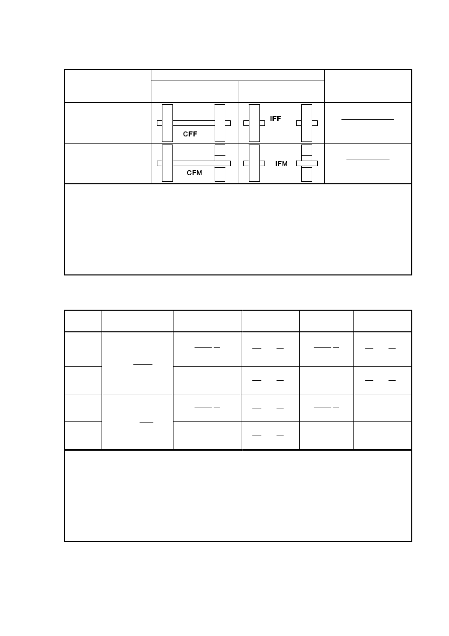
Table 2.9 — Definition of
k
j
i
S
,
,
,
λ
– values
System
j
,
S
λ
L
,
j
,
1
,
S
λ
T
,
j
,
1
,
S
λ
L
,
j
,
2
,
S
λ
T
,
j
,
2
,
S
λ
CFF
h
n
l
2
1
ξ
ξ
h
e
n
j
2
-
1
ξ
h
n
l
2
1
ξ
ξ
h
e
n
j
1
-
1
ξ
IFF
nh
e
∑
−
j
1
0
h
e
n
j
2
-
1
ξ
0
h
e
n
j
1
-
1
ξ
CFM
h
n
l
2
1
ξ
ξ
h
e
n
j
2
-
1
ξ
h
n
l
2
1
ξ
ξ
0
IFM
Σ
nh
e
j
2
-
1
ξ
0
h
e
n
j
2
-
1
ξ
0
0
Where:
n
is the number of wheel pairs;
l
1
ξ
is the distance of the instantaneous centre of rotation from rail 1;
l
2
ξ
is the distance of the instantaneous centre of rotation from rail 2;
ℓ
is the span of the appliance;
e
j
is the distance of the wheel pair j from the relevant guidance means;
h
is the distance between the instantaneous centre of rotation and the relevant guidance
means.
Licensed copy: BSI USER 06 Document Controller, Midmac Contracting Co. W.L.L, Version correct as of 14/10/2010
12:12, (c) BSI

EN 1991-3:2006 (E)
page 30
2.7.5 Horizontal force H
T,3
caused by acceleration or deceleration of the crab
(1) The horizontal force H
T,3
caused by acceleration or deceleration of the crab or trolley
may be assumed to be covered by the horizontal force H
B,2
given in 2.11.2.
2.8 Temperature effects
(1)P The action effects on runways due to temperature variations shall be taken into
account where necessary. In general, non-uniform distributed temperature need not be
considered.
(2) For the temperature difference for outdoor runways see EN 1991-1-5.
2.9 Loads on access walkways, stairs, platforms and guard rails
2.9.1 Vertical loads
(1) Unless otherwise stated, the access walkways, stairs and platforms should be loaded
by a vertical load Q spread over a square surface of 0,3m × 0,3m.
(2) Where materials can be deposited a vertical load Q
k
= 3 kN should be applied.
(3) If the walkways, stairs and platforms are provided for access only, the characteristic
value in (2) may be reduced to 1,5 kN.
(4) The vertical load Q
k
may be disregarded if the structural member considered is
subjected to crane actions.
2.9.2 Horizontal loads
(1) Unless otherwise stated, the guard rail should be loaded by a single horizontal load
H
k
= 0,3 kN.
(2) The horizontal load H
k
may be disregarded if all structural members are subjected to
crane actions.
2.10 Test loads
(1) When tests are performed after erection of the cranes on the supporting structures,
the supporting structure should be checked against the test loading conditions.
(2) If relevant, the crane supporting structure should be designed for these test loads.
(3)P The hoist test load shall be amplified by a dynamic factor
6
ϕ
.
(4) When considering test loads the following cases should be distinguished:
– Dynamic test load:
The test load is moved by the drives in the way the crane will be used. The test load
should be at least 110 % of the nominal hoist load.
Licensed copy: BSI USER 06 Document Controller, Midmac Contracting Co. W.L.L, Version correct as of 14/10/2010
12:12, (c) BSI
EN 1991-3:2006 (E)
page 31
)
1,0
(
5
,
0
=
2
6
ϕ
ϕ
+
(2.13)
– Static test load:
The load is increased for testing by loading the crane without the use of the drives.
The test load should be at least 125 % of the nominal hoist load.
1,0
=
6
ϕ
(2.14)
2.11 Accidental actions
2.11.1 Buffer forces H
B,1
related to crane movement
(1)P Where buffers are used, the forces on the crane supporting structure arising from
collision with the buffers shall be calculated from the kinetic energy of all relevant parts
of the crane moving at 0,7 to 1,0 times the nominal speed.
(2) The buffer forces multiplied by
7
ϕ
according to Table 2.10, to make allowance for
dynamic effects, may be calculated taking into account the distribution of relevant
masses and the buffer characteristics, see Figure 2.9b.
S
m
H
B
c
1
7
1
B,
=
ν
ϕ
(2.15)
where:
7
ϕ
see Table 2.10;
v
1
is 70 % of the long travel velocity (m/s);
m
c
is the mass of the crane and the hoist load (kg);
S
B
is the spring constant of the buffer (N/m).
Table 2.10 — Dynamic factor
7
ϕ
Values of dynamic factor
7
ϕ
Buffer characteristic
7
ϕ
= 1,25
0,0
≤
b
ξ
≤ 0,5
7
ϕ
= 1,25 + 0,7 (
b
ξ
- 0,5)
0,5
≤
b
ξ
≤ 1
NOTE:
b
ξ
may be approximately determined from Figure 2.9
Licensed copy: BSI USER 06 Document Controller, Midmac Contracting Co. W.L.L, Version correct as of 14/10/2010
12:12, (c) BSI
EN 1991-3:2006 (E)
page 32
1
2
S
F
x1
F
x2
F
x2
F
x1
δ
δ
ξ
δ
ϕ
b
1
7
1,60
1,25
1,00
0,5
1,0
F
x,j
a) Buffer force
b) Buffer characteristic
∫
=
u
b
du
F
u
F
0
1
ξ
Key
1
Buffer characteristic
NOTE: For additional information about the characteristic of buffers see EN 13001-2.
Figure 2.9 — Definition of the buffer force
2.11.2 Buffer forces H
B,2
related to movements of the crab
(1) Provided that the payload is free to swing, the horizontal load H
B,2
representing the
buffer forces related to movement of the crab or trolley may be taken as 10 % of the sum
of the hoist load and the weight of the crab or trolley. In other cases the buffer force
should be determined as for crane movement, see 2.11.1.
2.11.3 Tilting forces
(1)P If a crane with horizontally restrained loads can tilt when its load or lifting
attachment collides with an obstacle, the resulting static forces shall be considered.
2.12 Fatigue loads
2.12.1 Single crane action
(1)P Fatigue loads shall be determined such that the operational conditions of the
distribution of hoist loads and the effects of the variation of crane positions to the
fatigue details are duly considered.
NOTE: Where sufficient information on the operational conditions is available, the fatigue loads
may be determined according to EN 13001 and EN 1993-1-9, Annex A. Where this information is
not available, or where a simplified approach is favoured, the following rules apply.
(2) For normal service conditions of the crane the fatigue loads may be expressed in
terms of fatigue damage equivalent loads Q
e
that may be taken as constant for all crane
positions to determine fatigue load effects.
NOTE: The procedure is compatible with EN 13001 however it is a simplified approach for gantry
girders to comply with incomplete information during the design stage.
Licensed copy: BSI USER 06 Document Controller, Midmac Contracting Co. W.L.L, Version correct as of 14/10/2010
12:12, (c) BSI

EN 1991-3:2006 (E)
page 33
(3) The fatigue damage equivalent load Q
e
may be determined such that it includes the
effects of the stress histories arising from the specified service conditions and the ratio
of the absolute number of load cycles during the expected design life of the structure to
the reference value N = 2,0
× 10
6
cycles.
Table 2.11 — Classification of the fatigue actions from cranes
according to EN 13001-1
Class of load spectrum
Q
0
Q
1
Q
2
Q
3
Q
4
Q
5
kQ
≤
0,03
13
0,0313
<
kQ
≤
0,0625
0,0625
<
kQ
≤
0,125
0,125
<
kQ
≤
0,25
0,25
<
kQ
≤
0,5
0,5
<
kQ
≤
1,0
class of
total number of cycles
U
0
C
≤
1,6
@10
4
S
0
S
0
S
0
S
0
S
0
S
0
U
1
1,6
×
10
4
<
C
≤
3,15
×
10
4
S
0
S
0
S
0
S
0
S
0
S
1
U
2
3,15
×
10
4
<
C
≤
6,30
×
10
4
S
0
S
0
S
0
S
0
S
1
S
2
U
3
6,30
×
10
4
<
C
≤
1,25
×
10
5
S
0
S
0
S
0
S
1
S
2
S
3
U
4
1,25
×
10
5
<
C
≤
2,50
×
10
5
S
0
S
0
S
1
S
2
S
3
S
4
U
5
2,50
×
10
5
<
C
≤
5,00
×
10
5
S
0
S
1
S
2
S
3
S
4
S
5
U
6
5,00
×
10
5
<
C
≤
1,00
×
10
6
S
1
S
2
S
3
S
4
S
5
S
6
U
7
1,00
×
10
6
<
C
≤
2,00
×
10
6
S
2
S
3
S
4
S
5
S
6
S
7
U
8
2,00
×
10
6
<
C
≤
4,00
×
10
6
S
3
S
4
S
5
S
6
S
7
S
8
U
9
4,00
×
10
6
<
C
≤
8,00
×
10
6
S
4
S
5
S
6
S
7
S
8
S
9
where:
k
Q is a load spectrum factor for all tasks of the crane;
C
is the total number of working cycles during the design life of the crane.
NOTE: The classes S
i
are classified by the stress effect history parameter s in EN 13001-1 which is defined
as:
s =
υ
k
where:
k
is the stress spectrum factor;
υ
is the number of stress cycles C related to 2,0
×
10
6
stress cycles.
The classification is based on a total service life of 25 years.
(4) The fatigue load may be specified as:
i
max,
i
fat
e
Q
Q
λ
ϕ
=
(2.16)
where:
Q
max,i
is the maximum value of the characteristic vertical wheel load i;
λ
λ
λ
i
2,
i
1,
i
=
is the damage equivalent factor to make allowance for the relevant
standardized fatigue load spectrum and absolute number of load cycles in
relation to N = 2,0
× 10
6
cycles;
Licensed copy: BSI USER 06 Document Controller, Midmac Contracting Co. W.L.L, Version correct as of 14/10/2010
12:12, (c) BSI

EN 1991-3:2006 (E)
page 34
∑
∆
∆
∑
n
n
Q
Q
kQ
m
m
m
j
i,
j
i,
i
j
i,
j
/
1
i
1,
max
=
=
λ
(2.17)
∑
N
n
m
m
j
i,
j
/
1
=
n
=
i
2,
ν
λ
(2.18)
where:
∆ Q
i,j
is the load amplitude of range j for wheel i: ∆ Q
i,j
= Q
i,j
- Q
min,i
;
max ∆ Q
i
is the maximum load amplitude for wheel i: max ∆ Q
i
= Q
max,i
- Q
min,i
;
kQ
,
ν
are the damage equivalent factors;
m
is the slope of the fatigue strength curve;
fat
ϕ
is the damage equivalent dynamic impact factor, see (7);
i
is the number of the wheel
N
is
6
10
2
×
NOTE: For the value of m see EN 1993-1-9, see also notes to Table 2.12.
(5) For determining the
λ
-value the use of cranes may be classified according to the
load spectrum and the total number of load cycles as indicated in Table 2.11.
(6)
λ
-values may be taken from Table 2.12 according to the crane classification.
Table 2.12 —
i
λ
-values according to the classification of cranes
Classes
S
S
0
S
1
S
2
S
3
S
4
S
5
S
6
S
7
S
8
S
9
normal
stresses
0,198
0,250
0,315
0,397
0,500
0,630
0,794
1,00
1,260
1,587
shear
stresses
0,379
0,436
0,500
0,575
0,660
0,758
0,871
1,00
1,149
1,320
NOTE 1: In determining the
λ
-values standardized spectra with a gaussian distribution of the load effects, the
Miner rule and fatigue strength S-N lines with a slope m = 3 for normal stresses and m = 5 for shear stress have
been used.
NOTE 2: In case the crane classification is not included in the specification documents of the crane indications
are given in Annex B.
(7) The damage equivalent dynamic impact factor
fat
ϕ
for normal conditions may be
taken as:
2
+
1
=
1
fat,1
ϕ
ϕ
and
2
+
1
=
2
fat,2
ϕ
ϕ
(2.19)
Licensed copy: BSI USER 06 Document Controller, Midmac Contracting Co. W.L.L, Version correct as of 14/10/2010
12:12, (c) BSI

EN 1991-3:2006 (E)
page 35
2.12.2 Stress range effects of multiple wheel or crane actions
(1) The stress range due to damage equivalent wheel loads Q
e
may be determined from
the evaluation of stress histories for the fatigue detail considered.
NOTE: For simplified approaches using the values
i
λ
from Table 2.12, see EN 1993-6, 9.4.2.3.
Licensed copy: BSI USER 06 Document Controller, Midmac Contracting Co. W.L.L, Version correct as of 14/10/2010
12:12, (c) BSI

EN 1991-3:2006 (E)
page 36
Section 3 Actions induced by machinery
3.1 Field of application
(1) This section applies to structures supporting rotating machines which induce
dynamic effects in one or more planes.
(2) This section presents methods to determine the dynamic behaviour and action effects
to verify the safety of the structure.
NOTE: Though a precise limit cannot be set, in general it may be assumed that for minor
machinery with only rotating parts and weighing less than 5 kN or having a power less than 50 kW,
the action effects are included in the imposed loads and separate considerations are therefore not
necessary. In these cases the use of so called vibration absorbers under the supporting frame is
sufficient to protect the machine and the surroundings. Examples are washing machines and small
ventilators.
3.2 Classification of actions
3.2.1 General
(1)P Actions from machinery are classified as permanent, variable and accidental
actions which are represented by various models as described in 3.2.2 to 3.2.4.
3.2.2 Permanent actions
(1) Permanent actions during service include the self-weight of all fixed and moveable
parts and static actions from service such as:
– self-weight of rotors and the hull (vertical);
– self-weight of condensers, if relevant, taking account of the water infill (vertical);
– actions from vacuum for turbines, the condensers of which are connected to the hull
by compensators. (vertical and horizontal);
– drive torques of the machine transmitted to the foundation by the hull (pairs of
vertical forces);
– forces from friction at the bearings induced by thermal expansion of the hull
(horizontal);
– actions from self-weight, forces and moments from pipes due to thermal expansion,
actions from gas; flow and gas pressure (vertical and horizontal);
– temperature effects from the machine and pipes, for instance temperature differences
between machine and pipes and the foundation.
(2) Permanent actions during transient stages (erection, maintenance or repair) are those
from self-weight only including those from hoisting equipments, scaffolding or other
auxiliary devices.
Licensed copy: BSI USER 06 Document Controller, Midmac Contracting Co. W.L.L, Version correct as of 14/10/2010
12:12, (c) BSI

EN 1991-3:2006 (E)
page 37
3.2.3 Variable actions
(1) Variable actions from machinery during normal service are dynamic actions caused
by accelerated masses such as:
– periodic frequency-dependent bearing forces due to eccentricities of rotating masses
in all directions, mainly perpendicular to the axis of the rotors;
– free mass forces or mass moments;
– periodic actions due to service depending on the type of machine that are transmitted
by the hull or bearings to the foundations;
– forces or moments due to switching on or off or other transient procedures such as
synchronisations.
3.2.4 Accidental actions
(1) Accidental actions can occur from:
– accidental magnification of the eccentricity of masses (for instance by fracture of
brakes or accidental deformation or rupture of axle of moveable parts);
– short circuit or out of synchronisation of the generators and machines;
– impact effects from pipes by shutting down.
3.3 Design situations
(1)P The relevant actions induced by machinery shall be determined for each design
situation identified in accordance with EN 1990.
(2)P Design situations shall in particular be selected for verifying that:
– the service conditions of the machinery conform to the service requirements and no
damage is induced to the structure supporting the machine and its foundation by
accidental actions that would infringe the subsequent use of this structure for further
service;
– the impact on the surroundings, for instance disturbance of sensitive equipment, is
within acceptable limits;
– no ultimate limit state can occur in the structure;
– no fatigue limit state can occur in the structure.
NOTE: Unless specified otherwise, the serviceability requirements should be determined for the
individual project.
3.4 Representation of actions
3.4.1 Nature of the loads
(1)P In the determination of action effects a distinction shall be made between the static
and the dynamic action effects.
Licensed copy: BSI USER 06 Document Controller, Midmac Contracting Co. W.L.L, Version correct as of 14/10/2010
12:12, (c) BSI
EN 1991-3:2006 (E)
page 38
(2)P In the static actions both those from machinery and those from the structure shall
be included.
NOTE: Static actions from machinery are the permanent actions defined in 3.2.2. They may be
used for determining creep effects or for verifying that prescribed limitations of static deformations
are not exceeded.
(3)P The dynamic action effects shall be determined taking into account the interaction
between the excitation from the machinery and the structure.
NOTE: The dynamic actions from the machinery are the variable actions defined in 3.2.3.
(4)P Dynamic action effects shall be determined by a dynamic calculation with an
appropriate modelling of the vibration system and the dynamic action, see 3.4.2.
(5) Dynamic effects may be disregarded where not relevant.
3.4.2 Modelling of dynamic actions
(1) The dynamic actions of machines with only rotating parts, e.g. rotating compressors,
turbines, generators and ventilators, consist of periodically changing forces which may
be defined by a sinusoidal function, see Figure 3.1.
(2) A short circuit M
k
(t) moment may be represented by a combination of sinusoidal
moment-time diagrams acting between the rotor and the hull.
Figure 3.1 — Harmonic force
3.4.3 Modelling of the machinery-structure interaction
(1)P The vibration system composed of the machine and the structure shall be modelled
such that the excitations, the mass quantities, stiffness properties and the damping are
sufficiently taken into account to determine the actual dynamic behaviour.
(2) The model may be linear elastic with concentrated or distributed masses connected
with springs and supported by springs.
(3) The common centre of gravity of the system (for instance of the foundation and
machine) should be located as near as possible to the same vertical line as the centroid
of the foundation area in contact with the soil. In any case the eccentricity in the
distribution of masses should not exceed 5 % of the length of the side of the contact
area. In addition, the centre of gravity of the machine and foundation system should if
possible be below the top of the foundation block.
Licensed copy: BSI USER 06 Document Controller, Midmac Contracting Co. W.L.L, Version correct as of 14/10/2010
12:12, (c) BSI

EN 1991-3:2006 (E)
page 39
(4) In general the three possible degrees of freedom for translations and the three
degrees of freedom for rotations should be considered; it is however in general not
necessary to apply a three dimensional model.
(5) The properties of the supporting medium of the foundation structure should be
converted in terms of the model (springs, damping constants etc.). The required
properties are:
– for soils: dynamic G-modulus and damping constants;
– for piles: dynamic spring constants in vertical and horizontal directions
– for springs: spring constants in horizontal and vertical directions and for rubber
springs the damping data.
3.5 Characteristic values
(1) A complete survey of the static and dynamic forces for the various design situations
should be obtained from the machine manufacturer together with all other machine data
such as outline drawings, weights of static and moving parts, speeds, balancing etc.
(2) The following data should be obtained from the machine manufacturer:
– loading diagram of the machine showing the location, magnitude and direction of all
loads including dynamic loads;
– speed of the machine;
– critical speeds of the machine;
– outline dimensions of the foundation;
– mass moment of inertia of the machine components;
– details of inserts and embedments;
– layout of piping, ducting etc, and their supporting details;
– temperatures in various zones during operation;
– allowable displacements at the machine bearing points during normal operation.
(3) In simple cases, the dynamic forces (free forces) for rotating machine parts may be
determined as follows:
)
(
M
r
r
R
M
2
r
R
s
e
m
e
m
F
ω
ω
ω
=
=
(3.1)
where:
F
s
is the free force of the rotor;
m
R
is the mass of the rotor;
r
ω
is the circular frequency of the rotor (rad/s);
e
M
is the eccentricity of the rotor mass;
e
r
ω
is the accuracy of balancing of the rotor, expressed as a velocity amplitude.
(4) For the accuracy of balancing, the following situations should be considered:
Licensed copy: BSI USER 06 Document Controller, Midmac Contracting Co. W.L.L, Version correct as of 14/10/2010
12:12, (c) BSI

EN 1991-3:2006 (E)
page 40
– persistent situation:
the machine is well balanced. However, with time the balance of the machines
decreases to a degree that is just acceptable for normal operation. A warning system
on the machine ensures that the operator is warned in case of exceeding a certain
limit. Up to that state of balance no detrimental vibration may occur to the structure
and the surroundings and the requirements concerning the vibration level are to be
fulfilled.
– accidental situation:
the balance is completely disturbed by an accidental event: the monitoring system
ensures the switch off of the machine. The structure is to be strong enough to
withstand the dynamic forces.
(5) In simple cases the interaction effect from the excitation of a machine with a rotating
mass and the dynamic behaviour of the structure may be expressed by a static equivalent
force:
M
s
eq
ϕ
F
F
=
(3.2)
where:
s
F
is the free force of the rotor;
M
ϕ
is the dynamic factor which depends on the ratio of the natural frequency n
e
(or
e
ω
) of the structure to the frequency of the exciting force n
s
(or
s
ω
) and the
damping ratio
ζ
.
(6) For harmonically varying forces (free forces of rotating equipment) the
magnification factor may be calculated in the following way:
a) for small damping or far from resonance
ω
ω
ω
ϕ
2
s
2
e
2
e
M
-
=
(3.3)
b) in case of resonance
e
ω
=
s
ω
and a damping ratio
ζ
ω
ω
ζ
ω
ω
ϕ
e
s
2
2
e
2
s
2
2
/
1
-
M
2
+
-
1
=
(3.4)
(7) If the time history of the short circuit moment M
k
(t) is not indicated by the
manufacturer, the following expression may be used:
Ω
Ω
−
−
−
-
1
-
2
sin
2
1
-
sin
10
=
)
(
15
,
0
o
N
4
,
0
N
4
,
0
o
k
t
m
t
m
t
m
e
M
t
e
t
e
M
t
M
(3.5)
Licensed copy: BSI USER 06 Document Controller, Midmac Contracting Co. W.L.L, Version correct as of 14/10/2010
12:12, (c) BSI

EN 1991-3:2006 (E)
page 41
where:
M
o
is the nominal moment resulting from the effective power;
Ω
N
is the angular frequency of the electric circuit (rad/s);
t
is the time (s).
(8) For natural frequencies in the range 0,95 Ω
N
to 1,05 Ω
N
the calculated frequencies
of the electric circuit should be identical with these natural frequencies.
(9) As a simplification, an equivalent static moment may be calculated in the following
way:
k,eq
k,max
,
M
M
= 1 7
(3.6)
where:
M
k,max
is the peak value of the circuit moment M
k
(t).
(10) If no indication on M
k,max
is given from the manufacturer the following value may
be used:
k,max
o
M
M
= 12
(3.7)
3.6 Serviceability criteria
(1) Serviceability criteria are, in general, related to vibration movements of:
a) the axis of the machine and its bearings;
b) extreme points of the structure and the machinery.
(2) Characteristics of the movements are:
– the displacement amplitude A;
– the velocity amplitude
s
ω
A;
– the acceleration amplitude
2
s
ω
A.
(3)P In calculating the amplitudes of the system, the translational vibrations as well as
the rotational vibrations caused by the dynamic forces and moments shall be taken into
account and also the range of the stiffness properties of the foundation and the
supporting medium (soil, piles).
(4) In the simple case of a one mass spring system, see Figure 3.2, the displacement
amplitudes may be calculated as follows:
k
F
A
eq
=
(3.8)
Licensed copy: BSI USER 06 Document Controller, Midmac Contracting Co. W.L.L, Version correct as of 14/10/2010
12:12, (c) BSI
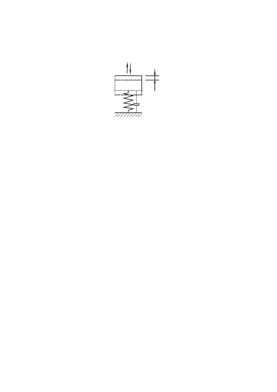
EN 1991-3:2006 (E)
page 42
where:
k
is the spring constant of the system.
F
s
A
m
k
c
Figure 3.2 — Mass spring system
Licensed copy: BSI USER 06 Document Controller, Midmac Contracting Co. W.L.L, Version correct as of 14/10/2010
12:12, (c) BSI

EN 1991-3:2006 (E)
page 43
Annex A (normative)
Basis of design – supplementary clauses to EN 1990 for
runway beams loaded by cranes
A.1 General
(1) This annex gives rules on partial factors for actions (
γ
factors), and on combinations
of crane loads on runway beams with permanent actions, quasistatic wind, snow and
temperature actions and on the relevant
ψ
factors.
(2) If other actions need to be considered (for instance mining subsidence) the
combinations should be supplemented to take them into account. The combinations
should also be supplemented and adapted for the execution phases.
(3) When combining a group of crane loads together with other actions, the group of
crane loads should be considered as a single action.
(4) When considering combinations of actions due to crane loads with other actions the
following cases should be distinguished:
– runways outside buildings;
– runways inside buildings where climatic actions are resisted by the buildings and
structural elements of the buildings may also be loaded directly or indirectly by
crane loads.
(5) For runways outside buildings the characteristic wind action on the crane structure
and on the hoisting equipment may be assessed in accordance with EN 1991-1-4 as a
characteristic force F
wk
.
(6) When considering combinations of hoist loads with wind action, the maximum wind
force compatible with crane operations should also be considered. This force F
*
w
is
associated with a wind speed equal to 20 m/s. The reference area A
ref,x
for the hoist load
should be determined for each specific case.
(7) For runways inside buildings, wind actions and snow loads on the crane structure
may be neglected; however in structural parts of the building that are loaded by wind,
snow and crane loads the appropriate load combinations should be considered.
A.2 Ultimate limit states
A.2.1 Combinations of actions
(1) For each critical load case, the design values of the effects of actions should be
determined by combining the values of actions which occur simultaneously in
accordance with EN 1990.
(2) Where an accidental action is to be considered no other accidental action nor wind
nor snow action need be considered to occur simultaneously.
Licensed copy: BSI USER 06 Document Controller, Midmac Contracting Co. W.L.L, Version correct as of 14/10/2010
12:12, (c) BSI
EN 1991-3:2006 (E)
page 44
A.2.2 Partial factors
(1) For ULS verifications governed by the strength of structural material or of the
ground, the partial factors on actions for ultimate limit states in the persistent, transient
and accidental design situations should be defined. For case EQU, see (2) below.
NOTE: The values of the
γ
-factors may be set in the National Annex. For the design of runway
beams the
γ
-values given in Table A.1 are recommended. They cover cases STR and GEO
specified for buildings in 6.4.1(1) of EN 1990.
Table A.1 — Recommended values of
γ
-factors
Action
Symbol
Situation
P/T
A
Permanent crane actions
- unfavourable
sup
G
γ
1,35
1,00
- favourable
inf
G
γ
1,00
1,00
Variable crane actions
- unfavourable
sup
Q
γ
1,35
1,00
- favourable
inf
Q
γ
crane present
1,00
1,00
crane not present
0,00
0,00
Other variable actions
γ
Q
- unfavourable
1,50
1,00
- favourable
0,00
0,00
Accidental actions
γ
A
1,00
P - Persistent situation T - Transient situation A - Accidental situation
(2) For verifications with regard to loss of static equilibrium EQU and uplift of bearings,
the favourable and unfavourable parts of crane actions should be considered as
individual actions. Unless otherwise specified (see in particular the relevant design
Eurocodes) the unfavourable and favourable parts of permanent actions should be
associated with
sup
G
γ
and
inf
G
γ
respectively.
NOTE: The values of the
γ
-factors may be set in the National Annex. The following
γ
-values are
recommended:
sup
G
γ
= 1,05
inf
G
γ
= 0,95
The other
γ-factors on actions (especially on variable actions) are as in (1).
A.2.3
ψ
-factors for crane loads
(1)
ψ
-factors for crane loads are as given in Table A.2.
Licensed copy: BSI USER 06 Document Controller, Midmac Contracting Co. W.L.L, Version correct as of 14/10/2010
12:12, (c) BSI

EN 1991-3:2006 (E)
page 45
Table A.2 —
ψ
-factors for crane loads
Action
Symbol
0
ψ
1
ψ
2
ψ
Single crane or
groups of loads
induced by cranes
Q
r
0
ψ
1
ψ
2
ψ
NOTE: The National Annex may specify the
ψ
-factors. The following
ψ
-factors are
recommended:
0
ψ
= 1,0
1
ψ
= 0,9
2
ψ
= ratio between the permanent crane action and the total crane action.
A.3 Serviceability limit states
A.3.1 Combinations of actions
(1) For verification of serviceability limit states the various combinations should be
taken from EN 1990.
(2) When tests are performed, the test loading of the crane, see 2.10, should be
considered as the crane action.
A.3.2 Partial factors
(1) In serviceability limit states the partial factor for actions on crane supporting
structures should be taken as 1,0 unless otherwise specified.
A.3.3
ψ
-factors for crane actions
(1)
ψ
-factors are given in Table A.2.
A.4 Fatigue
(1) The verification rules for fatigue depend on the fatigue load model to be used and
are specified in the design Eurocodes.
Licensed copy: BSI USER 06 Document Controller, Midmac Contracting Co. W.L.L, Version correct as of 14/10/2010
12:12, (c) BSI

EN 1991-3:2006 (E)
page 46
Annex B (informative)
Guidance for crane classification for fatigue
Table B.1 — Recommendations for loading classes
Item
T
T
y
y
p
p
e
e
o
o
f
f
c
c
r
r
a
a
n
n
e
e
Hoisting class
S
S
-
-
c
c
l
l
a
a
s
s
s
s
e
e
s
s
1
Hand-operated cranes
HC 1
S
S
0
0
,
,
S
S
1
1
2
Assembly cranes
HC1, HC2
S0, S1
3
Powerhouse cranes
HC1
S1, S2
4
Storage cranes - with intermittend operation
HC2
S4
5
Storage cranes, spreader bar cranes, scrap yard cranes -with continuous operation
HC3, HC4
S6 ,S7
6
Workshop cranes
HC2, HC3
S3,S4
7
Overhead travelling cranes, ram cranes - with grab or magnet operation
HC3, HC4
S6, S7
8
Casting cranes
HC2, HC3
S6, S7
9
Soaking pit cranes
HC3, HC4
S7, S8
10
Stripper cranes, charging cranes
HC4
S8, S9
11
Forging cranes
HC4
S6, S7
12
Transporter bridges, semi-portal cranes, portal cranes with trolley or slewing crane - with hook
operation
HC2
S4, S5
13
Transporter bridges, semi-portal cranes, portal cranes with trolley or slewing crane – with grab or
magnet operation
HC3, HC4
S6, S7
14
Travelling belt bridge with fixed or sliding belt(s)
HC1
S3, S4
15
Dockyard cranes, slipway cranes, fitting-out cranes - with hook operation
HC2
S3, S4
16
Wharf cranes, slewing, floating cranes, level luffing slewing - with hook operation
HC2
S4, S5
17
Wharf cranes, slewing, floating cranes, level luffing slewing - with grab or magnet operation
HC3, HC4
S6, S7
18
Heavy duty floating cranes, gantry cranes
HC1
S1, S2
19
Shipboard cargo cranes - with hook operation
HC2
S3, S4
20
Shipboard cargo cranes - with grab or magnet operation
HC3, HC4
S4, S5
21
Tower slewing cranes for the construction industry
HC1
S2, S3
22
Erection cranes, derrick cranes - with hook operation
HC1, HC2
S1, S2
23
Rail mounted slewing cranes - with hook operation
HC2
S3, S4
24
Rail mounted slewing cranes - with grab or magnet operation
HC3, HC4
S4, S5
25
Railway cranes authorised on trains
HC2
S4
26
Truck cranes, mobile cranes - with hook operation
HC2
S3, S4
27
Truck cranes, mobile cranes - with grab or magnet operation
HC3, HC4
S4, S5
28
Heavy duty truck cranes, heavy duty mobile cranes
HC1
S1, S2
Licensed copy: BSI USER 06 Document Controller, Midmac Contracting Co. W.L.L, Version correct as of 14/10/2010
12:12, (c) BSI

blank
Licensed copy: BSI USER 06 Document Controller, Midmac Contracting Co. W.L.L, Version correct as of 14/10/2010
12:12, (c) BSI

BS EN
1991-3:2006
BSI
389 Chiswick High Road
London
W4 4AL
BSI — British Standards Institution
BSI is the independent national body responsible for preparing
British Standards. It presents the UK view on standards in Europe and at the
international level. It is incorporated by Royal Charter.
Revisions
British Standards are updated by amendment or revision. Users of
British Standards should make sure that they possess the latest amendments or
editions.
It is the constant aim of BSI to improve the quality of our products and services.
We would be grateful if anyone finding an inaccuracy or ambiguity while using
this British Standard would inform the Secretary of the technical committee
responsible, the identity of which can be found on the inside front cover.
Tel: +44 (0)20 8996 9000. Fax: +44 (0)20 8996 7400.
BSI offers members an individual updating service called PLUS which ensures
that subscribers automatically receive the latest editions of standards.
Buying standards
Orders for all BSI, international and foreign standards publications should be
addressed to Customer Services. Tel: +44 (0)20 8996 9001.
Fax: +44 (0)20 8996 7001. Email: orders@bsi-global.com. Standards are also
available from the BSI website at http://www.bsi-global.com.
In response to orders for international standards, it is BSI policy to supply the
BSI implementation of those that have been published as British Standards,
unless otherwise requested.
Information on standards
BSI provides a wide range of information on national, European and
international standards through its Library and its Technical Help to Exporters
Service. Various BSI electronic information services are also available which give
details on all its products and services. Contact the Information Centre.
Tel: +44 (0)20 8996 7111. Fax: +44 (0)20 8996 7048. Email: info@bsi-global.com.
Subscribing members of BSI are kept up to date with standards developments
and receive substantial discounts on the purchase price of standards. For details
of these and other benefits contact Membership Administration.
Tel: +44 (0)20 8996 7002. Fax: +44 (0)20 8996 7001.
Email: membership@bsi-global.com.
Information regarding online access to British Standards via British Standards
Online can be found at http://www.bsi-global.com/bsonline.
Further information about BSI is available on the BSI website at
http://www.bsi-global.com.
Copyright
Copyright subsists in all BSI publications. BSI also holds the copyright, in the
UK, of the publications of the international standardization bodies. Except as
permitted under the Copyright, Designs and Patents Act 1988 no extract may be
reproduced, stored in a retrieval system or transmitted in any form or by any
means – electronic, photocopying, recording or otherwise – without prior written
permission from BSI.
This does not preclude the free use, in the course of implementing the standard,
of necessary details such as symbols, and size, type or grade designations. If these
details are to be used for any other purpose than implementation then the prior
written permission of BSI must be obtained.
Details and advice can be obtained from the Copyright & Licensing Manager.
Tel: +44 (0)20 8996 7070. Fax: +44 (0)20 8996 7553.
Email: copyright@bsi-global.com.
Licensed copy: BSI USER 06 Document Controller, Midmac Contracting Co. W.L.L, Version correct as of 14/10/2010
12:12, (c) BSI
Wyszukiwarka
Podobne podstrony:
Eurocode 1 Part 3 2006 UK NA Actions on Structures Actions induced by cranes and machinery
Eurocode 1 Part 1 3 2006 UK NA Actions on Structures Actions induced by cranes and machinery
Eurocode 1 Part 1 7 2006 UK NA Actions on Structures Accidental actions
Eurocode 3 Part 2 2006 UK NA Design of steel structures Steel bridges
Eurocode 3 Part 1 4 2006 Design of Steel Structures General rules Supplementary Rules for Stainl
Eurocode 2 Part 3 2006 UK NA Design of concrete structures Liquid retaining and containing struc
Eurocode 3 Part 3 2 2006 Design of Steel Structures Towers, Masts and Chimneys Chimneys
Eurocode 3 Part 1 3 2006 UK NA Design of steel structures General rules Supplementary rules for
Eurocode 2 Part 3 2006 Design of concrete structures Liquid retaining and containing structures
Eurocode 1 Part 1 6 2005 UK NA Actions on Structures General actions Actions during execution
Eurocode 1 Part 1 1 2002 UK NA Actions on Structures General actions Densities, self weight, imp
Eurocode 1 Part 1 2 2002 UK NA Actions on Structures Actions on structures exposed to fire
Eurocode 1 Part 2 2003 UK NA Actions on Structures Traffic loads on bridges
Eurocode 1 Part 1 5 2003 UK NA Actions on Structures General actions Thermal actions
Eurocode 8 Part 1 1998 2004 Design of Structures for Earthquake Resistance General Rules Seism
Eurocode 6 Part 2 1996 2006 Design of Masonry Structures Design Considerations, Selection of Mat
Eurocode 6 Part 2 1996 2006 Design of Masonry Structures Design Considerations, Selection of Mat
Eurocode 3 Part 1 11 2006 Design of Steel Structures Design of Structures With Tension Components
Eurocode 6 Part 3 1996 2006 Design of Masonry Structures Simplified Calculation Methods for Maso
więcej podobnych podstron