
Copyright © 2007 ARM Limited. All rights reserved.
ARM DUI 0374A
RealView
®
Real-Time Library
Revision: r3p1
RL-USB User Guide

ii
Copyright © 2007 ARM Limited. All rights reserved.
ARM DUI 0374A
RealView Real-Time Library
RL-USB User Guide
Copyright © 2007 ARM Limited. All rights reserved.
Release Information
The following changes have been made to this book.
Proprietary Notice
Words and logos marked with
®
or
™
are registered trademarks or trademarks of ARM Limited in the EU and
other countries, except as otherwise stated below in this proprietary notice. Other brands and names
mentioned herein may be the trademarks of their respective owners.
Neither the whole nor any part of the information contained in, or the product described in, this document
may be adapted or reproduced in any material form except with the prior written permission of the copyright
holder.
The product described in this document is subject to continuous developments and improvements. All
particulars of the product and its use contained in this document are given by ARM in good faith. However,
all warranties implied or expressed, including but not limited to implied warranties of merchantability, or
fitness for purpose, are excluded.
This document is intended only to assist the reader in the use of the product. ARM Limited shall not be liable
for any loss or damage arising from the use of any information in this document, or any error or omission in
such information, or any incorrect use of the product.
Where the term ARM is used it means “ARM or any of its subsidiaries as appropriate”.
Confidentiality Status
This document is Non-Confidential. The right to use, copy and disclose this document may be subject to
license restrictions in accordance with the terms of the agreement entered into by ARM and the party that
ARM delivered this document to.
Product Status
The information in this document is final, that is for a developed product.
Web Address
http://www.arm.com
Change History
Date
Issue
Confidentiality
Change
18 June 2007
A
Non-Confidential
First release for RL-ARM r3p1

ARM DUI 0374A
Copyright © 2007 ARM Limited. All rights reserved.
iii
Contents
RealView Real-Time Library RL-USB User
Guide
About this book .............................................................................................. vi
Feedback ....................................................................................................... x
Creating New USB Applications ................................................................ 1-18

Contents
iv
Copyright © 2007 ARM Limited. All rights reserved.
ARM DUI 0374A

ARM DUI 0374A
Copyright © 2007 ARM Limited. All rights reserved.
v
Preface
This preface introduces the RealView
®
Real-Time Library USB (RL-USB) software
stack and its user documentation. It contains the following sections:
•
•

Preface
vi
Copyright © 2007 ARM Limited. All rights reserved.
ARM DUI 0374A
About this book
This book provides user information for the RealView Real-Time Library USB software
stack. It describes how you can use the RL-USB software stack to add a USB interface
to your products. It also discusses the features and examples provided in the RL-USB
software.
Intended audience
RL-USB User Guide is aimed at all users of the RealView Real-Time Library
(RL-ARM
™
) who want to develop embedded software for USB devices. It is assumed
that users are C/C++ programmers who are familiar with RL-ARM, ARM
®
assembly
language, and ARM targeted development. Users do not require experience in
developing USB applications, but users must have basic familiarity with the standard
USB device framework. The user guide assumes that users use
μVision
®
, RealView
compiler, and the RTX kernel to develop their USB applications.
Using this book
This book is organized into the following chapters:
Read this chapter for information on the RealView Real-Time Library
USB software stack. It describes how you can configure it and interface
to it when you create new applications. It also describes the important
functions, which you can modify or use in your applications.
Product revision status
The rnpnvn identifier indicates the revision status of the product described in this
document, where:
rn
Identifies the major revision of the product.
pn
Identifies the minor revision or modification status of the product.
vn
Identifies a version that does not affect the external functionality of the
product.
Typographical conventions
The following typographical conventions are used in this book:
italic
Highlights important notes, introduces special terminology,
denotes internal cross-references, and citations.

Preface
ARM DUI 0374A
Copyright © 2007 ARM Limited. All rights reserved.
vii
bold
Highlights interface elements, such as menu names. Denotes
ARM processor signal names. Also used for terms in descriptive
lists, where appropriate.
monospace
Denotes text that can be entered at the keyboard, such as
commands, file and program names, and source code.
monospace
Denotes a permitted abbreviation for a command or option. The
underlined text can be entered instead of the full command or
option name.
monospace
italic
Denotes arguments to commands and functions where the
argument is to be replaced by a specific value.
monospace
bold
Denotes language keywords when used outside example code.
Other conventions
This document uses other conventions. They are described in the following sections:
•
•
Bytes, Halfwords, and Words
Byte
Eight bits.
Halfword
Two bytes (16 bits).
Word
Four bytes (32 bits).
Quadword 16 contiguous bytes (128 bits).
Bits, bytes, K, and M
Suffix b
Indicates bits.
Suffix B
Indicates bytes.
Suffix K
When used to indicate an amount of memory means 1024. When used to
indicate a frequency means 1000.
Suffix M
When used to indicate an amount of memory means 1024
2
= 1 048 576.
When used to indicate a frequency means 1 000 000.

Preface
viii
Copyright © 2007 ARM Limited. All rights reserved.
ARM DUI 0374A
Further reading
This section lists publications from both ARM Limited and third parties that provide
additional information on developing code for the ARM family of processors.
ARM periodically provides updates and corrections to its documentation. See
http://www.arm.com
for current errata sheets, addenda, and the ARM Frequently Asked
Questions list. See
http://www.keil.com
for online manuals, knowledgebase articles,
and application notes.
ARM publications
This book contains information that is specific to the RL-USB software stack supplied
with the RealView Real-Time Library for ARM. See the RL-ARM User’s Guide for
information on the other components of the RealView Real-Time Library.
Other publications
See the following for more information to help you develop USB applications using
RL-USB:
•
http://www.keil.com
•
http://www.usb.org
provides the latest USB specifications:
—
USB Specification, Revision 2.0, April 2000
—
USB Device Class Definition for Audio Devices, March 1998
—
USB Device Class Definition for Human Interface Devices (HID), June
2001
—
USB Mass Storage Class Bulk-Only Transport, September 1999
—
USB Mass Storage Class Specification Overview, June 2003
—
USB HID Usage Tables, June 2001
—
USB Device Class Definitions for Audio Data Formats, March 1998
—
USB Device Class Definitions for Terminal Types, March 1998.
•
http://www.t10.org
provides the specifications for SCSI storage interfaces:
—
INCITS, SCSI Primary Commands - 3 (SPC-3), May 2005
—
INCITS, SCSI Block Commands - 2 (SBC-2), November 2004
—
INCITS, Reduced Block Commands (RBC), August 1999.
•
http://www.lvr.com

Preface
ARM DUI 0374A
Copyright © 2007 ARM Limited. All rights reserved.
ix
•
Axelson, J., USB Complete: Everything You Need to Develop Custom USB
Peripherals (third edition, 2005). Lakeview Research, Madison, WI, USA, ISBN
1-931448-02-7.
•
Anderson, D. and Dzatko, D., Universal Serial Bus System Architecture (second
edition, 2001). Addison-Wesley, Boston, MA, USA, ISBN 0-201309-75-0.

Preface
x
Copyright © 2007 ARM Limited. All rights reserved.
ARM DUI 0374A
Feedback
ARM Limited welcomes feedback on both the RL-USB and its documentation.
Feedback on the RL-USB
If you have any problems with the RL-USB software stack, please contact your supplier.
To help us provide a rapid and useful response, please give:
•
details of the release you are using, including the version number
•
details of the platform you are running on, such as the hardware platform,
operating system type and version
•
a small standalone sample of code that reproduces the problem
•
a clear explanation of what you expected to happen, and what actually happened
•
sample output illustrating the problem.
Feedback on this book
If you have any comments on this book, please send email to
errata@arm.com
giving:
•
the document title
•
the document number
•
the page number(s) to which your comments apply
•
a concise explanation of your comments.
General suggestions for additions and improvements are also welcome.

ARM DUI 0374A
Copyright © 2007 ARM Limited. All rights reserved.
1-1
Chapter 1
RL-USB
This chapter provides user information for the RealView
®
Real-Time Library USB
(RL-USB) software stack. It describes how to use the RL-USB software stack to add a
USB interface to your products. It also discusses the features and examples provided in
the RL-USB software. It contains:
•
•
•
Example Applications on page 1-7
•
Creating New USB Applications on page 1-18
•
Configuration Parameters on page 1-34
•
•

RL-USB
1-2
Copyright © 2007 ARM Limited. All rights reserved.
ARM DUI 0374A
1.1
Introduction
Universal Serial Bus (USB) is a serial communication interface between a host and a
peripheral device. USB has become very popular because it is expandable,
hot-pluggable, and low cost. Almost all peripheral device manufacturers therefore
provide a USB interface on their devices to communicate with a host, which in most
cases is a Personal Computer.
To use USB communication between a host computer and a device, both the host and
the device must implement a USB controller software stack. The USB Specification
specifies the requirements of the USB host controller software and the USB device
controller software. Creating a USB host controller software stack or a USB device
controller software stack requires significant work because of the complexity of the
USB standard.
RL-USB is a USB device interface that provides a ready-to-use USB device controller
software stack. It reduces the work you require to add USB communication to your
existing or new ARM
®
-based products, such as keyboards, digital cameras, and MP3
players. This makes it easy for your applications to perform powerful communication
with the computer using USB. The RL-USB stack consists of hardware drivers, USB
core functionality, and USB class specific functions, which you can easily configure and
interface to from your applications.
Note
RL-USB provides the USB device controller software stack, which the peripheral
device must use. It does not provide the USB host controller software stack, which the
host computer must use.
RL-USB is available in the stand-alone product RealView Real-Time Library
(RL-ARM
™
), which also contains the RTX kernel (including source code), Flash File
System, TCP/IP stack, and CAN drivers. RL-USB requires the RTX kernel to function.
You can use RL-USB in your application together with the other components of
RL-ARM. To use RL-USB, you must have RealView Microcontroller Development Kit
(MDK-ARM
™
) version 3 running on a Windows 2000 or later operating system. You
can then use RL-USB in the applications you develop using
μVision
®
.
Note
The RealView Microcontroller Development Kit from Keil
®
does not include RL-USB.

RL-USB
ARM DUI 0374A
Copyright © 2007 ARM Limited. All rights reserved.
1-3
1.2
Overview
This section gives an overview of how the RL-USB software stack functions as a USB
device controller. It contains:
•
•
Contents of RL-USB on page 1-4
•
Software stack overview on page 1-5
•
1.2.1
Features
The RL-USB software stack enables you to develop applications that have the following
features:
•
complies with the USB 2.0 Specification (Hi-Speed USB)
•
successfully completes USB-IF Compliance Testing Program
•
works with USB 1.1 and Hi-Speed USB systems and peripherals
•
works with standard USB host controller drivers on Windows 2000 and later
operating systems
•
high-speed (480 Mb/s) capable on certain supported USB controllers
•
full-speed (12 Mb/s) and low-speed (1.5 Mb/s) capable on all supported USB
controllers
•
supports control, interrupt, bulk, and isochronous endpoints
•
supports various device classes:
—
Human Interface Device (HID)
—
Audio Device
—
Mass Storage Device
•
supports composite USB devices
•
supports DMA mode data transfer
•
works with the RL-RTX real-time operating system
•
supports various USB device controllers:
—
LPC214x family
—
LPC23xx family
—
STR75x family
—
STR91x family

RL-USB
1-4
Copyright © 2007 ARM Limited. All rights reserved.
ARM DUI 0374A
—
AT91SAM7S family.
1.2.2
Contents of RL-USB
RL-USB is a USB device interface that you can use to easily and quickly add USB
communication to your applications. It contains the source code of several example
applications for each of the supported microcontrollers:
•
LPC214x family
•
LPC23xx family
•
STR75x family
•
STR91x family
•
AT91SAM7S family.
All examples are
μVision applications, and you can build them using μVision (see
Example Applications on page 1-7 for the folder structure). Each application
implements a USB device controller software stack, consisting of the related drivers
(see Software stack overview on page 1-5), which you can use in your own applications
(see Creating New USB Applications on page 1-18).
For each of the supported USB controllers, RL-USB provides one or more of the
following example applications. Each application demonstrates the use of a different
endpoint and transfer type:
RTX_Audio
This is an Audio device application. It demonstrates the use of
isochronous endpoints and different kinds of audio interfaces.
RTX_HID
This is a Human Interface Device application. It demonstrates the
use of control and interrupt endpoints. It also shows how to use
Report descriptors.
RTX_Memory
This is a mass storage device example. It demonstrates the use of
bulk endpoints for transferring a large volume of data between a
computer and the device.
RTX_Mouse
This is a mouse application based on the Human Interface Device
class. It demonstrates the use of control and interrupt endpoints. It
also shows how to use Report descriptors.
RL-USB also provides a host side application for the RTX_HID example. This
application is called
HID_Client.exe
and is present in
\ARM\Utilities\HID_Client1\Release
in the Real-Time Library installation folder. The
source code is present in
\ARM\Utilities\HID_Client1
.

RL-USB
ARM DUI 0374A
Copyright © 2007 ARM Limited. All rights reserved.
1-5
1.2.3
Software stack overview
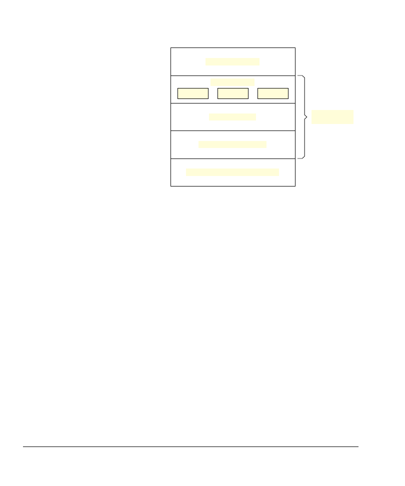
Figure 1-1 on page 1-6 shows the RL-USB software stack layers:
•
Device controller driver
•
USB core driver
•
Function driver.
The device controller driver is a hardware dependent layer. This layer is the interface
between the USB controller hardware and the USB core driver. The most important
function in the device controller driver is the interrupt service routine (
USB_ISR
), which
serves the USB interrupt generated by the USB controller. When the USB controller
hardware receives a data packet from the host or when the host requests data from the
device, the
USB_ISR
interrupt receives the requests. The interrupt function analyzes what
the interrupt is for and sends the appropriate event to the appropriate endpoint task (in
the USB core driver layer). The device controller driver also contains routines to read
and write to the USB controller’s hardware buffer (see Functions on page 1-47).
The USB core driver layer is a hardware independent layer. This layer contains the
functions that implement the USB requests sent by the host. This layer is an interface
between the device controller driver layer and the function driver layer. The most
important function in this layer is the
USB_EndPoint0
task. This function analyses all the
requests sent to endpoint
0
, such as the setup packets. This layer contains a separate task
for every endpoint that your application needs.
The function driver layer is also a hardware independent layer. This layer contains USB
class-specific functions. Therefore, the functions in this layer depends on the
application of your device. RL-USB provides function drivers for a number of classes:
•
Audio device
•
Human Interface Device (HID)
•
Mass storage device (MSC).
RL-USB
1-6
Copyright © 2007 ARM Limited. All rights reserved.
ARM DUI 0374A
Figure 1-1 RL-USB software stack
1.2.4
Using RL-USB
RL-USB is easy to use if your application belongs to one of the supported USB classes
and if you use one of the supported USB controllers. You must first determine which
USB controller and USB class you want to use. Find the corresponding example in the
installed folder (see Example Applications on page 1-7), and open it in
μVision. You
must then copy and modify the example source code to suit the requirements of your
application. The Configuration Wizard makes it easy to make modifications and
configure your application. See Creating New USB Applications on page 1-18 for more
detail.
'HYLFHFRQWUROOHUGULYHU
)XQFWLRQGULYHU
86%FRUHGULYHU
86%GHYLFHFRQWUROOHUKDUGZDUH
'HYLFHDSSOLFDWLRQ
+,'
06&
$XGLR
5/86%
VRIWZDUHVWDFN

RL-USB
ARM DUI 0374A
Copyright © 2007 ARM Limited. All rights reserved.
1-7
1.3
Example Applications
This section provides a list of all the examples in RL-USB, which demonstrate how to
interface to RL-USB in your applications. It describes how to run and test the various
example applications. It contains:
•
•
Running an audio example on page 1-8
•
Running an HID example on page 1-11
•
Running a mass storage device example on page 1-14.
1.3.1
List of examples
Each example in RL-USB is provided in the form of source code and is contained within
a separate folder. The folder also contains the
μVision project files. Therefore you can
quickly and easily build and test the examples.
Table 1-1 lists the different types of examples present in RL-USB.
Table 1-1 Types of examples
Example
Description
RTX_Audio
This example demonstrates how to implement USB communication
for an audio device. The application configures the evaluation board
as a sound card, which you can connect to a computer using a USB
cable.
RTX_HID
This example demonstrates how to implement USB communication
for an HID device. The application enables you to control the LEDs
of the evaluation board using an application that runs on the
computer.
RTX_Memory
This example demonstrates how to implement USB communication
for a mass storage device. The application configures the evaluation
board as a storage device to which you can copy files from the
computer.
RTX_Mouse
This example demonstrates how to implement USB communication
for a computer mouse device. The application configures the
evaluation board as a mouse that you can connect to the computer.
You can use the switches on the evaluation board to simulate the
mouse movement and clicks.

RL-USB
1-8
Copyright © 2007 ARM Limited. All rights reserved.
ARM DUI 0374A
RL-USB provides examples for each of the supported ARM-based USB controllers.
Table 1-2 shows the supported USB controllers, their source code location, and the
example applications they contain.
1.3.2
Running an audio example
This section describes how to build and run the audio example application on the
MCB2140 evaluation board. It contains:
•
•
Building and running the example on page 1-9.
Hardware requirements
To test this example, you require:
•
an MCB2140 evaluation board from Keil
•
a ULINK
®
USB to JTAG adapter from Keil
•
a standard USB cable (A-plug to B-plug).
Table 1-2 Folder structure
Controller
Folder
Examples
LPC214x
\ARM\Boards\Keil\MCB2140\RL\USB
RTX_HID, RTX_Memory, and
RTX_Audio for the MCB2140
™
evaluation board.
LPC23xx
\ARM\Boards\Keil\MCB2300\RL\USB
RTX_HID, RTX_Memory, and
RTX_Audio for the MCB2300
™
evaluation board.
STR75x
\ARM\Boards\Keil\MCBSTR750\RL\USB
RTX_HID and RTX_Memory for
the MCBSTR750
™
evaluation
board.
STR91x
\ARM\Boards\Keil\MCBSTR9\RL\USB
RTX_HID and RTX_Memory for
the MCBSTR9
™
evaluation board.
AT91SAM7S
xxx
\ARM\Boards\Atmel\AT91SAM7S-EK\RL
\USB
RTX_HID, RTX_Mouse, and
RTX_Memory for the
AT91SAM7S-EK
™
evaluation
board.

RL-USB
ARM DUI 0374A
Copyright © 2007 ARM Limited. All rights reserved.
1-9
Building and running the example
To build and run the example:
1.
Open the
Audio.Uv2
project in
\ARM\Boards\Keil\MCB2140\RL\USB\RTX_Audio
using
μVision.
2.
Select Project
→ Build target from the menu bar to build the example. The build
creates an executable file in the folder
\ARM\Boards\Keil\MCB2140\RL\USB\RTX_Audio\Obj
.
3.
Ensure that the MCB2140 board is configured for the ULINK
®
USB to JTAG
adapter (see the MCB2140 User’s Guide for the jumper settings). Connect the
ULINK adapter to the JTAG connector on the MCB2140 evaluation board and to
your computer using the USB cable. Power the MCB2140 evaluation board by
connecting it to the host computer using another USB cable.
4.
Select Flash
→ Download from the menu bar to download the executable file
into the flash device on the MCB2140 board. The board is now configured as a
sound card.
5.
Disconnect the USB cable (power) from the evaluation board for 10 seconds.
Then reconnect the USB cable. Windows might show a "Found New Hardware"
message to indicate that it recognizes the audio device. It then automatically loads
the correct host driver.
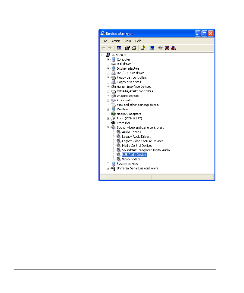
6.
You can check the status of this USB audio device in the Device Manager panel.
From the Control Panel, double click System. Select the Hardware tab. Then
select Device Manager. In the Sound, video and game controllers group (see
Figure 1-2 on page 1-10), double click USB Audio Device. This represents the
Keil MCB2140 speaker. Check that this device is enabled and working properly.
RL-USB
1-10
Copyright © 2007 ARM Limited. All rights reserved.
ARM DUI 0374A
Figure 1-2 USB audio device
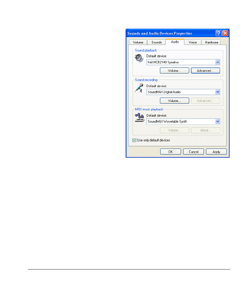
7.
Ensure that the Keil MCB2140 audio device is selected as the default playback
device. From the Control Panel, double click Sounds and Audio Devices. Select
the Audio tab. Ensure that Keil MCB2140 Speaker is selected as the default
Sound playback device (see Figure 1-3 on page 1-11).
RL-USB
ARM DUI 0374A
Copyright © 2007 ARM Limited. All rights reserved.
1-11
Figure 1-3 Select Keil MCB2140 as the default playback device
8.
You can now play any sound on the computer (for example using Windows Media
Player), and the Keil MCB2140 speaker produces the sound.
9.
You can adjust the volume using the Speaker Volume Control in Windows. Select
start
→ All Programs → Accessories → Entertainment → Volume Control.
10.
You can also control the volume using the POT1 potentiometer on the MCB2140
evaluation board. The LEDS on the evaluation board indicate the level of volume.
1.3.3
Running an HID example
This section describes how to build and run the Human Interface Device (HID) example
application on the MCBSTR9 evaluation board. It contains:
•
Hardware requirements on page 1-8
•

RL-USB
1-12
Copyright © 2007 ARM Limited. All rights reserved.
ARM DUI 0374A
Hardware requirements
To test this example, you require:
•
an MCBSTR9 evaluation board from Keil
•
a ULINK
®
USB to JTAG adapter from Keil
•
a standard USB cable (A-plug to B-plug).
Building and running the example
To build and run the example:
1.
Open the
HID.Uv2
project in
\ARM\Boards\Keil\MCBSTR9\RL\USB\RTX_HID
using
μVision.
2.
Select Project
→ Build target from the menu bar to build the example. The build
creates an executable file in the folder
\ARM\Boards\Keil\MCBSTR9\RL\USB\RTX_HID\Obj
.
3.
Ensure that the MCBSTR9 board is configured for the ULINK
®
USB to JTAG
adapter (see the MCBSTR9 User’s Guide for the jumper settings). Connect the
ULINK adapter to the JTAG connector on the MCBSTR9 evaluation board and to
your computer using the USB cable. Power the MCBSTR9 evaluation board by
connecting it to the host computer using another USB cable.
4.
Select Flash
→ Download from the menu bar to download the executable file
into the flash device on the MCBSTR9 board.
5.
Disconnect the USB cable (power) from the evaluation board for 10 seconds.
Then reconnect the USB cable. Windows might show a "Found New Hardware"
message to indicate that it recognizes the HID device. It then automatically loads
the correct host driver.
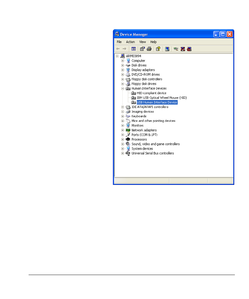
6.
You can check the status of this USB HID device in the Device Manager panel.
From the Control Panel, double click System. Select the Hardware tab. Then
select Device Manager. In the Human Interface Devices group (see Figure 1-4
on page 1-13), double click USB Human Interface Device. This represents the
Keil MCBSTR9 evaluation board. Check that this device is enabled and working
properly.
RL-USB
ARM DUI 0374A
Copyright © 2007 ARM Limited. All rights reserved.
1-13
Figure 1-4 USB human interface device
7.
You can now start the HIDClient.exe application in the folder
\ARM\Utilities\HID_Client1\Release
. In the HID Client application window,
select Keil MCBSTR9 HID from the device drop down menu. Figure 1-5 on
page 1-14 shows the HID client application.
RL-USB
1-14
Copyright © 2007 ARM Limited. All rights reserved.
ARM DUI 0374A
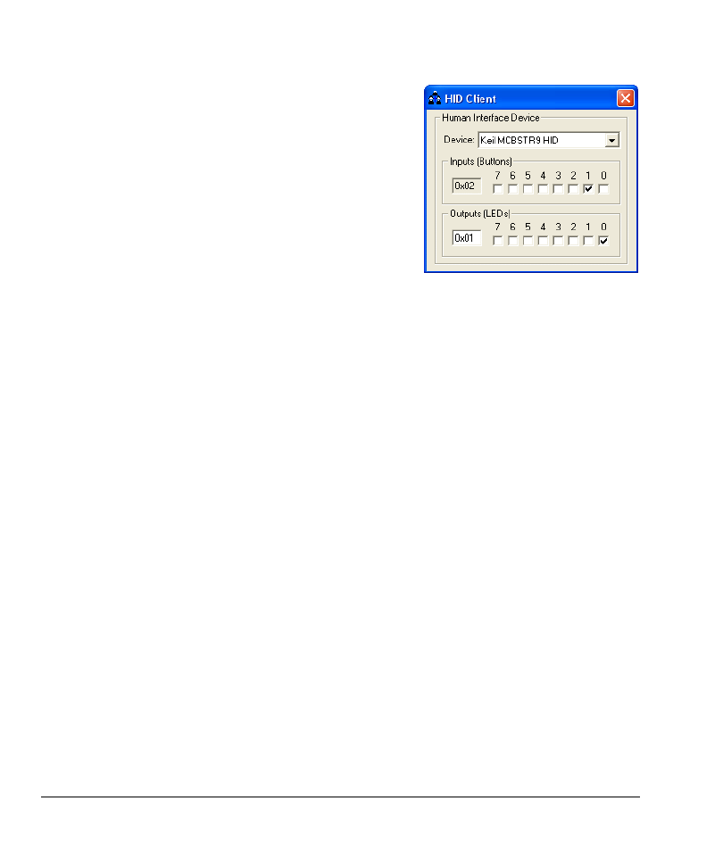
Figure 1-5 HID client application
8.
Select the Outputs (LEDs) box 0 and check that the corresponding LED on the
board turns on. Press and hold the INT6 button on the board and check that the
Inputs (Buttons) box 1 is selected in the HID Client. You can control the state of
the LEDs using the HID Client. You can also use the HID client to read the state
of the buttons on the evaluation board.
1.3.4
Running a mass storage device example
This section describes how to build and run the mass storage device example application
on the MCB2140 evaluation board. It contains:
•
Hardware requirements on page 1-8
•
Building and running the example on page 1-9.
Hardware requirements
To test this example, you require:
•
an MCB2140 evaluation board from Keil
•
a ULINK
®
USB to JTAG adapter from Keil
•
a standard USB cable (A-plug to B-plug).
Building and running the example
To build and run the example:
1.
Open the
Memory.Uv2
project in
\ARM\Boards\Keil\MCB2140\RL\USB\RTX_Memory
using
μVision.

RL-USB
ARM DUI 0374A
Copyright © 2007 ARM Limited. All rights reserved.
1-15
2.
Select Project
→ Build target from the menu bar to build the example. The build
creates an executable file in the folder
\ARM\Boards\Keil\MCB2140\RL\USB\RTX_Memory\Obj
.
3.
Ensure that the MCB2140 board is configured for the ULINK
®
USB to JTAG
adapter (see the MCB2140 User’s Guide for the jumper settings). Connect the
ULINK adapter to the JTAG connector on the MCB2140 evaluation board and to
your computer using the USB cable. Power the MCB2140 evaluation board by
connecting it to the host computer using another USB cable.
4.
Select Flash
→ Download from the menu bar to download the executable file
into the flash device on the MCB2140 board.
5.
Disconnect the USB cable (power) from the evaluation board for 10 seconds.
Then reconnect the USB cable. Windows might show a "Found New Hardware"
message to indicate that it recognizes the audio device. It then automatically loads
the correct host driver.
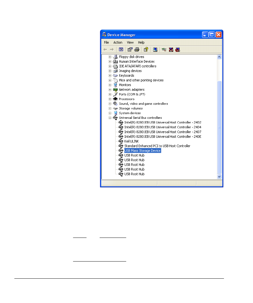
6.
You can check the status of this USB mass storage device in the Device Manager
panel. From the Control Panel, double click System. Select the Hardware tab.
Then select Device Manager. In the Universal Serial Bus controllers group (see
Figure 1-6 on page 1-16), double click USB Mass Storage Device. This
represents the Keil MCB2140 board. Check that this device is enabled and
working properly.
RL-USB
1-16
Copyright © 2007 ARM Limited. All rights reserved.
ARM DUI 0374A
Figure 1-6 USB mass storage device
7.
You can now open Windows File Explorer and find the removable disk named
LPC2148 USB.
8.
Open the file
README.TXT
from the USB storage device. Modify this file and save
it back to the USB storage device using a different filename. You can transfer files
between the USB storage device and your host computer.
Note
The MCB2140 board provides only 16 kB of storage space, which is part of the
LPC2148 microcontroller’s onboard RAM. Therefore it loses its contents if the
board loses power.

RL-USB
ARM DUI 0374A
Copyright © 2007 ARM Limited. All rights reserved.
1-17
9.
The LEDs on the MCB2140 board show the mass storage device activities:
•
LED P1.16 turns on when the USB device is performing read access.
•
LED P1.17 turns on when the USB device is performing write access.
•
LED P1.22 turns on when the USB device is configured.
•
LED P1.23 turns on when the USB device is suspended.

RL-USB
1-18
Copyright © 2007 ARM Limited. All rights reserved.
ARM DUI 0374A
1.4
Creating New USB Applications
This section describes the steps involved in adding the USB interface to your new or
existing applications. It describes the changes you must make to the RL-USB software
stack to integrate it safely into your application. It contains:
•
Creating a new HID application
•
Creating a new audio application on page 1-22
•
Creating a new mass storage application on page 1-25
•
Creating a new composite device application on page 1-28.
1.4.1
Creating a new HID application
This section describes the changes you must make to RL-USB to integrate it into an
HID application. It contains:
•
•
Adding an OUT pipe to an existing HID application on page 1-20.
Using the RL-USB HID template
You can use the HID template to create applications for mice, keyboards, or other
control devices. This section describes how to use one of the provided HID examples as
a template to add USB communication to your application:
1.
RL-USB supports several USB controllers (see List of examples on page 1-7). In
the installed folder
\ARM\Boards
, identify the USB controller that your application
uses. You must use the HID example in this
\ARM\Boards\…\…\RL\USB
folder as a
template.
2.
Copy all the source files (
*.c
and
*.s
) and header files (
*.h
) from the RTX_HID
example folder into your existing or new application folder. If you are creating a
new application, also copy the project file
HID.Uv
2 file from the example folder.
3.
Open your project using
μVision. If your application is an already existing
project, then add all the new
*.c
source files to your project using the Add Files
to Group option in
μVision.
4.
Now you can configure the RL-USB software stack as required by your
application (see Configuration Parameters on page 1-34). For example in
usbcfg.h
:
•
enable the events you want to handle (you must provide the event handling
code in
usbuser.c
)
•
ensure that the define
USB_HID
is set to 1.

RL-USB
ARM DUI 0374A
Copyright © 2007 ARM Limited. All rights reserved.
1-19
5.
The RL-USB HID example has a simple function which requires it to send and
receive one byte of data (representing LEDs and buttons) from the host computer.
You can modify it to suit the requirements of your application (see the USB
Device Class Definition for Human Interface Devices (HID) specification for
more information):
•
If your application has to send or receive more data, or if your application
has to represent the data differently, you must modify:
—
usbdesc.
c (to modify the report descriptor,
HID_ReportDescriptor
, and
the endpoint’s
wMaxPacketSize
field of the configuration descriptor)
—
demo.c
(to enlarge the buffer
InReport
or
OutReport
, as required, to
store the largest data packet,
wMaxPacketSize
, of the endpoint you use)
—
hiduser.c
(to modify
HID_GetReport
and
HID_SetReport
to copy all the
data from the host or to write all the data to the endpoint
0
buffer
(
EP0Buf
), depending on the endpoint
0
maximum packet size).
•
If you want to use an additional endpoint, you must modify:
—
usbuser.c
(to provide the appropriate
USB_EndPoint<Number>
function
to read or write to the endpoint buffer)
—
usbcfg.h
(to activate the necessary endpoints using the define
USB_EP_EVENT
)
—
usbdesc.c
(to define the endpoint descriptor and modify the fields
bNumEndpoints
and
wTotalLength
in the configuration descriptor).
You must also modify
demo.c
(
SetOutReport
and
GetInReport
functions) or provide
your own main application module to generate the data required by the host or to
use all the data from the host.
6.
In the string descriptor (
USB_StringDescriptor
), in
usbdesc.c
, you can modify the
labels for:
•
manufacturer name
•
product name
•
serial number of the product
•
interface name.
If you change the length of any of these strings, then you must also modify the
corresponding
bLength
field, in the string descriptor, to show the new length.
7.
In the configuration descriptor (
USB_ConfigDescriptor
), in
usbdesc.c
, you can
modify certain settings to suit your product:
•
If your device is self powered, you must change the value of the field
bmAttributes
to
USB_CONFIG_SELF_POWERED|USB_CONFIG_POWERED_MASK
. You
can also use
|USB_CONFIG_REMOTE_WAKEUP
if you want the host to control
when your device can use the remote wakeup feature.

RL-USB
1-20
Copyright © 2007 ARM Limited. All rights reserved.
ARM DUI 0374A
•
You can modify the maximum power requirement (field
bMaxPower
).
•
You must modify the index of the interface string (field
iInterface
) if you
modify the string descriptor (
USB_StringDescriptor
).
•
You can optionally modify the country code (field
bCountryCode
).
See the USB Specification for more information on what each field in the
descriptor means and what requirements that imposes on your application.
8.
In the device descriptor (
USB_DeviceDescriptor
), in
usbdesc.c
, you can modify
certain settings to suit your product:
•
If you modify the string descriptor, you must also modify the indices of the
manufacturer name string (field
iManufacturer
), product name string (field
iProduct
), and serial number string (field
iSerialNumber
).
•
You can modify the vendor ID (field
idVendor
), product ID (field
idProduct
), and device release number (field
bcdDevice
).
9.
Select Project
→ Options for Target from the menu bar to display the build
options. In the Target tab of the build options, select RTX Kernel for the
Operating system. Build your application and run it on the target hardware (see
Running an HID example on page 1-11).
10.
Windows 2000 and later versions provide USB host controller drivers that is
sufficient for applications that use the existing features of RL-USB. If Windows
does not support the functionality you add to RL-USB, then you must also
provide your own host controller driver. Also, depending on your application, you
might have to develop a host side application, using the Windows Driver
Development Kit, to communicate with your USB device.
Adding an OUT pipe to an existing HID application
The HID example in RL-USB uses endpoint
0
and endpoint
1
. However, endpoint
1
only
implements the IN pipe. This means that it only transfers data from the device to the
host. This section describes the changes you must make to implement an OUT pipe
using endpoint
1
so that you can use endpoint
1
to transfer data from the host to the
device. You must make changes to the files
usbdesc.c
and
usbuser.c
from the provided
HID example application:
1.
Open one of provided HID examples in
μVision.
2.
In the configuration descriptor (
USB_ConfigDescriptor
), in
usbdesc.c
, add a new
endpoint descriptor after the end of the existing endpoint descriptor. The new
endpoint descriptor describes the OUT pipe for endpoint
1
.

RL-USB
ARM DUI 0374A
Copyright © 2007 ARM Limited. All rights reserved.
1-21
const U8 USB_ConfigDescriptor[] =
{
…
/* End of endpoint 1 IN pipe descriptor */
/* Begin endpoint 1, OUT pipe descriptor */
USB_ENDPOINT_DESC_SIZE,
// bLength
USB_ENDPOINT_DESCRIPTOR_TYPE, // bDescriptorType
USB_ENDPOINT_OUT(1),
// bEndpointAddress
USB_ENDPOINT_TYPE_INTERRUPT,
// bmAttributes = interrupt transfer
WBVAL(0x0040),
// wMaxPacketSize = 64 bytes
0x20,
// bInterval = 32 ms
/* End of endpoint 1 OUT pipe descriptor */
/* Terminator */
0
}
3.
In the configuration descriptor:
•
increase the number of endpoints (field
bNumEndpoints
) to
0x02
•
increase the total length of the configuration descriptor (field
wTotalLength
)
by
USB_ENDPOINT_DESC_SIZE
.
WBVAL( //
wTotalLength
USB_CONFIGUARTION_DESC_SIZE +
USB_INTERFACE_DESC_SIZE +
HID_DESC_SIZE +
USB_ENDPOINT_DESC_SIZE * 2
),
4.
Modify the
USB_EndPoint1
function in
usbuser.c
to handle the event
USB_EVT_OUT
.
void USB_EndPoint1 (void) __task
{
U16 evt;
for (;;)
{
/* Wait for IN or OUT signal from the host */
os_evt_wait_or(USB_EVT_IN | USB_EVT_OUT, 0xFFFF);
evt = os_evt_get(); /* Get the current event */
if (evt = USB_EVT_IN)
{
/* Function to update or obtain the data (InReport) that needs to be
sent to the host */
GetInReport();
/* Write 1 byte to the endpoint IN pipe */
USB_WriteEP(0x81, &InReport, sizeof(InReport));
}
else /* evt = USB_EVT_OUT */
{
/* Read one byte from the endpoint OUT pipe */
USB_ReadEP (0x01, &OutReport);
/* Function to use the read data (OutReport) as needed by your

RL-USB
1-22
Copyright © 2007 ARM Limited. All rights reserved.
ARM DUI 0374A
application. */
SetOutReport();
}
}
}
5.
Build and run the application on the target board to verify that it works. See
Running an HID example on page 1-11 for more information.
1.4.2
Creating a new audio application
This section describes the changes you must make to RL-USB to integrate it into an
audio application. It contains:
•
Using the RL-USB audio template.
Using the RL-USB audio template
You can use the audio template to create applications for speakers, microphones, or
other audio devices. This section describes how to use one of the provided audio
examples as a template to add USB communication to your audio application:
1.
RL-USB supports several USB controllers (see List of examples on page 1-7). In
the installed folder
\ARM\Boards
, identify the USB controller that your application
uses. You must use the audio example in this
\ARM\Boards\…\…\RL\USB
folder as a
template.
2.
Copy all the source files (
*.c
and
*.s
) and header files (
*.h
) from the RTX_Audio
example folder into your existing or new application folder. If you are creating a
new application, also copy the project file
Audio.Uv
2 file from the example folder.
If there is no audio example for your USB controller, then you can use the source
files from one of the other examples in the same USB controller folder. However,
you must copy the class dependent files from the audio example of another USB
controller:
•
usbdesc.c
•
adcuser.c
•
usbuser.c
•
demo.c
•
usbdesc.h
•
adcuser.h
•
audio.h
•
demo.h.
These source files might contain hardware dependent code, which you must
modify to suit your USB controller.

RL-USB
ARM DUI 0374A
Copyright © 2007 ARM Limited. All rights reserved.
1-23
3.
Open your project using
μVision. If your application is an already existing
project, then add all the new
*.c
source files to your project using the Add Files
to Group option in
μVision.
4.
Now you can configure the RL-USB software stack as required by your
application (see Configuration Parameters on page 1-34). For example in
usbcfg.h
:
•
enable the events you want to handle (you must provide the event handling
code in
usbuser.c
)
•
ensure that the define
USB_AUDIO
is set to 1.
5.
The RL-USB audio example has a simple function which enables it to receive a
stream of audio data from the host and send it to a speaker. You can modify it for
your application’s requirements (see the USB Device Class Definition for Audio
Devices specification for more information):
a.
If you want to use an additional AudioStreaming interface to stream
different audio data or format, either from the host to the device or from the
device to the host, you must modify:
•
usbuser.c
(to provide the appropriate
USB_EndPoint<Number>
function
and to handle the SOF event)
•
usbcfg.h
(to activate the necessary endpoints using the define
USB_EP_EVENT
)
•
usbdesc.c
(to define the AudioStreaming descriptor and modify fields
bNumInterfaces
and
wTotalLength
in the configuration descriptor).
Use the existing functionality in the files as a template for your
modifications. You must also modify
demo.c
or provide your main
application module.
b.
If you want to extend the AudioControl interface with more units or
features, you must modify:
•
adcuser.c
(to handle the additional class specific requests in the
ADC_IF_SetRequest
and
ADC_IF_GetRequest
functions)
•
usbdesc.c
(to define the interfaces for the additional units in the
configuration descriptor).
Use the existing functionality in the files as a template for your
modifications. You must also modify
demo.c
or provide your main
application module.
Note
•
The audio example in RL-USB provides one AudioControl interface
consisting of:
—
Input Terminal
—
Output Terminal

RL-USB
1-24
Copyright © 2007 ARM Limited. All rights reserved.
ARM DUI 0374A
—
Feature Unit consisting of mute and volume features.
•
The AudioControl interface in the example is a collection of one
AudioStreaming interface. The AudioStreaming interface has a zero
bandwidth alternate setting and a general format (PCM) streaming
interface.
6.
In the string descriptor (
USB_StringDescriptor
), in
usbdesc.c
, you can modify the
labels for:
•
manufacturer name
•
product name
•
serial number of the product
•
interface name.
If you change the length of any of these strings, then you must also modify the
corresponding
bLength
field, in the string descriptor, to show the new length.
7.
In the configuration descriptor (
USB_ConfigDescriptor
), in
usbdesc.c
, you can
modify certain settings to suit your product:
•
If your device is self powered, you must change the value of the field
bmAttributes
to
USB_CONFIG_SELF_POWERED|USB_CONFIG_POWERED_MASK
. You
can also use
|USB_CONFIG_REMOTE_WAKEUP
if you want the host to control
when your device can use the remote wakeup feature.
•
You can modify the maximum power requirement (field
bMaxPower
).
•
You must modify the index of the interface string (field
iInterface
) if you
modify the string descriptor (
USB_StringDescriptor
).
See the USB Specification for more information on what each field in the
descriptor means and what requirements that imposes on your application.
8.
In the device descriptor (
USB_DeviceDescriptor
), in
usbdesc.c
, you can modify
certain settings to suit your product:
•
If you modify the string descriptor, you must also modify the indices of
manufacturer name string (field
iManufacturer
), product name string (field
iProduct
), and serial number string (field
iSerialNumber
).
•
You can modify the vendor ID (field
idVendor
), product ID (field
idProduct
), and device release number (field
bcdDevice
).
9.
Select Project
→ Options for Target from the menu bar to display the build
options. In the Target tab of the build options, select RTX Kernel for the
Operating system. Build your application and run it on the target hardware (see
Running an audio example on page 1-8).

RL-USB
ARM DUI 0374A
Copyright © 2007 ARM Limited. All rights reserved.
1-25
10.
Windows 2000 and later versions provide USB host controller drivers that is
sufficient for applications that use the existing features of RL-USB. If Windows
does not support the functionality you add to RL-USB, then you must also
provide your own host controller driver. Also, depending on your application, you
might have to develop a host side application, using the Windows Driver
Development Kit, to communicate with your USB device.
1.4.3
Creating a new mass storage application
This section describes the changes you must make to RL-USB to integrate it into a mass
storage application. It contains:
•
Using the RL-USB MSC template.
Using the RL-USB MSC template
You can use the MSC template to create applications for USB sticks, cameras, or other
external storage devices. This section describes how to use one of the provided memory
examples as a template to add USB communication to your mass storage application:
1.
RL-USB supports several USB controllers (see List of examples on page 1-7). In
the installed folder
\ARM\Boards
, identify the USB controller that your application
uses. You must use the memory example in this
\ARM\Boards\…\…\RL\USB
folder as
a template.
2.
Copy all the source files (
*.c
and
*.s
) and header files (
*.h
) from the
RTX_Memory example folder into your existing or new application folder. If you
are creating a new application, also copy the project file
Memory.Uv
2 file from the
example folder.
3.
Open your project using
μVision. If your application is an already existing
project, then add all the new
*.c
source files to your project using the Add Files
to Group option in
μVision.
4.
Now you can configure the RL-USB software stack as required by your
application (see Configuration Parameters on page 1-34). For example in
usbcfg.h
:
•
enable the events you want to handle (you must provide the event handling
code in
usbuser.c
)
•
ensure that the define
USB_MSC
is set to 1.

RL-USB
1-26
Copyright © 2007 ARM Limited. All rights reserved.
ARM DUI 0374A
5.
The RL-USB memory example has a simple function which enables you to
transfer files to and from the host computer and the device’s onboard RAM. You
can modify it for your application’s requirements (see the USB Mass Storage
Class Bulk-Only Transport specification for more information):
•
If you want to add alternate interfaces or endpoints, you must modify:
—
usbuser.c
(to provide the appropriate
USB_EndPoint<Number>
functions)
—
usbcfg.h
(to activate the necessary endpoints using the define
USB_EP_EVENT
)
—
usbdesc.c
(to define the interface or endpoint descriptors and modify
the fields
bNumInterfaces
,
bNumEndpoints
and
wTotalLength
in the
configuration descriptor)
—
mscuser.c
(to obtain and use the data from the new endpoints as
needed).
Use the existing functionality in the files as a template for your
modifications. You must also modify
memory.c
or provide your main
application module.
•
If you want to use a different mass storage medium (rather than the onboard
RAM), you must modify the functions
MSC_MemoryRead
,
MSC_MemoryWrite
,
and
MSC_MemoryVerify
in
mscuser.c
.
•
Modify the function
MSC_Inquiry
in
mscuser.c
to show your vendor ID,
product ID, and product revision level.
•
In
mscuser.h
, you can reduce the value of the define
MSC_MAX_PACKET
to a
lower power of 2 if you want to reduce RAM usage. Ensure that the same
value is used in the endpoint descriptors (field
wMaxPacketSize
), in the
configuration descriptor, in
usbdesc.c
.
•
In
mscuser.h
, you must change the value of the define
MSC_MemorySize
to
show the number of bytes available in your mass storage medium.
Note
The Windows default driver only supports the SCSI subclass for mass storage
applications. This supports flash drives and hard disk drives. If your application
uses a different storage medium, then you must change the subclass code (field
bInterfaceSubClass
) in the configuration descriptor and provide the required
protocol commands in mscuser.c. You must also provide your own USB host
controller driver in this case.
6.
In the string descriptor (
USB_StringDescriptor
), in
usbdesc.c
, you can modify the
labels for:
•
manufacturer name
•
product name

RL-USB
ARM DUI 0374A
Copyright © 2007 ARM Limited. All rights reserved.
1-27
•
serial number of the product
•
interface name.
If you change the length of either of these strings, then you must also modify the
corresponding
bLength
field, in the string descriptor, to show the new length.
7.
In the configuration descriptor (
USB_ConfigDescriptor
), in
usbdesc.c
, you can
modify certain settings to suit your product:
•
If your device is self powered, you must change the value of the field
bmAttributes
to
USB_CONFIG_SELF_POWERED|USB_CONFIG_POWERED_MASK
. You
can also use
|USB_CONFIG_REMOTE_WAKEUP
if you want the host to control
when your device can use the remote wakeup feature.
•
You can modify the maximum power requirement (field
bMaxPower
).
•
You must modify the index of the interface string (field
iInterface
) if you
modify the string descriptor (
USB_StringDescriptor
).
See the USB Specification for more information on what each field in the
descriptor means and what requirements that imposes on your application.
8.
In the device descriptor (
USB_DeviceDescriptor
), in
usbdesc.c
, you can modify
certain settings to suit your product:
•
If you modify the string descriptor, you must also modify the indices of
manufacturer name string (field
iManufacturer
), product name string (field
iProduct
), and serial number string (field
iSerialNumber
).
•
You can modify the vendor ID (field
idVendor
), product ID (field
idProduct
), and device release number (field
bcdDevice
).
9.
Select Project
→ Options for Target from the menu bar to display the build
options. In the Target tab of the build options, select RTX Kernel for the
Operating system. Build your application and run it on the target hardware (see
Running a mass storage device example on page 1-14).
10.
Windows 2000 and later versions provide USB host controller drivers that is
sufficient for applications that use the existing features of RL-USB. If Windows
does not support the functionality you add to RL-USB, then you must also
provide your own host controller driver. Also, depending on your application, you
might have to develop a host side application, using the Windows Driver
Development Kit, to communicate with your USB device.

RL-USB
1-28
Copyright © 2007 ARM Limited. All rights reserved.
ARM DUI 0374A
1.4.4
Creating a new composite device application
This section describes the how to create a composite device application that uses the
HID, audio, and mass storage classes in one configuration. You can use this approach
to create a device using any combination of the classes:
1.
RL-USB supports several USB controllers (see List of examples on page 1-7). In
the installed folder
\ARM\Boards
, identify the USB controller that your application
uses. You must use the examples in this
\ARM\Boards\…\…\RL\USB
folder as the
templates.
2.
Copy all the source files (
*.c
and
*.s
) and header files (
*.h
) from the RTX_HID,
RTX_Audio, and RTX_Memory example folders into your existing or new
application folder. You can overwrite the files that have the same name. If there is
no audio example for your USB controller, then you must copy the audio class
dependent files from the audio example of another USB controller (see Using the
RL-USB audio template on page 1-22).
3.
Using a prefix to identify the files, copy and rename the files
demo.c
,
demo.h
,
usbuser.c
,
usbdesc.c
, and
usbdesc.h
from each class into your application folder.
For example copy the file
usbdesc.c
from the RTX_HID example and rename it
to
hid_usbdesc.c
in your application folder.
4.
Merge the unique contents of the different
prefix_usbdesc.h
files into a single file
called
usbdesc.h
5.
Rename one of the
prefix_usbdesc.c
files to
usbdesc.c
. From the remaining
prefix_usbdesc.c
files, copy the unique section of code representing the
interfaces and endpoints in the configuration descriptor (
USB_ConfigDescriptor
),
and paste the contents one after the other at the end of the configuration
descriptor, in
usbdesc.c
, before the null terminator field. For example in the
RTX_Memory example’s
usbdesc.c
file, the interface and endpoint descriptors
that you must copy are located between the field
bMaxPower
and the null
terminator:
/* Interface 0, Alternate Setting 0, MSC Class */
USB_INTERFACE_DESC_SIZE,
/* bLength */
USB_INTERFACE_DESCRIPTOR_TYPE,
/* bDescriptorType */
0x00,
/* bInterfaceNumber */
0x00,
/* bAlternateSetting */
0x02,
/* bNumEndpoints */
USB_DEVICE_CLASS_STORAGE,
/* bInterfaceClass */
MSC_SUBCLASS_SCSI,
/* bInterfaceSubClass */
MSC_PROTOCOL_BULK_ONLY,
/* bInterfaceProtocol */
0x62,
/* iInterface */
/* Bulk In Endpoint */
USB_ENDPOINT_DESC_SIZE,
/* bLength */
USB_ENDPOINT_DESCRIPTOR_TYPE,
/* bDescriptorType */

RL-USB
ARM DUI 0374A
Copyright © 2007 ARM Limited. All rights reserved.
1-29
USB_ENDPOINT_IN(2),
/* bEndpointAddress */
USB_ENDPOINT_TYPE_BULK,
/* bmAttributes */
WBVAL(MSC_MAX_PACKET),
/* wMaxPacketSize */
0,
/* bInterval */
/* Bulk Out Endpoint */
USB_ENDPOINT_DESC_SIZE,
/* bLength */
USB_ENDPOINT_DESCRIPTOR_TYPE,
/* bDescriptorType */
USB_ENDPOINT_OUT(2),
/* bEndpointAddress */
USB_ENDPOINT_TYPE_BULK,
/* bmAttributes */
WBVAL(MSC_MAX_PACKET),
/* wMaxPacketSize */
0,
/* bInterval */
Ensure you include the files
audio.h
,
msc.h
, and
hid.h
using
#include
in
usbdesc.c
. You can delete the other
prefix_usbdesc.c
and
prefix_usbdesc.h
files.
6.
You must modify the configuration descriptor (
USB_ConfigDescriptor
) in
usbdesc.c:
•
Give each interface a unique interface number (field
bInterfaceNumber
)
starting from
0.
•
Change the field
bNumInterfaces
to correspond to the number of interfaces
in the application. In this example, there are 4 interfaces:
—
HID interface
—
AudioControl interface
—
AudioStreaming interface
—
Mass storage interface.
•
Modify the field
wTotalLength
to reflect the total length of the configuration
descriptor. In this example, set the value to:
WBVAL(
/* wTotalLength */
USB_CONFIGUARTION_DESC_SIZE +
USB_INTERFACE_DESC_SIZE +
AUDIO_CONTROL_INTERFACE_DESC_SZ(1) +
AUDIO_INPUT_TERMINAL_DESC_SIZE +
AUDIO_FEATURE_UNIT_DESC_SZ(1,1) +
AUDIO_OUTPUT_TERMINAL_DESC_SIZE +
USB_INTERFACE_DESC_SIZE +
USB_INTERFACE_DESC_SIZE +
AUDIO_STREAMING_INTERFACE_DESC_SIZE +
AUDIO_FORMAT_TYPE_I_DESC_SZ(1) +
AUDIO_STANDARD_ENDPOINT_DESC_SIZE +
AUDIO_STREAMING_ENDPOINT_DESC_SIZE
+
1*USB_INTERFACE_DESC_SIZE
+
2*USB_ENDPOINT_DESC_SIZE
+
USB_INTERFACE_DESC_SIZE +
HID_DESC_SIZE +
USB_ENDPOINT_DESC_SIZE
)

RL-USB
1-30
Copyright © 2007 ARM Limited. All rights reserved.
ARM DUI 0374A
See the USB Specification for more information on the descriptors.
7.
Now you can configure the RL-USB software stack as required by your
application using the Configuration Wizard (see Configuration Parameters on
page 1-34). For example in
usbcfg.h
:
•
Enable the events you want to handle (you must provide the event handling
code in
usbuser.c
)
•
Ensure that the defines
USB_HID
,
USB_AUDIO
, and
USB_MSC
are set to
1
.
•
Ensure that the define
USB_IF_NUM
supports the number of interfaces in the
application. In this example, ensure that the value is
4
or more.
•
Activate the necessary endpoints using the define
USB_EP_EVENT
. In this
example, set the value to
0x000F
because the example composite device uses
the first 4 endpoints.
•
Assign unique values to the defines that number the interfaces. Ensure that
this value matches with the interface number (field
bInterfaceNumber
) you
give in the configuration descriptor (
usbdesc.c
). For example:
#define USB_HID_IF_NUM
0
#define USB_MSC_IF_NUM
1
#define USB_ADC_CIF_NUM
2
#define USB_ADC_SIF1_NUM 3
#define USB_ADC_SIF2_NUM 4
To avoid a clash in endpoint numbers, each of the individual examples uses a
different endpoint number for its interface. Therefore you do not have to change
the endpoint numbers in the configuration descriptor.
8.
Rename one of the
prefix_usbuser.c
files to
usbuser.c
. In the file usbuser.c, you
must provide the functions to handle:
•
endpoint events
•
USB device events
•
USB core events.
You can copy these functions from the remaining
prefix_usbuser.c
files. In
particular, copy:
•
function
USB_EndPoint1
from RTX_HID example’s
usbuser.c
•
function
USB_EndPoint2
from RTX_Memory example’s
usbuser.c
•
function
USB_EndPoint3
from RTX_Audio example’s
usbuser.c
•
handling of the event
USB_EVT_SOF
(function
USB_Device)
from RTX_Audio
example’s
usbuser.c
.

RL-USB
ARM DUI 0374A
Copyright © 2007 ARM Limited. All rights reserved.
1-31
You can provide your own code to handle the other device and core events (see
Configuration Parameters on page 1-34). Ensure that
usbuser.c
includes the file
mscuser.h
using
#include
. When you have copied the necessary code sections into
usbuser.c
, you can delete the remaining
prefix_usbuser.c
files.
9.
Merge
memory.c
and both
prefix_demo.c
files to create a single main application
file called
demo.c
:
•
Rename one of the
prefix_demo.c
files to
demo.c
.
•
Copy the unique contents from the second
prefix_demo.c
and
memory.c
files
to
demo.c
. This includes unique global variables and functions.
•
Merge the unique contents from the functions
demo
(RTX_Audio and
RTX_HID examples) and
memory
(RTX_memory example).
You can now delete the files
prefix_demo.c
and
memory.c
.
10.
Merge the unique contents of the application header files
memory.h
and both
prefix_demo.h
to create a single main application header file with the name
demo.h
. Ensure that this header file is included in
usbuser.c
and in the main
application file
demo.c
. You can now delete the files
memory.h
and
prefix_demo.h
.
Note
Do
not
include
memory.h
in the files
usbuser.c
and
demo.c
.
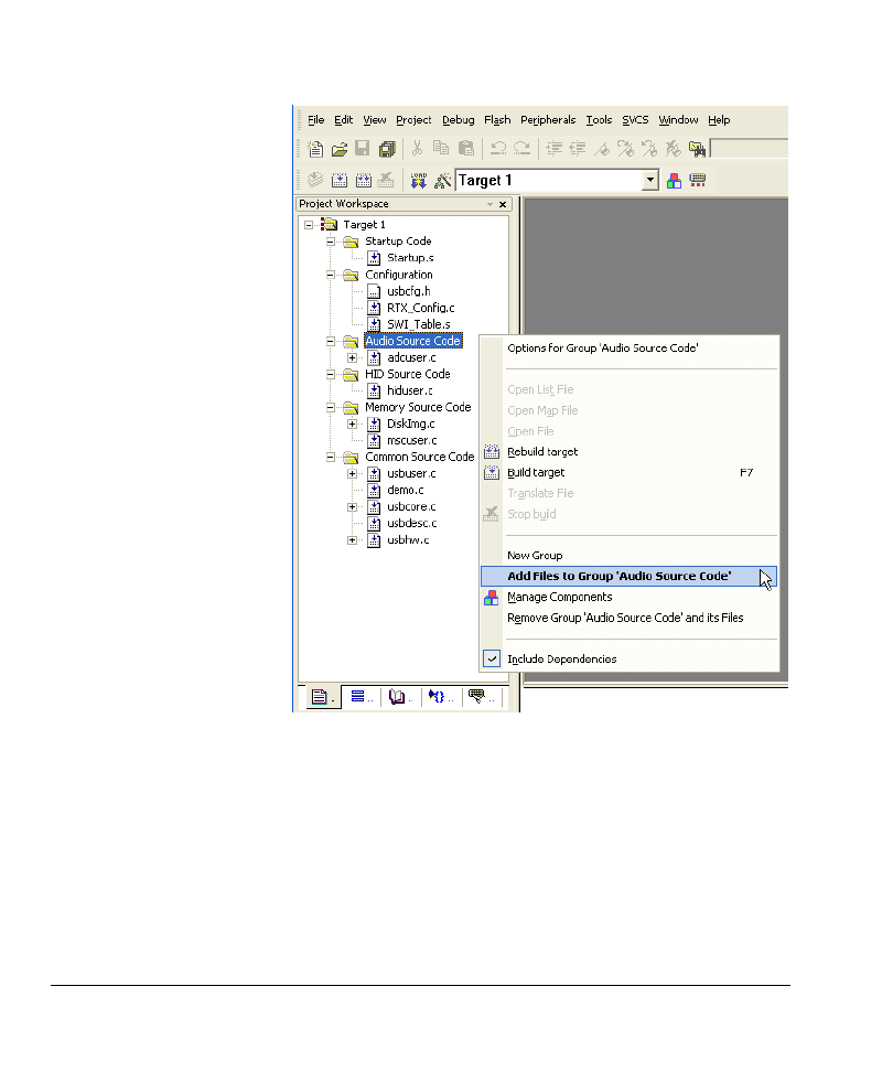
11.
You now have the complete set of source files in your application folder. Create a
new application in
μVision or open your existing project using μVision. Then add
all the new
*.c
source files to your project using the Add Files to Group option
in
μVision (see Figure 1-7 on page 1-32).
RL-USB
1-32
Copyright © 2007 ARM Limited. All rights reserved.
ARM DUI 0374A
Figure 1-7 Add source files for composite device
12.
In the string descriptor (
USB_StringDescriptor
), in
usbdesc.c
, you can modify the
labels for:
•
manufacturer name
•
product name
•
serial number of the product
•
interface name.
If you change the length of any of these strings, then you must also modify the
corresponding
bLength
field, in the string descriptor, to show the new length.

RL-USB
ARM DUI 0374A
Copyright © 2007 ARM Limited. All rights reserved.
1-33
13.
In the configuration descriptor (
USB_ConfigDescriptor
), in
usbdesc.c
, you can
modify certain settings to suit your product:
•
If your device is self powered, you must change the value of the field
bmAttributes
to
USB_CONFIG_SELF_POWERED|USB_CONFIG_POWERED_MASK
. You
can also use
|USB_CONFIG_REMOTE_WAKEUP
if you want the host to control
when your device can use the remote wakeup feature.
•
You can modify the maximum power requirement (field
bMaxPower
).
•
You must modify the index of the interface string (field
iInterface
) if you
modify the string descriptor (
USB_StringDescriptor
).
See the USB Specification for more information on what each field in the
descriptor means and what requirements that imposes on your application.
14.
In the device descriptor (
USB_DeviceDescriptor
), in
usbdesc.c
, you can modify
certain settings to suit your product:
•
If you modify the string descriptor, you must also modify the indices of
manufacturer name string (field
iManufacturer
), product name string (field
iProduct
), and serial number string (field
iSerialNumber
).
•
You can modify the vendor ID (field
idVendor
), product ID (field
idProduct
), and device release number (field
bcdDevice
).
15.
Select Project
→ Options for Target from the menu bar to display the build
options. In the Target tab of the build options, select RTX Kernel for the
Operating system. Build your application and run it on the target hardware (see
Running a mass storage device example on page 1-14).
16.
Windows 2000 and later versions provide USB host controller drivers that is
sufficient for applications that use the existing features of RL-USB. If Windows
does not support the functionality you add to RL-USB, then you must also
provide your own host controller driver. Also, depending on your application, you
might have to develop a host side application, using the Windows Driver
Development Kit, to communicate with your USB device.

RL-USB
1-34
Copyright © 2007 ARM Limited. All rights reserved.
ARM DUI 0374A
1.5
Configuration Parameters
This section describes how to configure RL-USB for your product. It contains:
•
Using the Configuration Wizard
•
USB Configuration on page 1-35
•
USB Event Handlers on page 1-38
•
USB Class Support on page 1-41.
1.5.1
Using the Configuration Wizard
μVision provides an easy-to-use interface to configure the RL-USB for your product
requirements. This is called the Configuration Wizard interface, and you can use it to
configure all the parameters present in the configuration file
usbcfg.h
. To access the
Configuration Wizard, open the
usbcfg.h
file in
μVision, and then click on the
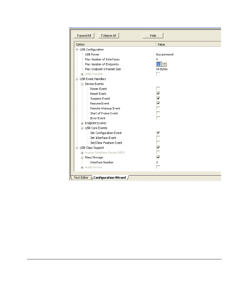
Configuration Wizard tab. Figure 1-8 on page 1-35 shows the Configuration Wizard
interface. In the Configuration Wizard interface, you can select the events you want to
use in your application, and you can set the values of the other defines that are present
in
usbcfg.h
.
The configurable parameters in the Configuration Wizard are categorized into:
•
USB Configuration on page 1-35
This contains product, application, and controller specific configuration.
•
USB Event Handlers on page 1-38
This enables you to select the events that your application requires notification
about.
•
USB Class Support on page 1-41
This makes it easy for you to enable class specific code so that your application
can use one or more of the HID, audio, and mass storage classes.
RL-USB
ARM DUI 0374A
Copyright © 2007 ARM Limited. All rights reserved.
1-35
Figure 1-8 RL-USB Configuration Wizard
1.5.2
USB Configuration
The USB configuration category enables you to configure your product or application’s
general USB requirements. Some of the parameters are only available for certain USB
controllers. This section contains:
•
Application configuration on page 1-36
•
Configuration for LPC controllers from NXP on page 1-37
•
Configuration for STR controllers from ST Microelectronics on page 1-37.

RL-USB
1-36
Copyright © 2007 ARM Limited. All rights reserved.
ARM DUI 0374A
Application configuration
The general USB configuration parameters are:
•
USB Power
Use the USB Power parameter to specify whether your product is self powered
or USB bus powered. This parameter corresponds to the define
USB_POWER
in
usbcfg.h
.
# define USB_POWER 0 // The device is bus powered.
•
Max Number of Interfaces
Use the Max Number of Interfaces parameter to specify the maximum number
of interfaces that your application uses. Specifying a maximum limit for the
number of interfaces enables RL-USB to optimize the RAM space. This
parameter corresponds to the define
USB_IF_NUM
in
usbcfg.h
.
# define USB_IF_NUM 4 // The application can use up to 4 interfaces.
•
Max Number of Endpoints
Use the Max Number of Endpoints parameter to specify the maximum number
of endpoints that your application uses. Specifying a maximum limit for the
number of endpoints enables RL-USB to optimize the RAM space. This
parameter corresponds to the define
USB_EP_NUM
in
usbcfg.h
.
Note
Your USB controller hardware might impose restrictions on the number of
endpoints you can use.
# define USB_EP_NUM 32 // The application can use up to 32 endpoints.
•
Max Endpoint 0 Packet Size
Use the Max Endpoint 0 Packet Size parameter to specify the maximum packet
size that endpoint
0
can handle. This parameter corresponds to the define
USB_MAX_PACKET0
in
usbcfg.h
.
# define USB_MAX_PACKET0 64 // The maximum packet size for endpoint 0 is
64.
Note
You cannot use RL-USB to configure the speed (low speed, full speed, or high speed)
of your device. You must configure this using the board hardware. See the USB
Specification for more information.

RL-USB
ARM DUI 0374A
Copyright © 2007 ARM Limited. All rights reserved.
1-37
Configuration for LPC controllers from NXP
The LPC214x and LPC23xx USB controllers provide additional configurable features:
•
DMA Transfer
Use the DMA Transfer parameter to enable or disable Dynamic Memory Access
(DMA) transfer for one or more endpoint. If you do not use DMA mode, RL-USB
can save code space by not compiling in the DMA specific code. This parameter
corresponds to the define
USB_DMA
in
usbcfg.h
.
# define USB_DMA 0 // The application does not use DMA mode.
•
Endpoint 0 Out
Endpoint 0 In
…
Endpoint 15 Out
Endpoint 15 In
After you enable DMA Transfer, use the Endpoint <n> Out and Endpoint <n>
In parameters to enable the endpoints that you want to use DMA Transfer for.
For example, enabling Endpoint 1 Out configures the USB controller to use
DMA mode for OUT transfers on endpoint 1 if DMA Transfer is enabled. These
parameters correspond to the bit fields of the define
USB_DMA_EP
in usbcfg.h.
Note
The USB controller might restrict which endpoints can use the DMA mode.
# define USB_DMA_EP 0x0000000C // Endpoints 1 OUT and 1 IN use DMA mode.
Configuration for STR controllers from ST Microelectronics
The STR75x and STR91x USB controllers provide additional configurable features:
•
USB_DBL_BUF_EP
Use the bit fields of the define
USB_DBL_BUF_EP
, in
usbcfg.h
, to specify which
endpoints use the double buffer feature. A value of
1
configures it to use a double
buffer. A value of
0
configures it to use a single buffer. The bit position denotes
the endpoint number.
Note
This parameter is not present in the Configuration Wizard.
# define USB_DBL_BUF_EP 0x0000 // None of the endpoints use double buffer.

RL-USB
1-38
Copyright © 2007 ARM Limited. All rights reserved.
ARM DUI 0374A
1.5.3
USB Event Handlers
The USB Event Handlers category enables you to configure which USB events your
application is notified about. You can enable event notification by selecting the event in
the Configuration Wizard. If you enable an event, then RL-USB notifies your
application when the event occurs. The events are categorized into:
•
•
•
Note
The device events and core events in the Configuration Wizard have a corresponding
define in
usbcfg.h
, which you can use to enable or disable the event. A value of 1
enables the event, and a value of 0 disables the event.
Device Events
The device events signal a change to the device state. If the event is enabled, then when
the event occurs, the main interrupt service routine sends the event to the
USB_Device
task. To use the event, you must enable it, and then write your own code in the
USB_Device
task to perform the function that your application requires (see USB_Device
on page 1-57). The device events are:
•
Power Event
The power event occurs either when the 5 V power supply from USB bus is
disconnected or connected. The power on event flag is
USB_EVT_POWER_ON
. The
power off event flag is
USB_EVT_POWER_OFF
. You can enable or disable this event
using the define
USB_POWER_EVENT
in
usbcfg.h
.
# define USB_POWER_EVENT 0 // Power event is disabled.
•
Reset Event
The reset event occurs when the USB controller receives a USB reset (bus reset)
signal from the host computer. The reset event flag is
USB_EVT_RESET
. You can
enable or disable this event using the define
USB_RESET_EVENT
in
usbcfg.h
.
# define USB_RESET_EVENT 1 // Reset event is enabled.
•
Suspend Event
The suspend event occurs when there has been no activity on the USB bus for
3
ms
, which causes the device to go into power down mode. The suspend event flag
is
USB_EVT_SUSPEND
. You can enable or disable this event using the define
USB_SUSPEND_EVENT
in
usbcfg.h
.

RL-USB
ARM DUI 0374A
Copyright © 2007 ARM Limited. All rights reserved.
1-39
# define USB_SUSPEND_EVENT 1 // Suspend event is enabled.
•
Resume Event
The resume event occurs when the USB controller leaves the suspend state and
becomes active again. This typically occurs when the host sends a resume signal
or when any other activity occurs on the USB bus. The resume event flag is
USB_EVT_RESUME
. You can enable or disable this event using the define
USB_RESUME_EVENT
in
usbcfg.h
.
# define USB_RESUME_EVENT 1 // Resume event is enabled.
•
Remote Wakeup Event
The remote wakeup event occurs when the device resumes activity from the
suspended state by itself. The remote wakeup event flag is
USB_EVT_WAKEUP
. You
can enable or disable this event using the define
USB_WAKEUP_EVENT
in
usbcfg.h
.
# define USB_WAKEUP_EVENT 0 // Remote wakeup event is disabled.
•
Start of Frame Event
The Start of Frame (SOF) event occurs when the USB controller receives a SOF
signal from the host computer. The SOF event flag is
USB_EVT_SOF
. You can enable
or disable this event using the define
USB_SOF_EVENT
in
usbcfg.h
.
# define USB_SOF_EVENT 0 // Start of frame event is disabled.
•
Error Event
The error event occurs when the USB controller detects an error on the USB bus.
The error event flag is
USB_EVT_ERROR
. You can enable or disable this event using
the define
USB_ERROR_EVENT
in
usbcfg.h
.
# define USB_ERROR_EVENT 0 // Error event is disabled.
Endpoint Events
Endpoints are the crucial link between the host computer and your application. You can
use RL-USB to configure which endpoints your application uses. You can enable the
endpoint by selecting the appropriate Endpoint <n> Event in the Configuration
Wizard. When the host computer wants to send or receive data from an endpoint, the
corresponding endpoint event occurs.
Note
•
The USB controller hardware might restrict the number of endpoints you can use.
It might also restrict which endpoint you can use for which type of transfer (see
the hardware manual of your USB controller).

RL-USB
1-40
Copyright © 2007 ARM Limited. All rights reserved.
ARM DUI 0374A
•
Endpoint
0
is always enabled by default, and you must not disable it because all
setup communication occurs using endpoint
0
.
For each endpoint you enable, RL-USB creates a separate endpoint task (named from
USB_EndPoint0
to
USB_EndPoint15
) in
usbuser.c
. In the endpoint task, you must provide
your code to handle one or more of the endpoint event flags:
•
USB_EVT_OUT
This event occurs when the host has sent some data to your application
using a specific endpoint. When this event occurs, you must read the
data from the USB controller hardware’s endpoint buffer.
•
USB_EVT_IN
This event occurs when the host wants to obtain some data from your
application using a specific endpoint. When this event occurs, you
must write the data into the USB controller hardware’s endpoint buffer.
You can also enable the endpoints your application requires by using the bit fields of the
define
USB_EP_EVENT
in
usbcfg.h
. A bit value of
1
enables the endpoint, and a bit value
of
0
disables the endpoint. The bit field position denotes the endpoint number (
0
to
15
).
After enabling the required endpoints, you can add your own code in the
USB_EndPoint<Number>
function, in
usbuser.c
, to process the endpoint events as required
by your application. See USB_EndPoint<Number> on page 1-59 for more information.
Note
•
For each endpoint you enable, you must provide configuration information in the
form of an endpoint descriptor as part of the configuration descriptor in
usbdesc.c
.
•
Each bit in the define
USB_EP_EVENT
represents a logical endpoint, which can
represent up to two physical endpoints (one for the IN direction and one for the
OUT direction). See the hardware manual to learn how the USB controller
numbers the physical endpoints for each logical endpoint.
# define USB_EP_EVENT 0x0005 // Enable endpoints 0 and 2. Disable all other
endpoints.
USB Core Events
USB core events signal a change to the USB feature or configuration. If the event is
enabled, then when the event occurs, the
USB_Endpoint0
function sends the event to the
USB_Core
task. To use the event, you must enable it, and then write your own code in the
USB_Core
task to perform the function that your application requires (see USB_Core on
page 1-58). The USB core events are:
•
Set Configuration Event

RL-USB
ARM DUI 0374A
Copyright © 2007 ARM Limited. All rights reserved.
1-41
The set configuration event occurs when the host computer changes the current
configuration of the USB device. The set configuration event flag is
USB_EVT_SET_CFG
. You can enable or disable this event using the define
USB_CONFIGURE_EVENT
in
usbcfg.h
.
# define USB_CONFIGURE_EVENT 1 // Set configuration event is enabled.
•
Set Interface Event
The set interface event occurs when the host computer changes the alternate
interface setting of any interface of the USB device. The set interface event flag
is
USB_EVT_SET_IF
. You can enable or disable this event using the define
USB_INTERFACE_EVENT
in
usbcfg.h
.
# define USB_INTERFACE_EVENT 0 // Set interface event is disabled.
•
Set/Clear Feature Event
The set feature event occurs when the host computer sets or clears one of the USB
device features:
—
Device Remote Wakeup
—
Endpoint Halt.
The set feature event flag is
USB_EVT_SET_FEATURE
. The clear feature event flag is
USB_EVT_CLR_FEATURE
. You can enable or disable this event using the define
USB_FEATURE_EVENT
in
usbcfg.h
.
# define USB_FEATURE_EVENT 0 // Set/clear feature event is disabled.
1.5.4
USB Class Support
The USB Class Support category contains parameters that make it easy for you to
enable and use one or more of the USB classes in your application.
You can enable support for a class, by selecting it in the Configuration Wizard. If you
enable support for a class, then RL-USB compiles in the required code. You can
therefore save code space by disabling the classes that your application does not need.
The class support parameters are:
•
USB Class Support
Select the USB Class Support parameter if your application uses either of the
HID, Mass Storage or Audio classes. This parameter corresponds to the define
USB_CLASS
in
usbcfg.h.
# define USB_CLASS 1 // The application uses standard USB classes.
•
Human Interface Device (HID)

RL-USB
1-42
Copyright © 2007 ARM Limited. All rights reserved.
ARM DUI 0374A
Select the Human Interface Device (HID) parameter if your application uses the
Human Interface Device class. This parameter corresponds to the define
USB_HID
in
usbcfg.h.
# define USB_HID 0 // The application does not use the HID class.
•
Mass Storage
Select the Mass Storage parameter if your application uses the Mass storage
device class. This parameter corresponds to the define
USB_MSC
in
usbcfg.h.
# define USB_MSC 0 // The application does not use the mass storage device
class.
•
Audio Device
Select the Audio Device parameter if your application uses the audio device class.
This parameter corresponds to the define
USB_AUDIO
in
usbcfg.h.
# define USB_AUDIO 1 // The application uses the audio device class.
Each class you enable must also have a unique interface number, which you can
configure in the Configuration Wizard. The value of the interface number is irrelevant
if you do not enable the class that it applies to. The interface number parameters are:
•
Interface Number (HID)
Use the Interface Number parameter (of the HID class) to specify the interface
number of the HID class as specified in the configuration descriptor. This
parameter corresponds to the define
USB_HID_IF_NUM
in
usbcfg.h.
# define USB_HID_IF_NUM 0 // The HID class interface number is 0.
•
Interface Number (Mass Storage)
Use the Interface Number parameter (of the Mass Storage class) to specify the
interface number of the mass storage class as specified in the configuration
descriptor. This parameter corresponds to the define
USB_MSC_IF_NUM
in
usbcfg.h.
# define USB_MSC_IF_NUM 1 // The MSC interface number is 1.
•
Control Interface Number
Use the Control Interface Number parameter to specify the interface number of
the audio control interface (of the Audio class) as specified in the configuration
descriptor. This parameter corresponds to the define
USB_ADC_CIF_NUM
in
usbcfg.h.
# define USB_ADC_CIF_NUM 0 // The audio control interface number is 0.
•
Streaming Interface 1 Number

RL-USB
ARM DUI 0374A
Copyright © 2007 ARM Limited. All rights reserved.
1-43
Use the Streaming Interface 1 Number parameter to specify the interface
number of the first audio streaming interface (of the Audio class) as specified in
the configuration descriptor. This parameter corresponds to the define
USB_ADC_SIF1_NUM
in
usbcfg.h.
# define USB_ADC_SIF1_NUM 1 // The first audio streaming interface number
is 1.
•
Streaming Interface 2 Number
Use the Streaming Interface 2 Number to specify the interface number of the
second audio streaming interface (of the Audio class) as specified in the
configuration descriptor. This parameter corresponds to the define
USB_ADC_SIF2_NUM
in
usbcfg.h.
# define USB_ADC_SIF2_NUM 2 // The second audio streaming interface number
is 2.
Note
The class support and interface number parameters in the Configuration Wizard have a
corresponding define in
usbcfg.h
. You can also enable support for a class by setting its
define value to 1. Setting it to 0 disables support for that class.

RL-USB
1-44
Copyright © 2007 ARM Limited. All rights reserved.
ARM DUI 0374A
1.6
Source Files
This section describes the source files that make up the RL-USB software stack. The
source files for the example applications are located in the folder
\ARM\Boards\VendorName\BoardName\RL\USB\ApplicationName
where:
VendorName is the name of the microcontroller vendor or evaluation board vendor
BoardName is the name of the evaluation board
ApplicationName is the name of the example application.
See Example Applications on page 1-7 for the folder structure and examples. Table 1-3
describes all the source files provided with RL-USB.
Table 1-3 Source files in RL-USB
Filename
Description
Layer
usbhw.c
Contains specific driver routines for the USB
controller hardware. This file is different for each
supported USB controller. There is no requirement
to modify this file.
device controller
driver
usbcore.c
Implements endpoint 0 task and standard USB
requests. This is common to all USB controllers and
applications. There is no requirement to modify this
file.
USB core driver
usbdesc.c
Contains the standard and class specific descriptors.
This file is different for each application because
each application uses different interfaces and
endpoint types. You can modify this file to suit your
application.
USB core driver
usbuser.c
Contains endpoint tasks and processes USB events.
You can modify this file to control how your device
responds to various USB events or to implement a
new endpoint function.
USB core driver
adcuser.c
Implements the audio class requests. Use this file
only if your application implements an audio class
interface. You can modify this file to suit your
application’s requirements.
Function driver
hiduser.c
Implements the HID class requests. Use this file
only if your application implements an HID class
interface. You can modify this file to suit your
application’s requirements
Function driver

RL-USB
ARM DUI 0374A
Copyright © 2007 ARM Limited. All rights reserved.
1-45
Table 1-4 describes all the header files provided with RL-USB.
diskimg.c
Contains the initial disk image for the mass storage
class example application. Your application might
not require an initial disk image.
Application
mscuser.c
Implements the mass storage class requests. Use this
file only if your application implements a mass
storage class interface. You can modify this file to
suit your application’s requirements.
Function driver
demo.c
Implements an example application. This file is
different for the different applications. You can
modify this file or use this as a template for your own
application.
Application
memory.c
Implements an example mass storage application.
You can modify this file or use this as a template for
your own application.
Application
mouse.c
Implements an example mouse application. You can
modify this file or use this as a template for your own
application.
Application
Table 1-4 Header files in RL-USB
Filename
Description
Layer
usbhw.h
Declares constants and function prototypes specific
to the USB controller hardware. This file is different
for each supported USB controller.
device controller
driver
usbreg.h
Contains hardware specific constants.
device controller
driver
usb.h
Defines codes for the standard USB requests and
codes that you can use in the interface and endpoint
descriptors. It also defines the structures of the
various descriptors.
USB core driver
usbcfg.h
Defines configuration parameters that you use to
select the type of interfaces in your device and the
events you want to handle in the application.
USB core driver
Table 1-3 Source files in RL-USB (continued)
Filename
Description
Layer

RL-USB
1-46
Copyright © 2007 ARM Limited. All rights reserved.
ARM DUI 0374A
Note
Some example applications might contain additional source files for LCD related or
other functionality.
usbcore.h
Declares function prototypes and global variables of
the USB core driver.
USB core driver
usbdesc.h
Declares the standard USB descriptors and defines
helper macros for the descriptors.
USB core driver
usbuser.h
Defines endpoint events and device state events.
USB core driver
audio.h
Defines codes and constants that you can use to
define your audio class interfaces and endpoints.
Function driver
adcuser.h
Declares function prototypes of the audio class
specific requests.
Function driver
hid.h
Contains codes that you can use for the HID
interface and Report descriptors.
Function driver
hiduser.h
Declares function prototypes of the HID class
specific requests.
Function driver
msc.h
Contains codes that you can use for the mass storage
class interface descriptors.
Function driver
mscuser.h
Declares function prototypes of the mas storage
class specific requests.
Function driver
demo.h
Defines constants for your application. This is
different for each example application. You can use
this file as a template or modify it for your
application.
Application
memory.h
Defines constants for the mass storage class example
application. You can use this file as a template or
modify it for your application.
Application
mouse.h
Defines constants for the RTX_Mouse example
application. You can use this file as a template or
modify it for your application.
Application
Table 1-4 Header files in RL-USB (continued)
Filename
Description
Layer

RL-USB
ARM DUI 0374A
Copyright © 2007 ARM Limited. All rights reserved.
1-47
1.7
Functions
This section describes the RL-USB functions that are important to understand so that
you can use RL-USB software stack in your own products. It contains:
•
•
•
•
•
•
•
•
•
•
USB_EndPoint<Number> on page 1-59
•
•
ADC_IF_GetRequest on page 1-61
•
ADC_IF_SetRequest on page 1-62
•
•
•
•
•
•
•
1.7.1
Function Overview
The RL-USB functions are categorized into:
•
Hardware layer functions on page 1-48
•
USB core layer functions on page 1-48
•
Startup functions on page 1-49
•
User configurable functions on page 1-49
•
Audio class functions on page 1-50
•
HID class functions on page 1-50
•

RL-USB
1-48
Copyright © 2007 ARM Limited. All rights reserved.
ARM DUI 0374A
Hardware layer functions
RL-USB provides hardware layer functions for each supported USB controller. You can
use these functions to interface to the USB controller hardware. Table 1-5 shows the
important hardware layer functions. Each function is described in more detail in the
subsequent sections.
USB core layer functions
RL-USB provides USB core layer functions, which are common to all USB controllers
and USB applications. Table 1-6 shows the important USB core layer functions. Each
function is described in more detail in the subsequent sections.
Table 1-5 Summary of hardware layer functions
Function name
Description
Page
USB_ISR
The main USB interrupt service routine,
which sends events to the various USB
tasks.
USB_ReadEP
Reads data from the USB controller’s
endpoint buffer into a local software buffer.
USB_WriteEP
Writes data into the USB controller’s
endpoint buffer to send to the host computer.
Table 1-6 Summary of USB core functions
Function name
Description
Page
USB_EndPoint0
Handles all the requests to endpoint 0.

RL-USB
ARM DUI 0374A
Copyright © 2007 ARM Limited. All rights reserved.
1-49
Startup functions
The startup functions are hardware layer functions that you must call from your main
application to activate the USB hardware. Table 1-7 shows the startup functions. Each
function is described in more detail in the subsequent sections.
User configurable functions
RL-USB provides user configurable functions, which you can modify according to the
needs of your applications. Table 1-8 shows the important user configurable functions.
Each function is described in more detail in the subsequent sections.
Table 1-7 Summary of startup functions
Function name
Description
Page
USB_Init
Initializes the USB device controller
hardware.
USB_Connect
Enables the USB controller.
Table 1-8 Summary of user configurable functions
Function name
Description
Page
USB_Device
Handles the USB device events.
USB_Core
Handles the USB core events.
USB_Endpoint<Number>
Handles all data transfers to and from a
specific endpoint.
USB_TaskInit
Creates all the USB tasks.

RL-USB
1-50
Copyright © 2007 ARM Limited. All rights reserved.
ARM DUI 0374A
Audio class functions
RL-USB provides functions that implement the audio class. You can use these functions
to develop your own audio class applications. Table 1-9 shows the important audio class
functions. Each function is described in more detail in the subsequent sections.
HID class functions
RL-USB provides functions that implement the HID class. You can use these functions
to develop your own HID class applications. Table 1-10 shows the important HID class
functions. Each function is described in more detail in the subsequent sections.
Table 1-9 Summary of audio class functions
Function name
Description
Page
ADC_IF_GetRequest
Sends the value of the requested audio setup
parameter to the host.
ADC_IF_SetRequest
Accepts the new value for one of the audio
setup parameters from the host.
FIQ_Handler
Outputs the audio data to the speaker.
Table 1-10 Summary of HID class functions
Function name
Description
Page
HID_GetReport
Sends the requested report data to the host.
HID_SetReport
Obtains the report data from the host.

RL-USB
ARM DUI 0374A
Copyright © 2007 ARM Limited. All rights reserved.
1-51
Mass storage class functions
RL-USB provides functions that implement the mass storage class. You can use these
functions to develop your own mass storage class applications. Table 1-11 shows the
important mass storage class functions. Each function is described in more detail in the
subsequent sections.
1.7.2
USB_ISR
Sends USB events to the appropriate tasks.
Syntax
void USB_ISR (void)
Return
void
The
USB_ISR
function does not return any value.
Include
The
USB_ISR
function is prototyped in
usbhw.h
.
Usage
The
USB_ISR
function receives all the USB requests from the controller hardware and
then sends the appropriate USB event to the corresponding task for processing. See
Configuration Parameters on page 1-34 to configure which events
USB_ISR
sends and
which events it ignores.
Table 1-11 Summary of mass storage class functions
Function name
Description
Page
MSC_MemoryRead
Sends data from the onboard RAM to the
host.
MSC_MemoryWrite
Copies data from the host to the onboard
RAM.
MSC_MemoryVerify
Checks whether the data written to the
onboard RAM is the same as the data that
was sent by the host.
MSC_Inquiry
Sends vendor ID, product ID and product
revision number to the host.

RL-USB
1-52
Copyright © 2007 ARM Limited. All rights reserved.
ARM DUI 0374A
The
USB_ISR
function is part of the device controller layer of the RL-USB software
stack. There is no requirement to modify this function.
See also
•
•
•
USB_EndPoint<Number> on page 1-59.
Example
There is no requirement to invoke
USB_ISR
because it is a continuously active interrupt
service routine.
1.7.3
USB_ReadEP
Reads data from the USB controller’s endpoint buffer.
Syntax
U32 USB_ReadEP(U32 EPNum, U8 *pData)
where:
EPNum
Specifies the endpoint number and direction.
pData
Pointer to the buffer to write the data into.
Return
U32
The
USB_ReadEP
function returns the number of bytes read from the
endpoint buffer.
Include
The
USB_ReadEP
function is prototyped in
usbhw.h
.
Usage
The
USB_ReadEP
function reads data from the USB controller’s endpoint buffer to the
local software buffer. The USB controller stores the data from the host in the endpoint
buffer. When new data is available, the
USB_EndPoint<Number>
function can call
USB_ReadEP
to obtain the data. The argument
EPNum
contains the logical endpoint number

RL-USB
ARM DUI 0374A
Copyright © 2007 ARM Limited. All rights reserved.
1-53
(0-15) in the first 4 bits, and the direction in bit 7. The direction bit is usually
0
because
0
denotes an OUT endpoint, which transfers data from the computer to the USB device.
pData
is the pointer to the software buffer to store the data from the endpoint buffer.
The
USB_ReadEP
function is part of the device controller layer of the RL-USB software
stack. There is no requirement to modify this function.
See also
•
Example
void MSC_BulkOut (void)
{
BulkLen = USB_ReadEP(MSC_EP_OUT, BulkBuf);
switch (BulkStage)
{
case MSC_BS_CBW:
MSC_GetCBW();
break;
…
}
}
1.7.4
USB_WriteEP
Writes data to the USB controller’s endpoint buffer.
Syntax
U32 USB_WriteEP(U32 EPNum, U8 *pData, U32 cnt)
where:
EPNum
Specifies the endpoint number and direction.
pData
Pointer to the buffer containing the data to write.
cnt
Number of bytes to write.
Return
U32
The
USB_WriteEP
function returns the number of bytes written to the
endpoint buffer.

RL-USB
1-54
Copyright © 2007 ARM Limited. All rights reserved.
ARM DUI 0374A
Include
The
USB_WriteEP
function is prototyped in
usbhw.h
.
Usage
The
USB_WriteEP
function writes data into the USB controller’s endpoint buffer. The host
computer reads the data from the endpoint buffer when it wants to. When the host
computer requests new data, the
USB_EndPoint<Number>
function can call
USB_WriteEP
to
send the data. The argument
EPNum
contains the logical endpoint number (0-15) in the
first 4 bits, and the direction in bit 7. The direction bit is usually
1
because
1
denotes an
IN endpoint, which transfers data from the USB device to the host computer.
pData
is
the pointer to the software buffer that contains the data to send to the host. The argument
cnt
specifies the number of bytes to write to the endpoint buffer.
The
USB_WriteEP
function is part of the device controller layer of the RL-USB software
stack. There is no requirement to modify this function.
See also
•
Example
void USB_EndPoint1 (void) __task
{
for (;;)
{
os_evt_wait_or(USB_EVT_IN, 0xFFFF); /* Wait for USB_EVT_IN event */
GetInReport();
USB_WriteEP(0x81, &InReport, sizeof(InReport));
}
}
1.7.5
USB_EndPoint0
Handles all the requests to endpoint 0.
Syntax
void USB_EndPoint0 (void)
Return
void
The
USB_EndPoint0
function does not return any value.

RL-USB
ARM DUI 0374A
Copyright © 2007 ARM Limited. All rights reserved.
1-55
Include
The
USB_EndPoint0
function is prototyped in
usbcore.h
.
Usage
The
USB_EndPoint0
function receives all the requests to the control endpoint 0 from the
main USB interrupt service routine (
USB_ISR
). This includes any standard and class
specific setup requests. This also includes any data transfer using endpoint 0.
The
USB_EndPoint0
function is part of the USB core layer of the RL-USB software stack.
There is no requirement to modify this function.
See also
•
USB_EndPoint<Number> on page 1-59.
Example
There is no requirement to invoke
USB_EndPoint0
because it is a continuously running
task.
1.7.6
USB_Init
Initializes the USB device controller hardware.
Syntax
void USB_Init (void)
Return
void
The
USB_Init
function does not return any value.
Include
The
USB_Init
function is prototyped in
usbhw.h
.
Usage
The
USB_Init
function initializes the USB device controller hardware (such as the USB
clock). It starts all the tasks and sets up the main USB interrupt service routine. You
must call the
USB_Init
function from your application before calling any other USB
function. The function does not initialize any non-USB hardware features.

RL-USB
1-56
Copyright © 2007 ARM Limited. All rights reserved.
ARM DUI 0374A
The
USB_Init
function is part of the device controller layer of the RL-USB software
stack. There is no requirement to modify this function because a customized function is
provided for each of the supported USB controllers.
See also
•
Example
#include “usbhw.h”
int main (void)
{
…
// Initialize other hardware features
USB_Init();
// Initialize USB hardware
USB_Connect(__TRUE); // Enable the USB controller
…
}
1.7.7
USB_Connect
Enables the USB controller.
Syntax
void USB_Connect(BOOL Conn)
where:
Conn
Specifies whether to enable or disable the USB controller.
Return
void
The
USB_Connect
function does not return any value.
Include
The
USB_Connect
function is prototyped in
usbhw.h
.
Usage
The
USB_Connect
function can make the USB controller recognizable by the host, or it
can disconnect the USB controller from the host. You must call the
USB_Connect
function, with
Conn
set to 1, from your application to ensure that the host can recognize
it.

RL-USB
ARM DUI 0374A
Copyright © 2007 ARM Limited. All rights reserved.
1-57
Note
For certain microcontrollers, it is not possible to use the
USB_Connect
function to
disconnect the USB controller from the host.
The
USB_Connect
function is part of the device controller layer of the RL-USB software
stack. There is no requirement to modify this function because a customized function is
provided for each of the supported USB controllers.
See also
•
Example
#include “usbhw.h”
int main (void)
{
…
// Initialize other hardware features
USB_Init();
// Initialize USB hardware
USB_Connect(__TRUE); // Enable the USB controller
…
}
1.7.8
USB_Device
Handles the USB device events.
Syntax
int USB_Device(void)
Return
void
The
USB_Device
function does not return any value.
Include
The
USB_Device
function is prototyped in
usbuser.h
.

RL-USB
1-58
Copyright © 2007 ARM Limited. All rights reserved.
ARM DUI 0374A
Usage
The
USB_Device
function handles the USB device events sent by the host (such as the
suspend event). The
USB_Device
function only handles the device events that you enable
in
usbcfg.h
or using the Configuration Wizard. See Configuration Parameters on
page 1-34 for a list of USB device events and how to enable them.
The
USB_Device
function is part of the USB core layer of the RL-USB software stack.
You can modify this function to provide your own special handling code for the USB
device events.
USB_Device
is a continuously running task.
See also
•
Example
#include “usbuser.h”
void USB_Device (void) __task
{
…
#if USB_SOF_EVENT
if (evt & USB_EVT_SOF) // Start of Frame event
{
// write your Start Of Frame event handling code here
}
#endif
…
}
1.7.9
USB_Core
Handles the USB core events.
Syntax
int USB_Core(void)
Return
void
The
USB_Core
function does not return any value.
Include
The
USB_Core
function is prototyped in
usbuser.h
.

RL-USB
ARM DUI 0374A
Copyright © 2007 ARM Limited. All rights reserved.
1-59
Usage
The
USB_Core
function handles the USB core events sent by the host (such as the set
interface event). The
USB_Core
function only handles the USB core events that you
enable in
usbcfg.h
or using the Configuration Wizard. See Configuration Parameters on
page 1-34 for a list of USB core events and how to enable them.
The
USB_Core
function is part of the USB core layer of the RL-USB software stack. You
can modify this function to provide your own special handling code for the USB core
events.
USB_Core
is a continuously running task.
See also
•
Example
#include “usbuser.h”
void USB_Core (void) __task
{
…
#if USB_INTERFACE_EVENT
if (evt & USB_EVT_SET_IF) // Set Interface event
{
// write your Set Interface event handling code here
}
#endif
…
}
1.7.10
USB_EndPoint<Number>
Handles all data transfer to and from a specific endpoint.
Syntax
void USB_EndPoint1 (void)
void USB_EndPoint2 (void)
…
void USB_EndPoint15 (void)
Return
void
The
USB_EndPoint<Number>
function does not return any value.

RL-USB
1-60
Copyright © 2007 ARM Limited. All rights reserved.
ARM DUI 0374A
Include
The
USB_EndPoint<Number>
function is prototyped in
usbuser.h
.
Usage
The
USB_EndPoint<Number>
function handles all data transfer to and from the specific
endpoint denoted by Number. It receives the requests from the main USB interrupt
service routine (
USB_ISR
). Endpoints are the most important link between the host
computer and your application, and you can establish this link using the
USB_EndPoint<Number>
functions. There is a separate
USB_EndPoint<Number>
function for
each of the endpoints from 1 to 15. RL-USB enables the function only if you enable the
appropriate endpoint in usbcfg.h or using the Configuration Wizard. You can enable any
of the
USB_EndPoint<Number>
function as needed by your application.
The
USB_EndPoint<Number>
function is part of the USB core layer of the RL-USB
software stack. You must modify or add to the
USB_EndPoint<Number>
function to suit the
needs of your application. When enabled, each
USB_EndPoint<Number>
function is a
continuously running task.
See also
•
Example
#include “usbuser.h”
void USB_EndPoint1 (void) __task
{
for (;;)
{
os_evt_wait_or(USB_EVT_IN, 0xFFFF); // Wait for IN packet from host
GetInReport();
USB_WriteEP(0x81, &InReport, sizeof(InReport));
}
}
1.7.11
USB_TaskInit
Creates all the USB tasks.
Syntax
int USB_TaskInit(void)

RL-USB
ARM DUI 0374A
Copyright © 2007 ARM Limited. All rights reserved.
1-61
Return
void
The
USB_TaskInit
function does not return any value.
Include
The
USB_TaskInit
function is prototyped in
usbuser.h
.
Usage
The
USB_TaskInit
function creates all the USB event handling and endpoint tasks. It
only creates tasks for the endpoints that are enabled in
usbcfg.h
Parameters on page 1-34 for how to enable the endpoints. The function gives a fixed
priority for the tasks. You can modify the priorities to suit your application’s
requirements.
The
USB_TaskInit
function is part of the USB core layer of the RL-USB software stack.
There is no requirement to modify this function.
See also
•
Example
#include “usbuser.h”
void USB_TaskInit (void)
{
…
#if (USB_EP_EVENT & (1 << 4))
// Create task for endpoint 4 with a priority of 2
USB_EPTask[4] = os_tsk_create(USB_EndPoint4, 2);
#endif
…
}
1.7.12
ADC_IF_GetRequest
Sends the value of the requested audio setup parameter to the host.
Syntax
BOOL ADC_IF_GetRequest(void)

RL-USB
1-62
Copyright © 2007 ARM Limited. All rights reserved.
ARM DUI 0374A
Return
BOOL
The
ADC_IF_GetRequest
function returns
__TRUE
if the host request is valid
and supported. Otherwise, it returns
__FALSE
.
Include
The
ADC_IF_GetRequest
function is prototyped in
adcuser.h
.
Usage
The
ADC_IF_GetRequest
function sends the value of the requested audio setup parameter
to the host. The supported parameters are maximum volume, minimum volume, current
volume, volume resolution, and mute.
The
ADC_IF_GetRequest
function is part of the function layer of the RL-USB software
stack. There is no requirement to modify this function.
See also
•
Example
There is no requirement to invoke or modify the
ADC_IF_GetRequest
function.
1.7.13
ADC_IF_SetRequest
Accepts the new value for one of the audio setup parameters from the host.
Syntax
BOOL ADC_IF_SetRequest(void)
Return
BOOL
The
ADC_IF_SetRequest
function returns
__TRUE
if the host request is valid
and supported. Otherwise, it returns
__FALSE
.
Include
The
ADC_IF_SetRequest
function is prototyped in
adcuser.h
.

RL-USB
ARM DUI 0374A
Copyright © 2007 ARM Limited. All rights reserved.
1-63
Usage
The
ADC_IF_SetRequest
function accepts the new value for one of the audio setup
parameters from the host. The supported parameters are current volume and mute.
The
ADC_IF_SetRequest
function is part of the function layer of the RL-USB software
stack. There is no requirement to modify this function.
See also
•
ADC_IF_GetRequest on page 1-61.
Example
There is no requirement to invoke or modify the
ADC_IF_SetRequest
function.
1.7.14
FIQ_Handler
Outputs the audio data to the speaker.
Syntax
void FIQ_Handler(void)
Return
void
The
FIQ_Handler
function does not return any value.
Include
The
FIQ_Handler
function is prototyped in
demo.h
in the RTX_Audio example folder.
Usage
The
FIQ_Handler
function outputs the audio data from the host to the speaker on the USB
device. It is implemented as a fast interrupt request function that runs every 31.25
μs. It
scales the audio data according to the volume and mute settings before writing the value
to the speaker’s register. The function also calculates the loudness over 32 ms and
outputs this using the LEDs. You can modify this function to suit your application and
product hardware.

RL-USB
1-64
Copyright © 2007 ARM Limited. All rights reserved.
ARM DUI 0374A
Note
The function only starts to write (
DataRun=1
) to the speaker register when at least half
the buffer (
DataBuf
) contains data. The function stops writing (
DataRun=0
) to the speaker
register when there is no data available in the buffer.
The
FIQ_Handler
function is part of the application layer of the RL-USB software stack.
See also
•
ADC_IF_GetRequest on page 1-61
•
ADC_IF_SetRequest on page 1-62.
Example
#include “demo.h”
void FIQ_Handler (void)
{
…
val = DataBuf[DataOut]; // Get the audio data sent by the host
…
val *= volume;
// Adjust the data according to the volume
…
if (Mute)
{
val = 0x8000;
// Change the data to mute value
}
DACR = val & 0xFFC0;
// Write the data to the speaker register
…
}
1.7.15
HID_GetReport
Sends the requested report data to the host.
Syntax
BOOL HID_GetReport(void)
Return
BOOL
The
HID_GetReport
function returns
__TRUE
if the request from the host is
supported. Otherwise, it returns
__FALSE
.

RL-USB
ARM DUI 0374A
Copyright © 2007 ARM Limited. All rights reserved.
1-65
Include
The
HID_GetReport
function is prototyped in
hiduser.h
.
Usage
The
HID_GetReport
function sends the requested report data to the host by writing the
report data into the endpoint 0 buffer (
EP0Buf
). The function calls
GetInReport
to update
the value of the report variable (
InReport
) before writing it into the endpoint buffer. You
can modify the
HID_GetReport
function to obtain your report data and copy it into the
endpoint buffer. The function only supports the request
HID_REPORT_INPUT
.
Note
If you modify the
HID_GetReport
function, then you must also modify the corresponding
endpoint function,
USB_EndPoint1
, because the host might use either of these functions
to obtain the report data.
The
HID_GetReport
function is part of the function layer of the RL-USB software stack.
See also
•
Example
#include “hiduser.h”
BOOL HID_GetReport (void)
{
switch (SetupPacket.wValue.WB.H)
{
case HID_REPORT_INPUT:
GetInReport();
// call your own function to update the report
variables.
EP0Buf[0] = InReport; // copy your report variables in the endpoint
buffer.
break;
…
}
return (__TRUE);
}
1.7.16
HID_SetReport
Obtains the report data from the host.

RL-USB
1-66
Copyright © 2007 ARM Limited. All rights reserved.
ARM DUI 0374A
Syntax
BOOL HID_SetReport(void)
Return
BOOL
The
HID_SetReport
function returns
__TRUE
if the request from the host is
supported. Otherwise, it returns
__FALSE
.
Include
The
HID_SetReport
function is prototyped in
hiduser.h
.
Usage
The
HID_SetReport
function obtains the report data from the host by copying it from the
endpoint
0
buffer (
EP0Buf
). The function then calls
SetOutReport
to update other
application variables (such as LED values) based on the report data. You can modify the
HID_SetReport
function to obtain as many bytes as your application needs from the host,
and then you can use these report variables to perform any function as required by your
application. The
HID_SetReport
function only supports the request
HID_REPORT_OUTPUT
.
Note
You must copy all your report data from the endpoint buffer, otherwise the report data
might be lost.
The
HID_SetReport
function is part of the function layer of the RL-USB software stack.
See also
•
Example
#include “hiduser.h”
BOOL HID_SetReport (void)
{
switch (SetupPacket.wValue.WB.H)
{
…
case HID_REPORT_OUTPUT:
OutReport = EP0Buf[0]; // copy your report variables from the
endpoint buffer.
SetOutReport();
// call your own function to update the

RL-USB
ARM DUI 0374A
Copyright © 2007 ARM Limited. All rights reserved.
1-67
report variables.
break;
…
}
return (__TRUE);
}
1.7.17
MSC_MemoryRead
Sends data from the onboard RAM to the host.
Syntax
void MSC_MemoryRead (void)
Return
void
The
MSC_MemoryRead
function does not return any value.
Include
The
MSC_MemoryRead
function is prototyped in
mscuser.h
.
Usage
The
MSC_MemoryRead
function sends data from the onboard RAM to the host. The number
of bytes it sends is either the maximum packet size or the number of bytes requested by
the host, whichever is lower. The function turns off an LED when all the data requested
by the host has been sent. You can modify this function to suit the requirements of your
application. For example, if your application reads from a flash card, you must provide
your own function to read from the flash card:
void Flash_MemoryRead(U32 Address, U32 Length, U8* Buffer)
where:
Address
is the location on the flash card to read from.
Length
is the number of bytes to read.
Buffer
is the buffer to read the bytes into.
You can then call your
Flash_MemoryRead
function before calling the
USB_WriteEP
function. You can also modify the code to turn on or off different LEDs according to
your hardware.
The
MSC_MemoryRead
function is part of the function layer of the RL-USB software stack.

RL-USB
1-68
Copyright © 2007 ARM Limited. All rights reserved.
ARM DUI 0374A
See also
•
•
MSC_MemoryVerify on page 1-69.
Example
#include “mscuser.h”void MSC_MemoryRead (void)
{
U32 n;
…
Flash_MemoryRead(Offset, n, &Memory); // Call your function to read from the
flash card.
USB_WriteEP(MSC_EP_IN, &Memory, n);
// Send the data through the endpoint.
…
}
1.7.18
MSC_MemoryWrite
Copies data from the host to the onboard RAM.
Syntax
void MSC_MemoryWrite (void)
Return
void
The
MSC_MemoryWrite
function does not return any value.
Include
The
MSC_MemoryWrite
function is prototyped in
mscuser.h
.
Usage
The
MSC_MemoryWrite
function copies data from the host to the onboard RAM. The
number of bytes it copies is the number of bytes sent by the host. The function turns off
an LED when all the data sent by the host has been copied. You can modify this function
to suit the requirements of your application. For example, if your application writes to
a flash card, you must provide your own function to write to the flash card:
void Flash_MemoryWrite(U32 Address, U32 Length, U8* Buffer)
where:
Address
is the location on the flash card to write to.
Length
is the number of bytes to write.

RL-USB
ARM DUI 0374A
Copyright © 2007 ARM Limited. All rights reserved.
1-69
Buffer
is the buffer to copy the data from.
You can then call your
Flash_MemoryRead
function instead of copying the data on to the
onboard RAM. You can also modify the code to turn on or off different LEDs according
to your hardware.
The
MSC_MemoryWrite
function is part of the function layer of the RL-USB software
stack.
See also
•
•
Example
#include “mscuser.h”void MSC_MemoryWrite (void)
{
U32 n;
…
Flash_MemoryWrite(Offset, BulkLen, &BulkBuf); // Call your function to copy
the data from the buffer BulkBuf to the flash card.
…
}
1.7.19
MSC_MemoryVerify
Checks whether the data written to the onboard RAM is the same as the data that was
sent by the host.
Syntax
void MSC_MemoryVerify (void)
Return
void
The
MSC_MemoryVerify
function does not return any value.
Include
The
MSC_MemoryVerify
function is prototyped in
mscuser.h
.

RL-USB
1-70
Copyright © 2007 ARM Limited. All rights reserved.
ARM DUI 0374A
Usage
The
MSC_MemoryVerify
function checks whether the data written to the onboard RAM is
the same as the data that was sent by the host. The number of bytes it checks is the
number of bytes sent by the host. You can modify this function to suit the requirements
of your application. For example, if your application writes to a flash card, you must
provide your own function to read and verify the contents of the flash card.
The
MSC_MemoryVerify
function is part of the function layer of the RL-USB software
stack.
See also
•
•
Example
#include “mscuser.h”void MSC_MemoryVerify (void)
{
U32 n;
…
Flash_MemoryRead(Offset, BulkLen, &Memory); // Call your function to read
from the flash card.
for (n=0; n < BulkLen; n++)
{
if (Memory[n] != BulkBuf[n])
{
MemOK = __FALSE;
break;
}
}
…
}
1.7.20
MSC_Inquiry
Sends vendor ID, product ID and product revision number to the host.
Syntax
void MSC_Inquiry (void)
Return
void
The
MSC_Inquiry
function does not return any value.

RL-USB
ARM DUI 0374A
Copyright © 2007 ARM Limited. All rights reserved.
1-71
Include
The
MSC_Inquiry
function is prototyped in
mscuser.h
.
Usage
The
MSC_Inquiry
function sends vendor ID, product ID and product revision number to
the host. You must change these IDs for your product. However, you must not alter the
length of any of these labels.
The
MSC_Inquiry
function is part of the function layer of the RL-USB software stack.
See also
•
•
Example
#include “mscuser.h”void MSC_Inquiry (void)
{
…
BulkBuf[ 4] = ‘K’; // Vendor ID = Keil. Modify it for your product.
BulkBuf[ 4] = ‘e’;
BulkBuf[ 4] = ‘i’;
BulkBuf[ 4] = ‘l’;
BulkBuf[ 4] = ‘ ’;
BulkBuf[ 4] = ‘ ’;
BulkBuf[ 4] = ‘ ’;
BulkBuf[ 4] = ‘ ’;
…
DataInTransfer(); // Send the information in the BulkBuf buffer to the host.
}

RL-USB
1-72
Copyright © 2007 ARM Limited. All rights reserved.
ARM DUI 0374A
Document Outline
- RealView Real-Time Library RL-USB User Guide
- Contents
- Preface
- RL-USB
- 1.1 Introduction
- 1.2 Overview
- 1.3 Example Applications
- 1.4 Creating New USB Applications
- 1.5 Configuration Parameters
- 1.6 Source Files
- 1.7 Functions
- 1.7.1 Function Overview
- 1.7.2 USB_ISR
- 1.7.3 USB_ReadEP
- 1.7.4 USB_WriteEP
- 1.7.5 USB_EndPoint0
- 1.7.6 USB_Init
- 1.7.7 USB_Connect
- 1.7.8 USB_Device
- 1.7.9 USB_Core
- 1.7.10 USB_EndPoint<Number>
- 1.7.11 USB_TaskInit
- 1.7.12 ADC_IF_GetRequest
- 1.7.13 ADC_IF_SetRequest
- 1.7.14 FIQ_Handler
- 1.7.15 HID_GetReport
- 1.7.16 HID_SetReport
- 1.7.17 MSC_MemoryRead
- 1.7.18 MSC_MemoryWrite
- 1.7.19 MSC_MemoryVerify
- 1.7.20 MSC_Inquiry
Wyszukiwarka
Podobne podstrony:
user guide for HD USB TV dongle
iR Shell 3 9 User Guide
FX2N 422 BD User's Guide JY992D66101
NoteWorthy Composer 2 1 User Guide
BlackBerry 8820 User Guide Manual (EN)
intel fortran user guide 2
06 User Guide for Artlantis Studio and Artlantis Render Export Add ons
Flash Lite User Guide Q6J2VKS3J Nieznany
Active HDL 63SE User Guide
ACCU Check compact user guide products
Proc SQL User's Guide
01 vpuml user guide
01 bpva user guide
arduino mini user guide id 6826 Nieznany (2)
cinestyle profile user guide v1 Nieznany
ANSYS LS Dyna User's Guide
AE CS3 USER GUIDE EPIC TRAILER TEMPLATE
PayPal Virtual Terminal User’s Guide
iR Shell 3 8 User Guide
więcej podobnych podstron