
ENERGY SCIENCE REPORT NO. 9
POWER FROM MAGNETISM: OVER-UNITY MOTOR DESIGN
by
HAROLD ASPDEN
Sabberton Publications
P.O. Box 35, Southampton SO16 7RB, England
ISBN 0 85056 0241

POWER FROM MAGNETISM: OVER-UNITY MOTOR DESIGN
©
HAROLD ASPDEN, 1996 ENERGY SCIENCE REPORT NO. 9
ENERGY SCIENCE REPORT NO. 9
POWER FROM MAGNETISM: OVER-UNITY MOTOR DESIGN
©
HAROLD ASPDEN, 1996
Contents
Section Title
page
Introduction
1
PART I: Multi-Megawatt Over-Unity Design 2
PART II: The ASPDEN Motor 11
PART III: The Energy of a Magnetic Circuit 19
PART IV: Commercial Development of the Invention 27-29
*****

1
POWER FROM MAGNETISM: OVER-UNITY MOTOR DESIGN
©
HAROLD ASPDEN, 1996 ENERGY SCIENCE REPORT NO. 9
POWER FROM MAGNETISM: OVER-UNITY MOTOR DESIGN
Introduction
This Energy Science Report is one of a series concerned with new energy
technology and the fundamental energy science that is involved. In this series of twelve
such reports there are three, Nos 3, 8 and 9 of which are of outstanding importance.
Report No. 8 was devoted exclusively to the remarkable discovery of Dr. Paulo Correa and
Mrs. Alexandra Correa of Concord, Ontario, Canada. In proving that electrical power at
normal power voltage can be generated by tapping aether energy by a plasma discharge
technique, we have in prospect one solution for our future energy needs. In this Report
No. 9 this author now reveals another way forward to tapping aether energy, one which
could well replace main electrical power generating installations in the years ahead. In
Report No. 3, soon to be issued, the author will describe a technology which, when
developed, will serve as a `free energy' air-conditioning or refrigeration unit. This latter
technology does not tap aether energy. It does, however, operate in defiance of the second
law of thermodynamics by extracting electricity from ambient heat.
This Report in four parts. Part I outlines the design of a large scale motor such as
might become a prime mover in a power generating plant or used to power an ocean liner.
Part II concerns the design features of a small prototype motor that can be assembled in
a home workshop. Part III is an academic discourse aimed at educating students and even
university professors of electrical engineering on some elementary, but unfamiliar,
principles of magnetism. Part IV discusses further the scope for research and
commercialization. It is aimed at government officials and research directors in industry,
with a view to urging action to exploit this new technology.
For the record, the author explains that he has begun writing this Report on October
6th 1996 and aims to publish by November 6th in advance of a New Energy symposium
to be held in Rotterdam on November 9th. This Report will be revised and reissued in
updated forms periodically thereafter in the light of developments.
[Note added here in this June, 2003 reprint of this Report for placing as a
record on the author’s website
www.energyscience.co.uk
and listing in the
paper section of the author’s other website
www.aspden.org
which is where
any such commentary as to onward development will be reported. However,
it is mentioned here that, at this time, the author’s attentions have been more
directed at the understanding the scientific physical basis on which energy can
be tapped from our aetheric environment, replicating in a sense the process by
which our Earth and sun acquired their energy. The future prospect here
points towards solid-state technology, rather than the theme discussed in this
Report.]

2
POWER FROM MAGNETISM: OVER-UNITY MOTOR DESIGN
©
HAROLD ASPDEN, 1996 ENERGY SCIENCE REPORT NO. 9
PART I: Multi-Megawatt Over-Unity Design
There have been many reports of motors incorporating permanent magnets and
claiming over-unity performance. By `over-unity' is meant the generation of output power
in excess of the electrical power input. It is important to note that the use of permanent
magnets in motor construction is standard practice for many commercial d.c. motors.
Usually the motor drive is generated by currents in conductors interacting with the
magnetic field to produce lateral forces on the structure supporting the conductors. In this
case the resulting motion induces back EMFs which absorb input power to set up the drive
force. There is no anomalous energy gain in such machines. An entirely different motor
principle involves setting up a magnetic field in a pole gap as the poles come together and
weakening the magnetizing field during pole separation. Such machines are known as
`magnetic reluctance' motors. Incorporating permanent magnets in such machines poses
problems but offers scope for `over-unity' performance.
It should not, however, be assumed that energy is being drained from the magnet.
The magnet is merely a catalyst in energy conversion. Also, whatever function can be
performed by a magnet can also be achieved using an electromagnet, meaning a
ferromagnetic core excited by a magnetizing winding, subject to the scale of the system
involved.
In large electrodynamic machines used in power generation there is a developing
tendency to use superconductive magnets, superconductive coils having no ferromagnetic
core. The fact that electric current can be sent around a multi-turn magnetizing winding
with no loss that produces heat offers the alternative to a powerful magnet for many
scientific applications. This is especially the case now that `warm superconductors' have
been discovered, with the promise of room temperature superconductivity. However, here
again, it must be noted that, if the ferromagnetic core is to be used as the catalyst for
tapping energy from the aether, the use of superconductive windings must be accompanied
by the presence of ferromagnetic cores within those windings. The design of the multi-
megawatt power generating machine to be described below does, therefore, use
superconductive windings on ferromagnetic cores.
The general principle which forms the basis of the design combines (a) the
avoidance of loss by using superconductive magnetizing windings and (b) the
minimization of inductive power input by near-to-total enclosure of the complete core
circuit of the machine within a single solenoidal magnetizing winding.
The operating principle of the conventional magnetic reluctance motor is easy to
understand. One stores energy in the magnetic field within the gaps between the rotor and
stator poles. The poles come together by magnetic attraction. That magnetic field energy
fed in as inductance is then converted into mechanical work imparting drive torque which
delivers output power to a motor drive shaft. All one then has to do is to be sure that the
magnetizing current is switched off when the poles come into register as the pole gaps are
very nearly closed and then they can separate to step on to the next operating position
without there being much magnetic drag arresting the motion. The energy fed in as
inductance energy is deployed as mechanical output. There is no power gain, but there is
some loss owing to magnetization (hysteresis and eddy-currents) and, unless
superconductive windings are used, there is ohmic heating loss attributable to the currents
in the magnetizing windings.
3
POWER FROM MAGNETISM: OVER-UNITY MOTOR DESIGN
©
HAROLD ASPDEN, 1996 ENERGY SCIENCE REPORT NO. 9
Now just reconsider this situation. Firstly one assures that there is energy stored in
the magnetic field of the pole gaps. Then one converts virtually all of that energy into
mechanical work. Finally one ensures that no further magnetic energy is fed into the pole
gaps during their separation. There is no reference to a magnet in this sequence of events.
So let us now introduce a magnet and regard the rotor poles as being those of a permanent
magnet, with the stator poles being those of an electromagnet, the latter having a
magnetizing winding.
Instead of supplying electric current to set up the magnetic field in the pole gap
during the pole closure phase we let that field be that solely attributable to the permanent
magnet. The magnet will pull the poles together and supply mechanical drive torque
which spin the motor. The electromagnet will be excited during pole separation so as to
set up a magnetic field in opposition to that of the magnet, in effect neutralizing the field,
or as some might say setting up poles of the same polarity so that they repel whereas there
was attraction during the pole closure phase when a magnet pole attracted a non-
magnetized soft-iron stator pole piece. Here the situation is that the magnet does the work
first to drive the machine and then we do something by which we input power to reset the
machine for a repeat cycle. If what we do requires less energy that was delivered by the
magnet, then we have `over-unity' operation.
Whatever we do in feeding that energy into the machine involves the process we call
`magnetic induction'. There has to be a back-EMF set up in the magnetizing winding
when we supply current, if there has to be energy input. By our laws of physics there has
to be what is termed a rate of change of magnetic flux linkage to set up that back EMF.
The question at issue therefore is whether we can set up a current in the magnetizing
winding which opposes the magnetic field in the pole gap but does not promote any
change in the net magnetic flux linking that winding.
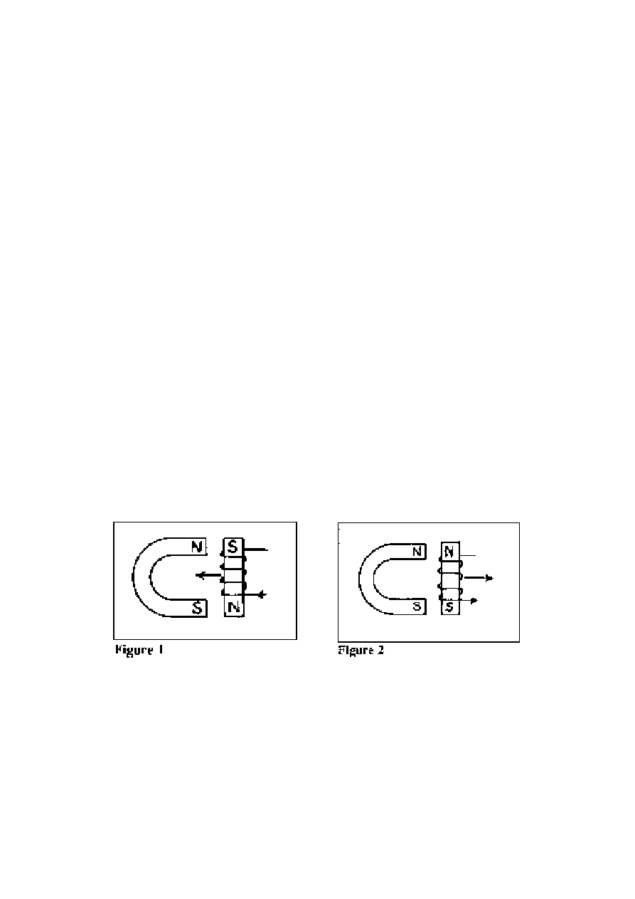
To reduce this to something quite simple, imagine you are sitting at a table in a room
and you have a magnet in one hand and a piece of soft iron in the other hand. See Fig. 1.
The word `soft' in this connection merely means that the iron is of normal composition and
not an alloy or special substance that is used for making permanent magnets. It means that
it readily accepts change of magnetic state and readily loses its magnetic state given a
demagnetizing field. A permanent magnet requires an extremely strong demagnetizing
field before it suffers any permanent loss of magnetism and it recovers from any temporary
reduction of strength promptly upon removal of the less-than-extremely-strong
demagnetizing field. You can feel the pull of the magnet towards the soft iron. The two
having come together, you try to pull them apart to find that it needs a lot of force. If you
4
POWER FROM MAGNETISM: OVER-UNITY MOTOR DESIGN
©
HAROLD ASPDEN, 1996 ENERGY SCIENCE REPORT NO. 9
Figure 3
Figure 4
apply current to magnetize the soft iron bridging yoke then, depending upon the current
direction, the yoke will be pulled towards the magnet with even greater force (Fig. 1) or
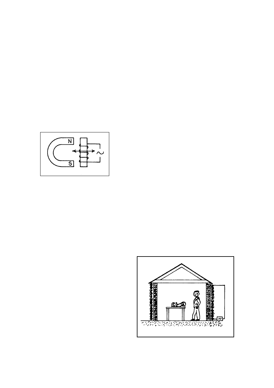
that force will be weakened or even reversed (Fig. 2). If you introduce alternating current
(Fig. 3) then the force will oscillate and you can contemplate building a motor by fitting
a flywheel, connecting rod and crank shaft.
Now there is nothing contrary to simple electrical engineering principles in this
method of designing an electric motor. Indeed, for anyone interested in building model
steam engines there could be a fascination in using the connecting rod, crank and flywheel
arrangement to convert pulsating translational motion into a rotary form of motion. It so
happens, however, that the usual design of an electric motor is more suited to producing
rotary motion. It is based on the magnetic poles on a rotor and a stator moving owing to
a sideways pull which exists even though the interacting rotor and stator pole faces are
equidistant whilst altering their areas of overlap.
However, staying with our horseshoe magnet
and reciprocating engine model, suppose now that,
wrapped around the room, running around the
perimeter walls, there is a magnetizing winding (or
rather a demagnetizing winding) and someone switches
a current on in that winding (Fig. 4). Its field acts on
the magnet and the soft iron just as it would if the
winding were closely wrapped around that soft iron
bridging yoke. You would still find you can easily
separate the two, thanks to that current in the winding,
if it flows in the appropriate direction.
Now you do have a problem. You know enough about magnetism to accept that
magnetic flux lines close around their paths in loops quite close to the magnetic source.
The flux lines emerging from the magnet and the soft iron are therefore all virtually
completely closed well within a metre or so from that table. However, that winding around
the room is all embracing and hardly any flux escapes as a linking flux through that
winding. There is negligible back EMF induced as it accepts the current which breaks the
pull between the magnet and the soft iron. Therefore, one has a situation where power can
be generated from the magnetic reluctance action as the poles come together but we input
no inductive power to weaken that attraction and so allow the poles to separate to reset
them for the next action cycle.
This is a recipe for `over-unity'
operation. We have drawn energy from
the thermodynamic system of the quantum
power state of the magnet and used it to
serve a mechanical purpose and we find
that no energy input is needed to reset the
system for the next cycle of operation.
Now it is not realistic to suggest that
windings should be placed around the
whole room housing a motor but one can
so design a motor that the magnetic flux
circuit is closed within a solenoidal
winding as if that solenoid does house
virtually the whole motor. It is also

5
POWER FROM MAGNETISM: OVER-UNITY MOTOR DESIGN
©
HAROLD ASPDEN, 1996 ENERGY SCIENCE REPORT NO. 9
realistic to contemplate the use of superconductive windings to avoid loss of energy by
normal joule heating produced by current flow. It is even realistic to build a small
prototype machine which does not use superconductive windings and perform tests to
verify the principles just outlined. That is described in Part II below. Furthermore, in Part
III we will come to understand where that energy that is drawn into the machine to give
it `over-unity' performance enters the machine, though a full understanding of its
underlying source, which is within the aether, is beyond our scope here in this Report. For
that one needs to study this author's book `Aether Science Papers' [This was listed as ref.
1996a in the Appended Bibliography that was included in the original version of this
Report. That bibliography is not included here as it can be found on website
www.aspden.org
along with a copy of that book in PDF format.]
To summarize, given that one can design an electrical motor having a magnetizing
winding which has no resistance loss and sets up no significant ferromagnetic inductive
reaction when carrying an alternating current and given that the motor will run at a
synchronous speed set by the pulsation rate of that current, we can design an `over-unity'
motor.
As already indicated the design of a multi-megawatt system will be presented first,
before we come to the design of the small bench-type test machine which the author has
devised. Of necessity, the latter form of machine has had to use magnetizing windings
which are resistive and which do involve inductance, though these are minimized by astute
design. However, since the real significance of this effort is the implication for large scale
exploitation as power generators in the electrical supply industry, it is appropriate to
present the multi-megawatt design next, the object being to arouse interest in government
circles and in the electrical power supply industry.
This is done with deliberation, because there have been several claims by inventors
asserting that they have ‘over-unity' machines. Often the inventors lack the formal
technical academic background of the heavy electrical engineering profession. If their
machines work they get involved with prospective sponsors who want the secrets of the
invention to be kept confidential until they have exploited the rights, but it needs the
engineering talents of the established corporate motor manufacturer to develop the
technology. The reason is one of scale. The larger the machine, the easier the task of
overcoming the power loading involved in breaking through the ‘over-unity' threshold.
A dynamo-electric machine rated at tens of megawatts needs to have dimensions for
which the rotor diameter would be of the order of a metre and a length of two or three
metres. Machines of this size are not built as a speculative experimental exercise. They
should be, in this author's opinion, because the research funding is negligible when
compared with the expenditure which governments waste on high energy particle
accelerators and reactors aimed at hot fusion power generation.
The problem, of course, is that scientists think they know all there is to know about
the way in which the dynamo-electric machine operates. They devote their research efforts
to writing programs for computer-aided design and thereby underline the point that the
basis of their formulations is sound and beyond any dispute.
About ten years ago I asked a university lecturer, who specialised in teaching
electric machine design and was active in creating computer programs for that purpose,
how he allowed for the `eddy-current anomaly' in his calculations. His response to me was
that he had never heard of the `eddy-current anomaly'. I was surprised because I had spent
three years of my life doing Ph.D. research on that very subject in the Department of
Electrical Engineering at Cambridge University in England. I knew that the precise way

6
POWER FROM MAGNETISM: OVER-UNITY MOTOR DESIGN
©
HAROLD ASPDEN, 1996 ENERGY SCIENCE REPORT NO. 9
magnetic flux density B in iron varies with the magnetizing field H is not something one
relies upon from electrical steel manufacturers' specifications. I will not bore the reader
here by enlarging on that theme. If you are interested then do refer to Energy Science
Report No. 3 in this series, but take my word here for the fact that the machine design I
shall describe below would not be something that could perform in the manner predicted
by use of those programs for computer-aided design. Ask yourself, "Could such a program
on offer commercially today really predict the `over-unity' performance of an
electrodynamic machine?"
You see, I know of two fundamental processes that are at work in such machines,
either of which has `over-unity' implications. One is the process that undermined by Ph.D.
research effort. I found that the eddy-current induction losses in electrical sheet steels
could be six times greater than theory predicted, albeit only over a limited portion of the
B-H hysteresis cycle. I attributed this to a loss mechanism as if there was a mystery time
delay in the flux transitions accompanying change of magnetic state. I was not, in those
Ph.D. research years (1950-1953), aware of the possibility of breaching the second law of
thermodynamics. Otherwise I would have been writing about `over-unity' machines and
`free energy' power sources in my early career, rather than now in my retirement. The
mystery which underlies the `eddy-current anomaly' is the regeneration of electrical power
from heat wasted by ohmic resistance loss! That six-fold factor I measured, later to be
surpassed by researchers who found that a factor of 10 was in evidence in some steels
magnetized across the direction in which the steel had been rolled to form in into sheets,
tells me that there is thermodynamic regeneration of power on a mammoth scale. It
exceeds by far any level set by the Carnot criteria and I see in that the basis of a new
technology. That may explain why I deem Energy Science Report No. 3 to be very
important.
Now, in the design of the multi-megawatt machine under discussion here, I need to
keep that `eddy-current anomaly' in mind, while aiming to tap energy from that quantum
world which powers the ferromagnet. The energy source is thermodynamic, but whereas
the `eddy-current anomaly' draws on normal heat energy generated in the steel by
resistance loss, the quantum activity taps entropy of the underlying vacuum medium, or
aether, which is where the quantum (Planck's constant) is determined.
Moving on, I stress that those who will be consulted in the evaluation of what I say
here will not find they can use their computer-aided design techniques to verify in advance
whether or not my machine will work to deliver `over-unity' performance. They need to
understand rather more about `magnetic flux leakage' than they do at present, before they
can even adapt those programs to face this new task. Furthermore, they need first to
understand inductance and the `half-field reaction' phenomenon that I describe in Part III
of this Report. The only way forward is to bite the bullet and spend the money needed to
build the test prototype machine I now describe. They can by all means debate the pros
and cons of my proposal, but they will not be able to deny the validity of my overall
conclusion, because of what I say above by reference to Fig. 4 and what I shall describe
below in Part II.
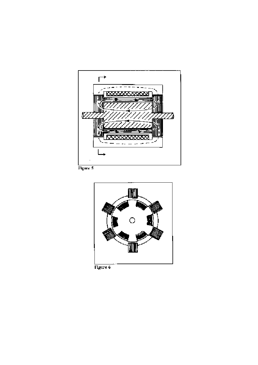
Fig. 5 shows the sectional side elevation of the machine and Fig. 6 shows the
sectional end view from the position indicated by the outer arrow markings. The machine
comprises a solid steel rotor having a laminated set of toothed electrical steel stampings
at each end. The teeth on these stampings form rotor poles which interact with the six
stator pole members. These have the form of laminated electrical steel stampings
7
POWER FROM MAGNETISM: OVER-UNITY MOTOR DESIGN
©
HAROLD ASPDEN, 1996 ENERGY SCIENCE REPORT NO. 9
assembled in a stator support frame (not shown) and forming bridging yokes. The
structure is comparable functionally with the simple arrangement depicted in Fig. 3.
However, there is a fundamental difference in the way in which the magnetizing
winding is incorporated. The main magnetizing winding is solenoidal and shown as the
cross-shaded stator-mounted structure in Fig. 5. It is superconductive. There is, however,
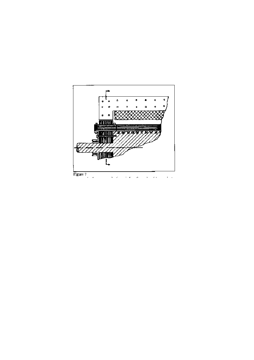
an additional magnetizing winding (not shown in Figs. 5 and 6) that is positioned in slots
around the perimeter of the solid steel rotor. See Fig. 7 for an outline of constructional
8
POWER FROM MAGNETISM: OVER-UNITY MOTOR DESIGN
©
HAROLD ASPDEN, 1996 ENERGY SCIENCE REPORT NO. 9
detail. This winding is a normal copper winding connected between slip rings mounted
on the rotor spigots.
Between adjacent pole teeth on the rotor laminations there are blocks of electrical
steel laminations interfacing with the sides faces of the teeth to guide magnetic flux from
the pole teeth around a closed circuit shown by the three arrow markings on the full line
curves in Fig. 5. The path is through a spiral wrapping of laminated electrical sheet steel
providing infill between the inter-teeth blocks. As can then be seen there is a closed flux
path through the body of the rotor and this spiral wrapping, so that very little magnetizing
current in the rotor winding can produce a flux density near to magnetic saturation around
that rotor circuit. For design purposes one can assume a magnetic permeability of several
thousand so that 15,000 gauss can be developed by a few ampere-turns per cm. length of
the rotor.
Very little power is therefore expended in introducing the priming magnetic
condition of the rotor. So far as induction is concerned, note that the rotor body comprises
solid steel. Once the magnetic flux is set up in it the rapid fluctuations of any externally-
applied field will have no effect on the rotor body. Eddy-current screening will confine
related flux changes to a very small penetration depth and losses arising from that at the
surface of the rotor body will be negligible. However, in resisting inductive flux change
through the body of the rotor, the flux has to remain constant and that means that, external
to the core body of the rotor, it must find a through path regardless of the varying position
of the poles of the machine.
The task in operating the machine is, therefore, that of ensuring that the magnetic
flux from the solid body of the rotor either finds its way back through the spiral laminar
steel wrapping on the rotor or diverts through the outer perimeter faces of the rotor poles
and finds its closure path through the bridging yokes of the stator. The latter route is
indicated by the broken line curves shown in Fig. 5.
With no current in the superconductive winding the paths of least reluctance are
those shown by the full line curves. The 15,000 gauss flux density of the core body will,
9
POWER FROM MAGNETISM: OVER-UNITY MOTOR DESIGN
©
HAROLD ASPDEN, 1996 ENERGY SCIENCE REPORT NO. 9
by appropriate design in determining the ratio of the cross-sectional areas of the solid and
laminar portions of the rotor, be such that 8,000 gauss, say, applies in the right-hand
direction within the laminated portion. However, when current flows in the
superconductive winding in a sense that reverses this flux direction, the design requirement
is that the combined effect should produce a 20,000 gauss flux density in the stator
bridging yoke members.
The plan is to operate the machine by feeding current pulses into the solenoidal
winding to divert the rotor core flux across the pole gaps as the rotor and stator poles come
into register and have no current in that winding as the poles separate. What is so special
about this machine design is the fact that we have built into the machine a basic
polarization bias which allows us to use a solid-bodied rotor construction, needed for
strength in withstanding rotation at, say, 3,600 rpm and have located a single solenoidal
stator winding in a structure that is easy to cool to assure the superconductive condition.
It is special also because we have a ferromagnetic core subjected to pulsating magnetic
flux conditions by a unidirectional current pulse fed to that superconductive winding. Note
further that the flux density range of change in the spiral laminar wrapping around the rotor
is between, say, ±8,000 gauss, which is very moderate in electrical machine design terms,
whereas the flux density range of change in the bridging yoke members of the stator is
between, say 5,000 and 20,000 gauss in the same direction.
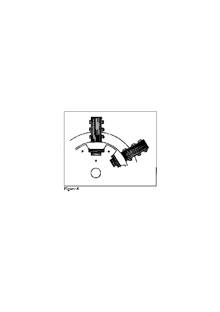
The thickness of the latter members can, as one sees from Fig. 8, be made such that
this 20,000 gauss level of flux density is assured, given that the 15,000 gauss of the solid
rotor core portion will be sustained by induced reaction currents if the current excitation
of the superconductive winding is not perfectly matched to the load conditions. Also, in
the design of this machine an important factor is the retentivity or residual magnetism
trapped in the stator bridging yoke members. This residual magnetism makes it easier for
the basic level of stator flux density to be maintained at 5,000 gauss.
Now, although we have, by reference to Figs. 1 to 4, seen that it is possible to
operate a motor with `over-unity' performance, we have not explained how the energy is

10
POWER FROM MAGNETISM: OVER-UNITY MOTOR DESIGN
©
HAROLD ASPDEN, 1996 ENERGY SCIENCE REPORT NO. 9
drawn in from the aether to balance that gain. As we shall see presently from Part III of
this Report, we need to activate a magnetic core over a range of magnetization where the
ferromagnetic domains in the steel begin to turn owing to the action of a magnetic field,
as distinct from flipping spontaneously by trigger action involving a weak magnetic field.
The latter is what happens at low flux density.
Fortunately, from the viewpoint of our machine design, that `flipping' of flux
direction is avoided in the solid portion of the rotor and is very much reduced in the stator
owing to the magnetization cycle being centred on a flux density of 12,500 gauss.
Hysteresis loss which is associated with those spontaneous flips of the magnetism in the
domains within the steel is very much reduced under these conditions. So far as the
hysteresis loss in the spiral wrapped laminated portion of the rotor is concerned the 8,000
gauss range limit keeps that loss below normal levels prevalent in transformers and
dynamoelectric machines. It follows that the primary loss would be the ohmic resistance
loss in the main winding, but we have avoided that by using the superconductor in its
construction. Note, further, that the strong magnetic flux densities we see in the steel are
not required to penetrate the superconductor material and that the use of a `warm
superconductor' substance is likely to prove commercially viable as the machine design
suggested here is implemented.
It will be apparent to experts in electric motor design who may come to read this
Report that the machine depicted in Figs. 5 to 8 does not exploit the feature by which
inductance of the magnetizing winding is reduced. Yet it does, in a sense and indirectly.
The superconducting winding has to reverse the magnetic flux in the spiral laminar portion
of the rotor. This means that we must supply energy as input to match that stored by
inductance in the pole gaps of the machine. We intend to use that energy priming
condition to develop machine drive torque but, owing to the bias polarization, we intend
to draw in some extra energy into that gap, as will be explained in Part III. This augments
the drive torque. Now, if we were to wait until the machine had used its magnetic drive
fully as its poles reach their in-register condition, before we switch the current off, we
would not get much of that input energy back. However, if the machine is operating under
`over-unity' conditions, we can target a moment to reduce that current so as to get
substantially the whole of that input energy returned from the inductance. In effect,
therefore, though we have to contend with the back EMF attributable to inductance, we
have in sight the design criteria for a machine which possibly might have the merits of the
notional motor arrangement shown in Fig. 4.
It will be easier to understand the technical points involved in this proposition if
some of the design details for operation of the multi-megawatt machine are deferred until
Part IV of this Report. This is because the analysis in Part III will provide a foundation for
understanding the way in which the machine functions to tap aether energy and because
there will be some reference to patents bearing upon the subject and these patents warrant
inspection for their commercial significance. Accordingly, attention is now turned to the
bench-type motor which implements the principle introduced in the above discussion of
Figs. 1 to 4.

11
POWER FROM MAGNETISM: OVER-UNITY MOTOR DESIGN
©
HAROLD ASPDEN, 1996 ENERGY SCIENCE REPORT NO. 9
PART II: The ASPDEN Motor
The ASPDEN motor is based on an evolving design principle which encompasses
several technical features implicit in the name just given. Although ASPDEN is this
author's surname, it can serve as an acronym for:
Asymmetric Shaded-Pole Dynamo-Electric Negentropy machine.
The expression `negentropy' signifies `over-unity' operation, because the usual
expectation in energy science is that entropy, which is a notional quantity representing an
amount of heat Q as degraded by temperature T, or Q/T, always increases. The term
`negative entropy' or `negentropy' implies the reversal of this process and signifies a
regenerative action.
The `asymmetric property' is a subject discussed in Energy Science Report No. 7.
It is introduced by tilting the laminar assemblies constituting the stator poles, the object
being to cause the machine to operate more efficiently when rotating in a specific direction.
The orthogonal relative disposition of the laminar planes as between the stator and rotor
poles accounts for the `shaded-pole' aspect, but this is not strictly a shaded-pole design in
the normal sense. The reason is that the `shaded-pole' feature aims to preclude magnetic
flux from leaving the poles in a direction that retards the drive, whereas the conventional
`shaded-pole' design relies on magnetic flux penetration and that generates unwanted
inductive heating. The current giving that heat shifts the phase of the emergent flux and
creates the drive. The latter is an inefficient process. The former can be quite effective in
supplementing the efficiency of the machine.
From what has been said by reference to Figs. 1 to 4 it will be understood that the
machine must have a single solenoidal winding mounted externally with respect to the
whole operating magnetic circuit, so that it is not restricted in dimensions to the small
aperture space that allows it to fit onto individual pole pieces. Furthermore, we want the
winding to be so positioned on the machine that it acts only indirectly on the pole gap and
lets the magnet system do the work of feeding energy to that pole gap region.
Contrary to the design shown in Fig. 5, we will set the solenoidal magnetizing
winding so that when it is powered to oppose flux in the pole gaps it assists the magnetism
of the magnet. Alternatively, when it is powered to assist the flux in the pole gaps, it
opposes the magnetism of the magnets. This poses no problem, however, because the
magnets are virtually immune from the effects of fields of the strength needed to run the
motor. By putting the magnets into the rotor assembly, it is the soft iron bridging yokes
forming the stator that `see' the power of the field we apply to that magnetizing solenoid.
The magnets set up the basic polarization which develops demagnetizing effects in those
bridging yokes, making it an easy task then for the magnetizing (or rather demagnetizing)
current to reduce the magnetic flux across the poles gaps as they separate. However,
running in the alternative mode with current assisting the pole gap magnetization, the
effective permeability of the irom in the bridging yokes is still of the order of 100, whereas
the effective permeability of the magnets in the rotor is close to unity. It is feasible,
therefore, to run a motor by using a single magnetizing winding wrapped around the whole
body of the machine so as to surround virtual all of its internal flux path.
Inevitably, of course, since we are not talking about the notional embodiment shown
in Fig. 4, we will have some flux leakage that escapes from the winding. Also, there will
be a reduction of magnetic flux through the magnet as the poles separate. This will not
involve significant eddy-current losses if the magnet is of a composition that is non-
12
POWER FROM MAGNETISM: OVER-UNITY MOTOR DESIGN
©
HAROLD ASPDEN, 1996 ENERGY SCIENCE REPORT NO. 9
conductive, such as a ferrite. It would be a problem if one uses an alloy such as Alnico as
a magnet. At least, it is feasible to build and test a small motor that operates by using a
single solenoidal magnetizing winding in the manner just described.
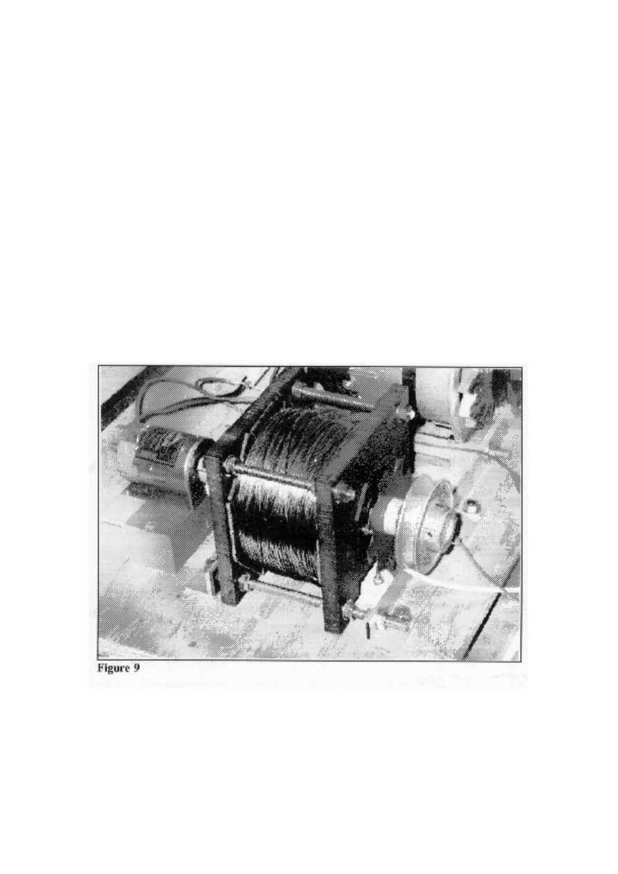
Fig. 9 illustrates the second test machine built by the author. It dates from
April1995.
It uses loudspeaker-type barium ferrite magnets of 60 cm outside diameter, 24 mm internal
diameter and 8mm thickness. The rotor laminations of 90 mm external radius have 8 poles
and an internal diameter of 19 mm permitting a tight fit on a slightly reduced 3/4 inch
diamter brass spindle. There are 8 bridging yokes which comprise small rectangular
transformer laminations of 3 inch by 1/2 inch dimensions.
The machine was fitted with a d.c. drive motor that could serve equally as a
generator and was intended to bring the machine up to speed before current was applied
to the test machine. The decision to use 8 poles proved to be a problem, because it was not
feasible, given the author's circumstances, to assemble a suitable commutator and the
author opted to control the machine electronically.
Note that, to operate with the current assisting the drive as the poles close, one can
expect the machine to be self-synchronizing with the pulsed input. However, in the
opposition mode, unless the pulses have to be correctly timed according to the position of
the motor shaft, otherwise it will lose synchronism.
To the extent that these problems could be overcome, the plan then was to apply
power to the test machine and relieve the load on the drive motor gradually to see whether
the energy input to the test machine was less the energy saving in feeding the drive motor.
13
POWER FROM MAGNETISM: OVER-UNITY MOTOR DESIGN
©
HAROLD ASPDEN, 1996 ENERGY SCIENCE REPORT NO. 9
In short, the question was whether any drive at all could be provided by that single external
magnetizing winding, because it was quite unorthodox to configure a motor so that the
only winding did not link the magnetic circuit traversing the pole gap. Instead, the motor
shown in Fig. 9 was designed with a magnetizing winding that was linked only by stray
leakage flux and there could be no doubt owing to its outer position on the perimeter of the
stator bridging yokes that most of the flux diverted from the pole gaps had still to find its
return passage confined within the magnetizing winding.
Note further that the essential issue of concern was, not the amount of loss caused
in the winding owing to I
2
R heating effects, but whether the energy lost as inductive power
input to drive the machine was less than the mechanical energy gained. Keep in mind that,
whether working in the supporting drive mode or the opposing drive mode, the object is
to draw more mechanical power from the closure of the pole gaps than is supplied as
irretrievable inductive power input, either to augment the gap flux during pole closure or
to weaken the gap flux during pole separation.
One troublesome question faced by the author during these tests of the opposed
mode excitation was that of being sure that the current applied did not exceed that needed
to suppress the pole gap flux, because if it was too large it could simply divert the flux
from the magnet into the ends of the bridging yokes and so through an external leakage
closure path. The leakage had, so far as possible, to be from the sides of the rotor poles
and confined close to the rotor core. That is why the design of the machine was as
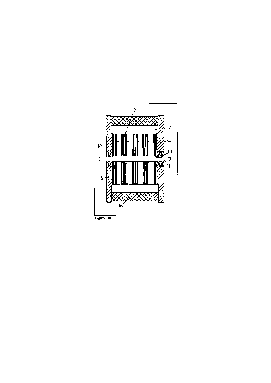
illustrated by the sectional drawing shown in Fig. 10.
14
POWER FROM MAGNETISM: OVER-UNITY MOTOR DESIGN
©
HAROLD ASPDEN, 1996 ENERGY SCIENCE REPORT NO. 9
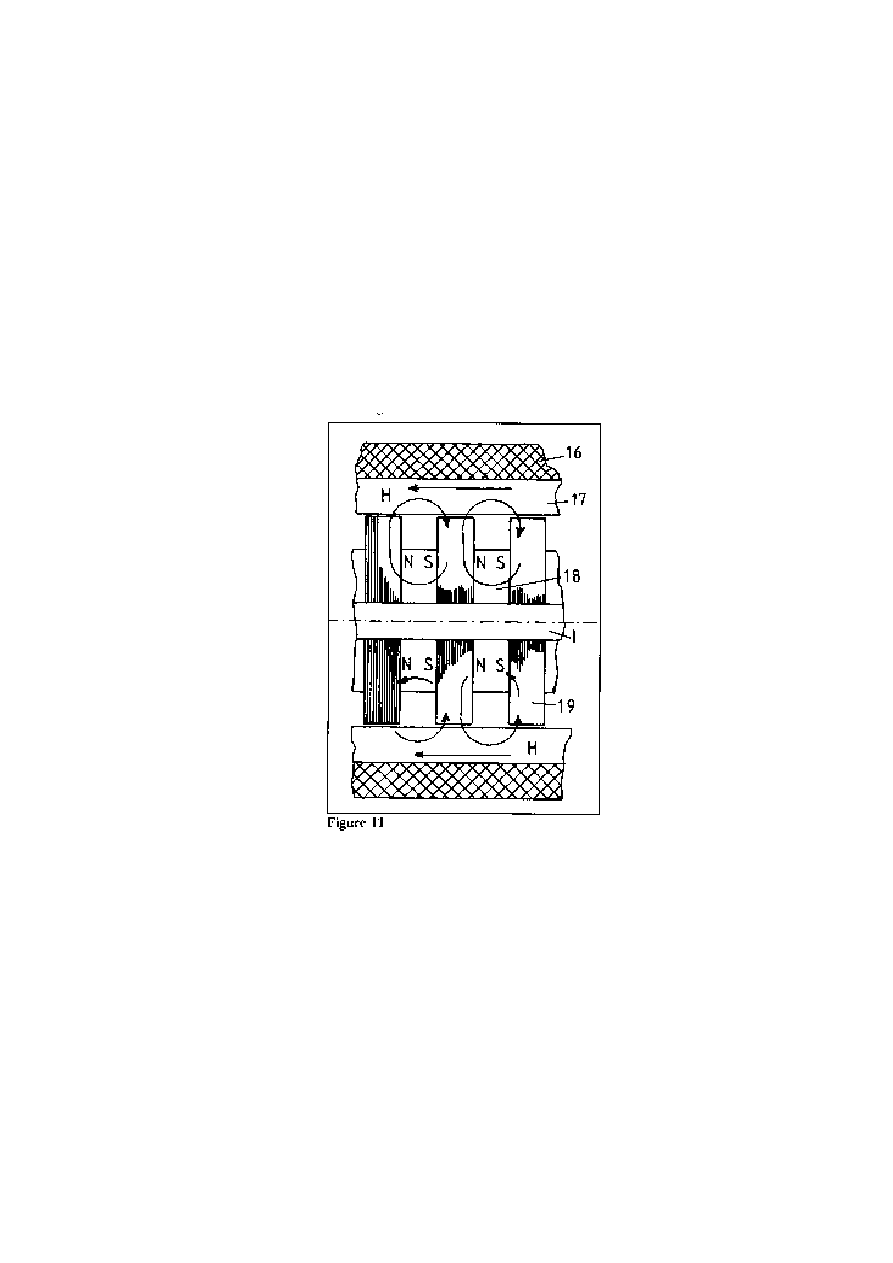
Note that in Fig. 10 and Fig. 11, which shows more detail, there are numerals which
are used because these illustrations are copied from one of the author's pending U.K. Patent
Applications.
The assembly comprises a spindle 1 mounted in bearings 13 in end frame members
14. The latter have shoulders which located stator bridging yokes 17 around which there
is a helically wound coil or solenoid 16. Mounted on the spindle is an interleaved
assermbly of ring magnets 18 and electrical steel rotor laminations 19, the latter having 8
poles uniformly spaced around the perimeter. The angular spacing between the pole teeth
is the same as the pole width. The current pulses fed to the winding 16 are assumed in this
case to produce a field H acting to oppose the tendency of the magnetic flux developed in
the magnets from producing a full measure of magnetic flux through the stator yokes 17.
When no current pulse is present then the magnets can promote magnetic attraction
between the poles on rotor laminations 19 and the stator yokes 17. Otherwise, when current
is present, that attraction is weakened. As a result, by pulsing the winding 16 at the right
timing, the motor will develop a drive torque. Now, although it is not easy to see from
these figures, at times when the current is on and blocking some passage of magnetic flux
through the stator, there is a diversionary route for flux closure from the magnet. The inner
side faces of the rotor pole teeth allow leakage of magnetic flux lines across the axial gap
between adjacent sets of rotor laminations. This is an easier flux leakage route than
passage from the ends of the machine and around a path external to the winding 16. What
happens is that the intensity of the flux through the magnet diminishes somewhat during
the current pulse periods and, of course, at times when the rotor and stator poles are out of
register with one another. The magnets, being of ferrite composition, offer negligible
eddy-current reaction to such flux change. However, in penetrating across the faces of the
rotor laminations the flux from the magnet does encounter such a reaction because currents
are induced in those laminations. This has the effect of tending to keep the flux passing

15
POWER FROM MAGNETISM: OVER-UNITY MOTOR DESIGN
©
HAROLD ASPDEN, 1996 ENERGY SCIENCE REPORT NO. 9
through a magnet and reaching the rotor teeth at a constant level. This enforces the flux
switching between the leakage paths and the stator and means that the flux across the radial
pole gaps varies as the rotor turns in step with the current pulses.
The essential question one confronts is that of knowing how effective the current can
be in driving magnetic flux from the stator. The answer to this is best found by experiment
and the evidence of operation of the machine.
It is found that the pulsing of that helical winding wrapped around the whole stator
assembly will, in fact, impart drive torque to the machine. This means that we can
contemplate making the machine larger in size and making the helical winding so large in
cross-section that its I
2
R loss is very small. Furthermore, if we examine the efficiency of
the machine, measured with that I
2
R loss discounted, we should find that it exceeds unity
or 100%, if our assumptions are correct and much of the flux switching occurs within the
confines of the winding, with little flux escaping from the ends.
The following data is an extract from what was reported in the first report on this
subject submitted to the DTI, the U.K. Department of Industry in July 1995. The full text
of that first report is provided in Energy Science Report No. 7 of this series. As there
acknowledged, the DTI have funded the initial stage of this research project as part of their
SMART Award system for technological innovation.
"The first test on the machine was a test using half-wave rectified 50 Hz a.c. This
meant running the machine at low speed (375 rpm), not enough to test the shaded-pole
feature, which was the dominant interest owing to the funding arrangements. These tests
were, therefore, of a cursory nature just to see if half-wave current pulses did affect the
machine in the manner expected, but more particularly to get a measure of the induced
back-EMF and so the level of flux activity across the pole gaps and to see how the pulse
input relieved load on the drive motor."
“It proved extremely difficult to get the adjustments of the controls just right with
the motor running at 375 rpm for the expected synchronization to establish itself. Then,
and only then, was it possible to reduce slowly, stage by stage, the current input to the d.c.
drive motor whilst holding that 375 rpm speed. in spite of this, several such tests were
performed and the a.c. magnetizing current and voltage were measured as the power input
to the d.c. motor progressively reduced."
"Each such test proved very satisfying, because the saving in d.c. power input to the
drive motor far outweighed the a.c. input as measured in VA (volt-amps), without regard
to power factor. Effort was made to run the system with the test machine driving the d.c.
motor as a generator, but with this test arrangement the system lost the 50Hz synchronism
once the d.c. input current had reduced to about one third of its original value."
"The problem here arose because the d.c. power supply used was a stabilized voltage
supply and it could not drop below 4.5 volts, which is why a load resistor had been put in
series with the motor. Although some time was spent in effort to overcome this, the author
was more anxious to develop a control system for running the machine at much higher
speed and so these 50Hz tests were abandoned."
"One important aspect of the test was, however, the monitoring of the current
waveform as supplied to one test machine winding in relation to the voltage waveform
induced in the unloaded magnetically-coupled and near-identical second winding." (Note
that the winding seen in Fig. 9 is really a two-part winding, each section having 200 turns.)
This gave some versatility for testing and operation, even though both windings are

16
POWER FROM MAGNETISM: OVER-UNITY MOTOR DESIGN
©
HAROLD ASPDEN, 1996 ENERGY SCIENCE REPORT NO. 9
wrapped around the same core system. "Together these waveforms gave an insight into
the inductive power fed in and returned from the machine over the cyclic period of pole
closure and separation."
"It was then very evident that the power factor governing the a.c. power input was
such as to indicate a quite significant excess power, even assuming that the d.c. drive
motor was only 50% efficient. Ostensibly, it seemed that the test machine had to be
operating above 100% efficiency by drawing on thermal heat input."
"The most important observation, however, apart from finding that a pulse amplitude
of about 0.8 amps in the single test winding was needed in the test, was that very nearly
all of the inductive power input to the machine was being returned by the a.c. circuit. The
volt-amp product reversed polarity as the half-wave current decreased. It could do this
because the rectifier diode used could sustain current flow by the winding generating a
forward EMF."
"Now here was a feature that was important. With the machine driven by the
permanent magnet system the inductive power fed in to secure flux switching was not all
used in adding power to the machine drive and even in these 50Hz tests, where current
was reducing as flux collapsed, most was, it seems recoverable. This had been anticipated,
or at least hoped for, in developing the machine design because the relative configuration
of the source magnets and the stator pole pieces, but it was gratifying to see this
confirmation."
"This then became a reason for examining the prospect of building or procuring an
a.c. power source that could operate efficiently at 250-400 Hz to power an inductive load
regeneratively through a diode. The attendant problem was also that of assuring sufficient
frequency stability to be compliant with the synchronous operation of a motor not
receiving its power drive as such from that supply."
"This pursuit tended to run away with the time available for the project, with
partially successful results using the same test machine. Eventually, to move the project
forward, the author decided to use a simple electronic power drive where one machine
winding signalled the control timing needed to put power on the other winding. A pnp
power transistor was connected so as to deliver its collector-base current to one winding
in its ON-state, and inhibited so as to be in the OFF-state when the other winding delivered
a positive polarity signal to the base."
"With such a control system the test results of this Report" (i.e. Report No. 7) "were
obtained, but any inductive power returned from the machine winding is necessarily
dissipated and detracts from the possible efficiency of the machine. This is because the
forward EMF set up by that return of energy causes an unwanted current spike at the end
of the cycle. There was the problem with the system under such test that it could very
easily be set with its magnetic pole gap flux wasting power in oscillations. Had a capacitor
been incorporated without informed design based on test performance then that too could
have aided oscillation, rather than helping to suppress such effects whilst storing energy
for use in the next machine cycle."
The above excerpts from Energy Science Report No. 7 will show the reader that one
cannot just build a motor such as that illustrated in Fig. 9 and expect it to deliver
'over-unity' power on demand. It is essential that one understands how the design features
are supposed to function. What was soon evident was the fact that the magnetic flux
density across the pole gap was far below the level where 'over-unity' operation can really

17
POWER FROM MAGNETISM: OVER-UNITY MOTOR DESIGN
©
HAROLD ASPDEN, 1996 ENERGY SCIENCE REPORT NO. 9
reveal itself in a dominant way. However, the machine was a prototype that could be
scaled up to achieve that result and the tests that could be performed could verify design
feasibility.
The fact that the machine could be operated by the control of that external winding
was the proof this author needed to see purpose in advancing the project.
As can be seen from Fig. 9, a d.c. motor is coupled to the main test machine, the
latter having the all-enveloping helical winding by which it is powered. The 50Hz tests
reported above as well as the electronically pulsed tests reported below were done at an
early stage. It is only recently that the author has reverted to this early machine version
and fitted the vane switch that can be seen behind the pulley. That vane switch comprised
a single 8-pole electrical steel rotor lamination as used in the internal construction of the
rotor. Its teeth swept through a gap in a sensor device including a small magnet and a Hall
effect switch. The latter was used in onward testing to control the commutation. However,
it was not fitted at the time the following test data were obtained.
These data were produced with only half of the test machine winding carrying drive
current, the other half being used to provide the induced EMF controlling the electronic
switching. One can, therefore, see that the I
2
R losses in the winding can be halved by
using both windings for drive power and using either the vane switch, a commutator, or
fitting a winding of a fine gauge wire to produce the induced signal for electronic control.
Further, one can have more turns or use much thicker gauge wire for the main winding.
Essentially, the I
2
R loss can be reduced to a very small value, the more so if the motor is
scaled up in physical size. This is because the loss increases as the square of the linear
dimension of the machine, whereas the drive power increases as the cube.
The objective is to see if the machine derives any drive at all from the current
pulsing of the single helical winding and to get some measure of power gain.
Keeping speeds low, but well in excess of the 375 rpm used in the 50Hz tests, the
whole machine combination was run, first at 800 rpm and then at 1350 rpm, just powered
by the d.c. drive motor. This means that the test machine was simply a load, as the
magnetism fluctuating across the pole gaps would involve some parasitic losses. There
would be hysteresis loss and eddy-current loss and the retentive property of the stator
bridging yokes would apply a stronger drag acting as a brake during pole separation than
was gained as a forward drive during pole closure.
For these speeds the electrical power input was 3.331 watts and 5.255 watts,
respectively. Note that the d.c. motor developed a high torque and was rated at 68 watts
at a speed of 5100 rpm and a 12 volt input at that speed. It was of a kind used to power
model boats. It included permanent magnets and tests indicated that its efficiency was
about 50% over its main working range. It could be run in reverse to generate electrical
power with much the same efficiency. Indeed, two such machines, coupled back-to-back,
were tested to see how much d.c. power input to the drive machine could be recovered
from the generating machine and overall the efficiency was between 25% and 30%.
Keeping the d.c. motor drive power on, the circuit feeding pulses to the winding of
the test machine was then activated and the power supplied to the d.c. motor adjusted so
that the whole machine combination ran at 1350 rpm, as before. The d.c. motor was then
taking a power input of 2.618 watts, less than half the power needed to reach that speed
without the test machine excited. Of course, there was electrical power input directly to
the test machine, but that power was going into the helical winding you see in Fig. 9.

18
POWER FROM MAGNETISM: OVER-UNITY MOTOR DESIGN
©
HAROLD ASPDEN, 1996 ENERGY SCIENCE REPORT NO. 9
Clearly, the machine could be driven by such a winding, even though it was not linked by
magnetic coupling to a flux path through the pole gaps!
Now, these tests were run at low voltage and the transistor circuit was very poorly
designed for the purpose, but the oscilloscope waveforms could be analyzed and it was
possible to segregate the power fed to the test machine to get a measure of the true power
input, ignoring transistor losses. The latter can be reduced to very small proportions by
using MOSFET technology. From this analysis the power supplied to the test machine for
the 1350 rpm speed was 1.718 watts, of which 1.100 watts was VR loss in that helical
winding.
If the latter I
2
R loss is discounted, because it can be reduced to negligible
proportions with appropriate design, and we look solely at the magnetic activity of the
drive, we find that the added 0.618 watts plus the d.c. motor input of 2.618 watts is doing
the work which needed 5.255 watts using the d.c. motor on its own. It took 3.331 watts
to run the system at 800 rpm before the test machine was excited, but, once excited by
magnetic power input of 0.618 watts to the test machine, the 3.331 watts input reduced to
2.618 watts and the whole system increased in speed to 1350 rpm. Ostensibly, to the
extent that we can virtually eliminate much of that VR loss in the helical winding, we have
a reduced power input of 0.095 watts and the machine runs 69% faster.
Now, even if the test machine were 100% efficient and the d.c. motor were 50%
efficient, this could not account for this reduction in power, and so one simply must
conclude that there is evidence of 'over-unity' performance.
Although I could, at this point, begin to describe my onward research efforts and
other machines that I have assembled, I intend to confine this Report to the basic issue of
establishing a scientific basis for the design of an 'over-unity' machine. There are really
only two questions to answer when it comes to assessing the prospect of such technology
impacting our future. These are: (a) can one build a machine of such large power that we
can use it for generating electricity supplied by a utility distribution network and (b) can
one explain the design principles in sufficient detail for scientists to understand the true
source of power?
I see little point in just building a bench-top machine which runs to illuminate a few
light bulbs as if with no input power source, because others who have done that are deemed
to be performing tricks and are not heeded by the scientific establishment. As I see it, it
should suffice to present the outline of a motor design such as is introduced in this Report
No. 9 and as described in Energy Science Report No. 7 and let those interested ponder on
my explanation of the scientific principles that I explain. If they can then see the light
then, and only then, will they see purpose in building their own machines, guided by what
is here disclosed. As with any technological development there is much to learn in the
know how of the design and I do not see myself as a one-man R&D operation competing
with major industrial power engineering interests. Nor is it my role to educate those expert
in that field of endeavour. I will, however, disclose the secrets of that energy world which
I have deciphered from my studies, founded as they are on early academic and industrial
training in heavy electrical engineering and research in ferromagnetism, and I look only
for recognition for my scientific endeavour. This is why I have interrupted my motor
research and given priority during 1996 to producing my book 'Aether Science Papers'
[1996a].
Accordingly, for those having the necessary skill and background experience in
understanding magnetism and electrical theory, especially those versed in power
engineering, I will now move on to Part III of this Report.

19
POWER FROM MAGNETISM: OVER-UNITY MOTOR DESIGN
©
HAROLD ASPDEN, 1996 ENERGY SCIENCE REPORT NO. 9
PART III: The Energy of a Magnetic Circuit
The academic understanding of the way in which energy is deployed within a
magnetic core in which there is a small air gap was a mystery some 50 years ago and has
remained a unsolved mystery, now ignored by professors of electrical engineering.
Professors of physics teach the science of magnetism but are seemingly unaware of the
problem. Indeed, by adopting a particular interpretation of a physical phenomenon of no
practical importance they have, in effect, blocked the way forward to solving that mystery
and in so doing they have not seen the scope for generating power thermodynamically
from the aether itself. The mystery is rooted in the phenomenon discovered by Michael
Faraday, namely electromagnetic induction.
It is an experimental fact that a closed magnetic circuit formed by a ferromagnetic
ring core wrapped within a magnetizing winding will develop a very powerful state of
magnetic polarization around the core even when a quite small current is supplied to the
winding. However, if you so much as slice a gap in the core no greater than two
thousandth of its overall length, then that polarization will immediately lose of the order
of 5% of its strength. Make the gap four thousandths of the core length and you lose 10%.
Professors will tell you that this is caused by `magnetic leakage'. The core section may
have a width of one hundred times that of the gap but those professors will still say that 5%
of the overall magnetism in the ring core is `leaking' from the gap and presumably finding
a route through air that is far longer than that through the air in the gap.
Now, I say that is simply `rubbish' and I can also say that I have yet to see any
textbook present a verified theory of magnetic leakage that explains the phenomenon in
a formal scientific way. The nearest one can get to that, so far as I know, is the Oxford
Clarendon Press textbook published in their Oxford Engineering Series in 1955 under the
title `The Principles of Electromagnetism'. Its author was Professor E. B. Moullin, who
was President of the Institution of Electrical Engineers in U.K. when I began my first year
of research in the Department of Electrical Engineering which he headed at Cambridge
(1950). That is nearly half a century ago. You will find that 5% factor, just mentioned,
on page 174 of that work and you may take note of his final sentence on that page:
"The writer is not able to forecast any relation between the leakage inductance
and the size of the magnet".
However he did find it possible to match up theory and experiment in the case where
the gap was made extremely large by completely removing the bridging yoke in his
experiment. the calculated leakage inductance did agree with the measured inductance in
that case, but there was something amiss in the concept of leakage when the gap width was
small and of the order of a few millimetres.
Professor Moullin presented experimental data of tests he had performed on a core
which was about one metre in overall circuit length and which had a square cross-sectional
area of 8 cm by 8 cm. Although he saw the experimental data as representing `leakage' this
author sees something far more important in that data. There was more energy in the gap
than had been supplied by the magnetizing current!
This was only noticed many years after Moullin's book was published, but it then
caused the author to repeat the experiment and confirm that the flux was not leaking to the
extent suggested. This was reported Energy Science Report No. 1 in this series, where it

20
POWER FROM MAGNETISM: OVER-UNITY MOTOR DESIGN
©
HAROLD ASPDEN, 1996 ENERGY SCIENCE REPORT NO. 9
was suggested that we might be able to build `over-unity' motors, guided by that new
knowledge.
I wish here, however, to enlarge on the academic theme involved in this question of
the core with a small air gap. There are other mystery questions involved in this subject.
Firstly, how can it be that a coil uniformly wound over a one metre length of core can
somehow shed energy confined to a one millimetre length where the air gap is located?
You may say that the magnetic core accepts that energy and transfers it to the air gap but,
again, apart from doing an accounting fiddle and making the energy books balance, how
does energy travel through that magnetic core? We are not dealing with water in a porous
conduit having an empty cavity at one position along its length, though some professors
may be satisfied with that type of analogy.
No, the answer to this question is something rather startling that will surprise any
professor! In fact, what happens when we put electric current through that winding is that
it produces a magnetic field around the whole core and in the onset of that field there is
electromagnetic induction by which energy is fed uniformly into the whole reacting
system, whether the latter is the substance of the core, mere air or even just the vacuum.
I am saying also that all that energy input is lost as heat with no time delay since it is fed
directly into charge in motion over which we have no control. That moving charge can be
in the form of free conduction electrons in a metal or electrons belonging to atomic
structure in, for example, a ferrite or be the charges that sustain Maxwell's displacement
currents in the vacuum field. The energy is lost as surely as if it were shed in a microwave
oven by eddy-current heating. It adds to the entropy of the environment.
The secondary effect of that magnetic field acting all the way around the ring core
is to assert forces on the electric charges that are moving freely as part of that world of
entropy, whether in the air gap or elsewhere around the core inside that winding. No
energy transfer is involved in this steady-state condition because the forces act at right
angles to charge motion. However, by Lenz's law which requires an opposing reaction or
by reference to the derivation of what is known as the Larmor formula, there is deflection
of charge motion into helical paths orientated to set up a reaction field.
The existence of this field even in metals is never mentioned in physics textbooks.
On the contrary, the nearest one gets to this is the occasional reference to what is known
as `the absence of free electron diamagnetism'. Physicists who studied this problem early
in the 20th century were at pains to eliminate it from their thoughts by inventing statistical
reasons, such as spins being paired in opposite directions and so cancelling, their objective
being to avoid the embarrassing question of why a steady magnetic field could penetrate
copper when, in theory, it should be completely suppressed by diamagnetic reaction.
I found those arguments unconvincing and decided that we had to face up to this
question and accept that Nature did react to set up a strong opposing field. I went a little
further in my interpretation of the reaction and added the rider that Nature would limit its
response to the extent that allowed potential energy to transfer into the magnetic energy
of the reacting field. You see, my argument is that forces acting on charge in motion are
not set up by a magnetic field just because some scientist or other enunciated a form of
law. Forces exist only as part of the energy transfer process and are governed by what
happens to energy, the latter being subject to that natural `law of conservation of energy'.
Simple analysis told me that the maximum transfer of energy into the reacting field
occurred when the reaction halved the strength of the applied field. It further told me that
the kinetic energy density deployed from the random motion of that world of entropy and
used in the orientation of the reacting orbital motion of charge will exactly correspond to

21
POWER FROM MAGNETISM: OVER-UNITY MOTOR DESIGN
©
HAROLD ASPDEN, 1996 ENERGY SCIENCE REPORT NO. 9
that we associate with the magnetic field. In other words, I had discovered how magnetic
energy is stored in the vacuum field and how it is recovered when the field subsides. I had
discovered the mechanism underlying the process of electromagnetic induction and I knew
that it involved reversible thermodynamic processes.
Back to our magnetic core problem, I knew that the energy fed into the magnetizing
winding is all shed as heat and lost to the world of entropy but, equally, I knew that, of the
entropy action inside that core, as distributed all along the length of the core and through
that air gap, there is an orientation of magnetic moments producing a uniform reaction
field. Furthermore, this reaction is not just attributable to the field H set up by the winding.
The reaction cannot discriminate between fields set up by windings or those set up by
electrons in motion within atoms in a ferromagnet. So the reaction field really is of strength
B, the full intensity of the flux traversing the air gap. However, its direction is in
opposition to that of the primary magnetization. Now, far from this being a problem, it
was truly wonderful to see what all this implied. The theoretical analysis underlying the
reaction effect had told me that the reaction field would halve the strength of the applied
field. So, if the learned professor tells me that the magnetizing field set up by current in
a winding has a value H but there is no diamagnetic reaction in the vacuum, I say "Oh,
no!" and declare instead that the field set up is 2H but it is always opposed by the reaction
H in the vacuum state and so the measured field is H, but because of that reaction there is
reason to understand how the vacuum stores energy as a function of H and how when the
2H influence is switched that energy is returned to the winding by induction.
The professor may say that this adds up to the same result as his interpretation so
why complicate things; it is better to keep the argument simple. My answer to that is that
it is essential to know the truth where energy is concerned and, furthermore, that it is the
physicist who has complicated things beyond all reason. I refer here to the obvious fact
that if what I say above is correct the intrinsic magnetic moment of a charge in orbit when
measured in relation to angular momentum will be double the value calculated by that
professor on his own reasoning. I then appeal to experiment and ask what happens when
a ferromagnetic rod finds its magnetism reversed. Will it acquire a change of angular
momentum corresponding to its electrons having the gyromagnetic ratio e/mc or e/2mc,
where e/mc is the charge mass ratio of the electron in electromagnetic units?
Lo and behold, the textbooks say that the theoretical value for electron orbital
motion is e/2mc but the value e/mc is observed! So how does that learned professor
explain the anomaly of that gyromagnetic ratio of 2. He invents, or rather Nobel Laureate
Paul Dirac invents, the notion of `electron spin' and says that a spinning electron will set
up twice the ratio of magnetic moment to angular momentum as applies to orbital charge.
The Larmor formula demands the reaction of charge in orbital motion, but Dirac invented
spin. What Dirac did not invent was a way of explaining how magnetic induction energy
can return to electrons in spin. You see, there is no area described by the motion of a
centre of charge and so no scope for flux linkages by which to capture an EMF that can act
on the electron to give it energy!
Dirac was wrong to offer `spin' as an explanation for the gyromagnetic properties
of an iron rod and because of that error professors of electrical engineering live in the dark
when it comes to understanding how energy is transferred to and fro the vacuum by
magnetic induction. They live in the dark by not realising that we can take more energy
from the entropy of our environment than we release, thanks now to this knowledge
presented here.

22
POWER FROM MAGNETISM: OVER-UNITY MOTOR DESIGN
©
HAROLD ASPDEN, 1996 ENERGY SCIENCE REPORT NO. 9
The question I want now to address is the further understanding of how that,
magnetic field set up around the ring core can cause an excess of energy to be fed to the
air gap.
From about 1988 onwards I realised that one could see a way to extract energy from
the aether by magnetic techniques, but I thought it would involve magnetizing a magnetic
core beyond the knee of the B-H magnetization curve. That really means expending
energy in setting up strong currents or contriving to incorporate powerful magnets. The
Moullin experiments on the core with a small air gap did, however, suggest that something
offering energy gain was occurring below the knee of that B-H curve. I now know why.
Essentially it is because we can cause magnetism to turn around corners in a
magnetic core. The magnetic flux wants to follow preferred directions in the crystals
inside the body-centred structure of iron. If it confronts a corner that is not much of a
problem unless there is an air gap ahead around the bend. In that case the magnetism has
to get leverage as it were to contend with the demagnetizing effects of the air gap. It has
to back-up in some way to build an underlying magnetic field action. Once there is a field
H set up inside that iron core then the core is no longer one having high permeability and
it develops characteristics that are non-linear which are accentuated below the normal flux
density level of the knee of the B-H curve.
To glimpse the reason why that `knee' is so important, imagine you are sitting inside
the iron of that core, well away from the air gap. You sense the field H. Now if you are
inside a magnetic domain within an iron crystal you are where the iron is magnetized to
saturation along one of the three main axes of its body-centred cubic structure. That field
H is not going to have much effect unless you are close to a domain wall separating you
and an adjacent magnetic domain. In the latter case the wall could sweep right through you
as the domain polarization reverses. Very little external energy is involved in this exercise.
The field H needed when that air gap is present is far too strong to be wholly absorbed by
the lateral shifting of domain walls. Given, however, that the field H exists, those
magnetic domains that have the most vulnerable orientation, allow some rotational
deflection of their polarization vectors and they will respond as if they have a magnetic
permeability of the order of, say, 50 in gauss/oersted units. With no air gap the normal
B-H curve can show a permeability of several thousand up to the knee and then, as domain
rotation takes over from domain wall movement, the incremental permeability drops to that
lower value. With an air gap the need for H to exist at a significant level, even within the
core in its below-the-knee state, means that some rotation occurs. Note that rotation in the
normal sense begins when all domains have taken up states of polarization along the
preferred crystal axes most nearly aligned with the core axis. The sudden instabilities that
flip the transitions over lower ranges of magnetization account for hysteresis loss, but once
all the triggered transitions are complete and the rotation is smoothly controlled by the
strength of the field H, the hysteresis loss reduces. Indeed, rotation regulated by a field
strong enough to assure saturation involves no hysteresis loss. This can be a considerable
advantage in machines operating with superconducting windings and with limited
magnetic flux ranges confined to the above-the-knee region.
Using that arbitrary value of 50 for permeability attributable to flux rotation
developing at a flux density of, say, 15,000 gauss, the increment HδB which equals BδH
for the normal linear permeability condition can flip to one where a change of B of 1,000
gauss would make HδB 20,000, whereas BδH is 300,000. As will become evident from
what is reported below, this implies a `free energy' power gain of about half of this 15:1
ratio. The reason, as we shall see, is that HδB represents energy supplied by a magnetizing

23
POWER FROM MAGNETISM: OVER-UNITY MOTOR DESIGN
©
HAROLD ASPDEN, 1996 ENERGY SCIENCE REPORT NO. 9
winding whereas BδH represents energy fed into the system by the aether which sustains
the quantum condition of the polarized atoms in the ferromagnetic core.
The formal mathematical summary of this situation now follows. First, we perform
the energy calculations for normal below-the-knee operation, ignoring domain flux
rotation.
Let P denote the intrinsic field intensity set up by the ferromagnetic properties of the
core, so that:
P = B
!H
(1)
Let I denote the current in the magnetizing winding, which has N turns over a total
ring length D. The core has a cross-sectional area of one sq. cm. and an air gap of width
g, so that the length of iron core is D
!g. The winding is tightly wrapped around the core
and we can assume this winding also has a cross-sectional area also of one sq. cm.
At this point I explain that I prefer to use a system of units which takes the vacuum
state as the base of reference, by which it is assigned unit dielectric constant and unit
magnetic permeability, meaning the cgs system. It involves use of 4π but avoids other
complications that tend to dominate and confuse formulations where the fundamentals of
magnetism are concerned.
The energy input W to the magnetizing winding is then found by integrating the
current I in amps times the induced back EMF E in volts. We write:
H = (4π/10)(N/D)I
(2)
and:
δE = (NδB)10
!8
(3)
We will work in ergs, rather than joules, and this introduces a factor 10
7
in the
expression:
δW = (IδE)10
7
(4)
From (2), (3) and (4):
δW = (1/4π)HδBD
(5)
By analogy with the derivation of equation (5) one can see that the corresponding
amount of work performed by the atoms generating the ferromagnetic state of the core is
given by:
δW
i
= (1/4π)PδBD
(6)
From standard physics we know that the energy in the air gap is given by:
W
g
= (1/8π)B
2
g
(7)
It then follows, from (5) and (8) that:
W
g
= W
(8)
if:
B = (D/g)H
(9)
because, given this linear proportionality, the integral form of equation (5) becomes:
W = (1/8π)HBD
(10)
It has been the logical assumption, therefore, to accept that energy conservation
implies the transfer of the energy input W to the air gap and presume that the action
effectively attributes the core-cum-air-gap with an overall magnetic permeability of D/g.
This is in no way a proper physical explanation of the energy transfer phenomenon
because the flux density B traversing that air gap exists essentially owing to the

24
POWER FROM MAGNETISM: OVER-UNITY MOTOR DESIGN
©
HAROLD ASPDEN, 1996 ENERGY SCIENCE REPORT NO. 9
polarization by the ferromagnet and must therefore have been powered primarily by the
energy represented by equation (6). This equation was not used in deriving equation (8).
To proceed, we may add (5) and (6) to obtain, from (1):
δW+δW
i
= (1/4π)BδBD
(11)
which, upon integration, tells us that overall there is a uniform energy density of B
2
/8π, as
we expect. However, this can best be interpreted by saying that the energy supplied to the
gap comes essentially from the
ferromagnet whereas the energy supplied by the magnetizing winding merely tops up the
energy around the whole magnetic circuit to make up for the energy drained into that gap
from the ferromagnet.
This leaves us now with a new perspective. The energy supplied to the
magnetization winding should not be assumed to transfer to the gap. Instead we should
study how the ferromagnet, which delivers energy from the aether by the quantum priming
processes that keep it ferromagnetic, can deliver some excess energy which we can use in
running our motor.
It is intuitive to examine how the H-dependent energy component is supplied. There
are four components of energy of the forms: HδP, HδH, PδH and PδP. The first two are
power input from the magnetizing winding and the other components are power supplied
from the aether. We see that the third term tells us that by applying current to set up the
field H we have tapped some aether energy. Now, so long as P and H are linearly
proportional, the deployment of energy into the air gap will be approximately equal to the
total energy stored by the first component. Also the first and third energy will represent
equal amounts of energy when integrated. Note that the four energy components are
pooled and distributed over the whole core-cum-gap length D, but it just so happens that
H-dependent energy seems to be mainly deployed into the gap. It is then of interest to
consider what happens owing to the non-linearity of the B-H curve. At higher flux levels
PδH will exceed HδP and the difference escalates the nearer one gets to magnetic
saturation.
The consequence of this is that the H-dependent energy being pooled is drawn
progressively more and more from the aether as H is increased. It follows from this that
the reluctance motor power that can be drawn from the air gap will be contributed more
and more by the aether as we take the level of magnetization to higher H levels.
The strict assumption that the energy supplied by the magnetizing coil all goes into
the air gap is clearly incorrect. The energy is lost as heat, but we can recover it from the
aether owing to the inductance effect and the half-field reaction explained above. More
than this, however, we can recover energy well in excess of the amount supplied to the
magnetizing coil because, owing to the curved higher range of the B-H relationship of the
core, the aether sets up a stronger inductance field than applies for a linear B-H
characteristic.
It will now be understood why a high level of magnetizing current and the use of a
superconducting winding can make this technology commercially viable. It will also be
understood why the energy in the air gap exceeds that supplied to the magnetizing
winding, as was shown by the experiments reported in Energy Science Report No. 1.
Remember in that connection that, whereas Professor Moullin had measured the magnetic
flux in the core legs conveying magnetism to the air gap and found that the current needed
to drive a given amount of flux across the gap reduced in relation to the gap thickness, I
have argued that was not due to magnetic leakage. I say it is attributable to the aether
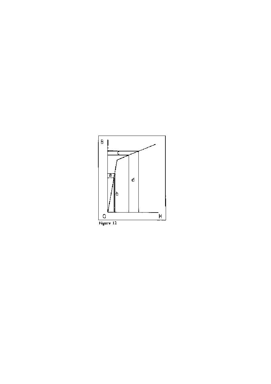
25
POWER FROM MAGNETISM: OVER-UNITY MOTOR DESIGN
©
HAROLD ASPDEN, 1996 ENERGY SCIENCE REPORT NO. 9
feeding, in effect, its own magnetizing current to keep that flux on track through the gap.
I proved this in the experiment I reported by testing the level of flux reaching the bridging
yoke.
In summary, therefore, there can be no doubt that what has been disclosed above
explains how aether energy can be tapped by astute design of a magnetic reluctance motor
and the use of superconducting windings to avoid I
2
R heating.
There is good reason to expect a machine of such design to operate with at least a
5:1 power gain by polarization bias to a basic flux density of 1.5 tesla (15,000 gauss) and
operating over a cyclic flux density range between 1.5 tesla and 2 tesla in the
ferromagnetic core. Note that such flux densities are commonplace in superconductor
magnet technology where there is no ferromagnetic core to assist in developing that level
of magnetic flux.
To underline the point just made it helps to consider what is shown in Fig. 9.
Readers who are familar with the general curved form of the B-H magnetization curve will
realise that the curve has been `idealized' in a straight-line form to facilitate analysis. The
B-H relationship is shown to define four separate areas a, b, c, d which represent,
respectively, HδB and BδH over a range of low flux density and then HδB and BδH over
a range at higher flux density. It can be verified by geometrical analysis that the areas a and
b are equal. This is because the straight line which separates them passes through the
origin at O. However, the area c is between 4 and 5 times smaller than the area d, because
the slope of the straight line separating those areas is much reduced and the line intercepts
the B ordinate at a high B level. The difference is of vital significance in our `over-unity'
motor design. First of all do keep in mind that B and H are not different physical effects
acting at right-angles to one another. They act in the same direction. Secondly, note that
our forebears who coined the B and H expressions really deceived us. They disguised the
formulation by writing it as B equals H plus 4πI, where I was stated as being the `intensity
of magnetization'. Yet all that was meant by this was that H is the effect of the ampere-
turns per cm that we apply to develop the state of magnetization and B
!H or B!4πI is the

26
POWER FROM MAGNETISM: OVER-UNITY MOTOR DESIGN
©
HAROLD ASPDEN, 1996 ENERGY SCIENCE REPORT NO. 9
effect of the ampere-turns that the ferromagnet itself contributes to the state of
magnetization. That source of I in this latter expression is current sustained by the
quantum activity which keeps the ferromagnet alive as a source of magnetism.
Now, if you were an electron sitting in the core of that ferromagnet or some aether
charge form positioned to absorb energy as inductance in the pole gaps associated with that
core, you would not know the difference between the ampere-turns producing H or the
ampere-turns producing B
!H. So, since those areas a, b, c, d are really energy expressions,
as we have seen from the above analysis, you confront the evidence that at low flux
densities, where a equals b, the equal sharing of energy between core and air gap offers
you no power gain helping to drive your motor. However, over the higher flux density
range, where d exceeds c by a very substantial margin, that equal sharing of energy puts
more power into the air gap between the motor poles than you supply to the magnetizing
winding. That is why it is possible to design and run an electric motor which extracts
power from the aether. It is simply a matter of understanding your a, b, c and d alphabet
as applied to what is shown in Fig. 12!
The only problem you have in designing such a motor is one of devising a machine
that does not run away with your input power in setting up the strong currents needed to
reach the near-to-saturation level of magnetism. It is not the input power needed as
inductance energy that is the problem. That is the energy a or c just mentioned. No, it is
simply the ohmic heat loss that arises from the resistance of the magnetizing winding, but
that is a loss we can eliminate as superconductive windings come to be used more and
more in the design of electrodynamic machines. Machines have been devised in the past
using superconductive windings, normally in the rotor of an alternator, but the object is to
produce the d.c. magnetic field and that application has no bearing upon the `over-unity'
machine proposed in this Report. However, the feasibility of using superconductivity in
a multi-megawatt machine is established and the way forward towards power generation
using the `over-unity' performance of the electrodynamic machine described in Part II of
this Report seems now open and welcomes development.

27
POWER FROM MAGNETISM: OVER-UNITY MOTOR DESIGN
©
HAROLD ASPDEN, 1996 ENERGY SCIENCE REPORT NO. 9
PART IV: Commercial Development of the Invention
Readers will now see that I have introduced the expression `invention'. This is
because the technology is the subject of patents involving the author as inventor. The
chances are that the corporate industrial world which has the capacity and the duty to
replenish our power generating equipment will not heed the new technology represented
by these patents. That world does not yet recognize that `over-unity' is a realistic
possibility. So, it seems likely that the patents will serve only the primary purpose for
which they were originally filed, namely to show to future historians that we 20th century
mortals are part of society which, in spite of its vast knowledge, has still much to learn, but
is unwilling to `unlearn' false doctrines to make way for truth.
We belong to a world which was created and which evolves as it is recreated and as
energy is recycled. The machine described in this Report can capture energy as it is being
recycled by the processes which underlie the aether. I have explained how the end-product
of that recycling activity is the creation of electrons and protons throughout space using
energy shed as radiant heat and lost to what we term `entropy'. That was the reason I wrote
`Aether Science Papers' [1996a]. In this Report I have sought to prove that we can
intercept energy as it meanders through that process and capture it through the quantum
coupling that sustains ferromagnetism in steel cores.
The high energy physicist stands aloof from such proposals, even though the physics
involved is clear and conclusive in showing how the precise value of proton mass is
determined in relation to the fundamental constants of the space medium. Accordingly this
Report is offered as a way forward to those in search of a non-polluting new source of
power and the patent rights, so long as they stand in force, may have some commercial
value in support of that prospect. Otherwise, as the rights lapse, their specifications stand
of public record in testimony of missed opportunity in a technological era when we could
ill-afford to turn our backs on such inventions.
That said, I will now revert to the onward design details pertaining to the
multi-megawatt machine, making reference to a patent which relates to what has been
disclosed.
As will be appreciated, the commercial viability of an 'over-unity' power generator
does not just depend upon whether it can operate with a saving on the cost of fuel. It
depends upon the investment, the scale of the machine and its reliability. Therefore, it
seems appropriate to evolve the design by taking the existing technology of the
turbo-alternator power unit as a basis for reference. The future technology proposed here
will involve those same alternators as the electrical power generator. They run at 3600
rpm when developing 60Hz. The prime mover, the turbine, however, is replaced by a
dynamoelectric machine such as that described by reference to Figs. 5 to 8 above. It needs
no nuclear heat source to generate the pressurized vapour powering the turbine. All it
needs is an electrical input to excite its pulsed operation and that can be produced
regeneratively once the system is set rotating at its synchronous speed.
Thus, whereas in a conventional power plant the alternator is brought up to its
synchronous speed by starting the turbine, we do need, in this new technology, to provide
some kind of drive motor or small turbine unit which can initiate operation. Otherwise,
one needs to look to the output alternator or exciter alternator of the system as serving a
motor role during start-up. The exciter alternator generates the pulses for the main
winding on our machine, as we shall see from Fig. 13, but the overall function, given
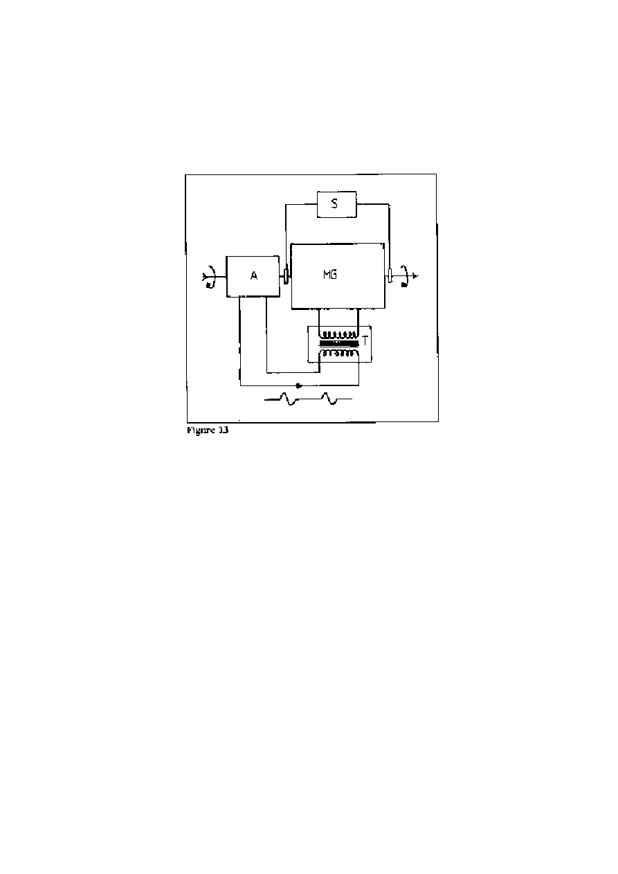
28
POWER FROM MAGNETISM: OVER-UNITY MOTOR DESIGN
©
HAROLD ASPDEN, 1996 ENERGY SCIENCE REPORT NO. 9
‘over-unity’ performance, is that the exciter alternator puts, say, one unit of electrical
power into the winding of the main machine and the latter generates, say, four units of
mechanical power, one of which feeds back to drive the exciter alternator and the other of
which feeds the output alternator or applies mechanical drive as to a ship propeller.
The patent covering what is here proposed does not require use of a superconductive
winding and can avoid that requirement by sacrificing efficiency, but it is assumed that
future technology will use the new warm superconductors.
In this respect, it should not be assumed that superconductivity is used as a
substitute for a ferromagnetic core, that being the normal objective in existing machine
technology. The problems of developing very high magnetic fields in warm
superconductors not yet overcome. Fortunately, in the technology considered here, we
need only moderate fields of a few hundred ampere-turns per cm. to penetrate the
superconductor, because the primary magnetic flux that drives the machine is confined to
a ferromagnetic core. Our objective here is really one of avoiding unwanted loss, both the
VR loss in that main winding and any inductive power loss in exciting the machine. The
objective of the patent is specifically directed to the recovery of induction energy and
overcoming commutation problems.
By having the magnetizing winding on the stator at the outermost position around
the rotor of the machine it is easier to keep it cool enough to assure the superconductive
state. The primary design problem arises from the high induced voltage per turn of the
winding, which could be 1,000 volts in a 100 megawatt installation. For this reason and
to provide thermal isolation for the magnetizing winding, owing to its superconductive
state, a transformer having a ferrite core is needed. This has one primary winding and
several secondary windings, each serving just a few turns of the superconductive winding
on the machine. Referring to Fig. 13, the main generator, denoted MG, is coupled to an
exciter-alternator A, which feeds a commutated sinusoidal a.c. to the primary winding of

29
POWER FROM MAGNETISM: OVER-UNITY MOTOR DESIGN
©
HAROLD ASPDEN, 1996 ENERGY SCIENCE REPORT NO. 9
the transformer T. this has superconductive secondary windings feeding the turns of the
superconductive helical winding on MG. Cooling is via the transformer tank housing T,
where the primary winding is thermally insulated, as the metal of that winding can be
cooled owing to its conductive connection with the exciter-alternator A, where normal
features can be incorporated to cool that machine.
The d.c. power supply S connected to sliprings on MG provides the low power input
needed to polarize the core, though this may prove unnecessary in practice because of the
unidirectional current surges in the winding of MG.
The rather special feature of this design, as covered by the patent, is the way in
which the a.c. input to the transformer is chopped into complete full-wave cycles, say one
in three, in order that the EMF fed to the superconductive winding is pulsed in a timed
phase with the stator-rotor pole positioning in MG. In an ideal case, where there is no
magnetization loss in the machine (current in phase with EMF) as opposed to just inductive
reaction (current in phase-quadrature with EMF), the superconductive winding will allow
the magnetic flux change to conform with the a.c. time-integral of the voltage waveform.
It will be pulsed unidirectionally with a simple harmonic profile and if this is timed
according to the position of the poles so as to assist pole closure, then the machine will
operate in the manner already described. Note that the magnetization loss should be much
smaller than it is in a normal alternator of similar size and so, having regard to the current
strength supplied to pulse the superconductive winding, the phase should not differ too
much from the zero-loss condition.
There is no electronic commutation or switching in the superconductive circuit. The
only commutation is in the exciter-alternator A which supplies the chopped waveform
shown in Fig.13 and interrupts the current flow to the primary of the transformer only at
moments when the current is zero.
It is important to note again that, although there is extensive reference to the
prospective use of superconductivity in the main windings of the generator described, it
is not essential to ‘over-unity' operation. It is, however, an inevitable development, once
warm superconductivity comes to be used in standard design of main power generating
equipment.
The above technique of using the chopped a.c. waveform with a magnetic reluctance
machine biased to polarization close to saturation, all with the objective of running a
machine with 'over-unity' performance is already the subject of the author's U.S. Patent
No. 4,975,608 dated December 4 1990. The design features involving the single helical
winding have evolved since and are the subject of independent patent applications.
The abstract title page and claim pages of that U.S. patent were reproduced in the
Appendix attached to the first version of this Report published in 1996, but since such the
full copy of that patent specification can be see by accessing the U.S. patent office website,
http://www.uspto.gov/
, it is not included here in these pages.
This Report was first published on November 6, 1996 by:
DR. HAROLD ASPDEN
SABBERTON PUBLICATIONS
P.O. BOX 35, SOUTHAMPTON, S016 7RB, ENGLAND
Wyszukiwarka
Podobne podstrony:
Aspden POWER FROM MAGNETISM THE POTTER DEBATE (1994)
Aspden POWER FROM MAGNETISM (2004)
Aspden POWER FROM SPACE INERTIA AND GRAVITATION (1994)
Aspden POWER FROM ICE THE THERMOELECTRIC REGENERATOR (1997)
Aspden POWER FROM WATER COLD FUSION PART 1 (1994)
Aspden POWER FROM SPACE THE CORREA INVENTION (1996)
Aspden POWER FROM ICE THERMOELECTRICS PART 1 (1994)
!Book Folk songs from all over (easy guitar notes)
How to Build Solid State Electrical Over Unity Devices
50 Gb in2 Magnetic Disk Drive System Design Project
David Runciman Political Hypocrisy, The Mask of Power, from Hobbes to Orwell and Beyond (2008)
Pc Power Supply Repair (Nuts & Volts Magazine, September 1996)
[2006] Application of Magnetic Energy Recovery Switch (MERS) to Improve Output Power of Wind Turbine
Power over Ethernet
Ship Power Systems and Design Part 3
44905242 Recipes from Power Foods by the Editors of Whole Living Magazine
Power Does Not Come From the?rrel of a Gun
US Patent 405,858 Electro Magnetic Motor
więcej podobnych podstron