
ENERGY SCIENCE REPORT NO. 2
POWER FROM ICE: THERMOELECTRICS: PART I
by
HAROLD ASPDEN
Sabberton Publications
P.O. Box. 35, Southampton SO16 7RB, England
Fax: Int+44-2380-769-830
ISBN 0 85056 023 3

8
HAROLD ASPDEN, 1994
ENERGY SCIENCE REPORT NO. 2
ENERGY SCIENCE REPORT NO. 2
POWER FROM ICE: THERMOELECTRICS: PART I
8
HAROLD ASPDEN, 1994
Contents
Section Title
page
Introduction
1
Concerning the Patent Rights
2
Development Status: May 1994
3
APPENDIX I: Schedule of Patents
13
APPENDIX II: 'Solid-State Thermoelectric
17
Refrigeration,' IECEC paper: Atlanta,
Georgia: August 1993
APPENDIX III: The Strachan-Aspden Invention:
Operating Principles: October 1989 Report
26
APPENDIX IV: The Strachan-Aspden Invention:
Test Results: October 1989 Report
41
APPENDIX V: The Strachan-Aspden Invention:
Paper on Thermoelectric Power Anomaly:
October 1989 Report
55
APPENDIX VI: Thermoelectric Experimental Device
Construction: Strachan: February 1994 62-71

1
©
HAROLD ASPDEN, 1994
ENERGY SCIENCE REPORT NO. 2
POWER FROM ICE
Introduction
This Energy Science Report summarizes the development status of the Strachan-
Aspden thermoelectric energy conversion technology as of May 1994. Onward research
from that date is the subject of Energy Science Report No. 3.
The basic invention is the brainchild of its coinventors Dr. Harold Aspden of
Southampton, England and John Scott Strachan of Edinburgh, Scotland and it dates from
their first meeting in Canada on the occasion of a New Energy Technology Symposium held
in 1988 under the auspices of the Planetary Association for Clean Energy.
In its conception, the invention merges the technical disciplines of magnetism
(Aspden) and piezoelectricity (Strachan) in a structure which exploits, first and foremost, the
thermoelectric properties of metal. In its onward development and promotion, the respective
professional skills of the two inventors were brought to bear in laboratory assembly
(Strachan) and patenting (Aspden). Geographic separation by 420 miles has precluded a
close working relationship in pursuing this project in a normal technological development
sense, it being a private venture by two individuals, each having other unrelated technical
interests.
In the event, what is an extremely important inventive contribution, that potentially
can provide the non-pulluting refrigeration technology of the future, has remained
undeveloped, notwithstanding some small external R&D funding that has been of assistance
to Strachan.
There are not, of record and suitable for issuance, any detailed experimental tests or
results provided by Strachan. Almost all the documentary material that has been made
available until now has been generated by this author (Aspden), mainly in a patent attorney
or promotional capacity. Much of this latter information is the basis of this Report. One
appended item that is new at this time is the account which Strachan prepared in February
1994 describing the polymer PVDF structure and fabrication of the first and third
demonstration prototypes which he built. The issuance of this Report at this time follows
the recent grant of the relevant U.S. Patent No. 5,288,336 dated February 22, 1994.
The object of this Report, therefore, is to arouse interest in the Strachan-Aspden
invention in those corporations having the necessary R&D resources or ability to fund such

2
©
HAROLD ASPDEN, 1994
ENERGY SCIENCE REPORT NO. 2
R&D in academic establishment laboratories with a view to the disposition of the patents
involved.
Concerning the Patent Rights
[Note added June 2003 when this Report is made available on the
author’s websites
www.energyscience.co.uk
and
www.aspden.org
. The
comments about patent rights which follow no longer apply as the
patents involved were not kept alive, owing to lack of interest by
prospective developers having the necessary disposition to fund the
onward research needed. However, for the record, the text below
remains unamended from its initial form as published in 1994.]
The schedule of patents relating to the Strachan-Aspden technology forms
APPENDIX I. The author, in his Attorney capacity representing the proprietor interest in
these patents, is empowered to negotiate options or outright assignment. Based on the
introductory technical briefing offered by this Energy Science Report, and the information
now being incorporated in further reports, the author also makes himself available for some
limited consultation on onward development by those parties who enter into the necessary
Agreements.
The abstract and title page of the principal U.S. Patent, 5,288,336 is included in
APPENDIX I and those interested in the detailed disclosure and claim cover will no doubt
wish to acquire and inspect a copy of that published patent specification.
Essentially, the details of the operation and technology underlying the invention can
be understood from the descriptive material provided later in this report, but there has been
a shift in emphasis as to this author's technical appreciation underlying physical functioning
of the invention and this features in certain additional patent applications which have been
filed and which, though listed in APPENDIX I, will form the subject of Energy Science
Report No. 3.
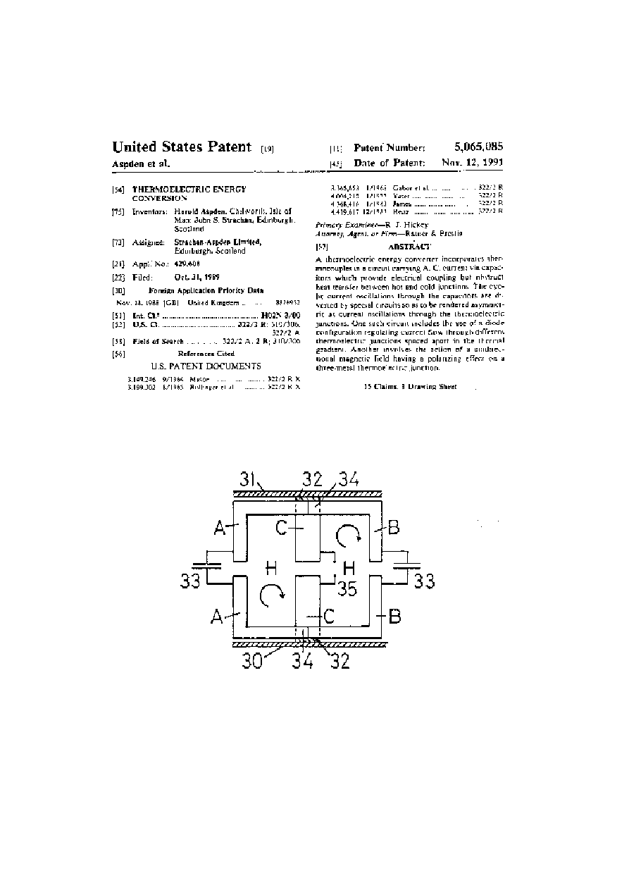
In order, however, to assist the reader who does inspect the primary U.S. Patent No.
5,288,336 and also U.S. Patent No. 5,065,085 and seeks a simple insight into how this author
now views the underlying physics, the diagram in Fig. 1 below may serve.
Fig. 1 Nernst EMFs induced in nickel by heat flow
When a temperature differential exists in a thin film of nickel sandwiched between
dielectric insulation in a parallel plate capacitor, the heat flow carried by electrons is

3
©
HAROLD ASPDEN, 1994
ENERGY SCIENCE REPORT NO. 2
deflected by the strong polarization fields in the oppositely polarized single magnetic
domains that bridge the film thickness. This, by the thermoelectric phenomenon known as
the Nernst Effect develops an electric field polarization as shown by the arrows. It is
orthogonal with respect to the direction of heat flow and the magnetic polarization. It may
then be understood how a lateral oscillation of current flow through the capacitor can choose
a flow path on successive half cycles so as always to transfer charge across the metal plate
electrodes to draw power from an assisting EMF by avoiding the path obstructed by an
opposing EMF. Cooling must then result as that power transfers into the external circuit.
The dielectric insulation obliges the heat flow in the nickel to remain orthogonal with the
current flow direction and also with the magnetic polarization which is necessarily in-plane
in the nickel.
Development Status: May 1994
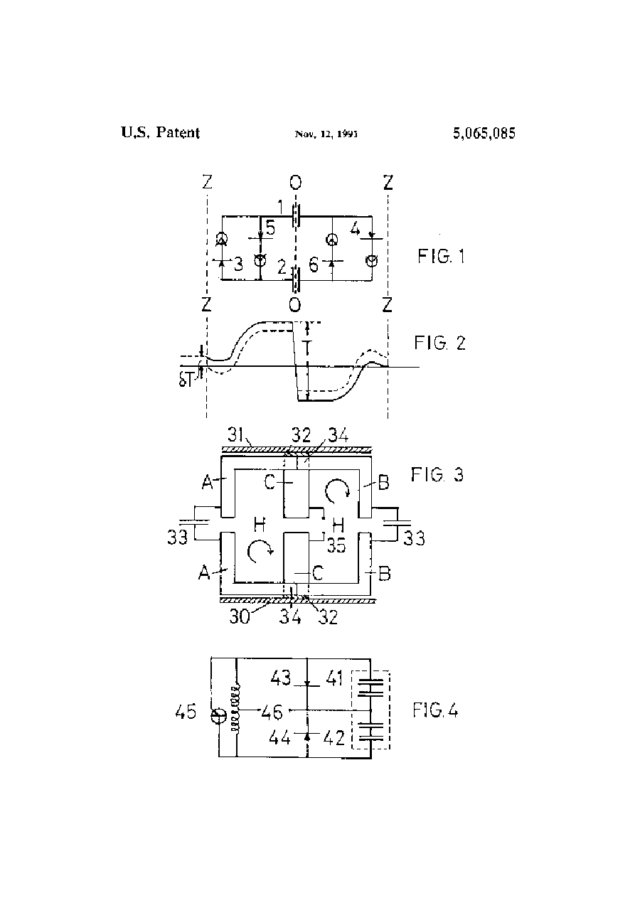
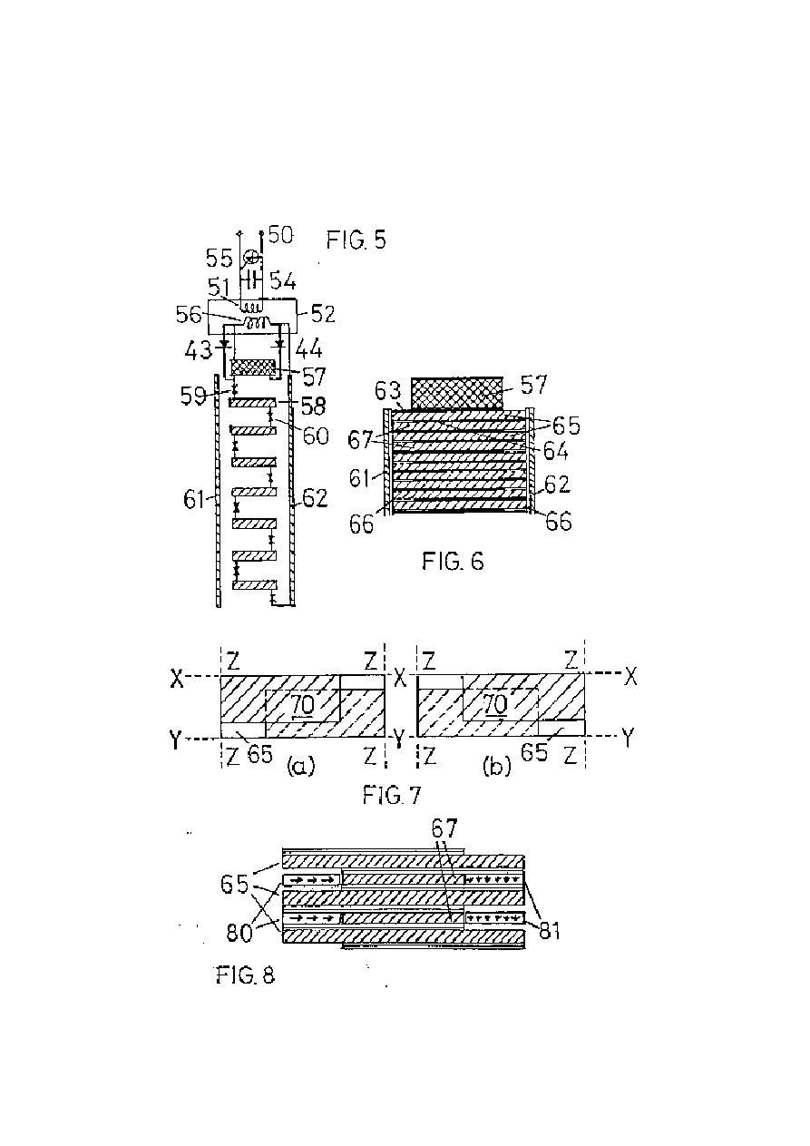
[The figure references in this section apply to the patent specification drawings
included at pages 7 and 8 of this Report]
There were three techniques in the original conception of the invention. The common
feature was the idea of using a capacitative coupling to block heat transfer between the hot
and cold heat sinks whilst contriving thermoelectric energy conversion. Strachan advised
that all three had been tested experimentally and were viable.
The one ready for demonstration (the capacitor stack) was given preference for
onward development. The strategy adopted was to file a first patent application showing
capacitor use in the heat blocking sense (Figs. 1 to 4 of the 18 November 1988 patent filing -
same as those in U.S. Patent No. 5,065,085) and a brief disclosure of the stack (Fig. 4) but
not disclose the detailed assembly of the stack. A second U.K. application filed 5 December
1988 added Figs. 5 to 8 and covered that detail and described the prototype version of the
stack as I understood it at the time.
In the event the capacitor heat blocking proved not to be of particular merit but we
had a basic invention in the disclosure in that the confinement of heat flow to the bimetallic
capacitor plates with transverse current oscillations gave remarkable results.
The subjects of Figs. 1 to 3 were not developed further, even though
they have merit. I persisted in securing patent cover in U.K. and U.S.A., the latter, as just
indicated, being granted as US Patent No. 5,065,085.
The patent cover which followed from the capacitor stack was adjusted and tailored
to the diagnostic findings that emerged from the research on the second prototype and the
international patent filing including US filing did not replicate the features of Fig. 7 or Fig.
8 or include the acoustic oscillation feature that was incorporated in the first prototype.
4
©
HAROLD ASPDEN, 1994
ENERGY SCIENCE REPORT NO. 2
The First Prototype: September 1988
This was a capacitative polymer dielectric stack with bimetallic Al:Ni coatings and
provision for acoustic oscillation of interleaved premagnetized magnetic recording strips (see
Fig. 8).
Strachan has, only in February 1994, and in preparation for a visit from overseas by
interested corporate project engineers, documented the detailed constructional techniques
of that first (and later third) prototype. This forms APPENDIX VI.
Fabrication is very complicated and it is not suggested that the resulting devices did
any more than prove that we have discovered an energy conversion principle that has very
outstanding merit. The task ahead is to develop on the test findings of the much simplified
second prototype.
The Basic Principles and the Second Prototype: October 1989
This was the technology on which the multi-national patent filing was based,
claiming the priorities of the 18th November and 5th December 1988.
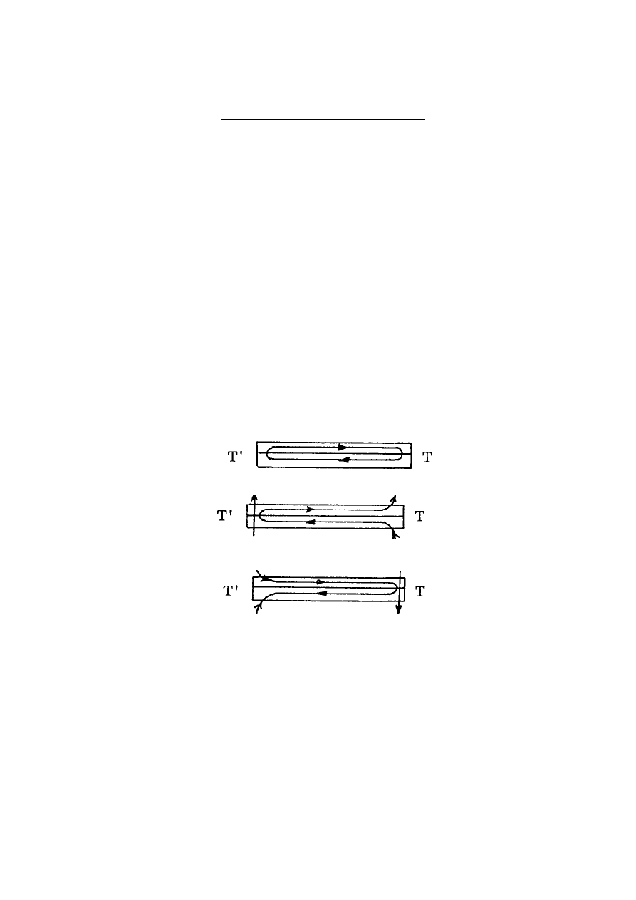
The principle is evident from the following diagram:
(a) Thermoelectric current flow: no transverse excitation
(b) Junction cooling on left with transverse up-current
(c) Junction heating on right with transverse down-current
Note: (1)
We are using a.c. with negligible I
2
R loss.
(2)
The circulating current is that carried by heat flow (Thomson Effect - metals
of opposite electrical polarity).
(3)
The dynamic a.c. current interruption increases the thermoelectric power
enormously (avoids junction cold spot formation).
At that time (October 1989), though the Nernst Effect was in mind and had been
mentioned in connection with the disclosure in U.S. Patent No. 5,065,085 and though nickel,
a ferromagnetic substance, was one of the two metals in the test device, it was not then

5
©
HAROLD ASPDEN, 1994
ENERGY SCIENCE REPORT NO. 2
realised that the Nernst Effect might also play the key role in the functioning of that second
prototype device.
The October 1989 status is evident from the Test Report (APPENDIX IV).
APPENDIX V provides a scientific analysis of the cold spot problem).
The questions outstanding from those tests were:
(1)
What frequency could we reduce to and still get the high thermoelectric
EMF? The cold spot theory implied that we could operate even below 1 kHz,
but the capacitor coupling limited the transverse current and that suggested
building a direct metal conductor coupling following contours of constant
temperature - so as not to divert heat from the junctions.
(2)
What thickness of metal film could we increase to whilst not losing
efficiency? Note that the Thomson Effect circulation fixed the current that
could flow transversely owing to the half-cycle cut-off.
(3)
Which metal combination was optimum?
(4)
What fabrication technique was best to ease manufacture and assure
reliability?
(5)
Why was it that we seemed to be getting more transverse current flow than
the design capacitance of the stack implied from the voltages we measured?
In the event, early in 1990, Strachan was obliged to abandon all work on the project
and the development fell dormant. This was owing to business failure of the sponsors on an
independent manufacturing venture but Strachan was then unable to demonstrate a working
prototype and we were, in effect, then in a worse position than at our late-1988 start point.
The 1991/1992 Scenario
Not having the resources to set up an experimental programme myself, and especially
as I had to sustain the costs of the patents I decided to publish in the hope of attracting
interest from corporations. I had nothing to demonstrate.
My effort to publish in the Journal of Applied Physics caused a referee to say 'publish
but provided more detail is given as to actual construction of the device', but the Editor felt
my amended paper did not go far enough in that respect and so that initiative failed.
By year end 1991 I had an acceptance from a U.K. electronics magazine (the July
1992 article in Electronics and Wireless World) and had a paper scheduled for the 1992
International Energy Conversion Engineering Conference in San Diego.
The publicity in U.K. attracted corporate interest, and Strachan then took the
initiative and assembled the third prototype. The showing of that impressed a major U.K.
company interested in new energy development and they provided new funding for Strachan
for a period of 8 months.

6
©
HAROLD ASPDEN, 1994
ENERGY SCIENCE REPORT NO. 2
I made sure that the demonstration was recorded on video and this has proved helpful
in talks with interested parties. My personal objective concerning onward development has
been to see the test device operate without reliance on the capacitor fabrication, either by an
alternative conductive coupling between the bimetallic laminations or by magnetic inductive
energy transfer, i.e. by intercepting the thermoelectric current by an inductive back EMF.
By year-end 1992, after 4 months of the new funding, Strachan reported on a test
whereby, given a temperature differential in the bimetallic lamination, the magnetic flux
could be controlled at 20 kHz by an electric grid control. However, that research did not
progress to his satisfaction and I have insufficient data for me to make sense of the outcome
of the experiment. The funding for Strachan's research ceased at the end of April 1993.

9
©
HAROLD ASPDEN, 1994
ENERGY SCIENCE REPORT NO. 2
The Aspden Experiment
In September 1993 I decided to initiate my own small experiments, based on the
approach I had been advocating, namely to build a magnetically inductive core system and
feed in eddy-current heating to set up a temperature gradient in bimetallic laminations. The
idea of this, regardless of application to refrigeration or power generation, was simply to
have electrical control throughout the test and determine the relevance of the ferromagnetic
property, metal thickness and excitation frequency.
The outcome of the first experiment has been described in Energy Science Report
No. 1 and further onward experiments will be described in Energy Science Report No. 3.
However, some interesting problems have been encountered in the latter pursuit and
the quest to operate in an all-metal high current mode with no dielectric laminations and
capacitor drive, which is aimed mainly at solid-state electric power generation from input
of heat at higher temperature than is normal where polymer dielectrics are used, may prove
too demanding for this author's private research facilities.
Accordingly, as a guide to readers interested in pursuing the alternative capacitor
construction based on that simple Nernst Effect principle as mentioned on page 2, the
following analysis is included.
Capacitor Stack: Design Considerations
Consider nickel film to have a thickness δ cm and the form of a 1 cm by 1 cm square.
Assume a temperature difference of 1
o
C from one edge to the opposite edge and denote the
specific thermal conductivity of nickel as K watt-cm
2
/
o
C which implies a throughput heat
flow of Kδ.
This heat flow is heat input loss if we do not intercept the heat and deploy it into
electrical output.
The Nernst Effect has a coefficient for nickel which depends upon whether we use
nickel I or nickel II, the latter being larger by a factor of nearly three. On the basis of the
data of record from experiments by Zahn reported in Ann. der Phys. 14, 886 (1904) and 16,
149 (1905) on nickel we can reasonably assume that a 10 V per cm Nernst EMF is set up at
right angles to the heat flow for each degree C temperature drop per cm.
It follows that the heat flow can be intercepted and deployed into output electrical
power if we can provide for a transverse flow of current I amps without there being heat flow
in that same transverse direction, with I given by the equality of 10Iδ and Kδ.
We see that the thickness δ makes no contribution to the heat to electricity conversion
efficiency. This thickness of the nickel merely has to be small enough to assure the single

10
©
HAROLD ASPDEN, 1994
ENERGY SCIENCE REPORT NO. 2
domain condition, say no greater than 50 to 200 microns depending upon the crystal size in
the nickel.
The task is to secure the equality of K and 10I, meaning that with the 1 degree C per
cm gradient and K of the order of unity, I has to be 100 mA per sq. cm of capacitor area to
get optimum operation. A higher temperature gradient requires a proportionally larger
current flow.
The design consideration then centres on the a.c. operating frequency and capacitance
of the structure. If the dielectric thickness is of the order of 10 microns and the dielectric
constant is 10, both of which are demanding design parameters, then a capacitance of the
order of 1 nanofarad applies to the 1 cm. square nickel plate electrodes used and operation
at about 16 kHz will give a current of 0.1 mA per volt. It would need 1,000 V across that
10 micron dielectric to give the 100 mA current requirement.
This is voltage stress requirement is too high and, also, there is another problem
governing the combination of design parameters. This is that, if the thickness of the nickel
is so much greater than the thickness of the dielectric, then the current 'sees' more a flow
through the main surface of a ferromagnetic film and less the transfer of distributed charge
on the surfaces of a dielectric. This can make the current bunch up by a pinch action in that
'negative' resistance flow path through the metal and, to avoid this, the dielectric has to be
thicker than the nickel.
The design therefore proceeds by first deciding the operating limits on the voltage
of a resonant capacitor stack using the inductance of the flow through the nickel in
combination with the capacitance of the stack to determine that frequency. This sets the
thickness of the dielectric. The nickel, if deposited on a substrate dielectric can be quite thin,
say 5 microns, and it is this requirement for thin dielectric larger in thickness than the nickel,
rather than the domain size factor, that obliges use of even thinner nickel films.
Note that the target of a 100% energy conversion efficiency then will depend
primarily upon the scope for increasing the electric breakdown strength of the dielectric
used, assuming simple metal parallel plate capacitance. Alternatively, in order then to bring
to bear a suitable combination of parameters that allow moderate voltage gradients in a
dielectric whilst allowing the current throughput to be adequate at a reasonable frequency,
the way forward is to incorporate in the design the technology of electrolytic capacitors.
This, as this author sees the situation, is what Strachan did in building his prototype
device using a PVDF polymer dielectric and it follows from this preamble discussion that
those best able to develop the subject technology are those corporations who are already
manufacturers of electrolytic capacitors.
Given then that the Strachan device did perform as a cooling device and as a heat
pump able to convert heat into electricity one sees the prospect of developing a thermal

11
©
HAROLD ASPDEN, 1994
ENERGY SCIENCE REPORT NO. 2
electrolytic capacitor that will convert heat to electricity or serve as a Nernst Effect heat
pump with no Carnot limitation on performance.
The reason for this non-Carnot limitation is discussed in Energy Science Report No.
3, but it amounts to the observation that, with heat carried by electrons, the deflection of
those electrons by a magnetic field occurs to bring them to thermal rest (effectively zero
temperature K) as they transfer energy to the capacitor, followed by their recovery of heat
by cooling the substance of their metal host. Carnot efficiency referenced on zero Kelvin
is 100% as far as heat/electricity conversion is concerned.
It then needs little imagination for any enterprising research organization to see that
such technology, if proven in this particular respect, can provide a complete answer to the
world's future energy needs in that, by arranging a conventional Carnot-limited heat pump
in back-to-back operation with the Strachan-Aspden non-Carnot-limited heat pump, and
deploying atmospheric sources of heat one can generate electricity.
Hitherto the non-Carnot-limited conversion of heat into electricity has been elusive
but it is possible in that it already occurs in practice in one half of a thermocouple circuit but
there is there the concomitant requirement that the electricity has to close the circuit through
the other thermocouple junction which makes the reverse conversion.
All that this Report is suggesting here is that the evidence from the transverse-to-
heat-flow current excitation of a heated nickel-electrode capacitor shows how we can
intercept the energy and make the non-Carnot-limited conversion without paying the full
price of the reverse conversion at ambient temperature. The 'lower' temperature conversion
occurs inside the metal as electrons are deprived transiently of their thermal energy. It
occurs at positions in the metal where there is only one prevailing temperature. There is no
way that Carnot criteria can apply unless there are two temperatures associated with that
event and the only temperature that can differ from that prevailing in the metal is the
temperature resulting when the electrons give up their thermal energy by being deflected into
the charged condition at the interface surface of the nickel and the dielectric. That
temperature has to be lower than the ambient temperature of the metal and the electron can
only recover equilibrium and carry heat forward if it then takes heat away from the crystal
body of the nickel.
Given that the ferromagnetic plate electrode is the seat of the action associated with
the Nernst Effect it may seem that there is no need to provide the bimetallic structure of the
Strachan-Aspden embodiments. However, it is important to see that there is a two-fold
benefit from the use of bimetallic laminations. Firstly, the second metal helps to spread the
charge trapped at the interface between the metal and the dielectric and this allows it to
participate more fully in the two-way oscillation of current flow. Secondly, the second metal
brings to bear the Peltier Effect and this can help to sustain temperature gradients which
activate the cooling. Note here that the first and third Strachan-built prototypes had an
intrinsic design symmetry and an input current oscillation developed the cooling action with
no input temperature gradient.

12
©
HAROLD ASPDEN, 1994
ENERGY SCIENCE REPORT NO. 2
In other words, the use of bimetallic plate electrodes meant that the back-to-back
action described above was at work in those devices.
This Report, therefore, highlights the importance of the Strachan-Aspden invention
and hopefully will serve to excite the interest of those corporations having the resources
needed for its onward development.
Energy Science Report No. 3 will be issued when this author has completed some
further experiments and, in the meantime, some of the findings will be available in
confidence to sponsors.
The APPENDIX sequence which follows comprises items written at different times
as this project evolved and there are a few published articles and papers that are not included
owing to the length of this Report.
It is believed, however, that what is described or identified in this Report will serve
as a guide to would-be researchers who wish to become involved in this subject and should
suffice as full information about the invention.
The prospective importance of this technology is so great, having regard to the need
to avoid the pollution problems of existing refrigeration and energy generation technology,
that it is hoped that others will take this project forward on their own initiative. Should any
such researcher make progress in this regard, leading to demonstrable devices confirming
the viability of the technology, then, so long as this author has control of the patent rights
involved there is scope for merging interests in a joint venture.
So far as the availability of rights under the patents is concerned, enquiries from
corporations are invited but no licence deals can be entered at this time as the object is to sell
the patents outright as a total package, which means that licence dealings will be for the
purchaser to determine.
This does not preclude an immediate undertaking in the nature of an option by which
some nominal funding will secure a would-be developer, who already commands the
necessary research facilities, an interest in the rights whilst evaluating the invention based
on prototype building and testing.
Enquiries concerning the patent rights should be directed to me and enquiries
concerning availability of Energy Science Reports should be directed to Sabberton
Publications (see address below).
18th July 1994
DR. HAROLD ASPDEN
c/o SABBERTON PUBLICATIONS, P.O. BOX 35, SOUTHAMPTON, SO16 7RB,
ENGLAND. FAX: Int+44-23-8076-9830. TEL: Int+44-23-8076-9361.

13
©
HAROLD ASPDEN, 1994
ENERGY SCIENCE REPORT NO. 2
APPENDIX I
Schedule of Patents
Patent applications listed as 1-10 below all have the title:
"Thermoelectric Energy Conversion"
and all were filed naming H. Aspden and J. S. Strachan as co-inventors. Dr.
Harold Aspden purchased from Strachan-Aspden Limited all rights in these
applications on 12th January 1992. This company, registered in Scotland,
was dissolved in July 1992, as it had become more expedient to operate from
a company, Thermodynamics Limited, registered in England at Dr. Aspden's
address.
1. U.K. Patent Application No.:8,826,952
Date of Filing: 18th November 1988
Grant as U.K. Patent No:2,225,161
2. U.K. Patent Application No.:8,828,307
Date of Filing:5th December 1988
[This served only as an international priority
document for listed applications 3-4 & 6-10 below.]
3. U.K. Patent Application No.:8,920,580
Date of Filing:12th September 1989
Grant as U.K. Patent No:2,227,881
4. European Patent Appln. No.:89,311,559.2
Date of Filing:8th November 1989
Published Specification No:0369670
Countries designated: Austria, Belgium, Switzerland, Germany, Spain, France
United Kingdom, Italy, Lichtenstein, Luxembourg, Netherlands and Sweden
[Presently pending]
5. U.S. Patent Application No.:07/429608
Date of Filing: 31st October 1989
Grant as U.S. Patent No:5,065,085
Date of Grant:12th November 1991
6. U.S. Patent Application No.:07/439,829
Date of Filing: 20th November 1989
Grant as U.S. Patent No:5,288,336
Date of Grant:22 February 1994

14
©
HAROLD ASPDEN, 1994
ENERGY SCIENCE REPORT NO. 2
7. Japanese Patent Appln. No.:1-299481
Date of Filing: 17th November 1989
[Presently pending]
8. Canadian Patent Appln. No.:2,003,318-5
Date of Filing: 17th November 1989
[Presently pending]
9. Australian Pat. Appln. No.:44771/89
Date of Filing: 17th November 1989
Grant as Australian Pat. No:622,239
10. Eire Patent Appln. No.: 3677/89
Date of Filing: 17th November 1989
[Presently pending]
************
The following patent rights are currently in process. With the exception of
the application identifying Thermodynamics Limited as applicant (sole
inventor J. S. Strachan) all these are registered in the name of Dr. Harold
Aspden as applicant and sole inventor. Dr. Aspden is empowered to
negotiate rights under patents owned by Thermodynamics Limited.
11. U.K. Patent Application No:9,212,818
Date of Filing:17th June 1992
Published Specification No:2,267,995
[Presently pending]
12. U.K. Patent Application No:9,302,354
Date of Filing:6th February 1993
Applicant: Thermodynamics Ltd.
[Presently pending]
13. U.S. Patent Application No:08/018281
Date of Filing:16th February 1993
[Presently pending]
14. U.K. Patent Application No:9,321,036
Date of Filing:12th October 1993
[Presently pending]
The above is the status as at 18th July 1994.


17
©
HAROLD ASPDEN, 1994
ENERGY SCIENCE REPORT NO. 2
APPENDIX II
'Solid-State Thermoelectric Refrigeration'
[This is the text of a paper submitted to IECEC by H. Aspden and J. S.
Strachan, a summary version of which was presented in person by Dr. H.
Aspden at their 28th Intersociety Energy Conversion Engineering Conference
held in Atlanta, Georgia, U.S.A., August 8-13, 1993.]
This paper reports progress on the development of a new solid-state refrigeration
technique using base metal combinations in a thermopile.
Thermoelectric EMFs of 300 µV per degree C are obtained from metal combinations
such as Al:Ni, assembled in a thermopile of novel structure. By providing for thermally
driven Thomson Effect current circulation in loop circuit paths parallel with the temperature
gradient between two heat sinks and also for superimposed transverse current flow driven
through a very low resistance path by Peltier Effect EMF, an extremely efficient
refrigeration process results.
With low temperature differentials, one implementation of the device operates at
better than 70% of Carnot efficiency. It has the form of a small panel unit which operates
in reversible mode, converting ice in a room temperature environment into an electrical
power output and, conversely, with electrical input producing ice on one face of the panel
while ejecting heat on the other face.
An extremely beneficial feature from a design viewpoint is the fact that the transverse
excitation is an A.C. excitation, which suits the high current and low voltage features of the
thermopile assembled as a stack within the panel.
A prototype demonstration device shows the extremely rapid speed at which ice
forms, even when powered by a small electric battery, and, with the battery disconnected and
replaced by an electric motor, how the ice thus formed melts to generate power driving the
motor.
The subject is one of the two innovative concepts which were the subject of the paper
No. 929474 entitled "Electronic Heat Engine" included in volume 4 of the Proceedings of
the 1992 27th IECEC.
The technology to be described is seen as providing the needed answer to the CFC
gas problem confronting refrigerator designers. From a conversion efficiency viewpoint this

18
©
HAROLD ASPDEN, 1994
ENERGY SCIENCE REPORT NO. 2
device, which uses a solid-state panel containing no electronic components and a separate
solid-state control unit which does contain electronic switch and transformer circuitry,
outperforms conventional domestic refrigerators. Since it has no moving parts and contains
no fluid, its fabrication and operational reliability promise to make this the dominant
refrigeration technology of the future.
However, the scientific research and development of the underlying principles have
a compelling interest and pose an immediate challenge inasmuch as recent diagnostic testing
has pointed to a feature inherent in the prototype implementation that has even greater
promise for future energy conversion technology.
This paper will address the subject in two parts. Firstly, the prototype will be
described together with its performance data. Then, the ongoing development arising from
the new discovery will be outlined.
General Operating Principle
The research was based on the use of a commercially available dielectric sheet
substrate which had a surface layer of aluminium bonded to a PVDF polymer film by an
intermediate layer of nickel. This gave basis for the idea of applying a temperature
differential edge-to-edge to promote thermoelectric current circulation by differences in the
Peltier EMFs at the opposite edges of the film.
However, the nature of this material, which was intended for use in a piezoelectric
application and so had a metal surface film on both faces, gave scope for crosswise A.C.
excitation, as if it was a parallel plate capacitator. Of interest to our research was the
question of how the transverse A.C. flow of current through the bimetallic plates would
interact with the thermoelectric current circulation.
Our finding was that the underlying D.C. current circulation which tapped into the
heat source thermoelectrically was affected to an astounding degree once the A.C. excitation
was applied. Whether we used frequencies of 500 kHz or 10 kHz, the thermoelectric Peltier
EMF generated by the Al:Ni thermocouple was of the order of 300 µV/
o
C, which was 20
times the value normally expected from D.C. current activation.
It may be noted that, with the thermoelectric aspect in mind, the PVDF substrate film
used was made to order, being specially coated with layers of nickel and aluminium to
thicknesses of the order of 400 and 200 angstroms, respectively. This was intended to
provide a better conductance matching for D.C. current flow in opposite directions in the two
metals, it being optimum to design the test so that heat flow from the hot to the cold edges
of the film would, by virtue of the Thomson Effect in these respectively electropositive and
electronegative metals, suffice to convey equal currents in the two closed path sections
without necessarily drawing on the tranversely-directed Peltier EMF action.
19
©
HAROLD ASPDEN, 1994
ENERGY SCIENCE REPORT NO. 2
It was hoped that the latter would contribute to the A.C. power circuit by a push-pull
oscillatory current effect whereby heat energy and A.C. electric energy would become
mutually convertible.
A full explanation of the commutating effect obtained by combining matched current
flow of the transverse A.C. and the in-film circulating D.C. is given elsewhere (Aspden and
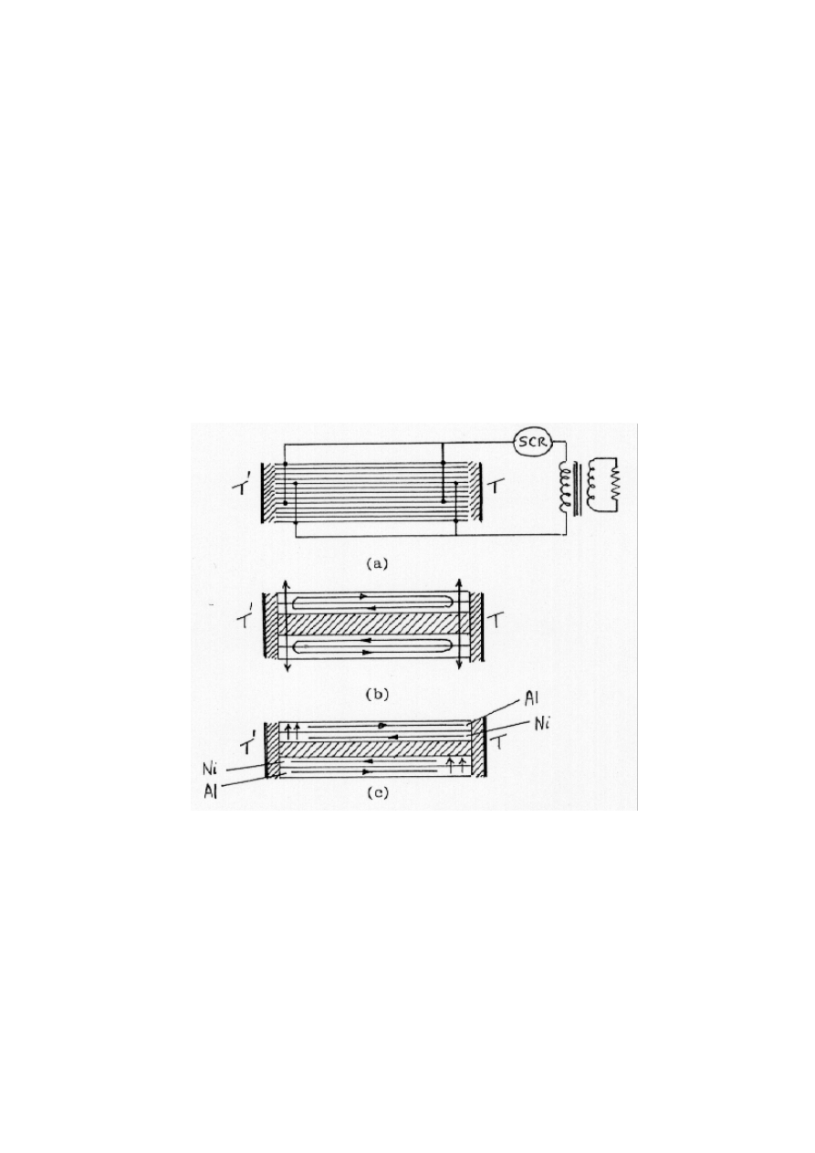
Strachan, 1990 and, Aspden, 1992). However, Fig. 1 may suffice to represent schematically
the functional operation.
Fig. 1(a) shows how bimetallic capacitor plates separated by dielectric substrates are
located between hot (T') and cold (T) panel surfaces with electrical connections at the sides
of the panel. Some of the plates are floating electrically, being coupled capacitatively in
series, whereas the connections linking an external circuit through an SCR oscillator switch
circuit form a parallel-connected capacitor
system.
Fig. 1. Thermoelectric Circuit
Fig. 1(b) shows how D.C. current circulates in two bimetallic plates with a matching
superimposed transverse A.C. current.

20
©
HAROLD ASPDEN, 1994
ENERGY SCIENCE REPORT NO. 2
Fig. 1(c) applies when the A.C. current flow is in the upward direction.
The point is that, in alternate half cycles of the A.C., the current flow operates to
block the D.C. flow at one or other of the thermocouple junctions whilst segrating the Peltier
heating and cooling on their respective sides of the panel.
This has several very interesting consequences.
Firstly, it is found that the Peltier EMF is directed into the A.C. circuit, which being
transverse to the thin metal film, is a low resistance circuit with high but virtually loss-free
capacitative impedance.
Secondly, by diverting the electric power generated thermo-electrically, the D.C.
current flow in the planes of the metal films was virtually exclusively that of heat-driven
charge carriers. The current was sustained by the normal heat conduction loss through the
metal and so did not detract from thermoelectric conversion efficiency by drawing upon the
generated electric power.
Thirdly, and most unexpectedly, it was found that the current interruption precluded
the formation of what we termed 'cold spots' at the Peltier cooled junctions. These latter
spots arise in any normal thermocouple owing to concentrations of cold by Peltier cooling
in a way which escalates so that the junction crossing temperature of a current is very much
lower than that of the external heat sink condition. This stifles the thermoelectric power in
the D.C. thermocouple and it was our discovery that the cyclic interruption of the flow by
the transverse excitation technique accounts for the transition to the very high 300 µV/
o
C
thermoelectric power. The latter has been observed consistently in all three prototypes built
to date and in diagnostic test rigs using the Al:Ni metal combination.
Fourthly, however, the eventual testing of operative devices, though performing
overall within Carnot efficiency limitations, awakened special interest because there had to
be something most unusual about the temperature profile through the device if the best
performance measured was to be bounded by the Carnot condition.
Our research is now casting light upon that latter aspect and may herald a major
breakthrough in energy conversion technology generally. However, even without the latter,
the technology as developed to date does already justify commercial application in
refrigeration systems and that is the primary focus of this paper.
Development History
The project has been slow to progress from its inception. One of us, Edinburgh
scientist, J. S. Strachan (formerly with Pennwalt Corporation) assembled the device as a
small flat module with 500 layers of bimetallic coated PVDF film. It was formed in a 20 by
25 series-parallel connection array which was a design compromise to enhance the capacitor

21
©
HAROLD ASPDEN, 1994
ENERGY SCIENCE REPORT NO. 2
plate area, whilst matching the A.C. excitation voltage and the current rating to the switching
circuitry and dielectric properties of the PVDF.
The device performed remarkably well when first tested, without requiring
transitional stage-by-stage development to overcome problems. This had the effect of
putting in our hands an invention which worked better than we had a right to expect but left
us at the outset not knowing precisely how the different elements of the device were really
contributing to the overall function.
More important, however, though the thermoelectric operational section of the device
was at the heart of the action, the implementation which used the PVDF dielectric and a
capacitative circuit posed problems that were seen as formidable but yet were only peripheral
to the real invention. There was also some doubt as to whether the properties of the PVDF
had a direct role in the energy conversion. There was difficulty in planning in cost terms
the onward scaling-up development, owing to the perceived problems of switching high
currents at the necessary voltage level and frequency.
Commercial pressures and the limited resources involved in what became a privately
sponsored venture to develop the invention, combined with the barrier posed by the switch
versus thermoelectric design conflict, halted R & D and led, sadly, to the project falling into
a limbo state. This was until interest was aroused by the publication in the latter part of 1992
of the above-referenced 27th IECEC paper (Aspden, 1992) and by the article in Electronics
World (Aspden 1992).
Sponsorship interest in the R & D concerning heat-to-electricity power conversion
has now revived, led also by a demonstration made possible by the building of a third
prototype which incorporates 1,000 PVDF substrate thermocouple capacitor plates and
which provides the following test data.
Refrigeration Performance Data
All three prototype devices built to date exhibited a remarkable energy conversion
efficiency. They all operated with different switching techniques and different design
frequencies.
The first prototype was dual in operation in that it was bonded to a supporting room-
temperature heat sink block and the application of ice to its upper face resulted in the
generation of electricity sufficient to spin an electric motor. Conversely, the connection of
a low voltage battery supply to the device resulted in water on the upper surface freezing
very rapidly.
Had this first prototype been assembled the other way up it would have been easy to use
calorimeter techniques and measure heat-electricity conversion in both operational modes.
As it was, an attempt to chemically unbond the device from the heat sink resulted in
corrosion damage which destroyed the device.

22
©
HAROLD ASPDEN, 1994
ENERGY SCIENCE REPORT NO. 2
The second prototype was built, not for self-standing dual mode operation, but
expressly to test the heat to electricity power generation efficiency with variable frequency.
It was not self-oscillating and, as it did not function in refrigeration mode, it offered no test
of refrigeration efficiency. It gave up to 73% of Carnot conversion efficiency in electric
power generation with room temperature differentials of the order of 20
o
C.
The recently constructed third prototype is superior in its electronic switching design and
works well in both electric power generation and refrigeration modes.
There is, however, a circumstance about its operation which means that, for this
particular demonstration prototype, according to its intrinsic magnetic polarization state, it
works more efficiently in one or other of its conversion functions. This particular third
prototype operated with higher Carnot-related efficiency in the electric power generation
mode than in the refrigeration mode. Also, for the same reasons, and an additional factor
concerning the power drawn by the electronics and impedance matching internal load
circuitry, the overall external efficiencies are very much lower than can be expected in a
fully engineered product implementation.
The refrigeration performance data presented below is, therefore, a worst-case
situation and will, without question, be improved upon in the months following the date
when this text is prepared.
The device included an SCR switching circuit which was self-tuning and ran as an
oscillator powered from electricity generated from melting ice in power generation mode or
drawing on a battery supply in the refrigeration mode. However, the power taken up by this
circuitry was factored into the overall performance, meaning that the thermoelectric core of
the device had to be functioning at higher efficiency. Because the electric demands of the
circuit were high in relation to the small demonstration thermoelectric core unit to which it
was coupled.
The active heat sink area of the device was about 20 sq. cm and a typical test
involved a frozen block of 6 ml of water. A test performed after the lower heat sink had
settled to a temperature of 25.6
o
C involved pressing the block of ice in a slightly melting
state onto the upper heat sink with a polystyrene foam pad. The output voltage generated
was fed to a 3 ohm load. It took 9 minutes for the ice to melt, during which time the
measured output was a steady 0.67 V. These data show that a heat throughput of 3.7 watts
generates electric power of 0.15 watts with temperatures for which Carnot efficiency is 8.6%
This indicates performance overall of 47% of the Carnot value.
It is noted that the 73% value obtained with the second prototype applies to a device
which did not incorporate an oscillator demanding power but had simple electronic
switching controlled by, and drawing negligible power from, an external function generator.
To test the refrigeration mode, 3 ml of water was poured into a container on the upper
surface of the device and a battery supply of 7.2 V fed to the SCR resonator with a limiting

23
©
HAROLD ASPDEN, 1994
ENERGY SCIENCE REPORT NO. 2
resistor now switched into circuit to protect the SCR during its turn-off. This resistor
reduced the efficiency further. The circuit drew 6.3 watts and the water froze in 73 seconds.
Since convection was minimal the water closest to the surface froze first and this
immediately formed an insulating barrier which would mean operation thereafter at a
significant subzero temperature at that heat sink during most of those 73 seconds. However,
the overall temperature difference ignoring that temperature drop in the ice was 26
o
C,
associated with a cooling power of 13.7 watts for an electric power input of 6.3 watts. This
represents a coefficient of performance of 2.17 or 21% of Carnot efficiency. Cooling action
at below minus 40
o
C has been demonstrated.
Based on such worst-case data, which neverthless applies to a simple solid-state
device and compares well with the coefficient of performance data of domestic refrigerators,
it can be assumed that the technology is capable of meeting production requirements of non-
CFC refrigerators and domestic air conditioning equipment.
Outlook following Breakthrough Discovery
Diagnostic test work has proved that the device operation is independent from the
piezoelectric or pyroelectric properties of the PVDF substrate used. Given that the action
is truly that of the Peltier Effect, there should be current circulation in the bimetallic thin film
productive of magnetic polarization. By detecting such polarization as a function of the
applied temperature differential one can verify this situation.
It is to be noted that our early research had shown that the thermoelectric EMF could,
under certain circumstances, be greatly affected by the application of a magnetic field to the
thermocouple junctions. Accordingly, the tests aimed at sensing thermoelectrically-
generated magnetic field effects had a particular significance. Furthermore, we had some
interest in the Nernst Effect by which a temperature gradient in a metal in the x direction,
with a magnetic polarizing field applied in the y direction can develop electric field action
in the mutually orthogonal z direction.
It has become, therefore, a subject of research interest to examine how a bimetallic
interface subjected to a transverse magnetic field and a temperature gradient in the interface
direction affects the circulation of thermoelectric current between the metals.
What we have discovered that is of great importance to the development of the solid-
state thermoelectric refrigerator is that the setting up of a temperature gradient in the
bimetallic interface plane between two contiguous metal films will produce a magnetizing
field which readily saturates the metal if ferromagnetic. Thus the nickel film in the
prototypes tested becomes strongly magnetized in one or other direction according to the
direction of the temperature gradient.
When this magnetic field is considered in the context of the Nernst Effect it is seen
that it can lead to a transversely directed EMF governed by the product of the temperature

24
©
HAROLD ASPDEN, 1994
ENERGY SCIENCE REPORT NO. 2
gradient and the strength of the magnetic polarizing field. This tranversely directed EMF
then contributes a bias active in the individual metal and, being in the same transverse
direction, supplements or offsets the Peltier EMF in the prototype implementations.
Remembering then that the heating and cooling actions in the operation of the
prototype devices are governed by current flow in metal which is, adjacent the respective
heat sinks, in line with or opposed to the action of an EMF, one can see how something new
has appeared on the technology scene of thermoelectricity. By using heat to generate current
circulation, which in turn generates a magnetic field to provide ferromagnetic polarization,
a powerful Nernst EMF set up in the metal can act as a catalyst in supplementing the
junction Peltier heat transfer action associated with EMF across a metal interface.
This may well be the action which accounts for the very high thermoelectric
conversion efficiency we have measured.
In order to quantify this as it may apply to the prototypes we have built, note that a
400 angstrom thickness of well-magnetized nickel subjected to a temperature drop of 20
o
C
across a metal length of 2.5 mm, implies a Nernst EMF of the order of 6 mV across the 0.04
micron nickel thickness.
Though small, this is significant alongside the Peltier EMF across a junction, but the
really important point is that this Nernst EMF is set up in the metal and not across a metal
junction interface. In that metal, owing to the free-electron diamagnetic reaction currents
within the nickel and around its boundary, which offset in some measure the atomic spin-
polarization of the ferromagnet, there is then scope for some very unusual thermodynamic
feedback effects. Those diamagnetic reaction currents which are themselves powered by the
thermal energy of the electrons have a strength related to the magnetic polarization and so
exceed, by far, the thermoelectric current flowing across junction interfaces. The heating
and cooling processes transfer power between the heat sinks in proportion to current times
voltage and the in-metal action within the nickel could therefore generate very significant
thermal feedback, thereby greatly enhancing the efficiency well beyond that of the normal
thermoelectric bimetallic junctions.
This action only results where one of the metals is ferromagnetic and the
configuration of the device is such that an applied temperature gradient promotes internal
circulation of thermoelectric current around a closed circuit able to develop a magnetic field
in the nickel directed transversely with respect to the temperature gradient.
Conclusions
The exciting prospect for future development of refrigeration techniques centres on
the possibility that the feedback process can be greatly enhanced by using thicker metal
films. It is hoped, therefore, that the research reported here will soon advance to probe the
limits of efficiency that are possible with this new solid-state refrigeration technology.

25
©
HAROLD ASPDEN, 1994
ENERGY SCIENCE REPORT NO. 2
In this connection the truly exciting prospect arises from the possibility that the
efficiency barrier set by the Carnot criterion can be penetrated.
To understand this, note that the Peltier EMF on the hot side of a thermocouple is
proportional to the higher temperature T' and that at the cooler side is proportional to the
lower temperature T. For a given current circulation the heat energy extracted is
proportional to T and the net input of electrical power is proportional to T'-T.
This is the reason why the coefficient of performance has a Carnot limit of T/(T'-T).
Now, if there is a thermal feedback action that is regulated by a Nernst EMF and we
can contrive to assure that the forward transfer of heat arises from a uniform temperature
gradient in the ferromagnetic metal, then the Nernst EMF is the same on both sides and the
amount of heating on the hot side is, in theory, exactly equal to the amount of cooling on the
other side.
There is conservation of energy with negligible net energy input but heat transfer
from the cold to hot heat sinks and this implies a very high coefficient of performance not
temperature-limited according to the Carnot requirement.
This, therefore, is the challenging possibility that looms in sight and is heralded by
the rather fortuitous discovery of the surprisingly high performance characteristics of the
Strachan-Aspden base metal thermoelectric power converter.
The Strachan-Aspden device uses what the inventors see as conventional physics,
albeit with the innovation of combining transverse A.C. excitation with D.C. thermocouple
excitation. However, it does seem that in some curious way the device happens to have
features which bring some new physics to bear. By producing a thermally-driven current
crossing a strong magnetic field in metal the Lorentz forces on that current develop a
transverse reaction EMF in that metal. The combination of that transverse Nernst EMF with
a circulating current confined within the metal can, it seems, operate to transfer heat
thermodynamically, working through the underlying ferromagnetic induction coupling in the
metal. This is somewhat analogous to the way heat energy is somehow diverted into
electricity in being routed between the hot and cold heat sinks in a conventional Peltier
thermocouple circuit. It does, however, introduce new physics to the technology of
refrigeration and offers great promise.
References
Aspden, H.; Strachan, J. S., European Patent Application No. 0369670, 1990.
Aspden, H., SAE Technical Paper Series No. 929474 1992.
Aspden, H., Electronics World, July 1992, pp. 540-542.

26
©
HAROLD ASPDEN, 1994
ENERGY SCIENCE REPORT NO. 2
APPENDIX III
The Strachan-Aspden Invention: Operating Principles
[October 1989 Report]
The object of this Report is to merge a review of the status of the project at
the time the primary research was abandoned in 1990 with an evaluation of
the design options for taking the project forward. Appendix III, together with
IV and V, comprise extracts taken from an earlier Report dated 23rd October
1989 and prepared when the project was most active. These provide
background information.
**********
INTRODUCTION
Imagine a panel fitted like a sheet of glass into a window frame but serving as a silent
solid-state heat engine which uses electricity to cool the room in summer and heat the room
in winter with the high efficiency of a heat pump. Imagine the same panel fitted into a
glazed enclosure designed to trap atmospheric radiation to develop a temperature difference
across the inner and outer surfaces of the panel and using the trapped heat to produce
electricity.
The Strachan-Aspden invention provides the technology needed to fabricate such a
panel and brings with it a quite interesting challenge. This challenge is a design problem.
The task is that of deciding between a mode of construction that has been tested in prototype
form or one that needs some research in advance of development but should prove superior
from a commercial viewpoint. The task is to scale down an internal operating voltage and
increase internal current flow coupled with conversion to a pulsed d.c. mode of operation
rather than having a resonant circuit sustaining a.c. oscillations through the dielectric of a
capacitor.
The R & D activity had just begun to address this problem when the Scottish small-
business entrepreneurs who undertook initial development deserted the project as their other
business ventures failed. This has meant that an invention which could make a major
contribution in the effort to free the world from polluting energy technology became virtually
dormant.
The merit of the invention can be judged from one simple technical fact. Operating
from a room temperature source of heat and melting ice the tested prototype device was able

27
©
HAROLD ASPDEN, 1994
ENERGY SCIENCE REPORT NO. 2
to generate electricity at close to the Carnot efficiency limit by a technology utilizing the
thermoelectric power of base metals at a rating equivalent to 20 kw electrical power
output per kg of metal in circuit. In a non-developed hand-fabricated form, the device
performed at 73% of Carnot efficiency. This is not optimum performance and is far from
exploiting the full design potential.
The invention opens up a wholly new field of technological opportunity. It arises
from a major scientific breakthrough which involves a totally unexpected discovery. In
original conception the invention aimed to use the properties of a dielectric film as a barrier
to heat loss by thermal conduction and the bimetallic coating on the film as a thermocouple
circuit to convert heat into electricity. In reality it was discovered that the transverse
oscillatory current excitation of a thermoelectric circuit produced an astounding effect on the
thermoelectric power of the base metal combination.
1989 RESEARCH PROGRESS REPORT
[This section is copied from the 23rd October 1989 report]
"The plan during 1989 was for Strachan to engage in detailed research and onward
development of the technology involved with a view to consolidating the patent position by
year end.
The research phase has not been without its traumas, essentially for two reasons.
Firstly, there was a set-back in that to perform certain tests on the prototype device aimed
at measuring efficiency at an elevated temperature it had to be detached from its heat base.
Secondly, in attempting this using a chemical solvent to separate two parts, the chemical
found its way into the main structure which, lacking in foresight on this possibility, had not
been sealed against such contamination. This upset its operation; it was a lesson learned, but
at that stage a set-back to the development plan. It was not then possible, without rebuilding,
to really get the full measure of the performance properties needed to comply with the initial
programme. The question at issue was one of controlling temperature differential on a
sustained basis with measured heat throughput rather than monitoring a small piece of ice
as it melted by sucking heat from the environment, some of which was being intercepted to
produce electricity in transit through the device.
Even before this set-back many experiments on components were performed to test
operative features in isolation, with the early recognition that something totally unexpected
was involved. A very substantial increase in thermoelectric EMF per junction, far in excess
of reference data indication, had been achieved thanks to the particular operating technique
adopted in the prototype. However, in spite of these progressive steps, the onward
development necessitated a firm measure of the minimal operating efficiency of the basic

28
©
HAROLD ASPDEN, 1994
ENERGY SCIENCE REPORT NO. 2
device and, though the eventual products will be far easier to assemble, a small panel was
made which closely conformed in design with the original but included certain modifications
excluding what by then had come to be regarded as possibly non-essential features. This was
a gamble, especially as the construction was very intricate and time-consuming when done
by hand, with ongoing circuit tests during assembly to assure proper current distribution and
unifomity of response. However, in the event, the device, once completed, did perform with
equal or better results than the original version.
Happily, in confirming the new design assumptions made during the first months of
1989, the tests on this second device proved to be a major step forward and justified the
filing of a third patent application in September 1989.
The second set-back proved how wise it was to have held back on early publication.
The onward research investigations showed that what had been a primary design feature
intended to block heat loss and so improve efficiency was not directly effective in that role,
at least in the way we intended. Indeed, a fortuitous discovery had been made by proceeding
on that assumption and the phenomenon involved had had the same effect, but not for the
reason first believed. Instead of physically obstructing heat flow through the device, as had
been intended, the operative technique actually converted almost all the heat into electricity
before it reached the point of no return and so allowed very little to cross by thermal
conduction and so escape as waste.
It was only after this discovery was made and an understanding reached concerning
the process involved that it became possible to begin to consider disclosing to the scientific
community, not just what had been achieved, but why it works so well.
This disclosure is being made now that the initial applications for foreign patent
rights have been registered and the purpose is expressly to attract interest from those who
have the resources to help in the development of this new energy technology. It is only by
such shared action on an equitable commercial basis that the benefits of the Strachan-Aspden
invention can make their full contribution in helping to reduce the world's energy pollution,
whilst conserving the chemical qualities of fossil fuel resources for future generations."
The above text, quoted from the 23rd October 1989 report was prepared as a
confidential document. The sponsors used the report to try to attract investment in
their overall business interests and shortly thereafter ceased to fund R & D on this
invention. Apart from initial costs of overseas patent applications, the funding that had
been provided had been mainly that needed as salary by Scott Strachan whilst involving
him as a consultant on other projects. As yet, therefore, this important energy
invention has not had the benefit of serious development funding.

29
©
HAROLD ASPDEN, 1994
ENERGY SCIENCE REPORT NO. 2
The research effort up to October 1989 had concentrated on simplifying the assembly
of a prototype test device using the bimetallic coated film which could also serve as a
capacitor dielectric. The immediate objective was to measure the heat-to-electricity energy
conversion efficiency and explore the design criteria involved. The inventors were, however,
mindful that the principles of operation of the device did not really depend upon capacitative
operation and the current limitation which that implied. It was deemed possible to extend
the technology to structures which involved an all-metal through-circuit for electrical power
and some plans were made for building such all-metal structures for bench testing. Had the
research been active in 1990 this alternative would have been thoroughly tested so that a
choice could have been made as to the best mode of implementation in a production
assembly.
It is noted that no formal product design proposal, with costing that could be used in
a business plan, was drawn up in the 1989 period. Strachan was engaged on the preliminary
functional testing to assess the performance and determine the optimum techniques and
choice of materials. Without this information, one could not price either the market value
of a product or its manufacturing cost. Even now, product costing is not really possible until
the through-metal-circuit R & D investigations have been completed. The fact that a 20 kw
rate of electrical power generation can be delivered by 1 kg of metal, drawing on a
temperature differential of 20
o
C, is the best indicator that it must be possible to build an
operational unit that can be costed low enough to justify a very large sales volume. The real
question now concerns the best configuration of the metal used and the best choice of metals.
THE STRACHAN-ASPDEN INVENTION
[The
section in quotes is copied from the 23rd October 1989 report]
The following is a technical description of the principles underlying the Strachan-
Aspden invention written on the assumption that it would form the basis of a lecture by
Harold Aspden to an audience who would later witness a demonstration of the operational
device by Scott Strachan.
"Before outlining the technical nature of our invention there is one very significant
point that I think is worth registering at the outset. The test device on which our company
was founded used the thermoelectric properties of contact between two base metals,
aluminium and nickel, to produce electrical power from a low grade heat source. A
temperature difference of 20 degrees relative to room temperature was sufficient to produce
a steady power output of one fifth of a watt per cubic millimeter of metal in the thermocouple
circuit. Scaled up, that is 20 kw per kg of metal. It did this with an efficiency that was well

30
©
HAROLD ASPDEN, 1994
ENERGY SCIENCE REPORT NO. 2
above 50% of Carnot efficiency for this temperature range. This is as good as internal
combustion engine performance where the fuel burns at more than 2,000 degrees.
This is an invention which should have been made 50 years ago as part of the solution
of the electronic age. As to the patentable merits of the invention, it has been said that even
a simple invention can be judged highly if 'a long felt want' is satisfied. No one can deny that
we need a breakthrough in the pollution-free energy field and what I have to disclose is not
quite so simple.
The device is essentially a flat panel that can be fitted like a window or used as a heat
exchange interface in an engineered installation to convert heat energy into electricity or to
use electricity to cool one face of the panel and heat the other face.
It is simply a panel with an electric supply lead. All that there is between the two
faces of the panel is a laminar structure of metal with some insulation, together with a small
electrical transformer and an electronic control unit connected to the supply lead via a switch.
What is special, however, and what causes this device to be a revolutionary
breakthrough in energy technology, is governed by a combination of two special features.
These we have called:
(1) DYNAMIC EXCITATION FEATURE
(2) TRANSVERSE COMMUTATION FEATURE
There is also a third feature which has been used in the prototypes to enhance
efficiency even further, but which will only be used in very special products. This is termed:
(3) THIN FILM ENHANCEMENT
Basically, we are talking about a thermoelectric system using either the Seebeck
Effect or its converse, the Peltier Effect. By connecting different metals in an electrical
circuit and positioning the respective junctions on the hot or cold side of the panel, the
passage of D.C. current is related to the thermodynamic effects. Energy can be converted
in this way, as is well known, but not, until now, with an efficiency that has such
overwhelming implications in the field of energy technology.
The thermocouple working in Seebeck mode operates to extract heat from one
junction and inject heat at the other junction. The balance of energy is electrical in the sense
that an EMF or voltage is set up at the cooled junction and this can deliver output power in
the electrical circuit, provided it is smaller than the back EMF or reverse voltage at the
heated junction.

31
©
HAROLD ASPDEN, 1994
ENERGY SCIENCE REPORT NO. 2
In efficiency terms, the operation is governed by the fact that the heat absorbed or
produced at a junction is proportional to the junction temperature measured on the absolute
scale, that is referenced on -273 degrees centigrade. Therefore, if one junction is at -3
degrees centigrade (270 K) and the other at 27 degrees centigrade (300 K), we can produce
300 units of electricity from the cooling effect at the hot junction but have to give back 270
units of electricity by heating the cold junction. The net gain is electricity, in theory, could
be 30 units of electricity for the price of a 270 unit thoughput or 300 unit input of heat energy
for these low temperature conditions. These high numbers of heat energy units should not
be regarded as energy waste. They relate to what is called 'enthalpy', which is a measure of
heat content referenced on 273 degrees centigrade below zero and even ice has an enormous
heat content on this basis of reference.
What has just been described is the so-called Carnot efficiency. It is 10% for the 30
degree temperature differential considered. It works either way, in the sense that if electricity
is supplied rather than produced, the input of 30 units of electricity can cause a transfer of
270 units of heat from the outside temperature source at -3 degrees and heat a room to 27
degrees. This is the Peltier mode of operation and it provides a tenfold gain on the use of
the electricity in an electric heater, assuming full Carnot efficiency. Operating at 50% of
Carnot efficiency, a 10 degree heating can be achieved with only 7% of the power needed
by an electric convector or radiator.
The reason we do not see such Peltier heat pumps used on a large scale for domestic
heating or power generation purposes is, very simply, that it has not been possible to achieve
an adequate level of performance relative to the Carnot limit.
Technically, the obstacle has been the need to find materials which can be used to
form thermoelectric junctions having a high Peltier coefficient. This is the factor relating the
power conversion at a junction with the amount of current passing through. It is measured
in millivolts at room temperature. The dilemma facing this technology is that if base metals
such as copper, iron, aluminium etc are used to form junctions, the EMFs involved are very
small. However, the electrical conductivity is good and this helps to reduce losses.
Unfortunately, in such metals good electrical conductivity goes hand in hand with good
thermal conductivity and then we lose heat by leakage through the metal circuit between the
hot and cold junctions. For base metals this has been seen as a 'no win' situation, because
efficiencies of the order of 1% of Carnot efficiency are representative of practical
performance.
For these reasons, the attentions of the last half-century have concentrated on special
metals, alloys, and semi-metals or semi-conductors. The price paid for accepting poor
electrical conductivity of perhaps one thousandth that of copper has been rewarded by a
much reduced thermal conductivity and a very much increased thermoelectric power. The
EMF involved is typically in excess of 200 microvolts per degree with a Peltier coefficient

32
©
HAROLD ASPDEN, 1994
ENERGY SCIENCE REPORT NO. 2
of 60 millivolts at room temperature. Such devices are useful for special applications, where
small current throughput and low efficiency are of no consequence, but their general use as
Peltier heat pumps or electric power generators has been limited.
A typical state-of-the-art power generator using junction materials formed from alloys
of bismuth, tellurium, selenium and antimony has a design specification that recognizes a
maximum operating efficiency of 22% of Carnot when opeating with a high temperature
differential of 300 degrees using a source at 600 K. The electric power produced, assuming
perfect accord with the design specification, is of the order of 0.1 kw per kg of metal used
to form the thermoelectric junctions.
Practical applications depend upon the energy throughput rate as well as efficiency
and what is being offered by the Strachan-Aspden technique is so far ahead of state-of-art
technology on both these counts that one must wonder how the technology could have gone
so far adrift in missing the real potential of the Seebeck effect.
Some words from the book 'Direct Energy Conversion' by Professor Stanley Angrist
bear upon this:
"At the time of Seebeck's work, the only devices available for producing electric
current were extremely weak electrostatic generators. Fifty years passed before
steam engines drove electromagnetic generators. It was, undoubtedly,
electromagnetism that caused succeeding generations of physicists and engineers to
lose interest in the curious effects of thermo-electricity. The only widespread use
of the effect was in the measurement of temperatures by means of thermocouples.
It is difficult to say how the history of electrical engineering and electronics would
have developed had Seebeck's discovery been widely employed."
Those researching this field today seem to have been attracted by the empirical
discovery of new materials and have gone astray in not researching the basic question why
metal junctions have such low thermoelectric power. This is very curious, bearing in mind
that classical thermodynamics theory tells us that the theoretical power of base metal
combinations is of the same order as that of these special materials.
I must admit, however, that though, with hindsight, we can bring this problem into
focus, we did discover the solution only when we were performing diagnostic tests on our
principal prototype. In short, we had built something that worked too well and we were
wondering why.
The point rests on the question of whether the metal used increases in electrical
conductivity or decreases in conductivity as temperature increases over the operating range.
In base metals conductivity decreases with increase in temperature. This means that at the

33
©
HAROLD ASPDEN, 1994
ENERGY SCIENCE REPORT NO. 2
cooled junction the decrease in temperature improves conductivity. Now, if the electric
current flowing through the junction is uniformly distributed this will simply mean that the
junction has a uniform cooling across its interface. However, if, as occurs in electrical
discharges in gases, the flow tends to be in short-lived filamentary surges, there is the real
possibility that a current could develop a non-unifom pattern of cooling. A current flow
concentrated at one position would form a 'cold spot' in the junction interface. The electrical
conductivity there would increase and so the current would favour that path of least
resistance and become locked on the cold spot. This could drive the temperature so low that
the effective temperature governing Carnot efficiency is not what we see from the external
actions.
In other words, owing to the increase in electrical conductivity with drop in
temperature, the thermoelectric power falls far below the theoretical potential of the metal
junction. There is therefore an enormous loss of efficiency when base metals are used in
thermocouples in what has been conventional technology.
Why does this not affect the special materials as well? The answer is tha such
materials do not have the same temperature characteristics. The p-type alloy bismuth-
telluride (25%) with antimony-telluride (75%), and n-type alloy bismuth-telluride (75%) with
bismuth selenide (25%) have, for example, electrical conductivities which reduce the
temperature if operated above 300
o
C. Such a temperature characteristic means that cold
spots cannot form. Therefore, if we want to use base metals, with high energy throughput,
the only way we can hope to get high efficiency is by somehow preventing the cold spots
from forming in these materials. This is exactly what we achieve by the DYNAMIC
EXCITATION FEATURE. Its effect is to increase the thermoelectric power of an
aluminium-nickel couple from 17 microvolts per degree to a value well in excess of 300
microvolts per degree. Since this factor operates as a squared effect, because it drives
proportionally more current and puts proportionally more voltage behind it, the electric
power becomes hundreds of times greater than expected on conventional design criteria.
This, therefore, is a major advance because it allows us to use basic metals with high
capacity for delivering current, rather than expensive compositions with very limited energy
throughput capacity.
What is the DYNAMIC EXCITATION FEATURE? In simple terms, this is a
technique by which, instead of causing a steady D.C. current flow through the junctions, we
interrupt the flow several thousand times per second in such a way that the current flow
through the cooled junction relocates rapidly and before the non-uniform temperature or cold
spot condition can develop.
The advantage is that we get the kind of thermoelectric power (i.e. voltage) from
aluminium-nickel junctions that is available from bismuth-telluride, but, for comparable
dimensions, the higher electrical conductivity of the base metal device allows more than one

34
©
HAROLD ASPDEN, 1994
ENERGY SCIENCE REPORT NO. 2
hundred times as much active power (wattage) to pass through. This takes us well forward
technologically, but the TRANSVERSE COMMUTATION FEATURE which will now be
described advances performance even further, so far in fact that we can trim back our design
objectives on efficiency to simplify the manufacture and so reduce the cost of this
technology.
The conventional design of a thermoelectric device involves having two distinct
junctions between the two metals, one junction being at a higher temperature than the other.
The metal between the junctions merely serves as a conduit for electric current and,
unfortunately, provides a channel for heat loss by thermal conduction from the hot to the cold
junction. Rather than trying to develop special materials which facilitate flow of electric
current but obstruct heat flow, we followed another route. We also had in mind that a really
good commercial device could hardly take in heat and produce electricity if the materials
were not good conductors of heat. After all, the heat has to get into the device before it can
be deployed into electrical form.
Our device uses two metal layers which interface over the whole distance from the
hot side to the cold side. We then set up a thermoelectric current which it drives around the
closed circuit formed by the interfacing metal layers. We accept the full measure of heat
conduction through the metal by allowing it to travel through the full length of the metal
layers. However, note that the route taken by the heat is never further away from a junction
interface than the thickness of a metal layer. This means that the heat has repeated
opportunity to be effective in generating electric power as it progresses along the junction
interface. This is a feature vital to success. Unlike the conventional themopile where, once
clear of the hot junction, the heat travels to the cold junction to be dissipated, we ensure that
it has repeated 'bites of the cherry', as it were, en route to that destination, with the effect that
very little even reaches the point midway where the current flow reverses. By 'reversal' is
meant flow from metal B to metal A, whereas initially it was flowing from metal A to metal
B.
This feature has a remarkable effect on efficiency because virtually all the heat
supplied is converted into electricity. The $64,000 question, however, is how we intercept
the electrical energy flow around the closed loop circuit formed by the two contacting metal
layers and so gain access to that electricity before it is all dumped back into heat over the
interface area where the thermoelectric current flow reverses.
This is where the 'transverse' excitation aspect of our invention holds the key to a
successful energy converter. As can be seen from Fig. 1, we stack bimetallic layer upon
bimetallic layer to build a stack between a hot surface and a cold surface and the external
current flow involves a transverse current flow through the whole stack.
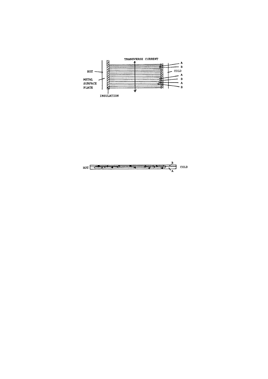
35
©
HAROLD ASPDEN, 1994
ENERGY SCIENCE REPORT NO. 2
Fig. 1
The point then to keep in mind is that at the interface between the two metals forming
each layer there is a thermodynamic effect causing a voltage to act from metal A towards
metal B and this voltage varies across the layer according to the local temperature. It is
greater, the higher the temperature. Because of this there is an imbalance of voltage from
point to point in the heat flow direction across the contact interface in each layer when a
temperature differential exists between the side faces of the stack. This imbalance causes
current circulation in the sense shown in Fig. 2, where one layer is presented in enlarged
form.
Fig. 2
All this does is to cool one side and heat the other, with the result that the metal
conducts heat from the hot side to the cold side.
However, now suppose that we provide a channel for transverse current flow up or
down the stack. This means current flows transverse to heat flow but, in this layered
arrangement, it augments or opposes the thermoelectric current as it traverses a junction,
depending upon the direction of flow of the transverse current. The channel for this
transverse current is assured if there is good interface contact between all metal layers in a
stack formed by metals A, B, A, B, A, B etc in sequence. Owing to the symmetry of the
system a current travelling right in metal B will have to overcome the same potential barrier
or back EMF at the cold junction whether it goes up or down the stack. However, we cannot
have some contributing to tranverse current flow by going up the stack in one part and
elsewhere having some going down the stack. Either the current all goes up or all goes down
or there is no transverse current flow at all and the thermoelectric current flow is everywhere
confined to its own bimetallic layer.
The current will take the path of least resistance, or will it? If there is an external
resistive load connected in the transverse current flow path, then the easier route for current
will be the closed circuital track shown in Fig. 2. Some small amount of current should flow
either up or down the stack, because the external circuit offers a supplementary route for
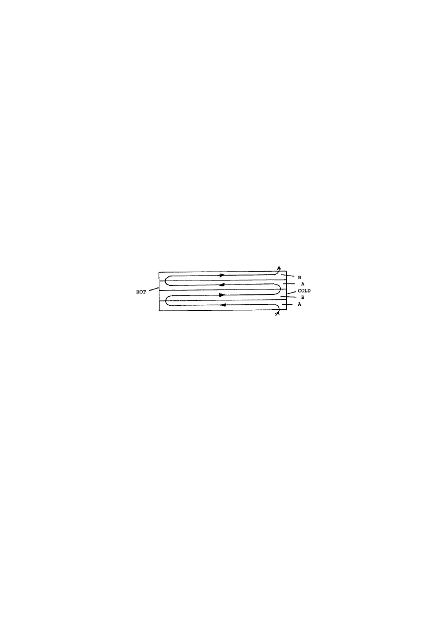
36
©
HAROLD ASPDEN, 1994
ENERGY SCIENCE REPORT NO. 2
current. However, this will not give us scope for causing cyclic interruption of the primary
junction current, nor will it give access to any real power output. Indeed, without the
dynamic excitation, the voltage driving the circuital current in Fig. 2 is very low.
Nevertheless, the circuit is a bistable system and how it behaves when relying solely on the
thermoelectric voltage produced by the heat input is not the same as its response when a
voltage surge up or down the stack governs the action.
Given a trigger effect which causes a transverse current surge up or down the stack,
the junction current can be interrupted by a fast cycling switch in the external circuit and,
once this happens, the full high powered thermoelectric action comes into effect, but this is
a condition only effective if the transverse current is strong enough to exceed the normal
steady state junction current. Given some intrinsic inductance or capacitance to sustain
transverse voltages which carry the action through the zero current transient states, the device
can become locked into the dynamic excitation mode to deliver an electrical current powered
by the full thermoelectric action. In this mode the current flow is represented by the snaking
flow shown in Fig. 3.
Fig. 3
The device actually works and exhibits extremely high efficiency in converting heat
energy into electrical power output. Indeed, the capacitative versions of the device which
have been constructed use bimetallic layers less than 0.1 micron in thickness (one micron is
a millionth of a meter) and 300 such layers of one square cm area interleaved with 28 micron
thick dielectric could generate 300 milliwatts of electrical power using just over one calorie
per second of heat input at 40 degrees Centigrade and output at 20 degrees.
This is quite remarkable, bearing in mind that even these temperatures and their
differentials are so low. It is even more remarkable when one realises that the power
generated is at a rate in excess of 20 kilowatts per kilogram of metal used to form the
thermoelectric circuits. This capacitative device does, however, make use of the enhanced
electrical conductivity of thin films, which accounts for the very high efficiency obtained.
To bring the design parameters into perspective it is useful to consider a formula for
the figure of merit Z normally applied to thermoelectric systems. This is presented in Fig.
4.

37
©
HAROLD ASPDEN, 1994
ENERGY SCIENCE REPORT NO. 2
Z ' βα
2
σγ/K
FIGURE OF MERIT Z TRANSVERSE COMMUTATION FACTOR β
THERMOELECTRIC POWER (VOLTS/DEGREE) α SPECIFIC ELECTRICAL CONDUCTIVITY (MHO-CM) σ
THIN FILM ENHANCEMENT FACTOR γ THERMAL CONDUCTIVITY (WATT-CM) K
Fig. 4
This formula, when multiplied by the operating temperature, in absolute degrees
Kelvin (say, 300 at room temperature) is a measure of the potential electric power generated
as a ratio of the heat conducted from the hot junction to the cold junction and so wasted.
This assumes operation with a low temperature differential and allowance has to be made for
the duality of the metal paths, which are in parallel for heat flow and in series for electrical
current flow. This tends to reduce the ratio by a factor of 4. Also, the potential electric
power output depends upon the load resistance as related to the intenal resistance of the
device.
All in all, therefore, to build a viable thermoelectric power converter the Seebeck
coefficient α has to be as high as possible. The Strachan-Aspden devices tested so far are
offering α values in excess of 300 microvolts per degree centigrade using base metals for
which the bulk specific electrical conductivity σ is in excess of 100,000 mho-cm and the
specific thermal conductivity about 2 watt-cm. On these figures, at the temperature of 300K,
the formula gives near unity ratio of electrical power to thermal power lost.
However, the Strachan-Aspden technique earns its qualities by virtue of the factor β and also
the factor γ. These are the coefficients representing the effects of the transverse
commutation feature and the thin film feature, respectively. Each of these factors is a unit
of magnitude giving ten-fold benefit.
The electrical conductivity of a thin film of a few hundredths of a micron thickness
can be more than 10 times greater than the bulk value. Such film was used in the main
prototypes tested. We did not measure the factor γ, because the bimetallic thin film material
was available commercially with a rated electrical resistivity of 0.1 ohm per square. It
comprised thin film layers of aluminium of 0.02 micron thickness and nickel of 0.04 micron
thickness. Knowing the bulk values of σ as given by reference books, the value of γ was
estimated as being about 10 from these data.
Concerning the factor β, this represents the repeated 'bites at the cherry' effect as heat
gets repeated opportunity to convert into electricity as it is conducted into the device. For
conventional thermocouples where the temperature drop between junctions is linear, β is
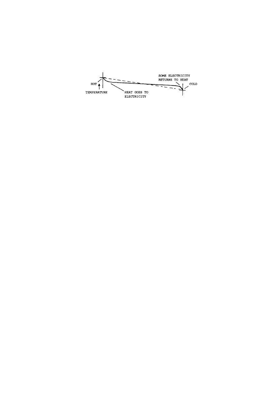
38
©
HAROLD ASPDEN, 1994
ENERGY SCIENCE REPORT NO. 2
unity. However, we had a system in which the temperature was changing much as depicted
in Fig. 5.
Fig. 5
The dotted line represents the linear temperature profile and the curve the profile we
are exploiting. β is a measure of the conventional temperature gradient of the dotted line as
a ratio to the minimal temperature gradient midway between the junctions. The latter is a
measure of the heat energy going to waste and the much larger gradient of the full curve at
the hot junction is a measure of the heat energy entering the device before conversion into
electricity. Because the midway gradient is much lower than the linear case, we have a high
β factor and because it is very much lower than the input temperature gradient we have a
very efficient device capable of taking in far more heat than a conventional device.
I believe that I have said enough to outline why the Strachan-Aspden thermoelectric
power converter works so well. The ongoing research relates to how far we can compromise
on the thin film factor γ with a view to using thick metal layers and relying exclusively on
the β factor of the transverse commutation feature. Unquestionably, our primary products
will use the dynamic excitation feature to get the advantages of power from base metals, but
we foresee also the use of special metals as well, coupled with designs based on the β factor.
I should like to end by describing how, even before we filed our first patent
application or got involved commercially, we got a measure of the β factor applicable to our
first demonstration device. Very simply, we had built a small panel having metal faces and
layers of thin metal film rnning from face to face but embedded in an insulating dielectric.
Looked at in the direction of heat flow, the metal and dielectric were side-by-side, with the
metal presenting a cross-section amounting to about one five hundredth of that of the
insulator. Such a device, therefore, was not, in thermal conductivity terms, a through-metal
conductor.
To get a measure of its properties, we put an ice cube of standard size on the upper
metal face and attached the lower face to a commercial heat sink base at room temperature.
The ice melted, partly by heat absorbed by air convection from above, partly by heat loss
by thermal conduction through the intervening insulation and partly by heat conduction
through the metal. It took in excess of 20 minutes to melt completely. This was with the
output leads from the device unconnected, that is, on open circuit. I knew from a test at
home that such an ice cube on a metal work surface took about 5 minutes to melt and took
30 minutes on a Formica-topped kitchen table. The point of interest then was that when the

39
©
HAROLD ASPDEN, 1994
ENERGY SCIENCE REPORT NO. 2
same sized ice cube was used on the device with the output leads connected to an electric
motor or a resistor load, the time of melting reduced to between 3 and 5 minutes. The motor
stopped running, of course, soon after the ice had completely melted, but the message from
these very simple measurements was clear testimony of a very high internal efficiency in the
generation of electricity from heat. There being no independent electrical power supplied
to the device and the ice being the only perturbing influence, the connection of the electrical
load had diverted more than 80% of the heat energy around the wired load circuit and this
was via a capacitance. That 80% and more of power was electrical power and most of the
other 20% of heat conduction was seemingly unnecessary loss because much of it was due
to extraneous convection or heat conduction through what was unnecessarily thick dielectric
insulation.
It was from such a very simple test that we knew the β factor had to be 10 or more,
but we were carried along by that empirical performance and, may I say, that was so high
that, for a time until we could make more precise measurements, mainly of temperature, we
thought we had achieved the impossible, by going above 100% of Carnot efficiency.
As it is today, in our best performing thin film prototypes we still have difficulty
measuring just how close we are to the ultimate Carnot efficiency.
Concerning thick film designs, which do not have the high thin film conductivity
feature, our research is progressing in sustaining the themoelectric voltages achieved by the
DYNAMIC EXCITATION FEATURE and exploiting the β gain by the use of the
TRANSVERSE COMMUTATION FEATURE."
**********
Concerning the latter comment about thick films, this was a theme which this
author (H. Aspden) urged at the time (October 1989), but this was shortly before the
R & D funding ceased and the test facilities closed when the other business interests of
the sponsors failed.
This author did, independently, seek to experiment with a small test unit in
which thin nickel plates plated on both sides with copper were bonded into an integral
assembly for resistance testing. It did not function as hoped when subjected to a small
temperature differential.
However, this was a first attempt at a time when thoughts were on the collapsing
sponsorship and it later became evident that the test external circuit facility used lacked
the necessary current capacity to cope with current oscillations at the requisite
frequency and strength.

40
©
HAROLD ASPDEN, 1994
ENERGY SCIENCE REPORT NO. 2
The test apparatus used was also unable to sustain a significant temperature
gradient in the metal owing to metal thickness being too large and it had, at the time
not occurred to this author that it would have been better to drive a moderate current
oscillation through the structure and look for a cooling effect attributable to the Nernst
action.
Evenso, in this latter regard, the nickel sheet material used in these experiments
would, with its copper plating, have posed the same problem that has now (1994) been
encountered in a much larger test device, namely the fact that a multiple bimetallic
interface in a series circuit can, without an initial temperature gradient to prime the
action, avoid the Thomson Effect current diversion and thereby generate junction
heating that is not segregated from the Peltier cooling.
The author's current research which will be described in Energy Science Report
No. 3 is now directed along a track which aims to overcome these particular problems
in an effort to avoid transverse current excitation through a dielectric medium whilst
constraining heat flow to be transverse to the current and EMF attributable to the
Nernst Effect.

41
©
HAROLD ASPDEN, 1994
ENERGY SCIENCE REPORT NO. 2
APPENDIX IV
The Strachan-Aspden Invention: Test Results
[October 1989 Report]
This report is a copy of the TEST REPORT presenting the status of the
Strachan-Aspden Energy Converter project on 19th October 1989, as
included in the 23rd October 1989 document.
Introduction
The device tested was built expressly to verify design criteria, essentially to check
that we were right in eliminating certain design features present in the first demonstration
device. The tests confirm our theoretical assumptions.
In order not to alter too much in this stage of development, the same commercial
bimetallic coated dielectric was used and the same physical dimensions of the thermocouple
junction interfaces. These are not optimum, particularly concerning thickness of metal layers
and possibly concerning choice of the actual metal combination as well as the length
dimension between the thermal surfaces.
However, whereas the operating frequency was 500 kHz with the first device, the
present device runs at 18 - 25 kHz, depending upon load and voltage output rating. Such
frequencies impose design constraints, which will not be a problem if we can build a non-
capacitative device now predicted as a possibility using the verified design principles.
The primary objective of the tests reported here is not to see whether the efficiency
of the device assures its commercial viability as it stands, because we can certainly design
to achieve a far better power rating and a simplified technique of fabrication. The objective
is to measure the efficiency of the device for operation over a moderate range of ambient
temperature, with atmospheric, geothermal and waste heat in mind as energy sources.
The measure of efficiency and study of factors affecting efficiency are vital to
projecting commercial applications and designing products for manufacture, especially
concerning the Peltier mode for refrigeration and cooling and also for conjecturing products
which store electrical energy as heat and regenerate electricity. The use of plastic film as
a substrate for the bimetallic layers has limited the temperature range of the particular device

42
©
HAROLD ASPDEN, 1994
ENERGY SCIENCE REPORT NO. 2
tested. Also, owing to the specific form of the electronic switch system built for the device,
tests in the refrigeration (Peltier) mode did not prove viable for reasons in no way related to
the device structure and measurements of efficiency of Peltier mode operation have been
deferred.
An overall performance figure, allowing for all circuit losses and output voltage
transformation, which can be relied upon for conversion of heat to electricity with
temperature differentials as low as 10 to 30 degrees Centigrade is 70% of Carnot efficiency.
The Structure of the Test Device
The device is constructed from 300 layers of 28 micron thick high dielectric constant
plastic film as a substrate for sputtered junctions of two layers of metal, nickel and
aluminium. Each layer had a width of 3 cm and a length of 0.25 cm, the width dimension
and edge forming the surface interfacing with the heat exchange surfaces. The aluminium
film was 0.02 micron thick and the nickel film 0.04 micron thick.
These 300 layers therefore defined 300 junctions each having exposure to a hot and
a cold face of the panel form of the assembled device. These were divided into 20 groups
of 15, each group comprising 3 sub-groups of 5 layers. Each such sub-group is bounded by
a layer of copper as an electrode for wiring the device into the chosen series/parallel
configuration. Thus, in effect, there were 15 layers stacked to form a series capacitor unit
and 20 such units were wired together to form a parallel connection of the capacitor units,
ultimately having connection to an external circuit by two supply wires.
The copper electrodes were narrower than the junction length to reduce their thermal
conduction contribution to the heat path. The entire stack of 300 junction layers was bonded
on to a ceramic powder composition base to give good heat coupling but to ensure electrical
insulation from the heat sink base an upper aluminium sheet was bonded by an electrical
insulating heat sink compound to the upper surface of the stack to form the other external
heat surface.
When a temperature differential is set up between these external heat surfaces there
is a thermoelectric charging of each junction which contributes to the energy storage in the
capacitor stack. Indeed, as a function of the temperature differential, the capacitor so formed
has a greater effective capacitance than would be expected purely from calculation based on
the dielectric constant and dimensions of the assembly. Typically, the capacitance can be
of the order of 1.5 microfarad for this very compact assembly.
The thermoelectric current acts to sustain the recharging of the stack as it is
systematically charged and discharged by a fast operating switch unit. For the test to be

43
©
HAROLD ASPDEN, 1994
ENERGY SCIENCE REPORT NO. 2
described this unit comprised five electronically controlled switches operating in parallel
expressly to ensure that there is a minimal loss of electric potential, inasmuch as the EMF
of a mere 15 junctions was being switched. The control of this switch bank involved a
frequency generator input of negligible power. Note that it was a specific feature of the first
prototype test device that it included a self-activated oscillator for switch control powered
by the electric signal generated by the device.
The action involved, therefore, can be seen as one involving deploying thermoelectric
power into the charging of the capacitor stack and then, as fast as possible having regard to
the recharging speed, transferring the stored energy to an output circuit by a cyclic switching
operation. Subject to the capacitative delays and charge storage aspects, the action can also
be seen as one involving circulating thermoelectric currents in the bimetallic layers with a
superimposed transverse current flow through the capacitor.
A high Q transformer winding is intermittently connected to the stack via the
switches. This presents a low impedance into which the capacitor stack drops its
thermoelectrically acquired charge. The secondary winding of the transformer then
transforms the resulting voltage to a value which matches well with the load, both to give
suitable measurement voltages and also to ensure that the load seen by the stack has a
sufficiently low impedance to draw out the charge quickly. Note that the device has its own
internal resistance and the load resistance has to draw most of the power.
Measurement Criteria
The device tested is a flat square metal-faced unit which has a pair of electrical
input/output leads. Given a temperature differential across its metal faces an electrical
power output is available. In terms of the heat input, this electrical output depends (a) upon
the internal design structure of the device (which cannot be varied as part of the test) and (b)
upon the manner in which the load circuit is electronically controlled. The latter control,
though as just described working successively to charge and discharge the capacitor form of
the device, also implements what we term 'dynamic current excitation' and this greatly
enhances the power output. The A.C. power supplied is converted to D.C. and smoothed
for measurement. The performance depends upon matching the load with the device to
secure optimum output.
Basically the test to be reported is very simple. By feeding in a sustained amount of
heat, controlled by electrically powering a small resistor in a liquid heat bath, the task is to
reconvert some of that heat back into electricity as D.C. in an output load at a steady voltage
and current. This will give basis for precision tests on power in and power out, but to assess
the result obtained it is important to have a very good measure of the temperatures of the two
metal faces. The temperature measurement poses problems, because, firstly, we must beware

44
©
HAROLD ASPDEN, 1994
ENERGY SCIENCE REPORT NO. 2
of any non-uniformity of temperature across the operative surfaces and, secondly, we must
know the extent, if any, of any interference caused by the measuring device or probe.
Earlier test results had been clouded by the problem that the bounding 1 mm thick
aluminium plate was not able to buffer the heat distribution to assure a uniform temperature,
given a concentrated heat source (electrically energized carbon resistors) on the external
face.
For this reason the initial measurements on the device described, which were
unreliable in ranging from 50% to 100% of Carnot efficiency, according to test conditions,
have been repeated using a stainless steel can containing water heated internally by a chain
of four 10 ohm resistors. This can was specially built with a flat lower surface able to
interface well with the heat surface of the device and was mounted thereon using heat
conducting paste. Also, the whole structure was housed in a close fitting heat insulating
container.
The temperature measurements involved calibrated platinum resistance probes
registered by a digital voltmeter and were from time to time confirmed with an alcohol
thermometer.
Peripheral Test Information
It was not part of the test reported here to repeat certain experiments that were made
in the earlier development stages. Nor could we measure directly the thermoelectric EMFs
in the sections of the stack built into the device. During construction it was part of the
discipline of the assembly procedure to test each part-assembly of five junction layers to
verify insulation and be sure that it was performing with the power of 2 millivolts per degree
Centigrade when subjected to dynamic excitation. Any that did not match the uniformity
requirements were rejected. However, as will be seen, the test data do tell us that this
thermoelectric EMF is at work in the operating device because the output EMF from a stack
is measured and the voltage at the output terminals is roughly equal to the internally
produced thermoelectric EMF times the measured efficiency relative to the Carnot limit.
This also means that the current output as a measure of junction current relates by this total
thermal power to the potentials active at the junctions and so gives a measure of the
thermoelectric power in the device.
This thermoelectric power is the crucial factor in our onward design of any products.
It was 400 microvolts per degree Centigrade per junction pair in the above device and this
applied to the thin film (0.02 micron aluminium on 0.04 micron nickel) assembly. The two
metals had no intervening metal; they were vapour deposited. In contrast, earlier tests had
shown that a stack of metal plates of iron and nickel of sub-millimeter thickness with
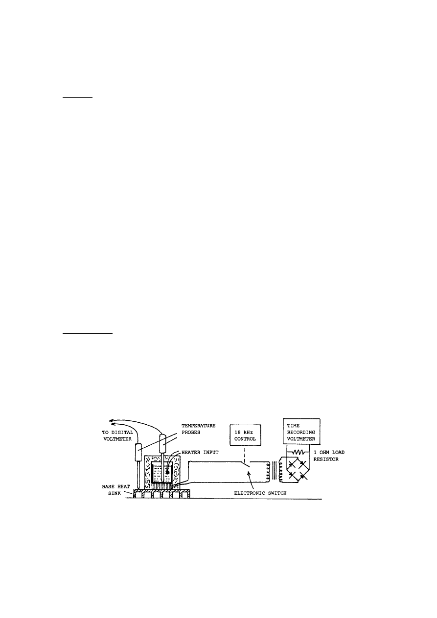
45
©
HAROLD ASPDEN, 1994
ENERGY SCIENCE REPORT NO. 2
soldered junctions gave a thermoelectric power per junction of 118 microvolts per degree
centigrade with dynamic current excitation. Given that we can reasonably expect iron and
aluminium to present similar thermoelectric action when forming junctions with nickel, the
question we need to resolve is whether that gap between 118 microvolts and 400 microvolts
is due to the thin film aspect in the vapour deposited case or the adverse effect of the
intermediate solder in the thick film test case.
The most important test data of interest, therefore, at this time and before products
are designed and manufacture evaluated, are
(a) the actual efficiency for limited ambient temperature use of the device already
constructed, and
(b) the thermoelectric power of a thick metal junction assembly with no solder connections.
This report addresses the first of these issues and the next report will deal with our
findings on the other question.
The onward test programme must relate to the factors such as optimum film thickness
and dielectric thickness in the vapour-deposited/capacitor system or thickness of a thick film
version, optimum electronic design and excitation frequency as well as waveform profiles,
choice of metals, structural dimensions (panel thickness) and electrical insulation/heat
conducting spacing material at the interface of the external metal surfaces and the junction
assembly.
The Test Data
These tests were performed independently by Scott Strachan and Harold Aspden
during different periods in October 1989.
The Strachan tests were performed between 10th October and 12th October. The test
results obtained by Aspden on 17th and 18th are those listed in Tables II and IV.
The test apparatus is as shown in Fig. 1.
Fig. 1

46
©
HAROLD ASPDEN, 1994
ENERGY SCIENCE REPORT NO. 2
Application of heat energy is via the medium of heated (or cooled) water in a
container on the upper heat exchange surface and use of a commercial heat sink base at room
temperature replicated conditions which would apply to production devices. The cold
underside can be considered to be at an even temperature because it is mounted on a massive
heat sink with a recognized high heat dissipation capacity.
The water heat sink provided a uniform temperature interface and this temperature
was measured by a commercial platinum resistance temperature probe calibrated to give a
measure of temperature via a digital voltmeter. A similar and separate heat probe was used
to measure the temperature on the surface of the base heat sink.
Owing to heat transfer through the device, albeit mainly via the electrical conversion
route, as Peltier cooling occurs at one face and Peltier heating at the other, it is inevitable that
the actual temperatures at the working interfaces of the device will be slightly lower than the
hot temperature measured and slightly hotter than the cold temperature measured. This
means that the true efficiency relative to Carnot will be just a little greater than that
calculated using the measured temperatures. No allowance is made for this in the test data,
because the temperature drops involved would be present in an engineered installation and
so the test results give an overall measure of effective efficiency which can be regarded as
representative of commercial conditions.
Preliminary Tests
The following tests were conducted under steady-state conditions, that is, the rate of
heat input was pre-set and temperature readings as well as electrical power output readings
were made only after the system had stabilized.
TABLE I
TEST HEAT INPUT
OUTPUT TO 1 OHM TEMPERATURE EFF.
No.
Volts Amps Watts
Volts Watts
T'
T
%
1
6.64
0.179 1.19 0.125 0.016
33.8
20.0
30
2
9.16
0.244 2.23 0.280 0.079
40.4
20.6
56
3
11.22 0.298 3.34 0.450 0.202
47.5
20.8
73
4
12.60 0.337 4.25 0.520 0.270
53.4
21.0
64
5
19.00 0.530 10.07 0.720 0.518
62.2
23.0
44
**************
The above readings were the first set of readings to be made on the device under
proper laboratory test conditions using electronic test circuitry that was designed to operate

47
©
HAROLD ASPDEN, 1994
ENERGY SCIENCE REPORT NO. 2
essentially with power output voltage above 0.3 volts, which is a nominal threshold for
effective operation of the germanium diodes used to rectify an A.C. output. For this reason,
attention centres on tests No. 3 and 4. Concerning test No. 5, this fell short in measuring true
efficiency for reasons to be discussed below, owing to a heat dissipation problem which set
in above 55 degrees Centigrade and upset the measurement on the input side.
Immediately, however, one can verify the design assumptions by considering the
ideal 100% of Carnot condition if applied to test No. 3. This would require all the heat
energy input at the hot side to convert to electric power given by Nπi, Where N is the number
of junctions (300), π is the Peltier coefficient αθ and θ is the temperature of the hot junction
in Kelvin (320). With α as 400 microvolts per degree, this gives an input power of (38.4)i
watts. Now, i is the junction current and we regard this also as external current, subject to
allowance for the series/parallel junction combination and the transformer ratio. In effect,
therefore, the 100% of Carnot situation can only occur if the heat power supplied at 320K
is precisely such that it is 3.34 watts, which corresponds to a junction current of 87
milliamps. This flows in each of 20 parallel circuits to suggest a total current of 1.74 amps
would suffice to carry all the heat input through as electricity.
This checks with the measured current of 0.450 amps if allowance is made for the 5:1
transformer ratio. In fact, this measure is 2.25 amps compared with 1.74 amps needed for
100% efficiency and this is 77% agreement (cf. the 73% of Carnot efficiency measured).
This is very good agreement, also bearing in mind that the 400 µV/K thermoelectric power
can be effectively diminished by parasitic current flow owing to the 20 parallel-connected
circuits in the device and may need some offset for the partial action of the component added
by the Thomson effect. The latter does not contribute to the Peltier heating and cooling at
the junction proper, but does drive current as part of the thermoelectric power.
The measurements of current output in relation to heat input fit remarkably well and
confirm the high thermoelectric power, α of 400 µV/K, that had been measured on a test
basis as each five-junction part-assembly was built into the device.
It had been foreseen from theory that about 260 µV/K would be true thermoelectric
power and about 170 µV/K could be due to Thomson effect. Therefore, a 60-70% effciency
factor might imply a measured output voltage of the order of 250 µV/K. In test No. 3 the
0.450 volts came from a 26.7 degree differential and 15 junctions in series with a 5:1
transformer ratio. This works out as a junction EMF of 225 µV/K.
Concerning the drop of efficiency as more heat is fed into the device (test No. 5) it
is found that the apparatus begins to lose heat from evaporation as bubbles form around the
heater. This loss of heat is such that the apparent performance drops appreciably with
increasing temperature. However, this is an artefact of the way in which the heat input is
measured by the electrical heating of water. Evaporation on the input side of the device

48
©
HAROLD ASPDEN, 1994
ENERGY SCIENCE REPORT NO. 2
cannot be a fair factor in the test, which is only viable provided bubbles are not formed in the
test heat input source or the latent heat carried away by those bubbles is somehow accounted
for.
Load resistance versus internal resistance
The value of the load resistance, given a variable heat input rate, is an important
consideration. The heat input determines the operating temperature and this, in its turn,
determines the output EMF. The load resistor and this EMF determine the current output,
but for optimum operation it is necessary for this current output to be the full junction
current. It is possible for some junction current to be internally diverted by closed loop
circulation between the metals forming a bimetallic layer. Such circulation would transfer
energy from the hot to the cold junctions without the Carnot component being diverted for
use in the external load circuit. However, the test bears out an assumption which emerged
in the development of the 'cold spot' theory of the device. The expectation from this was
that, at least when operating in the Seebeck mode under test, the dynamic current excitation
developing the enhanced thermoelectric power would drive the junction current exclusively
through the external circuit. On this basis, the only load matching consideration is how the
internal resistance of the device relates to the load resistance in contributing to ohmic losses.
For the 1 ohm load condition of test No. 3 we can interpret the output of 0.450 volts
as a measure of 0.090 volts on the input side of the 5:1 transformer. This is the output of 15
junction pairs and, for the temperature differential of 26.7 degrees, it implies that a
thermoelectric power of 225 µV/K has reached the load circuit. Bearing in mind that a 400
µV/K thermoelectric power is known to be potentially active and that the 1 ohm load is a
0.04 ohm load on the input side of the transformer (owing to the squared effect of the 5:1
transformer ratio), this suggests that the internal load resistance is 0.03 ohms if there is no
loss of potential. A value of 0.02 ohms is calculated from knowledge of the resistance of the
commercial material used to build the device (see comment on this which follows) and this
is probably the true value. Such resistance applies if virtually all the external current is
flowing by snaking action through the thermoelectric junctions with very little internal closed
loop flow detracting from that performance. These considerations tend to confirm the design
assumptions used.
The internal ohmic heat loss is then estimated from the measured external current
0.450 amps, which scales to 2.25 amps for the input side of the transformer and this current
in 0.02 ohms implies an ohmic heat loss of 0.10 watts.
This can be reconciled with the 0.202 watt output with an estimated 70% of Carnot
efficiency, much as is deduced for test No. 3, especially as some of the ohmic heating at 0.10
watts is available for regeneration of electricity.

49
©
HAROLD ASPDEN, 1994
ENERGY SCIENCE REPORT NO. 2
This discussion really aims to assess the scope for increasing efficiency further by
future design which reduces internal resistance, it being important to understand the factors
affecting performance in the design under test.
It now remains to reconcile the relatively low efficiency of test No. 1, for example,
with that of test No. 3. This is easily explained simply because the germanium diodes used
in the bridge rectifier connected to the transformer output absorb energy, becoming good
conductors only as the forward voltage across them rises above 0.3 volts. This will present
no problem in production thermo-electric devices because many more junctions than 15 will
be connected in series and this will result in high performance relative to the Carnot limit,
even with the low temperature differentials represented by test No. 1.
However, in the verifying tests to be reported below, this will be checked in view of
the importance of applications working with quite low temperature differentials.
Calculation of internal resistance
The efficiency necessarily depends upon the internal resistance of the device. This
may be calculated approximately using the fact that the 0.1 ohm per square specification of
the bimetallic layer arises from parallel flow through 0.2 ohm per square of nickel and 0.2
ohm per square of aluminium. The device involves series flow through 300 bimetallic layers
of width 3 cm and length 0.25 cm, but the current will not follow the longest route. This is
somewhat less than 0.03 ohms per layer. The layers were connected 15 in series and 20 in
parallel and this implies a total internal resistance somewhat less than 0.75 times 0.03 ohms
or, say, 0.02 ohms. This is the value estimated from the measurement data reported above.
Verification Tests
These tests were performed by H. Aspden on 17th and 18th October. The first set of
tests reported in Table II concentrated on the peak range of efficiency indicated by Table I.
It was found that even a small change of heat input rate meant waiting for between 20 and
30 minutes to secure temperature equilibrium. The latter is vital to proper measurement of
temperature. The temperature readings are believed to be correct to within 0.05 degrees
Centigrade and, as far as can be judged, any error from making measurement at a surface
point slightly offset from the actual operative thermal interfaces would mean that the
efficency values obtained are 'worst case'. It is, therefore, felt that the efficiencies now
registered are reliable in indicating what can be achieved in a commercial installation.
TABLE II
TEST HEAT INPUT OUTPUT TO 1 OHM TEMPERATURE EFF.
No. Volts Amps Watts
Volts Watts
T'
T
%

50
©
HAROLD ASPDEN, 1994
ENERGY SCIENCE REPORT NO. 2
6
9.50 0.253 2.40
0.300 0.090
41.9
18.6
51
7
10.00 0.266 2.66
0.340 0.116
42.8
18.8
57
8 10.50 0.279 2.93
0.375 0.141
45.1
19.3
59
9
12.00 0.318 3.82
0.490 0.240
49.4
20.2
69
10
13.00 0.345 4.48
0.545 0.297
54.0
20.6
65
11
14.00 0.371 5.19
0.565 0.320
55.0
20.9
59
These tests reported in Tables I and II are characterized by the use of electrically
heated water as the thermal input source, as opposed to an electrically heated metal interface.
The object was to get more uniformity of temperature and so a precise indication of the true
temperature. However, above 55 degrees Centigrade the water loses heat rapidly owing to
vaporization and then the measure of heat input rate fails to indicate true efficiency.
The tests certainly reveal that efficiency of heat to electricity conversion of 70% of
the Carnot level is a reasonable expectation with temperature differentials in the 30-40
degree range close to ambient conditions, but this is further supported by the tests in Table
IV.
Based on test No. 10 a check was made of the effect of changing the dynamic
excitation frequency. The operating frequency for the data in Tables I and II was 18 kHz.
This had been chosen for optimum tuning of the circuits. As might be expected, there was
a drop off in efficiency with reduction of frequency. The data given in Table III apply.
TABLE III
TEST FREQ. THERMAL INPUT
POWER OUTPUT TEMPERATURES EFF.
No. kHz
Watts
Volts Watts
T'
T
%
10
18
4.48
0.545 0.297 54.0 20.6 65
11
14
4.48
0.530 0.281 54.0 20.6 61
12
10
4.48
0.495 0.245 54.0 20.6 53
************
This test does not mean that the frequency has to be of the order of 18 kHz to obtain
the highest efficiencies from the dynamic excitation. It is just that the capacitor structure of
the particular test device with its transformer inductance and self-inductance has an optimum
switching frequency. A problem ahead is to assess the best frequency for dynamic excitation
giving the highest thermoelectric EMFs and then design the device so that the capacitance
and inductance match this operating frequency.
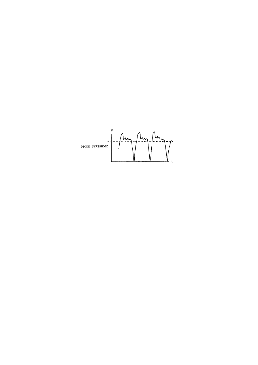
51
©
HAROLD ASPDEN, 1994
ENERGY SCIENCE REPORT NO. 2
The next set of experiments involved a change in the transformer from the one used
in the above tests which had a 5:1 ratio to a new one with an 8.5:1 ratio. This required a 25
kHz excitation frequency for best response, owing to the change in inductance on the primary
side.
The object of this change was to explore the loss of output power for very low
temperature differentials, which loss resulted from a threshold cut-off in the germanium
diode bridge rectifier circuit used to produce smoothed D.C. from the transformer output.
The problem faced was due to the A.C. output waveform being of the form shown in Fig. 2.
As the signal amplitude increases, more and more of the signal rises above the operating
threshold of the diodes and, to get a realistic efficiency measure, substantially all of the
signal has to lie above the threshold.
Fig. 2
The sole purpose of the following tests in Table IV was to check to be 100% sure that
we still have an efficient converter using the temperature differentials of Test No. 1. This
test has given 30% of Carnot efficiency with a 13.8 degree differential but the output voltage
was below the diode threshold for a significant part of the dynamic excitation cycle. By
stepping
TABLE IV
TEST HEAT INPUT OUTPUT TO 2 OHM TEMPERATURE EFF.
No. Volts Amps Watts
Volts Watts
T'
T
%
13
8.48 0.226 1.92
0.400 0.080
38.3
18.8
66
14
6.20 0.168 1.04
0.255 0.032
32.8
18.8 67
*************
the voltage output up by the greater transformer ratio, a greater portion of the signal becomes
effective in overcoming the bias in the diodes.
These data clearly show that the comparable results for tests Nos. 1 and 2 suffer from
the diode cut-off, that the problem has been easily overcome by output circuit redesign and

©
HAROLD ASPDEN, 1994
ENERGY SCIENCE REPORT NO. 2
that efficiencies of 66% plus relative to the Carnot level are to be expected as the operating
norm of the Strachan-Aspden converter, even when the temperature differential is only a few
degrees.
Tests using iced water
It was possible to cool the heat sink base by immersion in a tray of iced water and
hold the upper heat surface of the device at ambient temperature. The results (power output
for a given temperature differential) were fully in accord with the performance just reported
for similar small temperature differentials. The ice test of the first prototype device holds
up in that electricity can be produced by melting ice. Such tests, however, do not give a
measure of efficiency because the rate at which the ice is melting is difficult to measure.
However, the efficiency must be as indicated in the tests of this report, because the device
and its circuit only 'see' temperatures at the working heat surfaces.
Conclusions
The tests reported above are definitive tests on a Strachan-Aspden device using thin
film thermoelectric techniques with dynamic excitation and transverse commutation in a
capacitative assembly.
The tests aimed at determining efficiency. The efficiency results were typically 65-
70% of Carnot level for differentials of temperature in the ambient range. The power rating
measured in heat throughput rate was 2 kilowatts per square meter for a 20 degree
temperature differential. The corresponding electric power generation with this very low
temperature differential is 80 watts per square meter. However, efficiency, rather than
throughput power, was the purpose of these tests and it is important to remember that the
working metal involved in the test device is interfacing over only one part in 1000 of the total
area of the heat input surface. As we adjust the metal film thickness relative to the dielectric
and conceivably eliminate the dielectric, the full design potential can be exploited. It is such
that the technology of the device can cope with any practical level of heat input per unit area
that available heat sources (or heat transfer materials) can supply at the operating
temperatures specified.
Concerning tests in Peltier mode, meaning input of electricity to cause heat transfer
between the heat surfaces, this was not possible with the specific design of excitation control
circuitry of the device just tested. The first prototype incorporated a self-tuning circuit which
could adjust to give the best dynamic switching rate.
Such tests will be performed but until they have been performed either on the subject
device or other implementations we cannot pronounce on the efficiency for Peltier mode
operation. Our feeling is that it will be high, but perhaps not as high as for electrical power
generation in Seebeck mode. However, high efficiency is more important for electrical

53
©
HAROLD ASPDEN, 1994
ENERGY SCIENCE REPORT NO. 2
power generation applications and an outlook of 70% of Carnot with more expected from
production designs is very good indeed.
Footnote
Much of the research effort between February 1989 and July 1989 involved efforts
to fully understand the relative roles of the factors which contributed to the working of the
first prototype. It was a set back that an attempt at partial reassembly of that device to test
efficiency had caused its destruction by internal shorting owing to chemical penetration.
However, the new device, built in July-August 1989 period and modified according to the
results of that research, now verify the design assumptions and have yielded the efficiency
data. Thick-metal-film test converters are now under construction and once the tests on these
are complete we will be in a position to project how best to proceed to a product stage.
Our patent position has been brought into line with these recent findings so that our
main international cover will relate directly to design variations centred on the structure
incorporated in the test device discussed in this report. Such cover also caters for what is
expected to be a successful outcome on the thick-film embodiments.
H. Aspden: 22nd October 1989
************
The above test report describes the status of a research test at a time when the
interest centred on measurement of efficiency. In the diagnostic research phase which
followed it was realised that there was a gain in performance that came from the
Thomson effect driving current along the thin film by heat action. One did not need to
generate electricity to sustain the full measure of current flowing and thereby eat into
some of the useful power generated.
The problem, however, with the capacitative device was that the transverse
current carried through the capacitor stack which was powered directly by the Peltier
EMF was no doubt a distributed current across the section of the stack. In this case the
capacitor implementation must involve joule heating owing to some current flow in the
thin section of the metal film, as allowed for in the above analysis.
However, then the current traversing the junctions in the transverse direction
is not concentrated at the edges of the bimetallic layers, as it could be in a modified non-
capacitative implementation. The actual efficiency of the capacitor device found under
these circumstances is quite remarkable and is at the limit of the what is conceivable
from Peltier action owing to the temperature profile across the junction interface. Bear
in mind that the temperature governing the Peltier action is not exclusively that at the

54
©
HAROLD ASPDEN, 1994
ENERGY SCIENCE REPORT NO. 2
edges. This suggests that there is some other action involved in the device which
contributes to enhancing the efficiency.
Research into this question points to a thermal feedback effect connected either
with the Nernst Effect or with free electron diamagnetism, meaning a
thermodynamically powered gyromagnetic reaction set up in conduction electrons in
metals in opposition to the magnetizing effect arising from the Thomson effect
circulating currents in the metal films.
The updating of this research report will therefore need to examine the
theoretical factors involved and the very different design considerations which apply
if one makes connection between the bimetallic films by metal conductive edge contact
only, without the circuit path being through charge oscillations in a capacitor dielectric.
Such a report update also may need to include an examination of the research
implications if one designs the converter to over-excite the thermal feedback action,
assuming that such an action is really adding to that efficiency. In principle these later
developments point to a very much greater performance potential, having regard to the
fact that we are exploiting temperature gradients in metal with transverse current
excitation and not a power current flow through metal directly between junctions at
different temperatures.

55
©
HAROLD ASPDEN, 1994
ENERGY SCIENCE REPORT NO. 2
( kT
e
)log( n
)
n
)
(2)
APPENDIX V
The Stachan-Aspden Invention: Thermodynamic Power Anomaly
[October 1989 Report]
D.C. THERMOELECTRIC POWER ANOMALY
The Strachan-Aspden invention shows that thermoelectric EMFs far greater
than are expected from conventional textbook data are effective with A.C.
operation. The reason for this needs to be understood in order to give one a
measure of confidence in advancing the R & D effort needed to exploit this
newly-discovered phenomenon.
The following scientific paper, which has not been published elsewhere, deals
with this question.
ABSTRACT
The discrepancy between the theoretical and measured thermoelectric power
of bimetallic thermocouples is explained on the assumption that current flow
across the junction occurs in filamentary surges which concentrate the
heating and cooling effects and so distort the effective temperature
differential. The basic theory used conforms with that of more classical
treatments, inasmuch as modern theory has adapted to cope with
semiconductor materials which exhibit temperature effects quite different
from those found in base metals.
******
The theoretical thermodynamic value of the Peltier coefficient is shown by Ehrenberg
[1] to be:
where k is Boltzmann's constant, T is the junction temperature, e is the electron charge and
n', n are the population densities of the free electrons in the two metals forming the junction.

56
©
HAROLD ASPDEN, 1994
ENERGY SCIENCE REPORT NO. 2
The thermoelectric power of an individual junction is the same expression without the T
term, being an EMF per degree of temperature.
In Table III of this Ehrenberg text [1] a tabulation shows the measured values of the
thermoelectric power for various base metals referenced on the metal sodium. The data show
that the discrepancy between the caluculated and measured values is a factor of 15 for Ag
and Au, a factor of 21 for Cu, 51 for Al and 6 for Ni. Ehrenberg also deduces theoretical
values for the Thomson coefficient, which makes an additional contribution to the
thermoelectric effect and is a function of the rate of change of free electron density with
temperature. Ehrenberg does not compare theory and experiment in this case.
In view of the potential benefits of efficient thermocouple devices in refrigeration
avoiding the use of polluting CFC chemicals, there is now a pressing need to understand the
fundamental reason for this discrepancy. The following investigation is part of an ongoing
commercial research study into this problem, which has already revealed techniques by
which to close the gap between the calculated and measured thermoelectric power,
particularly for an Al-Ni thermocouple.
Equation (4) is derived on the thermodynamic assumption of a thermal pressure
balance as between electrons in both metals. If, as with certain semiconductor thermocouple
junctions, there are positive (p) and negative (n) charge carriers in the different conductors,
the Peltier coefficient need not depend upon the ratio of carrier densities. If p-n annihilation
occurs at one junction and p-n creation at the other, the current-related thermodynamic
energy exchange is more consistent with a thermoelectric power corresponding to a Peltier
coefficient of 3kT/e. Upon annihilation, for example, two carriers merge, each transferring
its individual thermal energy 3kT/2 into electrical power, and so developing a net EMF E
related to an energy Ee equated to 3kT.
For the Al-Ni combination, using equation (4), Ehrenberg [1] assumed a carrier
density ratio of 21, which gives a logarithmic factor of 3.04. This implied a thermoelectric
power of 265 microvolts per degree centigrade. Since then, however, carrier polarity data
for the Hall effect, as revised, suggests that the Al-Ni thermocouple may have a
thermoelectric power related to the p-n condition, which coincidentally gives virtually the
same value. Thus, the very substantial discrepancies between observation and theory noted
by Ehrenberg still apply, even for this Al-Ni metal combination.
It is possible that, though a predominant free electron population exists in a metal
conductor, the electrical conduction properties are not, at every instant, related to the shared
action of all the electrons. Imagine, for example, that the charges carrying current tend to
concentrate their ordered motion collectively into a transiently relocating filamentary in-line
flow through the conductor. This filament, which may comprise short and transiently
discontinuous current elements, corresponding to charge concentrations, breaks up to be

57
©
HAROLD ASPDEN, 1994
ENERGY SCIENCE REPORT NO. 2
replaced by another such filament elsewhere so that, on average over a period of time, the
flow appears uniformly distributed across the section of the conductor. In a sense, this
physical picture is easy to justify because the electrons following at speed in the same
direction along a common line, one behind the other, are less likely to be scattered by
collisions.
Of course, such speculation has little value unless supported by tangible evidence.
Force-free vortex filaments which appear on a nanosecond time scale feature in plasma
research [2] and have led to analysis of the density and velocity distribution profiles of
electrons and positrons in filaments [3]. However, so far as solid conductors are concerned,
this filamentary action is not something that can easily be established. It may emerge from
research into the properties of 'warm' superconductors or from research on the thermoelectric
anomalies under discussion.
Firstly, with the plasma aspect in mind, it is known that the arc discharge in mercury
arc rectifiers develops discrete cathode spots on the surface of the mercury pool. This means
that the current divides into separate flows. These spots meander around but there is some
mechanism by which the discharge breaks into discrete filaments of the order of 15-20 A in
strength, as if this represents some critical current factor defining a single current filament.
Secondly, extensive researches by Hildebrandt [4,5] have shown that current as high
as 30-40 A will divide between two separate anode-cathode discharge paths, with anti-phase
modulation at a period of 15 ns, and that this effect is not caused by resonant circuit
properties but is an inherent property of the conductive medium. Thus, in a plasma at least,
this is consistent with a preferred filamentary current state in which the carrier flow is
involved in what may be termed an 'inverse avalanche effect' as the conduction action
concentrates into fewer carriers in a filament with a 15-20 A critical maximum current for
continuous in-line flow.
It is now noted, without particular elaboration, that if a train of electrons form in line
at equal spacing and move together to convey current along that line, then, if each one steps
forward to the position of the electron ahead at the Compton electron frequency, the current
carried is 19.79 A. This is simply ec/λ
c
, where e is electron charge in coulombs, c is the
speed of light and λ
c
is the Compton wavelength.
This is such a basic physical quantity that we must indeed by very attentive to any
scientific phenomenon which happens to point to a 20 A current threshold. It suggests a
limiting value for the amount of current which can flow in a single filament. It suggests that
current may be conveyed even through metal conductors in a burst mode in which it involves
short filamentary current elements having a 20 A intensity over lengths reduced as necessary
in proportion to the average current flowing through the metal.

58
©
HAROLD ASPDEN, 1994
ENERGY SCIENCE REPORT NO. 2
More important, however, is the fact that such a current with electrons really in line
at spacings as close as their classical diameters would imply a velocity of electron motion
in the current direction of the order of the Fermi velocity of an electron gas. We assume this
is possible, notwithstanding the classical Coulomb repulsion effects, embracing to some
extent the idea that what is involved is electron displacement from electrically-neutral sites,
as if electrons alternate with positive holes or as if electrons and positrons moving in
opposite direction somehow carry the current. This proposition then suggests that a Fermi
velocity, which is not a function of temperature, in some way powers the action. For a given
metal this means that the electron speed along a filament is constant and that filaments of
lower current strength than 20 A either comprise electrons or holes at proportionally greater
spacing or what are, effectively, short discontinuous filamentary components. Possibly,
filamentary vortex loops of circuital current may form, occasionally opening up to carry
current forward through the conductor before reforming as closed loops.
Conceivably, therefore, even in a metal containing a high free electron density, the
current flow might, at any instant, be carried by but a few of these electrons and even, given
a relatively few mobile carriers, allow the positive 'holes' to make a current contribution by
favouring a flow route which causes some ordering and displacement of the holes to set up
current filaments nucleated by positive charge carriers.
Now consider such a current filament as traversing a bimetallic junction interface in
a thermocouple. The Peltier heating or cooling will be concentrated in an extremely small
spot defined by the zone taken up by the filament. Thus the temperature of that spot, which
determines the Peltier coefficient cannot be the mean temperature we measure for the
junction interface as a whole. Depending upon the relaxation time needed to cause the
filament to relocate, the effective temperature active in determining thermoelectric power can
be very different from that assumed.
A concentrated cooling effect at a spot in a junction interface must increase the
electrical conductivity in the region of the spot and this alone could develop a crossing point
of least resistance, which would tend to keep the current trapped in that position. An
exception to this can be expected in certain semiconductors and alloys over temperature
ranges for which resistivity may decrease with increase in temperature. Indeed, such
materials tend to be those used in advanced thermocouple research, which itself implies that
here lies the weakness of normal metals from the viewpoint of their application to
thermocouples.
The Peltier coefficient is measured by supplying a controlled amount of heat to a
junction cooled by the Peltier effect, based on a technique developed by Calendar [6]. For
Peltier cooling the governing equation is easily formulated as:

59
©
HAROLD ASPDEN, 1994
ENERGY SCIENCE REPORT NO. 2
δθ
δx
'
αθ
)
i
4πKx
2
(3)
θ ' θ
o
&
αθ
)
i/4πKx
(4)
n ' N/(2x
o
)
2
(5)
1
2
Li
2
'
(N)( 1
2
mv
2
)
(6)
i/x
o
'
v (2nm/L)
(7)
This merely represents the gradient of temperature θ with spherical symmetry with
respect to distance x from the point of action, given that K is the heat conductivity (assumed
the same for both metals). α is the thermoelectric power (volts/
o
C), θ' is the absolute
temperature and i is the mean current.
When solved this gives:
The minus sign would be replaced by a plus sign if the current direction corresponded
to Peltier heating.
We define a mean least value of x as x
o
and, for ease of rough calculation, estimate
this as the distance from the centre to the side of a square area of a cross section of filament.
Thus, assuming N electrons per unit length of filament with n as the electron density:
We further equate the energy of self inductance of the filament with the kinetic
energy of the electrons, so that:
where L is the standard calculable inductance 0.5x10
-7
henries per metre, m is electron mass
9.1x10
-31
kg and v is electron speed. From (7) and (8):

60
©
HAROLD ASPDEN, 1994
ENERGY SCIENCE REPORT NO. 2
δθ/δx ' (x
o
/x
2
)(θ
o
&
θ
)
)
(8)
θ
)
(1 % αi/4πKx
o
) ' θ
o
(9)
θ
o
/θ
)
'
1 % α(v/4πK) 2nm/L
(10)
1 % 0.12α
(11)
The temperature difference between the mean junction temperature θ
o
and the
temperature θ' is then αθ'i/4πKx
o
and, putting this in (5) gives:
The actual temperature effective at the junction, and the mean junction temperature,
change and so scale in proportion. indeed, from (6):
From (9) this becomes:
This means that this expression represents the factor by which the measured
thermoelectric power or Peltier coefficient will underestimate the true value which really
governs the thermodynamic action.
It is believed that v is independent of temperature, as already stated, and that it is also
independent of current strength, inasmuch as N is the variable corresponding to effective
current. We may use Fermi-Dirac statistics to estimate v, but the result is much the same if
we appeal intuitively to the threshold current condition I = ec/λ
c
and estimate v as given by
equation (8) when N is 2.66 10
14
per metre. This corresponds to a line of electrons spaced
by their classical diameter, as calculated using the formula of J. J. Thomson, a saturation
condition that is relevant because the diameter was calculated by J. J. Thomson by equating
kinetic energy with electromagnetic energy in the magnetic field.
It is found from this that v is 284 km/s. To estimate the factor (6) insert typical
values for copper, eg. n = 1.3 10
29
/m
3
and K = 400 watts-m/
o
C to find that the factor
becomes:
if α is expressed in microvolts per degree C.

61
©
HAROLD ASPDEN, 1994
ENERGY SCIENCE REPORT NO. 2
Writing now the measured thermoelectric power as ε, we know that the factor just
deduced is α/ε, so that if α is 144, as calculated by Ehrenberg for copper at 17
o
C, the
measured value of ε which we 'think' is a measured value of α does, from (13), work out at
7.9. Somewhat similar results apply to Ag and Au, which have smaller n value and so a
similar theoretical α value, but much the same K value. Note that equation (13) based on n
being 60% that of copper and α being 100, say, gives ε as 9.7.
Ehrenberg gives, for Ag, Cu and Au, experimental values of ε that range from 6.9 to
7.2 microvolts per degree C, whereas the theoretical values range from 99 to 144 per degree
C. This, therefore, is fairly well in line with the interpretation offered here.
Considering aluminium, for which α referenced on sodium, in theory, is 183, n is
greater than for copper by the factor 1.6, K is measured as 210, and ε as measured is 3.6 in
the same units. The same argument leads, via equation (12)) to an equation (10) factor 1 +
0.29α or a theoretical ε value of 3.4.
Thus, even for aluminium, for which the thermoelectric power discrepancy between
textbook theory and experiment is a factor of 51, we see that the interpretation provided here
reduces the discrepancy to a point where theory and experiment are virtually in full accord.
It is submitted that the filamentary current proposition discussed is highly relevant
to thermoelectric action. As intimated above, commercial research aimed at reducing and,
indeed, virtually eliminating the discrepancy in practical thermocouple circuits is proving
successful. The secret is to use a.c. to prevent cold spots from forming and so choking off
the thermoelectric power, this being a d.c. current symptom peculiar to metal thermocouples
as opposed to semiconductors.
REFERENCES
[1]
W. Ehrenberg, 'Electric Conduction in Semiconductors and Metals' (Clarendon Press,
Oxford), pp. 21-23 (1956).
[2]
D. R. Wells, IEEE Trans. Plasma Science, 17, 270 (1989).
[3]
V. Nardi, Phys. Rev. Lett., 25, 718 (1970).
[4]
J. Hildebrandt, Physics Letters, 95A, 365 (1983).
[5]
J. Hildebrandt, J. Phys. D: Appl. Phys., 16, 1023 (1983).
[6]
H. L. Callendar, Proc. Phys, Soc. Lond., 23, 1 (1910).
APPENDIX VI

62
©
HAROLD ASPDEN, 1994
ENERGY SCIENCE REPORT NO. 2
THERMOELECTRIC EXPERIMENTAL DEVICE CONSTRUCTION
The following is a copy of a text written by John Scott Strachan dated
February 9, 1994 transmitted to U.S. researchers and project engineers as
briefing material for non-confidential discussions held in Edinburgh, Scotland
later that month.
It contains details concerning Strachan's fabricaton of the original test device
of which this author had no prior knowledge and it is evident from this
information that there is no easy and immediate route to developing this
technology using the methods adopted by Strachan. This will therefore
explain why Strachan has switched his attentions to other projects, leaving
this author to pursue this thermoelectric research along lines closer to his own
original perceptions of the invention which avoid use of PVDF substrate film.
******
Strachan's account dated February 9, 1994:
The original device discovery happened accidentally and was the result of the
construction of an ultrasonic lithotriptor. At the time Dr. Aspden and I were discussing the
concepts of thermoelectricity and were trying to conceive methods of reducing the thermal
wastage in such devices. I had constructed a few experimental samples but with little
success. At the same time I was working on an idea for a sonic 'laser', a device to
progressively amplify a travelling wavefront in a transducer with a view to creating a high
intensity ultrasonic pulse from a low acoustic impedance.
The goal was to produce an intense compression pulse from a low acoustic
impedance source for the delivery of a focused shatter pulse in kidney stones. The resultant
'sonic laser' units were to be placed in an array which would allow phase steering of the
wavefront and the changing intensity in three dimensions to produce a versatile triptic
pattern. This would allow the destruction of stones down to 1 mm in size with very little
heating of the surrounding tissue. The further advantage of the low impedance of the source
would be the ability of the array to 'listen' to the shattering of the stones and intelligently
follow the crack growth with the peak intensity of the wave. Had the project been successful
it would have reduced the treatment time for gall and kidney stones by a factor of ten or more
and the lithotriptor itself would have had a market value of more that $100,000.
The device consisted of several stacks of high k PVF2 in a column, with an electronic
circuit set to trigger a compressive pulse in phase with a pulse travelling through the stack,
in order to synchronise the circuit and cope with the variations in acoustic impedance of the

63
©
HAROLD ASPDEN, 1994
ENERGY SCIENCE REPORT NO. 2
adhesives. I interleaved the PVDF layers with layers of recording tape. Thus, as the
compressive wave passed through the stack, the motion of the recording tape could be
detected in the next layer as a fluctuating voltage. As such, it could be used to trigger the
next pulse in perfect phase, since the speed of the electromagnetic signal allowed advanced
warning to the trigger circuit of the approaching acoustic wave.
It was a really neat idea and I was very proud of it!
The device worked well for brief instants but kept blowing the drive circuit. This
seemed to occur when the stack was touched on one side. Since I had been thinking about
thermoelectric devices and the stack resembled vaguely some of the ideas I had of trying to
create a capacitatively-coupled thermopile (later it was proved that such a thing is inherently
impossible)*, I wondered if there might be a thermoelectric explanation for the stack's
strange behaviour.
The construction of the stack was as follows.
Materials:
(a)
28 µM PVF2, (D
33
= 27, k = 18) having bimetallic coating of Ni and Al (Ni = 2200
angstrom, Al = 800 angstrom) and a resistivity less than 0.1 ohm per square.
(b)
BASF metal recording tape poled manually in line with the long axis.
(c)
ZAP ethyl cyanoacrylate adhesive (formula unknown).
(d)
One strip 2.5 mm x 2.5 mm x thickness resonance 2MHz PZT 5a lead zirconate
ceramic with silver electrodes.
__________________________________________________________________
*
This statement with its brackets is made in the February 9 1994 account by Strachan
but the 'impossibility' relates to a thermopile involving only the Peltier Effect because
the 'proof' amounts to saying that as much electric charge flows in one direction as
in the other and so must cause at least as much heating at either junction as cooling.
This has now to be viewed in a different context because the Thomson Effect
introduces bias as between the junctions of each thermocouple pair and once the
Nernst-Ettinghausen Effect becomes operative, particularly where one or both metals
are ferromagnetic. [This footnote by H. Aspden].
(e)
10 layers of super-hard acrylic machined to a thickness such that the acoustic delay
is equal to a half wavelength at the resonant frequency of the ceramic strip. A
suitable material is available from Aerotech Laboratories in California.
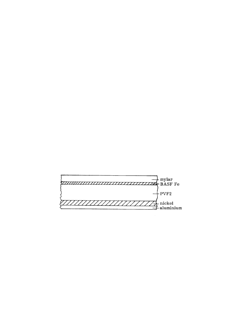
64
©
HAROLD ASPDEN, 1994
ENERGY SCIENCE REPORT NO. 2
Unfortunately, I do not have a detailed specification on this as the material I used was
part of a free sample sent to Dick Ferren of Pennwalt Corporation.
The sound velocity in PVF2 is 2.2 mm per µs.
The BASF tape and the PVF2 were then treated with a 2% solution of tetra butyl
titanate in petroleum ether to improve bonding. This process must be carried out in an arid
atmosphere and then the surfaces should be exposed to a humidity of 100% or greater at a
temperature of 40
o
C. The process is extremely tricky since, if moisture is present before the
evaporation of the petroleum ether, the titanium will not bind through the metal layer on to
the PVF2 or mylar. This can be diagnosed by the white powdery appearance of the surface.
If successful the surface will exbibit a slight iridescence.
Once the petroleum ether evaporates and the iridescence is present the exposure to
humid atmosphere takes place. This will sometimes produce a slight trace of the powdery
surface but this may be washed off in petroleum ether or toluene. DO NOT USE
ISOPROYL ALCOHOL!!!
Cyanoacrylate will not polymerise in the presence of protons, i.e. at any pH below
7 the surface of PVDF will release free protons in the presence of isopropyl alcohol and thus
prevent secure bonding. The titanate layer helps to maintain a surface pH above 7 in a
moderately dry atmosphere but can not fight the catalysis of the propyl groups in the alcohol.
Fig. 1 Layered composition of laminate formed
The greater the care taken at this stage, the more chance of success later. Every
single strip should be examined before lamination for any signs of wear on the surface or any
trace of white titanate. Failure to do this will virtually guarantee delamination the instant any
voltage is applied. This process is time consuming and the several thousand strips will take
several weeks to laminate, even working ten to twelve hours a day. But skimping the
preparation means that there is no chance of creating any percentage of intact stacks and the
entire effort will be entirely wasted. The lamination jig surfaces should be positively charged
PTFE. The layers may be added one by one for a period of time equal to one quarter of the

65
©
HAROLD ASPDEN, 1994
ENERGY SCIENCE REPORT NO. 2
anaerobic cure time of the ethyl cyanocrylate. Then a press is applied at a pressure of
between 1 and 6 tonnes whilst an ammonia atmosphere is blown past the stack to catalyse
curing. Then the process is continued. Time is the main enemy. Since each layer must be
examined and the quarter cure time is typically 30 seconds, this is a very intensely stressful
process. I managed to complete only one stack on the first day and had scrapped nearly a
thousand layers in the process. Practice improved the situation.
The PVF2 and the BASF tape were laminated together layer by layer to reach a
thickness of 0.55 mm, i.e. half λ at 2MHz. This process was repeated until a large number
of stacks were produced. Next a 5,000 volt supply was connected across each stack and
those that vaporised were discarded. A suitable breathing apparatus should be worn during
this process since the fluorine gas emitted as the PVDF breaks down is highly poisonous.
It is also corrosive and so the entire process should be carried out at a suitable location and
well away from glass, since the hydrofluoric acid will cloud the glass, making you unpopular
with your colleagues! The percentage of stacks that break down depends on the defect
density of the original PVF2. That percentage depends on whether a gel colloid or
suspension process was used during polymerisation. The use of gel tends to leave micro
bubbles of gel in the PVF2, reducing the breakdown voltage.
The surface chemistry of a poled polymer is a constant problem since the creation of
compound acetates with various metals can occur with very little encouragement. The
passing of a current through the cyanocrylate often starts a cascade catalysis which, once
started is unstoppable. This is worst with copper where even a few seconds of current will
produce a sufficient 'seed' to result in the total acetisation of the metal within a month or so.
With nickel the process is less easily turned on since a sulphate must exist before the process
starts. The initial test voiltage does not usually initiate a corrosion and so the elements may
be stored anaerobically and aridly for an indefinite period. Once the elements are subjected
to operational voltages or are even accidentally squeezed, which produces enormous voltages
in local areas, a gradual decay of metal begins. This will begin in spots surrounding any non-
polymerised cyanocrylate. Such spots exist since, even with all the precautions described,
certain free H
+
ions will be present preventing polymerisation. This is why such care MUST
be taken. The metal layers can disappear in just a few hours if the defect density in the
bonding layers exceeds 2 per cm
2
. The reduction in decay time is exponentially proportional
to defect density.
The remaining stacks were now measured for electrical conductivity and those that
showed a resistance of greater than 0.001 ohm from side to side were discarded. The
apparatus for measurement of the resistance is designed to cancel the apparatus resistance.
The electrodes of the apparatus were a pair of steel slip gauges. This is needed in the
ultrasonic device to prevent the waveform from distorting. In the thermoelectric
application this stage-by-stage testing is even more critical since it defines both the
electrical and thermal conductivity of the stack.*
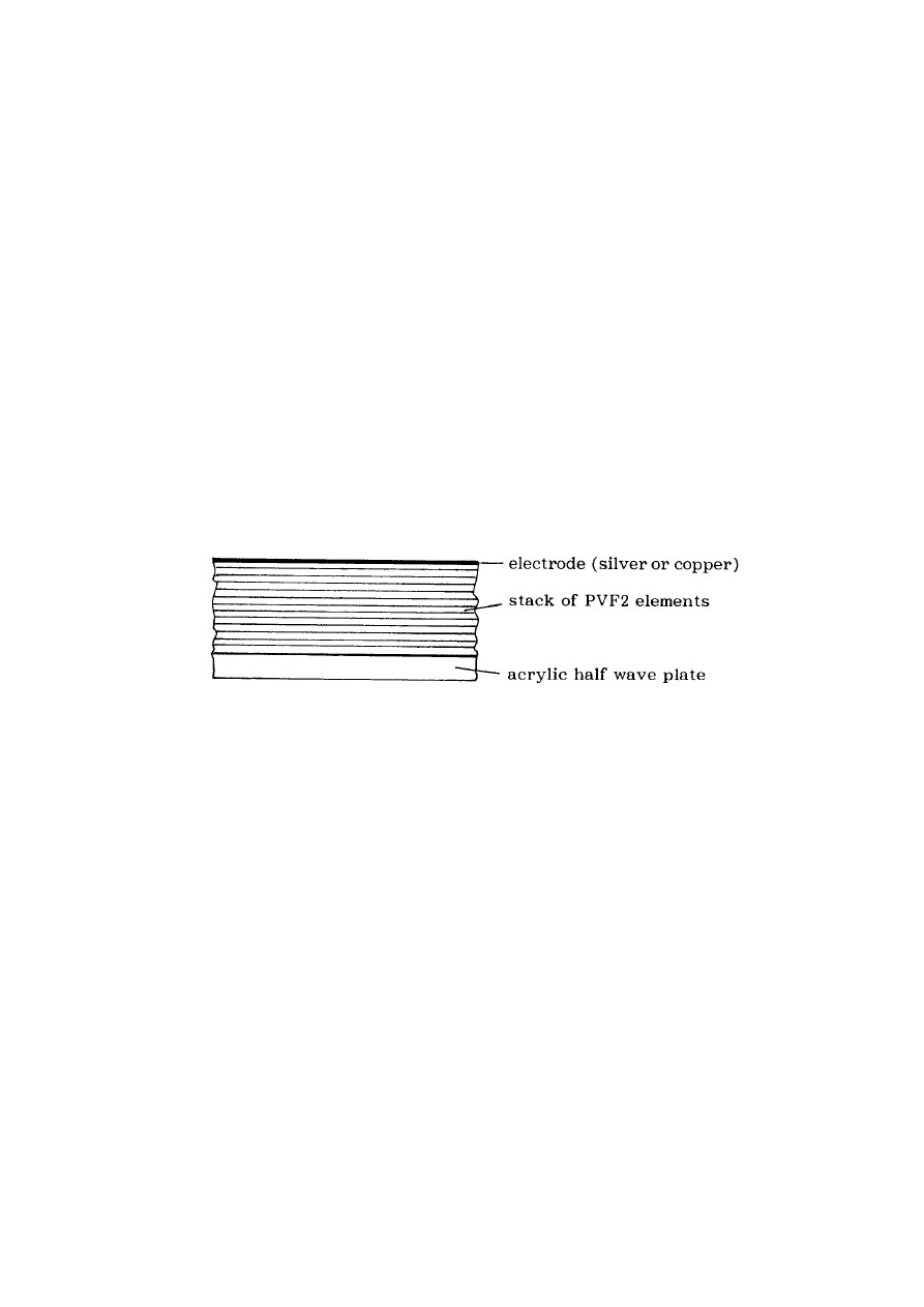
66
©
HAROLD ASPDEN, 1994
ENERGY SCIENCE REPORT NO. 2
Those elements discarded for resisitivity reasons were reground on the edges with a
fine diamond wheel in liquid nitrogen to improve flatness and were set aside for an attempt
at a slightly thinner stack. (As it happened these discards were lost and only found again at
the end of last year [1993] when they were used to construct the third thermoelectric
demonstration device.)
The original batch was divided into several sets of 50 elements.
Each element was coated with Emmerson and Cumming silver loaded epoxy and
bonded to a thin copper or silver strip, top and bottom. Silver is preferable to prevent the
production of copper acetate from the cyanoacrylate but I did not have a large quantity of this
and by this time was pretty impatient to see if the device would produce the high power
ultrasonic pulse I hoped.
Each element was then laminated to a layer of hard acrylic half λ thick as shown in
Fig. 2 below.
Fig. 2 Composition of bonded element
___________________________________________________________________ *
Emphasis here added by H. Aspden, this being the first reference to the thermoelectric
properties and much of the foregoing description having concerned the fabrication of a
structure intended to withstand mechanical oscillations at acoustic frequencies. The
thermoelectric application requires the nickel and aluminium layers to remain intact and in
mutual interface contact and does not require those metals to be as thin and fragile as they
were in the process described by Strachan. [This footnote by H. Aspden].
These elements were then assembled as shown in Fig. 3, with the ceramic driver at
one end.
Each element was then connected by its electrodes to a drive circuit. The ceramic
transducer bonded to the end of the stack was connected to be pulsed by a conventional
driver. As the wave passed
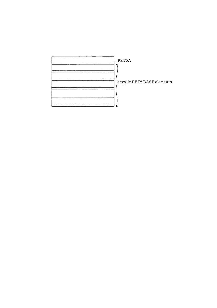
67
©
HAROLD ASPDEN, 1994
ENERGY SCIENCE REPORT NO. 2
through the stack an electromagnetic signal from the moving magnets triggered the pulses
through the stack in a cascade. By adjusting the
Fig. 3. Final stack assembly
threshold of the trigger circuit, the frequency could be tuned to match the oncoming wave.
Thus, even though the delay through the stack was inconsistent due to the variation in the
bonding thickness, the cascade of pulses could always be kept in phase with the advance of
the compression wave. A straightforward sequential delay could not do this, which was why
other attempts at 'sonic lasers' had failed to produce the expected amplification.
Everything worked fine except that as soon as the stack was moved, almost as
soon as it was touched, the drive circuit would blow. This was surprising since this was
no wimpy drive and had the capacity to deliver more than a joule per pulse. But closer
examination revealed that the circuit was not blowing in the 'ON' cycle but in the 'OFF'
cycle.
A sector of the stack was connected across an oscilloscope and the waveform in
Fig. 4 was observed when a thermal gradient was across the stack while only noise was
visible in the absence of the gradient.*
At first I naturally assumed that this pulse was a high impedance phenomenon, but
I had to wait for a couple of days to investigate since it had blown the oscilloscope.
____________________________________________________________________
* Emphasis added by H. Aspden.
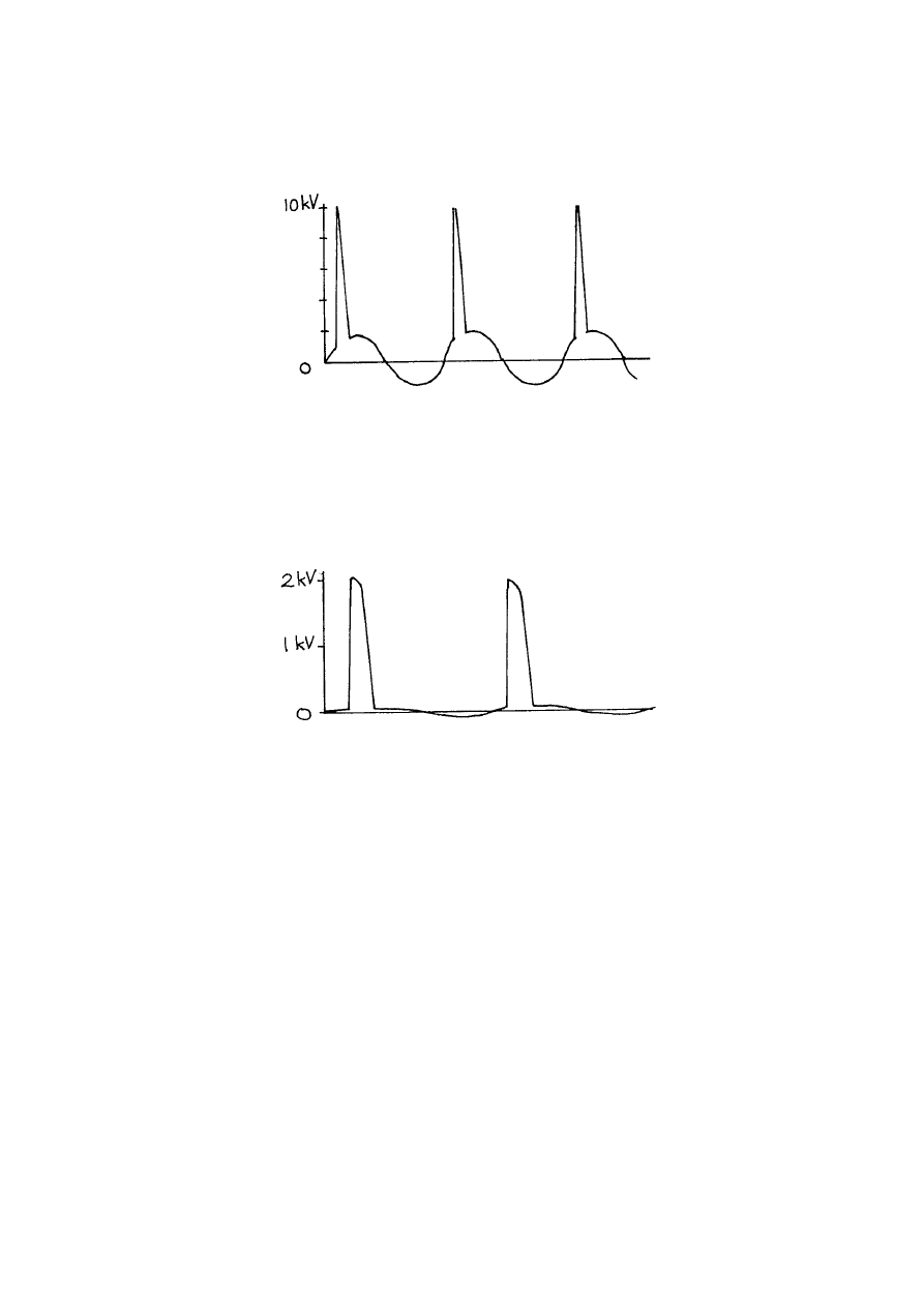
68
©
HAROLD ASPDEN, 1994
ENERGY SCIENCE REPORT NO. 2
Fig. 4. Spike voltage waveform produced by thermal gradient
A charge amplifier arrangement with a virtual dead short was now attached to the
sector of the stack and the waveform had the shape shown in Fig. 5. Note that both of these
measurements are of a sector of the stack not connected to the drive circuit.
Fig. 5. Thermally developed spike voltage with circuit protection
This was very surprising. Clearly the spikes carried a lot of current and in fact even
the impedance of the charge amplifier was too high to discharge the spike before it was
driven off. As lower and lower impedances were tried it was eventually possible to discharge
the spike in the 200 ns of its duration and get a measure of the number of joules involved.
This turned out to be broadly proportional to the temperature differential across the
stack and reached a peak at about 0.05 of a micro joule at about 70
o
C temperature
differential.
The lithotriptor circuit was redesigned to short out the stacks behind the wavefront
but even the VMOS kept blowing in the 'OFF' state now, as the voltages were just too high.
This was bitterly disappointing since the acoustic energy in the pulse from a single full
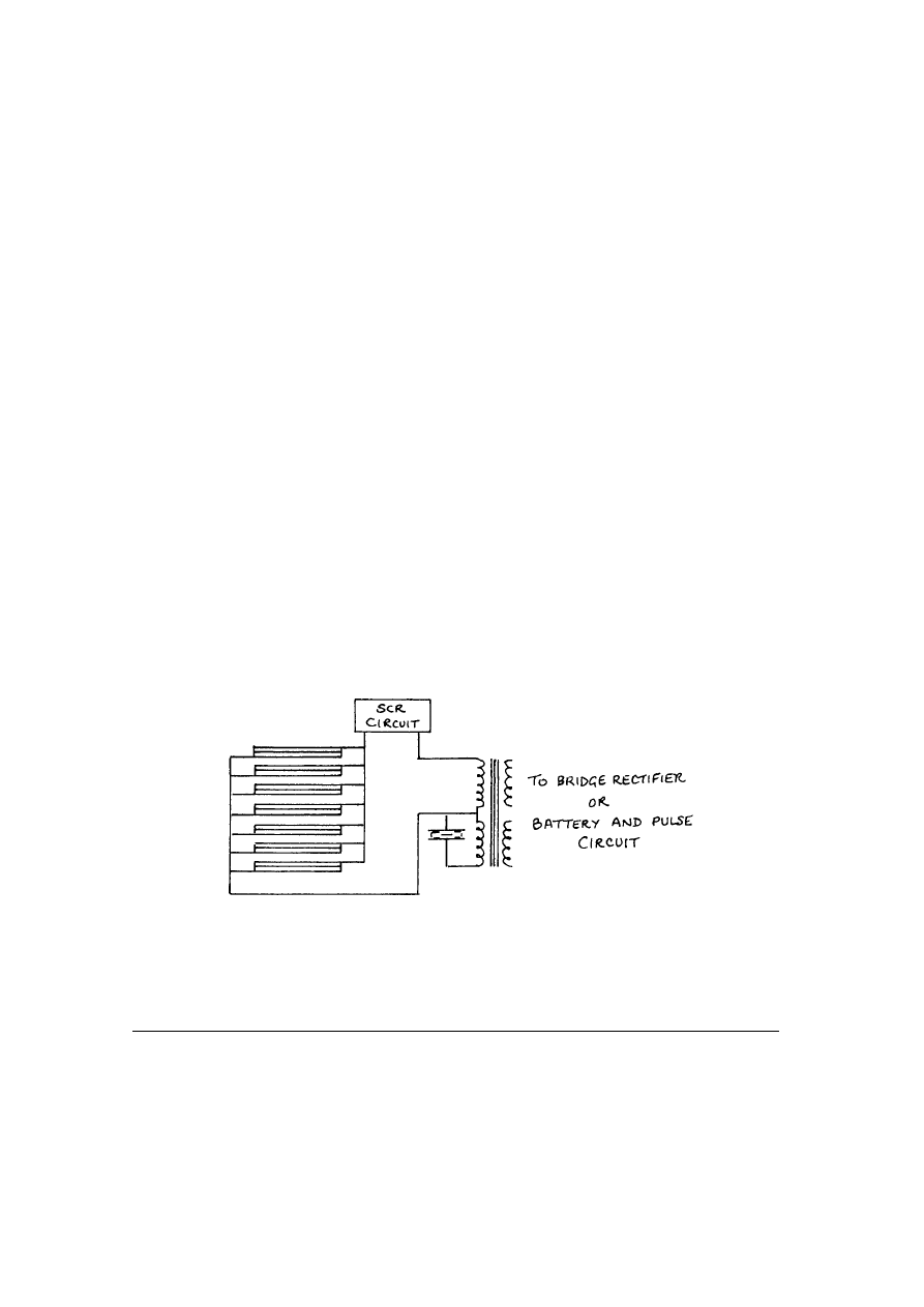
69
©
HAROLD ASPDEN, 1994
ENERGY SCIENCE REPORT NO. 2
25mm stack was truly immense and the full array would have been capable of pulverising
a 10 mm stone to dust in a few seconds without the sharp edges in the remnant rubble that
cause much trouble in laser lithotriptors. By this time, however, high power lasers were
already beginning to fall in price and it seemed as though the window of opprtunity for the
device was closing.
I had reported the thermoelectric effect to Dr. Aspden at this stage and I had
suggested that perhaps the pyroelectric and thermoelectric effects were interacting in some
way. Dr. Aspden was sceptical and proposed a number of alternatives. I built some devices
using diode arrays as disclosed in an early patent* but my experimental technique was
appalling and so I cannot rely on the measurements made on the device.
The exact number of layers in each stack in the device tested to obtain the above
signal waveforms is not known, since the acoustic thickness was all that mattered, but a fair
estimate would be about 20 - 30 layers. Thus the assembly would represent 20 series stacks
connected in parallel when connected as a finished assembly.
For the thermoelectric application I rewired the stack to produce a standing wave
rather than a travelling wave and set up the circuit with a combination tuning transformer,
thus creating a stack consisting of a combination of serial and parallel connections in a series
resonant circuit with the stack and with an omnitron SCR.
The circuit configuration is as shown in Fig. 6.
Fig. 6 Series-parallel connections of laminar stack
* This is the subject of U.S. Patent No. 5,065,085, whereas the later prototype laminar
stack thermoelectric devices became the subject of U.S. Patent No. 5,288,336.

70
©
HAROLD ASPDEN, 1994
ENERGY SCIENCE REPORT NO. 2
[Footnote by H. Aspden]
________________________________________________________________
Off voltage was now less of a problem since the actual rising edge of the spike would turn
on the CRS before the junction blew, but even so the resonant circuit meant that flyback
voltages were still dangerous in the OFF condition. Keeping the output of the transformer
coupled to low impedance prevented this from being terminal.
The amount of energy in each pulse is difficult to explain since the capacitance of the
stack as measured by a bridge was far too low to account for the energy magnitude of the
pulse. The combination of pyroelectric behaviour and thermoelectric behaviour seems to
combine with either a sudden increase in the effective capacitance or perhaps a brief
conductive phase through the PVF2. The resulting stack was connected to an input circuit
and to an output path via a transformer and then through a rectifier circuit. The rectifier
circuit should use very low voltage drop diodes to reduce voltage drop losses.
The rest of the story is well known* but a few points are worth making. The first and
third prototype devices produced a reversible effect, ie. the provision of high energy
electrical pulses to the stack resulted in the appearance of a dramatic temperature differential
across the stack. The second device, built without the magnetic interface strips, did not do
this and also was incapable of self-driving through an SCR. The electrical efficiency was
measured accurately in terms of the transfer of heat and the electrical output of the device
but the amount of breakthrough from the external drive circuit was ignored. Were the
measurements valid?** As I recall several results were surprising but were explained away
by some fancy footwork from Dr. Aspden. The third device did indeed produce a
reasonably impressive thermoelectric efficiency as a generator but detailed analysis of the
measurements of the device as a heat pump show that its performance is nowhere near as
efficient as would be expected. While this is explainable to some extent from the predicted
behaviour of the protection circuitry, the fact remains that as a heat pump the device
performs no better and perhaps worse than several commercially available heat pumps. What
if the discrepancy between the thermoelectric generator effect and the heat pump effect is the
result of a transient electrochemical effect? The chemical interaction of cyanoacrylate and
metal is already known to be charge sensitive and is very temperature sensitive. This is a
__________________________________________________________________
This is a reference to the information which has been published by articles, conferences and
patent specifications in endeavouring to promote interest in the Strachan-Aspden invention.
** Underlining by H. Aspden. This is a surprising statement. The tests in question are the
subject of Appendix IV already presented. As stated on page 42 we used a function
generator to provide an input signal to regulate electrical power delivery in pulsations at the
control frequency. The signal input of a few volts was fed through a high-valued resistor so
that minimal input current could 'break through' to feed power into the output circuit from
the function generator. It would seem therefore that Strachan here is registering his own

71
©
HAROLD ASPDEN, 1994
ENERGY SCIENCE REPORT NO. 2
personal reservations about the high operational efficiency of that now-defunct tested device.
[Footnotes by H. Aspden]
major nightmare for me. What if, in fact, all we have is an endothermic electochemical
reaction? Several gels exist that freeze when subjected to an electrical current. And a lot of
those are acetates! The electrical generation effect is even more common.
The current device is now inert but it is likely that not all elements will have decayed.
I am now dismantling the device and will attempt to recover as many elements as possible.
I would propose the best use that could be made of these is to distribute them to various
laboratories that propose to attempt to construct a device.
[End of Strachan's February 2, 1994 Communication]
*******************************************
Concluding Comment
It has become clear, and especially in the light of the above-stated position
taken by Strachan, that ongoing experimental research on the phenomenon
underlying the Strachan-Aspden invention will need to be undertaken by
Strachan's coinventor, myself, as author of this Report, in following my own
different convictions concerning base metal properties when activated
thermoelectrically using a.c. However, I can but hope that research interests
of those having the appropriate academic or corporate affiliations who come
to read this Report will see the merit in the Nernst Effect interpretation of the
tranverse a.c. action, as described in the initial commentary of this Energy
science Report No. 2, and will undertake their own investigations in pursuit
of this new technology. The outcome of my own efforts will be reported in
Energy Science Report No. 3.
Wyszukiwarka
Podobne podstrony:
Aspden POWER FROM ICE THE THERMOELECTRIC REGENERATOR (1997)
Aspden POWER FROM WATER COLD FUSION PART 1 (1994)
Aspden POWER FROM MAGNETISM THE POTTER DEBATE (1994)
Aspden POWER FROM SPACE INERTIA AND GRAVITATION (1994)
Aspden POWER FROM MAGNETISM (2004)
Aspden POWER FROM MAGNETISM OVER UNITY MOTOR DESIGN (1996)
Aspden POWER FROM SPACE THE CORREA INVENTION (1996)
Ship Power Systems and Design Part 3
Game of Thrones Iron From Ice poradnik do gry
Home Power Magazine Extract ThermoElectric Generators
Switch Mode Power Supply (Smps) Topologies (Part I) Microchip
David Runciman Political Hypocrisy, The Mask of Power, from Hobbes to Orwell and Beyond (2008)
Eurocode 4 Part 2 DDENV 1994 2 1997
Eurocode 4 Part 1,1 prEN 1994 1 1 2004
Eurocode 7 Part 1 DDENV 1997 1 1994
Eurocode 2 Part 1,6 DDENV 1992 1 6 1994
44905242 Recipes from Power Foods by the Editors of Whole Living Magazine
Eurocode 2 Part 1,4 DDENV 1992 1 4 1994
więcej podobnych podstron