
DRAFT FOR DEVELOPMENT
DD ENV
1997-1:1995
Eurocode 7:
Geotechnical design —
Part 1: General rules —
(together with United Kingdom
National Application Document)

DD ENV 1997-1:1995
This Draft for Development,
having been prepared under
the direction of the Sector
Board for Building and Civil
Engineering, was published
under the authority of the
Standards Board and comes
into effect on
15 July 1995
© BSI 03-2000
The following BSI reference
relates to the work on this
Draft for Development:
Committee reference B/526
ISBN 0 580 24511 X
Committees responsible for this Draft
for Development
The preparation of the National Application Document for use in the UK
with ENV 1997-1:1994 was entrusted to Technical Committee B/526,
Geotechnics, upon which the following bodies were represented:
Association of Consulting Engineers
Association of Geotechnical Specialists
Department of the Environment (Property and Buildings Directorate)
Department of Transport
Federation of Civil Engineering Contractors
Federation of Piling Specialists
Institution of Civil Engineers
Institution of Structural Engineers
Amendments issued since publication
Amd. No.
Date
Comments

DD ENV 1997-1:1995
© BSI 03-2000
i
Contents
Page
Committees responsible
Inside front cover
National foreword
ii
Text of National Application Document
iii
Foreword
2
Text of ENV 1997-1
7

DD ENV 1997-1:1995
ii
© BSI 03-2000
National foreword
This publication comprises the English language version of ENV 1997-1:1994
Eurocode 7: Geotechnical design — Part 1: General rules, as published by the
European Committee for Standardization (CEN) plus the National Application
Document (NAD) to be used with the ENV for design of foundations and
geotechnical structures to be constructed in the United Kingdom.
ENV 1997-1 results from a programme of work sponsored by the European
Commission to make available a common set of rules. The full range of codes
covers the basis of design and actions, the design of structures in concrete, steel,
composite construction, aluminium, timber and masonry, and geotechnics and
seismic design.
An ENV is made available for provisional application during a period of trial use
of 3 years, but does not have the status of a fully agreed European Standard (EN).
At the end of the trial period the aim is to use the experience gained to modify the
ENV so that it can be approved as an EN.
The values of some of the parameters in the ENV Eurocodes may be set by
member states so as to meet the requirements for safety in national regulations.
The values to be used in the UK are given in clause 4 of this NAD.
The NAD contains references to alternative, supporting documents, pending the
publication of relevant European Standards. These references are given
in Annex A of this NAD.
The purpose of the NAD is to provide essential information, particularly in
relation to safety, necessary for provisional application of the ENV and it
therefore constitutes an essential part of this publication in the UK. The
recommendations of the NAD take precedence in the UK over the corresponding
provisions in the ENV.
Compliance with ENV 1997-1 and the NAD does not in itself confer immunity
from legal obligations.
Users of this document are invited to comment on its technical content, ease of
use and any ambiguities or anomalies. These comments will be taken into account
when preparing the UK national response to CEN on the question of whether the
ENV can be converted to an EN.
Comments should be made in writing to BSI, 389 Chiswick High Road, London
W4 4AL, quoting this document, the reference to the relevant clause, and if
possible, a proposed revision, within 2 years of the issue of this document.
Textual errors. When implementing the English language version of
ENV 1997-1:1994 as the national prestandard, the textual errors listed below
were discovered. They have been reported to CEN in a proposal to amend the text
of the European Prestandard.
In line 1 of item 4 in 6.5.3 “(6.5)” should read “(6.2)”.
In line 3 of item 3 in 6.6 “(2.4.5)” should read “(2.4.6)”.
In line 4 of item 4 in 8.8.5 “pile” should read “anchorage”.
In equation G.2 of Annex G “a” should read “a½”.
Summary of pages
This document comprises a front cover, an inside front cover, pages i and ii,
the National Application Document title page, pages ii to x, the ENV title page,
pages 2 to 88 and a back cover.
This standard has been updated (see copyright date) and may have had
amendments incorporated. This will be indicated in the amendment table on the
inside front cover.

DD ENV 1997-1:1995
© BSI 03-2000
National Application
Document
for use in the UK with
ENV 1997-1:1994

DD ENV 1997-1:1995
ii
© BSI 03-2000
Contents of
National Application Document
Page
Introduction
iii
1
Scope
iii
2
References
iii
3
Definitions
iii
4
Values of partial factors
iii
5
Reference standards
v
6
Additional recommendations
v
Annex A (informative) References to supporting standards in Eurocode 7
vi
Annex B (normative) Additional recommendations
vi
Table 1 — Partial factors — ultimate limit states in persistent
and transient situations
iv
Table 2 — Factors to derive the ultimate characteristic
bearing resistance
iv
Table 3 — Factors to derive the ultimate design bearing resistance
iv
Table 4 — Factors to derive ultimate characteristic pile tensile
resistance from tests
iv
Table 5 — Factors to derive ultimate characteristic resistance
from anchorage tests
iv
Table A.1 — References in EC 7 to other codes and standards
vi
List of references
ix

DD ENV 1997-1:1995
© BSI 03-2000
iii
Introduction
This National Application Document has been prepared by Technical Committee B/526 to
enable ENV 1997-1 (Eurocode 7-1) to be used for the design of geotechnical structures to be constructed in
the United Kingdom. It has been developed from:
a) a textual examination of ENV 1997-1; and
b) trial calculations, including parametric calibration against relevant UK codes and standards, to
assess its ease of use and to provide numerical factors that produce designs in general conformity with
UK practice.
1 Scope
This National Application Document (NAD) provides information required to enable ENV 1997-1 to be
used for most routine designs for geotechnical structures that are to be constructed in the UK.
2 References
2.1 Normative references
This National Application Document incorporates, by dated or undated reference, provisions from other
publications. These normative references are made at the appropriate places in the text and the cited
publications are listed on the inside back cover. For dated references, only the edition cited applies: any
subsequent amendments to or revisions of the cited publication apply to this National Application
Document only when incorporated in the reference by amendment or revision. For undated references, the
latest edition of the cited publication applies, together with any amendments.
2.2 Informative references
This National Application Document refers to other publications that provide information or guidance.
Editions of these publications current at the time of issue of this standard are listed on the inside back
cover, but reference should be made to the latest editions.
3 Definitions
For the purposes of this National Application Document the following definitions apply.
NOTE ENV 1997-1 uses terminology that may not be wholly familiar to UK engineers, such as “action” and “execution”. Definitions
of these terms may be found in ENV 1991-1 and ENV 1997-1 and are reproduced here for convenience.
3.1
action
force (load) applied to the structure (direct action); or an imposed or constrained deformation (indirect
action)
NOTE For example caused by temperature changes, moisture variation or uneven settlement.
3.2
execution
activity of creating a building or civil engineering works
NOTE The term covers work on site; it may also signify the fabrication of components off site and their subsequent erection on site.
4 Values of partial factors
a) In this clause, values of partial factors currently do not differ from those used in ENV 1997-1.
NOTE In the state of development of this NAD at July 1995, no deviations from boxed values are proposed.
b) Clause 2.4.2 (14) P Table 2.1 should be replaced by Table 1 of this NAD. For accidental situations all
numerical values of partial factors for actions should be 1.0.
c) Clause 7.6.3.2 (6) P For the derivation of the ultimate characteristic bearing resistance of piles in
compression, the factors to be used should be those given in Table 2 of this NAD, which should be
substituted for Table 7.1.
d) Clause 7.6.3.2 (10) P For the derivation of the design ultimate bearing resistance of piles in
compression, the values of partial factors should be those given in Table 3 of this NAD, which should be
substituted for Table 7.2.
e) Clause 7.6.3.3 The value 1.5 should be substituted for the bracketed value [1.5].
DD ENV 1997-1:1995
iv
© BSI 03-2000
f) Clause 7.7.2.2 (2) P For the derivation from pile load tests of ultimate characteristic values of the
resistance of piles in tension, the values of partial factors to be applied to the measured ultimate tensile
resistance should be those given in Table 4 of this NAD, which should be substituted for Table 7.3.
g) Clause 7.7.2.2 (4) P The factor to derive the design value from the characteristic value should be 1.6.
h) Clause 8.8.5 (4) P For the derivation from assessment tests of the ultimate characteristic resistance
of anchorages, the values of partial factors should be those given in Table 5 of this NAD, which should
be substituted for Table 8.1.
i) Clause 8.8.5 (5) P For the derivation from characteristic resistance of the design resistance of
anchorages, the value of partial factor should be 1.25 for temporary anchorages and 1.5 for permanent
anchorages.
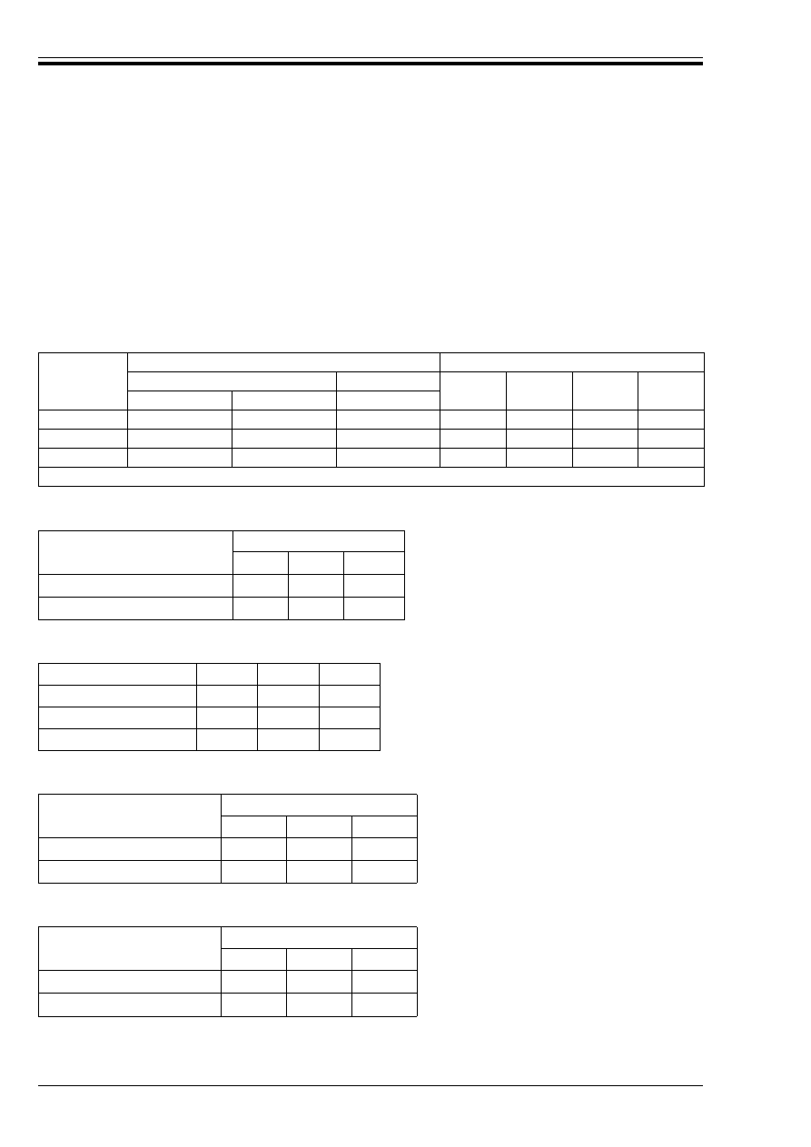
Table 1 — Partial factors — ultimate limit states in persistent and transient situations
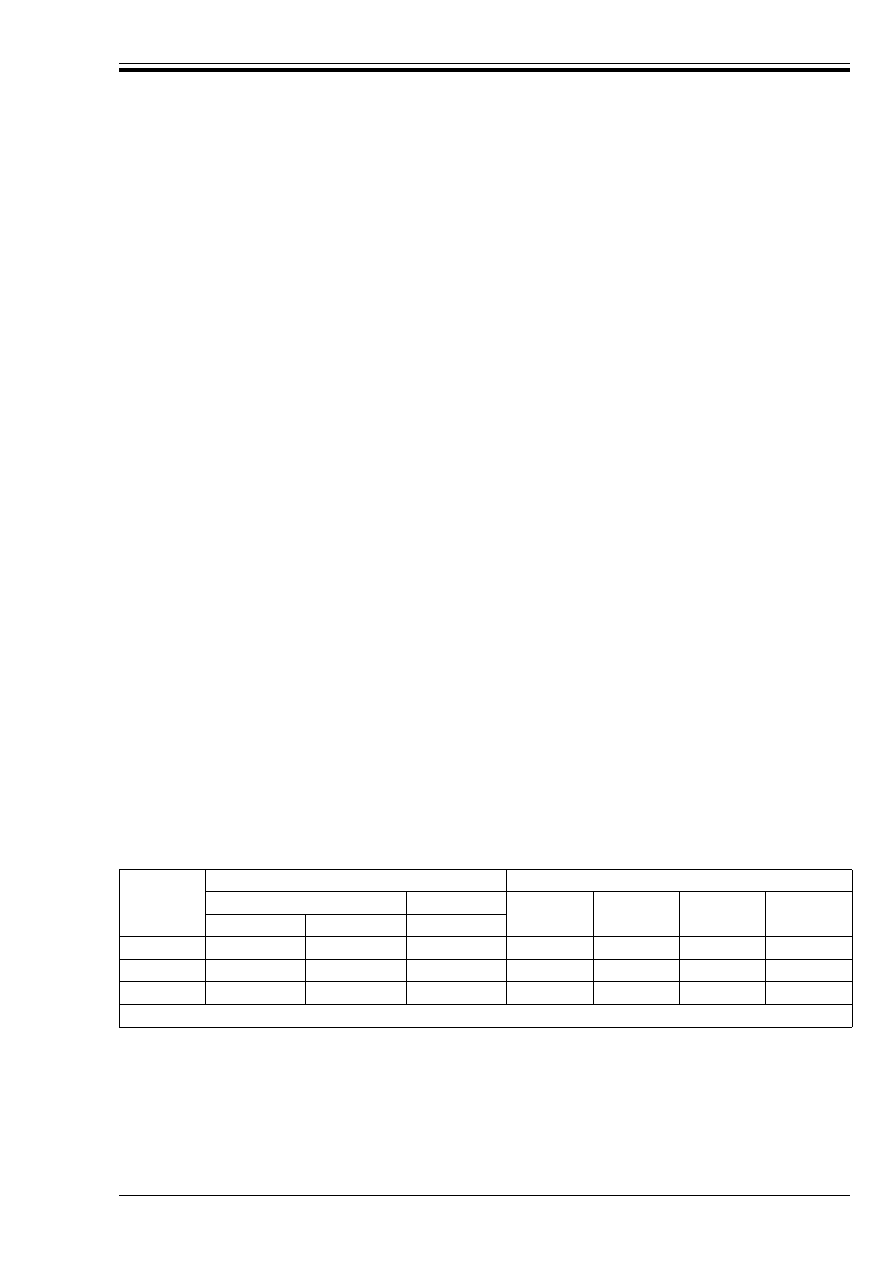
Table 2 — Factors to derive the ultimate
characteristic bearing resistance
Table 3 — Factors to derive the ultimate design
bearing resistance
Table 4 — Factors to derive characteristic ultimate
tensile pile resistance from tests
Table 5 — Factors to derive ultimate characteristic
resistance from anchorage tests
Case
Actions
Ground properties
Permanent
Variable
tan Î
c
½
c
u
q
u
a
Unfavourable
Favourable
Unfavourable
A
1.0
0.95
1.5
1.1
1.3
1.2
1.2
B
1.35
1.0
1.5
1.0
1.0
1.0
1.0
C
1.0
1.0
1.3
1.25
1.6
1.4
1.4
a
Compressive strength of soil or rock.
Number of load tests
1
2
> 2
Factor ß on mean R
cm
1.5
1.35
1.3
Factor ß on lowest R
cm
1.5
1.25
1.1
Component factors
¾
b
¾
s
¾
t
Driven piles
1.3
1.3
1.3
Bored piles
1.6
1.3
1.5
CFA piles
1.45
1.3
1.4
Number of load tests
1
2
> 2
Factor ß on mean R
m
1.5
1.35
1.3
Factor ß on lowest R
m
1.5
1.25
1.1
Number of assessment tests
1
2
> 2
Factor ß on mean R
am
1.5
1.35
1.3
Factor ß on lowest R
am
1.5
1.25
1.1

DD ENV 1997-1:1995
© BSI 03-2000
v
5 Reference standards
ENV 1997-1 does not call up supporting standards since none yet exist (see Annex A).
6 Additional recommendations
Annex B lists points that should be noted when designing to ENV 1997-1.

DD ENV 1997-1:1995
vi
© BSI 03-2000
Annex A (informative)
References to supporting standards in Eurocode 7
Table A.1 provides guidance on British Standards which support clause references in EC7 on standards for
site investigation and laboratory and field testing.
Table A.1 — References in EC 7 to other codes and standards
Annex B (normative)
Additional recommendations
B.1 General
For the geotechnical design of trunk roads and motorways within the UK, reference should be made to the
following documents of the Department of Transport, the Scottish Office Industry Department, the Welsh
Office: Y Swyddfa Gymreig and the Department of the Environment for Northern Ireland:
a) Design Manual for Roads and Bridges [1];
b) Manual for Contract Documents for Highway Works, Volumes 1 and 2 [2].
B.2 Guidance on EC7
a) Clause 2.4.2
In 2.4.2 (12)P Case B, care is required particularly in the selection of the partial factor ¾
F
when the
design of structural elements is critical. Whether earth pressures acting on the structure are
considered to be favourable or unfavourable will substantially affect the outcome (for example, in the
design of a cantilever retaining structure both the active and passive pressure distributions will
usually be unfavourable to the design of the structural section). The application rules in 2.4.2 (17) are
particularly important; the same value of ¾
F
(1.35 or 1.0) is applied to all earth and water pressures,
depending on whether the combined effect of them all is favourable or unfavourable.
The bending moments and shear forces derived from factored earth pressures should be regarded as
design values when using EC2 or other of the structural Eurocodes for the structural calculations.
If the application of ¾
F
= 1.35 leads to a physically unreasonable situation, then the factor (1.35) should
be treated as a model factor and applied to the action effects (e.g. resultant bending moment and shear
force) which are then treated as design values in EC2 or other of the structural Eurocodes.
b) Clause 5
Reference should be made to BS 6031, BS 8006
1)
and the forthcoming CEN documents from
CEN/TC 288/WG6 Execution of special geotechnical works — Grouting and CEN/TC 288/WG7
Execution of special geotechnical works — Jet grouting.
c) Clause 6
Reference should be made to BS 8004.
d) Clause 7
Reference should be made to BS 8004, BS 5573 and to the forthcoming CEN documents from
CEN/TC288/WG3 Execution of special geotechnical works — Bored piles, CEN/TC 288/WG4 Execution
of special geotechnical works — Sheet pile walls, CEN/TC 288/WG5 Execution of special geotechnical
works — Displacement piling.
Reference
location in EC7
Reference
UK equivalent document
no.
3.1 (3)P
“internationally recognized standards and recommendations”
BS 5930
BS 1377-1 to BS 1377-9
3.2.3 (6)P
“standardized procedures”
BS 5930
BS 1377-1 to BS 1377-9
3.3.4
3.3.5
“standard laboratory procedures”
BS 1377-1 to BS 1377-9
1)
In preparation.

DD ENV 1997-1:1995
© BSI 03-2000
vii
e) Clause 7.6.3.3
The adhesion factor a provides a correlation between the results of static load tests and ground test
results. If the values adopted for a and c
u
are such that the resulting value of shaft adhesion a · c
u
represents the mean of the test results, then the shaft resistance will be given by:
q
sik
= a · c
u
/1.5
then
R
sd
= R
sk
/¾
s
= ×q
sik
· A
si
/¾
s
= ×a · c
u
· A
si
/(1.5 · ¾
s
).
With
¾
s
= 1.3, the factor on a · c
u
· A
si
becomes 1.95.
f) Clause 8
Reference should be made to BS 8002, BS 8006 and to the forthcoming document from
CEN/TC288/WG2 Execution of special geotechnical works — Ground anchors.
g) Clause 9
Reference should be made to BS 6031.

viii
blank

DD ENV 1997-1:1995
© BSI 03-2000
ix
List of references
(see clause 2)
Normative references
BSI publications
BRITISH STANDARDS INSTITUTION, London
BS 5573:1978, Code of practice for safety precautions in the construction of large diameter boreholes for
piling and other purposes.
BS 6031:1981, Code of practice for earthworks.
BS 8002:1994, Code of practice for earth retaining structures.
BS 8004:1986, Code of practice for foundations.
BS 8006, Code of practice for strengthened/reinforced soils and other fills
2)
.
Other references
[1] Design Manual for Roads and Bridges
3)
.
[2] Manual for Contract Documents for Highway Works, Vols 1 and 2
3)
.
Informative references
BSI publications
BRITISH STANDARDS INSTITUTION, London
BS 1377, Methods of test for soils for civil engineering purposes.
BS 1377-1:1990, General requirements and sample preparation.
BS 1377-2:1990, Classification tests.
BS 1377-3:1990, Chemical and electro-chemical tests.
BS 1377-4:1990, Compaction-related tests.
BS 1377-5:1990, Compressibility, permeability and durability tests.
BS 1377-6:1990, Consolidation and permeability tests in hydraulic cells and with pore pressure
measurement.
BS 1377-7:1990, Shear strength tests (total stress).
BS 1377-8:1990, Shear strength tests (effective stress).
BS 1377-9:1990, In-situ tests.
BS 5930:1981, Code of practice for site investigations.
CEN publication
EUROPEAN COMMITTEE FOR STANDARDIZATION (CEN), Brussels
ENV 1991-1:1994, Eurocode 1 — Basis of design and actions on structures — Part 1: Basis of design.
2)
In preparation.
3)
Published by and available from HMSO.

x
blank

EUROPEAN PRESTANDARD
PRÉNORME EUROPÉENNE
EUROPÄISCHE VORNORM
ENV 1997-1
October 1994
ICS 91/060.00;91.120.20
Descriptors: Soils, computation, buildings codes, rules of calculation
English version
Eurocode 7: Geotechnical design —
Part 1: General rules
Eurocode 7: Calcul geotechnique —
Partie 1: Règles générales
Eurocode 7: Entwurf, Berechnung und
Bemessung in der Geotechnik —
Teil 1: Allgemeine Regeln
This European Standard (ENV) was approved by CEN on 1993-05-25 as a
prospective standard for provisional application. The period of validity of this
ENV is limited initially to three years. After two years the members of CEN
will be requested to submit their comments, particularly on the question
whether the ENV can be converted into a European Standard.
CEN members are required to announce the existance of this ENV in the same
way as for an EN and to make the ENV available promptly at national level in
an appropriate form. It is permissible to keep conflicting national standards in
force (in parallel to the ENV) until the final decision about the possible
conversion of the ENV into an EN is reached.
CEN members are the national standards bodies of Austria, Belgium,
Denmark, Finland, France, Germany, Greece, Iceland, Ireland, Italy,
Luxembourg, Netherlands, Norway, Portugal, Spain, Sweden, Switzerland and
United Kingdom.
CEN
European Committee for Standardization
Comité Européen de Normalisation
Europäisches Komitee für Normung
Central Secretariat: rue de Stassart 36, B-1050 Brussels
© 1994 Copyright reserved to CEN members
Ref. No. ENV 1997-1:1994 E

ENV 1997-1:1994
© BSI 03-2000
2
Foreword
1 Objectives of the Eurocodes
(1) The structural Eurocodes comprise a group of
standards for the structural and geotechnical design
of buildings and civil engineering works.
(2) They are intended to serve as reference
documents for the following purposes:
a) As a means to prove compliance of building and
civil engineering works with the essential
requirements of the Construction Products
Directive (CPD)
b) As a framework for drawing up harmonised
technical specifications for construction products.
(3) They cover execution and control only to the
extent that is necessary to indicate the quality of the
construction products, and the standard of the
workmanship, needed to comply with the
assumptions of the design rules.
(4) Until the necessary set of harmonised technical
specifications for products and for methods of
testing their performance is available, some of the
Structural Eurocodes cover some of these aspects in
informative annexes.
2 Background to the Eurocode
programme
(1) The Commission of the European Communities
(CEC) initiated the work of establishing a set of
harmonised technical rules for the design of
building and civil engineering works which would
initially serve as an alternative to the different rules
in force in the various Member States and would
ultimately replace them. These technical rules
became known as the “Structural Eurocodes”.
(2) In 1990, after consulting their respective
Member States, the CEC transferred work of
further development, issue and updates of the
Structural Eurocodes to CEN and the EFTA
Secretariat agreed to support the CEN work.
(3) CEN Technical Committee CEN/TC 250 is
responsible for all Structural Eurocodes.
3 Eurocode programme
(1) Work is in hand on the following Structural
Eurocodes, each generally consisting of a number of
parts:
EN 1991, Eurocode 1: Basis of design and actions
on structures.
EN 1992, Eurocode 2: Design of concrete
structures.
EN 1993, Eurocode 3: Design of steel structures.
EN 1994, Eurocode 4: Design of composite steel
and concrete structures.
EN 1995, Eurocode 5: Design of timber
structures.
EN 1996, Eurocode 6: Design of masonry
structures.
EN 1997, Eurocode 7: Geotechnical design.
EN 1998, Eurocode 8: Design of structures for
earthquake resistance.
EN 1999, Eurocode 9: Design of aluminium alloy
structures.
(2) Separate sub-committees have been formed by
CEN/TC 250 for the various Eurocodes listed above.
(3) This part of the Structural Eurocode for
Geotechnical design which had been finalised and
approved for publication under the direction of CEC,
is being issued by CEN as a European Prestandard
(ENV) with an initial life of three years.
(4) This Prestandard is intended for experimental
practical application in the design of the building
and civil engineering works covered by the scope as
given in 1.1.2 and for the submission of comments.
(5) After approximately two years CEN members
will be invited to submit formal comments to be
taken into account in determining future action.
(6) Meanwhile, feedback and comments on this
Prestandard should be sent to the Secretariat of
sub-committee CEN/TC250/SC7 at the following
address:
NNI
P.O.Box 5059
NL-2600 GB Delft
The Netherlands
or to a national standards organisation.

ENV 1997-1:1994
© BSI 03-2000
3
4 National application documents
(1) In view of the responsibilities of authorities in
member countries for the safety, health and other
matters covered by the essential requirements of
the CPD, certain safety elements in this ENV have
been assigned indicative values which are identified
by [ ]. The authorities in each member country are
expected to assign definitive values to these safety
elements.
(2) Many of the supporting standards, including
those giving values for actions to be taken into
account and measures required for fire protection,
will not be available by the time this Prestandard is
issued. It is therefore anticipated that a National
Application Document giving definitive values for
safety elements, referencing compatible supporting
standards and giving national guidance on the
application of this Prestandard will be issued by
each Member State or its Standard Organisation.
This Prestandard should be used in conjunction
with the National Application Document valid in
the country where the building and civil engineering
works is to be constructed.
It is intended that this Prestandard is used in
conjunction with the NAD valid in the country
where the building or civil engineering works are
located.
5 Matters specific to this prestandard
(1) The scope of eurocode 7 is defined in 1.1.1 and
the scope of this Part of eurocode 7 is defined
in 1.1.2. Additional Parts of Eurocode 7 which are
planned are indicated in 1.1.3; these will cover
additional technologies or applications, and will
complement and supplement this Part.
(2) In using this Prestandard in practice, particular
regard should be paid to the underlying
assumptions and conditions given in 1.3.
(3) The nine chapters of this Prestandard are
complemented by seven annexes which have
informative status.

ENV 1997-1:1994
4
© BSI 03-2000
Contents
Page
Foreword
2
Section 1. General
1.1
Scope
7
1.1.1 Scope of Eurocode 7
7
1.1.2 Scope of Part 1 of Eurocode 7
7
1.1.3 Further Parts of Eurocode 7
7
1.2
References
7
1.3
Distinction between Principles
and Application Rules
8
1.4
Assumptions
8
1.5
Definitions
8
1.5.1 Terms common to all Eurocodes
8
1.5.2 Special terms used in Eurocode 7
8
1.6
S.I. units
8
1.7
Symbols common to all Eurocodes
9
1.8
Symbols used in Eurocode 7
9
1.8.1 Latin upper case letters
9
1.8.2 Latin lower case letters
9
1.8.3 Greek lower case letters
9
1.8.4 Subscripts
10
Section 2. Basis of geotechnical design
2.1
Design requirements
11
2.2
Design situations
12
2.3
Durability
13
2.4
Geotechnical design by calculation
13
2.4.1 Introduction
13
2.4.2 Actions in geotechnical design
14
2.4.3 Ground properties
16
2.4.4 Design strength of structural materials 17
2.4.5 Geometrical data
18
2.4.6 Limiting values for movements
18
2.5
Design by prescriptive measures
19
2.6
Load tests and tests on
experimental models
19
2.7
The observational method
19
2.8
The Geotechnical Design Report
19
Section 3. Geotechnical data
3.1
General
21
3.2
Geotechnical investigations
21
3.2.1 Introduction
21
3.2.2 Preliminary investigations
21
3.2.3 Design investigations
22
3.3
Evaluation of geotechnical parameters
23
3.3.1 General
23
Page
3.3.2 Characterization of soil and rock type
24
3.3.3 Unit weight
24
3.3.4 Relative density
24
3.3.5 Degree of compaction
25
3.3.6 Undrained shear strength of
cohesive soils
25
3.3.7 Effective shear strength parameters
for soils
25
3.3.8 Soil stiffness
25
3.3.9 Quality and properties of rocks
and rock masses
26
3.3.10 Permeability and consolidation
parameters
27
3.3.11 Cone parameters
27
3.3.12 Blow count from standard penetration
tests and dynamic probing
27
3.3.13 Pressuremeter parameters
28
3.3.14 Dilatometer parameters
28
3.3.15 Compactibility
28
3.4
Ground Investigation Report
28
3.4.1 Presentation of geotechnical information 28
3.4.2 Evaluation of geotechnical information
29
Section 4. Supervision of construction,
monitoring and maintenance
4.1
General requirements
30
4.2
Supervision
30
4.2.1 Plan of supervision
30
4.2.2 Inspection and control
30
4.2.3 Assessment of the design
31
4.3
Checking ground conditions
31
4.3.1 Soil and rock
31
4.3.2 Groundwater
31
4.4
Checking construction
32
4.5
Monitoring
32
4.6
Maintenance
33
Section 5. Fill, dewatering, ground
improvement and reinforcement
5.1
General
34
5.2
Fundamental requirements
34
5.3
Fill construction
34
5.3.1 Principles
34
5.3.2 Selection of fill material
34
5.3.3 Selection of fill placement and
compaction procedure
35
5.3.4 Checking the fill
35
5.4
Dewatering
36

ENV 1997-1:1994
© BSI 03-2000
5
Page
5.5
Ground improvement and
reinforcement
37
Section 6. Spread foundations
6.1
General
38
6.2
Limit states
38
6.3
Actions and design situations
38
6.4
Design and construction considerations 38
6.5
Ultimate limit state design
39
6.5.1 Overall stability
39
6.5.2 Bearing resistance failure
39
6.5.3 Failure by sliding
39
6.5.4 Loads with large eccentricities
40
6.5.5 Structural failure due to
foundation movement
41
6.6
Serviceability limit state design
41
6.6.1 Settlement
41
6.6.2 Vibration analysis
42
6.7
Foundations on rock: Additional
design considerations
42
6.8
Structural design
42
Section 7. Pile foundations
7.1
General
44
7.2
Limit states
44
7.3
Actions and design situations
44
7.3.1 General
44
7.3.2 Actions due to ground displacement
44
7.4
Design methods and design
considerations
45
7.4.1 Design methods
45
7.4.2 Design considerations
46
7.5
Pile load tests
46
7.5.1 General
46
7.5.2 Static load tests
47
7.5.3 Dynamic load tests
48
7.5.4 Load test report
48
7.6
Piles in compression
48
7.6.1 Limit state design
48
7.6.2 Overall stability
48
7.6.3 Bearing resistance
49
7.6.4 Settlement of pile foundations
52
7.7
Piles in tension
52
7.7.1 General
52
7.7.2 Ultimate tensile resistance
52
7.7.3 Vertical displacement
54
7.8
Transversely loaded piles
54
7.8.1 General
54
Page
7.8.2 Ultimate transverse load resistance
55
7.8.3 Transverse displacement
55
7.9
Structural design of piles
56
7.10
Supervision of construction
56
Section 8. Retaining structures
8.1
General
58
8.2
Limit states
58
8.3
Actions, geometrical data and
design situations
59
8.3.1 Actions
59
8.3.2 Geometrical data
60
8.3.3 Design situations
60
8.4
Design and construction considerations 60
8.5
Determination of earth and water
pressures
61
8.5.1 Design earth pressures
61
8.5.2 At rest values of earth pressure
62
8.5.3 Limit values of earth pressure
62
8.5.4 Intermediate values of earth pressure
63
8.5.5 Compaction effects
63
8.5.6 Water pressures
63
8.6
Ultimate limit state design
63
8.6.1 General
63
8.6.2 Overall stability
64
8.6.3 Foundation failure of gravity walls
64
8.6.4 Rotational failure of embedded walls
65
8.6.5 Vertical failure of embedded walls
65
8.6.6 Structural failure
66
8.6.7 Failure by pull-out of anchors
67
8.7
Serviceability limit state
67
8.7.1 General
67
8.7.2 Displacements
67
8.7.3 Vibrations
68
8.7.4 Structural serviceability limit states
68
8.8
Anchorages
68
8.8.1 Scope
68
8.8.2 Anchorage design
68
8.8.3 Construction considerations
69
8.8.4 Anchorage testing
69
8.8.5 Assessment tests
69
8.8.6 Acceptance tests
70
8.8.7 Supervision of construction and
monitoring
70
Section 9. Embankments and slopes
9.1
General
72

ENV 1997-1:1994
6
© BSI 03-2000
Page
9.2
Limit states
72
9.3
Actions and design situations
72
9.4
Design and construction considerations 72
9.5
Ultimate limit state design
73
9.5.1 Loss of overall stability
73
9.5.2 Deformations
73
9.5.3 Superficial erosion, internal erosion
and hydraulic uplift
74
9.5.4 Rockslides
74
9.5.5 Rockfalls
74
9.5.6 Creep
74
9.6
Serviceability limit state design
74
9.7
Monitoring
75
Annex A (informative) Check list for
construction supervision and performance
monitoring
76
A.1
Construction supervision
76
A.1.1 General items to be checked
76
A.1.2 Water flow and pore pressures
76
A.2
Performance monitoring
76
Annex B (informative) A sample analytical
method for bearing resistance calculation
77
B.1
General
77
B.2
Undrained conditions
77
B.3
Drained conditions
77
Annex C (informative) A Sample
semi-empirical method for bearing
resistance estimation
78
Annex D (informative) Sample methods
for settlement evaluation
78
D.1
Stress-strain method
78
D.2
Adjusted elasticity method
79
D.3
Settlements without drainage
79
D.4
Settlements caused by consolidation
79
D.5
Time-settlement behaviour
79
Annex E (informative) A sample method for
deriving presumed bearing resistance for
spread foundations on rock
80
Annex F (informative) A sample calculation
model for the tensile resistance of individual
or grouped piles
82
Annex G (informative) Sample procedures
to determine limit values of earth pressure
83
Figure 7.1 — Uplift failure of a group of
piles in tension
53
Figure 8.1 — Examples of limit modes for
overall stability of retaining structures
64
Figure 8.2 — Examples of limit modes
for foundation failures of gravity walls
64
Page
Figure 8.3 — Examples of limit modes
for rotational failures of embedded walls
65
Figure 8.4 — An example of a limit mode
for vertical failure of embedded walls
65
Figure 8.5 — Examples of limit modes
for structural failure of retaining structures
66
Figure 8.6 — Examples of limit modes for
failure by pull-out of anchors
67
Figure E.1 — Presumed bearing resistance
for square pad foundations bearing on rock
(for settlements not exceeding 0,5 % of
foundation width). For types of rock in
each of four groups, see Table E.1.
Presumed bearing resistance in hatched
areas to be assessed after inspection
and/or making tests on rock
81
Figure F.1 — Model to check tensile
resistance of individual or grouped piles
82
Figure G.1 — Coefficients of active earth
pressure (horizontal component) for
horizontal retained surface
84
Figure G.2 — Coefficients of passive
earth pressure (horizontal component)
for horizontal retained surface
84
Figure G.3 — Coefficients of active
earth pressure (horizontal component)
for general case on inclined backfill
with wall friction
85
Figure G.4 — Coefficients of passive earth
pressure (horizontal component) for general
case of inclined backfill with wall friction
86
Figure G.5 — Definitions concerning
surface load, geometry of slip line etc
87
Table 2.1 — Partial factors — ultimate
limit states in persistent and
transient situations
15
Table 7.1 — Factors ß to derive R
ck
50
Table 7.2 — Values of ¾
b
, ¾
s
, and ¾
t
50
Table 7.3 — Factors to derive R
tk
54
Table 8.1 — Conversion factors ß to
derive R
sk
70
Table E.1 — Grouping of weak and
broken rocks
80
Table E.2 — Classification and
presumed bearing resistance
for high porosity chalk
80

ENV 1997-1:1994
© BSI 03-2000
7
Section 1. General
1.1 Scope
1.1.1 Scope of Eurocode 7
(1)P This prestandard applies to the geotechnical aspects of the design of buildings and civil engineering
works. It is subdivided into various separate parts. See 1.1.2 and 1.1.3.
(2)P This prestandard is concerned with the requirements for strength, stability, serviceability and
durability of the structures. Other requirements, e.g. concerning thermal or sound insulation, are not
considered.
(3)P This prestandard shall be used in conjunction with ENV 1991-1 “Basis of Design” of Eurocode 1 “Basis
of Design and Actions on Structures” which establishes the principles and requirements for safety and
serviceability, describes the basis for design and verification and gives guidelines for related aspects of
structural reliability.
(4)P This prestandard gives the rules to calculate actions originating from the ground such as earth
pressures. Numerical values of actions on buildings and civil engineering works to be taken into account
in the design are provided in ENV 1991 Eurocode 1 “Basis of Design and Actions on Structures” applicable
to the various types of construction.
(5)P In this prestandard execution is covered to the extent that is necessary to indicate the quality of the
construction materials and products which should be used and the standard of workmanship on site needed
to comply with the assumptions of the design rules. Generally, the rules related to execution and
workmanship are to be considered as minimum requirements which may have to be further developed for
particular types of buildings or civil engineering works and methods of construction.
(6)P This prestandard does not cover the special requirements of seismic design. Eurocode 8,
“Designprovisions for earthquake resistance of structures” provides additional rules for seismic design
which complete or adapt the rules of this prestandard.
1.1.2 Scope of ENV 1997-1
(1)P This prestandard gives a general basis for the geotechnical aspects of the design of buildings and civil
engineering works.
(2)P The following subjects are dealt with in ENV 1997-1 Eurocode 7: “Geotechnical design”.
— Section 1: General;
— Section 2: Basis of Geotechnical Design;
— Section 3: Geotechnical Data;
— Section 4: Supervision of Construction, Monitoring and Maintenance;
— Section 5: Fill, Dewatering, Ground Improvement and Reinforcement;
— Section 6: Spread Foundations;
— Section 7: Pile Foundations;
— Section 8: Retaining Structures;
— Section 9: Embankments and Slopes.
1.1.3 Further Parts of Eurocode 7
(1)P This prestandard will be supplemented by further Parts which will complete or adapt it for particular
aspects of special types of buildings and civil engineering works, special methods of construction and
certain other aspects of design which are of general practical importance.
1.2 References
This European Prestandard incorporates by dated or undated reference, provisions from other standards.
These normative references are cited at the appropriate places in the text and the publications are listed
hereafter. For dated references, subsequent amendments to or revisions of any of these publications apply
to this Prestandard only when incorporated in it by amendment or revision.
ISO 1000:1981, SI-units and Recommendations for the use of their multiples and of certain other units.
ISO 3898:1987, Bases for design of structures. Notations. General symbols.

ENV 1997-1:1994
8
© BSI 03-2000
1.3 Distinction between, Principles and Application Rules
(1)P Depending on the character of the individual clauses, distinction is made in this prestandard between
Principles and Application Rules.
(2)P The Principles comprise:
— general statements and definitions for which there is no alternative, as well as;
— requirements and analytical models for which no alternative is permitted unless specifically stated.
(3)P The Principles are preceded by the letter P.
(4)P The Application Rules are examples of generally recognized rules which follow the Principles and
satisfy their requirements.
(5)P It is permissible to use alternative rules different from the Application Rules given in this Eurocode,
provided it is shown that the alternative rules accord with the relevant Principles.
1.4 Assumptions
(1)P The following assumptions apply:
— data required for design are collected, recorded and interpreted;
— structures are designed by appropriately qualified and experienced personnel;
— adequate continuity and communication exist between the personnel involved in data- collection,
design and construction;
— adequate supervision and quality control is provided in factories, in plants, and on site;
— execution is carried out according to the relevant standards and specifications by personnel having
the appropriate skill and experience;
— construction materials and products are used as specified in this Eurocode or in the relevant material
or product specifications;
— the structure will be adequately maintained;
— the structure will be used in accordance with the purpose defined for the design.
1.5 Definitions
1.5.1 Terms common to all Eurocodes
(1)P The terms used in common for all Eurocodes are defined in ENV 1991-1 Basis of design.
1.5.2 Special terms used in ENV 1997-1
(1)P The following terms are used in ENV 1997-1 with the following meanings:
— comparable experience: documented or other clearly established information related to the ground
being considered in design, involving the same types of soil and rock and for which similar geotechnical
behaviour is expected, and involving similar structures. Information gained locally is considered to be
particularly relevant;
— ground: soil, rock and fill existing in place prior to the execution of the construction works;
— structure: as defined in ENV 1991-1 “Basis of design”, including fill placed during execution of the
construction works;
1.6 S.I. units
(1)P S.I. units shall be used in accordance with ISO 1000.
(2) For geotechnical calculations, the following units are recommended:
— forces
kN, MN
— moments
kNm
— mass density
kg/m
3
, Mg/m
3
, (t/m
3
)
— unit weight
kN/m
3
— stresses, pressures and strengths
kN/m
2
(kPa)
— stiffness
MN/m
2
(MPa)

ENV 1997-1:1994
© BSI 03-2000
9
1.7 Symbols common to all Eurocodes
(1)P The symbols used in common for all Eurocodes are defined in ENV 1991-1 “Basis of design”.
1.8 Symbols used in Eurocode 7
(1)P The symbols commonly used in ENV 1997-1 are defined in the following sections. Other symbols are
defined where they are used locally in the text. The notation of the symbols used is based on ISO 3898:1987.
1.8.1 Latin upper case letters
1.8.2 Latin lower case letters
1.8.3 Greek lower case letters
— coefficient of permeability
m/s, (m/year)
— coefficient of consolidation
m
2
/s, (m
2
/year)
B
width
D
diameter
F
axial or transverse load on pile
H
horizontal action or force
K
earth pressure coefficient
N
bearing resistance factor
R
vertical resistance (in units of force) of a foundation element
V
vertical action or force
a
adhesion
c½
cohesion intercept in terms of effective stress
c
u
undrained shear strength
i
hydraulic gradient
k
permeability
q
overburden or surcharge pressure
s
settlement
u
pore water pressure
*
unit weight
$
angle of shearing resistance between ground and structure
B
total normal stress
Ö
½
effective normal stress
Ù
shear stress
Ì
angle of shearing resistance
Ì
½
angle of shearing resistance in terms of effective stress

ENV 1997-1:1994
10
© BSI 03-2000
1.8.4 Subscripts
a
active earth pressure
a
anchor
b
base of pile
c
compression
d
design value
k
characteristic value
p
passive earth pressure
s
shaft of pile
t
tensile
t
total
tr
transverse
w
water
o
at rest or initial condition

ENV 1997-1:1994
© BSI 03-2000
11
Section 2. Basis of geotechnical design
2.1 Design requirements
(1)P A structure shall be designed in compliance with the general design principles given in ENV 1991-1
Eurocode 1 “Basis of Design”.
(2)P In order to establish minimum requirements for the extent and quality of geotechnical investigations,
calculations and construction control checks, the complexity of each geotechnical design shall be identified
together with the risks to property and life. In particular, a distinction shall be made between:
— light and simple structures and small earthworks for which it is possible to ensure that the
fundamental requirements will be satisfied on the basis of experience and qualitative geotechnical
investigations, with negligible risk for property and life;
— other geotechnical structures.
(3) For projects of low geotechnical complexity and risk, such as defined above, simplified design procedures
are acceptable.
(4)P The following factors shall be taken into consideration when determining the geotechnical design
requirements:
— nature and size of the structure and its elements, including any special requirements;
— conditions with regard to its surroundings (neighbouring structures, traffic, utilities, vegetation,
hazardous chemicals, etc.);
— ground conditions;
— groundwater situation;
— regional seismicity;
— influence of the environment (hydrology, surface water, subsidence, seasonal changes of moisture).
(5) To establish geotechnical design requirements three Geotechnical Categories, 1, 2 and 3, may be
introduced.
A preliminary classification of a structure according to geotechnical category should normally be performed
prior to the geotechnical investigations. This category may later be changed. The category should be
checked and eventually changed at each stage of the design and construction process.
The various design aspects of a project may require treatment in different geotechnical categories. It is not
necessary to treat the whole of the project according to the highest of these categories.
The procedures of higher categories may be used to justify more economic designs, or where the designer
considers them to be appropriate.
Geotechnical Category 1
This category only includes small and relatively simple structures:
— for which it is possible to ensure that the fundamental requirements will be satisfied on the basis of
experience and qualitative geotechnical investigations;
— with negligible risk for property and life.
Geotechnical Category 1 procedures will only be sufficient in ground conditions which are known from
comparable experience to be sufficiently straight-forward that routine methods may be used for foundation
design and construction.
Geotechnical Category 1 procedures will be sufficient only if there is no excavation below the water table
or if comparable local experience indicates that a proposed excavation below the water table will be
straight-forward.
The following are examples of structures or parts of structures complying with Geotechnical Category 1:
— simple 1 and 2 storey houses and agricultural buildings with a maximum design column load
of 250 kN and 100 kN/m for walls and using conventional types of spread and piled foundations;
— retaining walls and excavation supports where the difference in ground levels does not exceed 2m;
— small excavations for drainage works, pipe-laying, etc.

ENV 1997-1:1994
12
© BSI 03-2000
Geotechnical Category 2
This category includes conventional types of structures and foundations with no abnormal risks or unusual
or exceptionally difficult ground or loading conditions. Structures in Geotechnical Category 2 require
quantitative geotechnical data and analysis to ensure that the fundamental requirements will be satisfied,
but routine procedures for field and laboratory testing and for design and execution may be used.
The following are examples of structures or parts of structures complying with Geotechnical Category 2:
Conventional types of:
— spread foundations;
— raft foundations;
— piled foundations;
— walls and other structures retaining or supporting soil or water;
— excavations;
— bridge piers and abutments;
— embankments and earthworks;
— ground anchors and other tie-back systems;
— tunnels in hard, non-fractured rock and not subjected to special water tightness or other
requirements.
Geotechnical Category 3
This category includes structures or parts of structures which do not fall within the limits of Geotechnical
Categories 1 and 2.
Geotechnical Category 3 includes very large or unusual structures, structures involving abnormal risks, or
unusual or exceptionally difficult ground or loading conditions and structures in highly seismic areas.
(6)P For each geotechnical design situation it shall be verified that no relevant limit state is exceeded.
(7) This design requirement may be achieved by:
— use of calculations as described in 2.4;
— adoption of prescriptive measures, as described in 2.5;
— experimental models and load tests, as described in 2.6;
— an observational method, as described in 2.7.
These four approaches may be used in combination. In practice experience will often show which type of
limit state will govern the design, and the avoidance of other limit states may be verified by a control check.
(8)P The interaction between structure and ground shall be considered.
(9) Compatibility of strains in the materials involved at a limit state should be considered, especially for
materials which are brittle or which have strain-softening properties. Examples include over-reinforced
concrete, dense granular soils, cemented soils and clays which exhibit low residual strength. Detailed
analysis, allowing for the relative stiffness of structure and ground, may be needed in cases where a
combined failure of structural members and the ground could occur. Examples include raft foundations,
laterally loaded piles and flexible retaining walls.
(10)P Buildings shall be protected against the penetration of groundwater or the transmission of vapour or
gases to the inner surfaces.
(11)P When possible the design results shall be checked against comparable experience.
2.2 Design situations
(1)P In geotechnical design the detailed specifications of design situations shall include, as appropriate:
— the general suitability of the ground on which the structure is located;
— the disposition and classification of the various zones of soil, rock and elements of construction which
are involved in the calculation model;
— dipping bedding planes;
— mine workings, caves or other underground structures;

ENV 1997-1:1994
© BSI 03-2000
13
— in the case of structures resting on or near rock, the following shall be included:
— interbedded hard and soft strata;
— faults, joints and fissures;
— solution cavities, such as swallow holes or fissures filled with soft material, and continuing solution
processes;
— the actions, their combinations and load cases;
— the nature of the environment within which the design is set, including the following:
— effects of scour, erosion and excavation, leading to changes in the geometry of the ground surface;
— effects of chemical corrosion;
— effects of weathering;
— effects of freezing;
— variations in groundwater levels, including the effects of dewatering, possible flooding, failure of
drainage systems, etc.;
— the presence of gases emerging from the ground;
— other effects of time and environment on the strength and other properties of materials; e.g. the effect
of holes created by animal activities;
— earthquakes;
— subsidence due to mining or other causes;
— the tolerance of the structure to deformations;
— the effect of the new structure on existing structures or services.
2.3 Durability
(1)P In geotechnical design the internal and external environmental conditions shall be estimated at the
design stage to assess their significance in relation to durability and to enable provisions to be made for the
protection or adequate resistance of the materials.
(2) In designing for durability of materials used in the ground, the following should be considered:
— for concrete: aggressive agents, such as acidic conditions or sulphate salts, in the ground water;
— for steel: chemical attack where foundation elements are buried in ground that is sufficiently
permeable to allow the percolation of groundwater and oxygen; corrosion on the faces of sheet pile walls
exposed to free water, particularly in the mean water level zone; pitting type of corrosive attack to steel
embedded in fissured or porous concrete, particularly for rolled steel where the mill scale, acting as a
cathode, promotes electrolytic action with the scale free surface acting, as an anode;
— for timber: fungi and aerobic bacteria in the presence of oxygen;
— for synthetic fabrics: the aging effects of UV exposure or ozone degradation or the combined effects of
temperature and stress, secondary effects due to chemical degradation.
2.4 Geotechnical design by calculation
2.4.1 Introduction
(1)P Design by calculation shall be in accordance with section 9 “Verification by the partial factor method”
in ENV 1991-1 Eurocode 1 “Basis of Design”. This method involves:
— calculations models;
— actions, which may be either imposed loads or imposed displacements;
— properties of soils, rocks and other materials;
— geometrical data;
— limiting values of deformations, crackwidth, vibrations etc.
(2) In geotechnical engineering knowledge of the ground conditions depends on the extent and quality of
the geotechnical investigations. Such knowledge and the control of workmanship are more significant to
fulfilling the fundamental requirements than is precision in the calculation models and partial factors.

ENV 1997-1:1994
14
© BSI 03-2000
(3)P The calculation model shall describe the behaviour of the ground for the limit state under
consideration.
(4) Limit states involving the formation of a mechanism in the ground are readily checked using this
approach. For limit states defined by deformation considerations, the deformations should be calculated or
otherwise assessed if this approach is used.
(5)P Calculation models shall consist of:
— a method of analysis, often based on an analytical model including simplifications;
— if needed, a modification to the results of the analysis to ensure that the results of the design
calculation model are either accurate or err on the side of safety.
(6) The modification to the results of the analysis should take account of the following factors:
— the range of uncertainty in the results of the method of analysis on which the design calculation model
is based;
— any systematic errors known to be associated with the method of analysis.
(7)P When no reliable calculation model is available for a specific limit state, analysis of the other limit
states shall be carried out using factors to ensure that this limit state is sufficiently improbable.
(8)P Whenever possible, the calculation model shall be correlated with field observations of previous
designs, model tests or more reliable analyses.
(9) The calculation model may consist of an empirical relationship between test results and design
requirements, used in place of an analytical model. In this case the empirical relationship shall be clearly
established for the relevant ground conditions.
2.4.2 Actions in geotechnical design
(1)P For any calculation the values of actions are known quantities. Actions are not unknowns in the
calculation model.
(2)P Before any calculation is carried out, the designer shall choose the forces and imposed displacements
which will be treated as actions in that calculation. Some forces and imposed displacements shall be treated
as actions in certain calculations and not in others. Downdrag (negative skin friction) and earth pressures
are examples of such forces.
(3) For loads applied to foundations by structures, an analysis of the interaction between the structure and
the ground may be needed in order to determine the actions to be adopted in the design of foundations.
(4)P In geotechnical analyses, the following shall be considered for inclusion as actions:
— the weights of soil, rock and water;
— in situ stresses in the ground;
— free water pressures;
— ground water pressures;
— seepage forces;
— dead, imposed and environmental loads from structures;
— surcharges;
— mooring forces;
— removal of load or excavation of ground;
— traffic loads;
— movements caused by mining;
— swelling and shrinkage caused by vegetation, climate or moisture changes;
— movements due to creeping or sliding soil masses;
— movements due to degradation, decomposition, self-compaction and solution;
— movements and accelerations caused by earthquakes, explosions, vibrations and dynamic loads;
— temperature effects, including frost heave;
— ice loading;
— imposed prestress in ground anchors, or struts.
ENV 1997-1:1994
© BSI 03-2000
15
(5)P The duration of actions shall be considered with reference to time effects in the material properties of
the soil, especially the drainage properties and compressibility of fine grained soils.
(6)P Actions which are applied repeatedly and actions with variable intensity shall be identified for special
consideration with regard to continued movements, liquefaction of soils, change of ground stiffness, etc.
(7)P Actions which are applied cyclically with high frequency shall be identified for special consideration
with regard to dynamic effects.
(8)P Special consideration shall be given to the safety evaluation of a geotechnical structure where
hydrostatic forces are the predominant forces. This is due to the fact that deformations, fissuring and
variable permeability with inherent risk of erosion may give rise to changes in the level of the water table
which could be vitally important to the safety.
(9)P The following features which may affect the water pressures shall be considered:
— the level of the free water surface or the groundwater table;
— the favourable or unfavourable effects of drainage, both natural and artificial, taking account of its
future maintenance;
— the supply of water by rain, flood, burst water mains or other means;
— changes of water pressures due to the growth or removal of vegetation.
(10)P For limit states with severe consequences (generally ultimate limit states), design values for water
pressures and seepage forces shall represent the most unfavourable values which could occur in extreme
circumstances. For limit states with less severe consequences (generally serviceability limit states), design
values shall be the most unfavourable values which could occur in normal circumstances.
(11) The risk of unfavourable water levels may be caused by changes in the water catchment, and reduced
drainage possibilities (owing to blockage or freezing), etc. should be considered.
Unless the adequacy of the drainage system can be demonstrated and its maintenance ensured, it will often
be necessary to assume that the groundwater table could rise to ground level in extreme circumstances. In
some cases this could be considered as an accidental action.
(12)P The design shall be verified for each of the three Cases, A, B and C separately as relevant.
(13) Cases A, B and C have been introduced in order to ensure stability and adequate strength in the
structure and in the ground in accordance with Table 9.2 of ENV 1991-1, Eurocode 1 Basis of Design.
(14)P The values of partial factors for Permanent and variable actions given in Table 2.1 shall generally be
used for verification of ultimate limit states of conventional types of structures and foundations in
persistent and transient situations. More severe values shall be considered in cases of abnormally great
risk or unusual or exceptionally difficult ground or loading conditions. Where it can be justified on the basis
of the possible consequences, less severe values may be used for temporary structures or transient
situations. For accidental situations all numerical values of partial factors for actions shall be taken equal
to [1,0].
Table 2.1 — Partial factors — ultimate limit states in persistent and transient situations
(15) For ground properties, different partial material factors are to be used with Cases A, B and C,
(see 2.4.3 and Table 2.1)
Where it is clear that one of the three cases is most critical to the design, it will not be necessary to carry
out calculations for other cases. However, different cases may be critical to different aspects of a design.
Case
Actions
Ground Properties
Permanent
Variable
tan Ì
c
½
c
u
q
u
a
Unfavourable
Favourable
Unfavourable
Case A
[1.00]
[0.95]
[1.50]
[1.1]
[1.3]
[1.2]
[1.2]
Case B
[1.35]
[1.00]
[1.50]
[1.0]
[1.0]
[1.0]
[1.0]
Case C
[1.00]
[1.00]
[1.30]
[1.25]
[1.6]
[1.4]
[1.4]
a
Compressive strength of soil or rock.

ENV 1997-1:1994
16
© BSI 03-2000
In this prestandard, Case A is only relevant to buoyancy problems, where hydrostatic forces comprise the
main unfavourable action. The values given in Table 2.1 are only valid for such situations. For buoyancy
problems it is often more appropriate to use a structural solution (e.g. overflow arrangements) associated
with partial factor values close to unity, rather than to rely on larger values which are less appropriate.
Case B is often critical to the design of the strength of structural elements involved in foundations or
retaining structures. Where there is no strength of structural materials involved, Case B is irrelevant.
Case C is generally critical in cases, such as slope stability problems, where there is no strength of
structural elements involved. Case C is often critical to the sizing of structural elements involved in
foundations or retaining structures, and sometimes to the strength of structural elements. Where there is
no strength of ground involved in the verification, Case C is irrelevant.
The design strengths of the structural materials and the ground will not necessarily both be fully mobilised
in the same case.
In structural design of elements such as footings, piles, retaining walls, etc., a model factor *
sd
may be
introduced as relevant.
(16)P Permanent actions shall include self weight of structural and non-structural components and those
actions caused by ground, groundwater and free water.
(17) In calculation of design earth pressures for Case B, the partial factors given in Table 2.1 are applied
to characteristic earth pressures. Characteristic earth pressures comprise characteristic water pressures
together with stresses which are admissible in relation to the characteristic ground properties and
characteristic surface loads.
All permanent characteristic earth pressures on both sides of a wall are multiplied by [1.35] if the total
resulting action is unfavourable and by [1.00] if the total resulting action effect is favourable. Thus, all
characteristic earth pressures are treated as being derived from a single source as defined in ENV 1991-1.
In some situations, the application of partial factors to characteristic earth pressures could lead to design
values which are unreasonable or even physically impossible. In these situations, the partial factors for
actions given in Table 2.1 may be treated as model factors. They are then applied directly to the action
effects (i.e. internal structural forces and bending moments) derived from characteristic earth pressures.
In calculation of design earth pressures for Case C, the partial factors given in Table 2.1 are applied to the
characteristic strength of the ground and to the characteristic surface loads.
(18)P For the verification of serviceability limit states, partial factors of unity shall be used for all
permanent and variable actions except where specified otherwise.
(19)P Design values of actions due to ground and groundwater may also be derived by methods other than
the use of partial factors. The partial factors set out in Table 2.1 indicate the level of safety considered
appropriate for conventional design in most circumstances. These shall be used as a guide to the required
level of safety when the method of partial factors is not used.
(20) Where design values for ultimate limit state calculations are assessed directly, they should be selected
such that a more adverse value is extremely unlikely to affect the occurrence of the limit state.
Direct assessment of design values is particularly appropriate for actions or combinations of actions for
which values derived using Table 2.1 are clearly impossible.
2.4.3 Ground properties
(1)P Design values of ground properties, X
d
, shall either be derived from characteristic values, X
k
, using
the equation:
where:
(2)P The selection of characteristic values for soil and rock properties shall be based on the results of
laboratory and field tests. Account shall be taken of the possible differences between the properties
measured in the tests and the soil and rock properties governing the behaviour of the geotechnical
structure due to factors such as:
— presence of fissures, which may play a different role in the test and in the geotechnical structure;
— time effects;
— the brittleness or ductility of the soil and rock tested.
X
d
= X
k
/*
m
(2.1)
*
m
is the safety factor for the ground property or shall be assessed directly.

ENV 1997-1:1994
© BSI 03-2000
17
(3) A conversion factor shall be applied where necessary to convert the laboratory and field test results into
values which can be assumed to represent the behaviour of the soil and rock in the ground.
(4)P Selection of characteristic values of soil and rock properties shall take account of the following:
— geological and other background information, such as data from previous projects;
— the variabilities of the property values;
— the extent of the zone of ground governing the behaviour of the geotechnical structure at the limit
state being considered;
— the influence of workmanship on artificially placed or improved soils;
— the effect of construction activities on the properties of in-situ ground.
(5)P The characteristic value of a soil or rock parameter shall be selected as a cautious estimate of the value
affecting the occurrence of the limit state.
(6) The extent of the zone of ground governing the behaviour of a geotechnical structure at a limit state is
usually much larger than the extent of the zone in a soil or rock test and consequently the governing
parameter is often a mean value over a certain surface or volume of the ground. The characteristic value
is a cautious estimate of this mean value.
The governing zone of ground may also depend on the behaviour of the supported structure. For instance,
when considering a bearing resistance ultimate limit state for a building resting on several footings, the
governing parameter is the mean strength over each individual zone of ground under a footing, if the
building is unable to resist a local failure. If instead the building is stiff and strong enough, the governing
parameter may be the mean of these mean values over the entire zone or part of the zone of ground under
the building.
Statistical methods may be employed in the selection of characteristic values for ground properties. Such
methods should allow apriori knowledge of comparable experience with ground properties to be taken into
account for example by means of Baysian statistical methods.
If statistical methods are used, the characteristic value should be derived such that the calculated
probability of a worse value governing the occurrence of a limit state is not greater than 5 %.
(7)P Characteristic values may be lower values, which are less than the most probable values, or upper
values, which are greater. For each calculation, the most unfavourable combination of lower and upper
values for independent parameters shall be used.
(8)P The selection of characteristic values shall take account of the uncertainties in geometrical data and
in the calculation model unless they are allowed for directly or in the calculation model.
(9)P For verification in persistant and transient situations of ultimate limit states the numerical values of
partial factors for ground properties given in Table 2.1 for the cases A, B and C are generaly appropriate
to be used with the partial factors for actions for the same cases for conventional design situations. For
accidental situations all numerical values of partial factors shall be taken equal to [1,0].
(10)P For ultimate limit states in which soil strength acts in an unfavourable manner, the value of *
m
adopted shall be less than [1,0].
(11) The degree to which soil strength will be mobilised at the limit state may be taken into account by
adopting design values which are less than the upper characteristic values divided by factors *
m
less
than [1,0].
(12)P The partial factors for the resistance of a pile or an anchorage, determined on the basis of soil
strength parameters, pile driving formulae or load tests, or anchorage tests are given in sections 7 and 8.
(13)P For serviceability limit states all values of *
m
are equal to [1.0].
(14)P Design values of ground properties may also be derived by methods other than the use of partial
factors. The partial factors set out in the Table 2.1 indicate the level of safety considered appropriate for
conventional designs. These shall be used as guidance to the required level of safety when the method of
partial factors is not used.
(15) Where design values for ultimate limit state calculations are assessed directly, they should be selected
such that a more adverse value is extremely unlikely to affect the occurrence of the limit state.
2.4.4 Design strength of structural materials
(1)P The design strength properties of structural materials and the design resistance of structural elements
shall be calculated in accordance with the ENV’s 1992 to 1996 and 1999.

ENV 1997-1:1994
18
© BSI 03-2000
2.4.5 Geometrical data
(1)P Geometrical data include the level and slope of the ground surface, water levels, levels of interfaces
between strata, excavation levels, the shape of the foundation, etc.
(2)P In cases where variations of the geometrical data are not important, they shall be allowed for in the
selection of design values for material properties or actions. In other cases it is generally advisable to allow
for these uncertainties directly.
(3)P For limit states with severe consequences, design values for geometrical data shall represent the most
unfavourable values which could occur in practice.
2.4.6 Limiting values for movements
(1)P A limiting value for a particular deformation is the value at which an ultimate or serviceability limit
state is deemed to occur.
(2)P In foundation design limiting values shall be established for the foundation movements.
(3) The components of foundation movement which may need to be considered include settlement, relative
(or differential) settlement, rotation, tilt, relative deflection, relative rotation, horizontal displacement and
vibration.
(4)P The design values for the limiting movements shall be agreed with the designer of the supported
structure.
(5)P The selection of design values for limiting movements shall take account of the following:
— the confidence with which the acceptable value of the movement can be specified;
— the type of structure;
— the type of construction material;
— the type of foundation;
— the type of ground;
— the mode of deformation;
— the proposed use of the structure.
(6)P The differential settlements and relative rotations for foundations shall be estimated to ensure that
these do not lead to the occurrence of an ultimate limit state or a serviceability limit state, such as
unacceptable cracking or the jamming of doors, in the supported structure.
(7) The maximum acceptable relative rotations for open frames, infilled frames and load bearing or
continuous brick walls are unlikely to be the same but are likely to range from about 1/2 000 to about 1/300
to prevent the occurrence of a serviceability limit state in the structure. A maximum relative rotation
of 1/500 is acceptable for many structures. The relative rotation likely to cause an ultimate limit state is
about 1/150.
For normal structures with isolated foundations, total settlements up to 50 mm and differential
settlements between adjacent columns up to 20 mm are often acceptable. Larger total and differential
settlements may be acceptable provided the relative rotations remain within acceptable limits and
provided the total settlements do not cause problems with the services entering the structure or cause
tilting, etc.
The above guides concerning limiting settlements apply to normal routine structures. They should not be
applied to buildings or structures which are out of the ordinary or for which the loading intensity is
markedly non-uniform.
(8)P Calculations of differential settlement shall take account of:
— random or systematic variations in ground properties;
— the loading distribution;
— the construction method;
— the stiffness of the structure.
(9) For the majority of ground conditions, including alluvia, silts, loess, fills, peat and residual soils,
consideration should be given to the possibility of a component of differential settlement due to variation
in the ground properties across the site.

ENV 1997-1:1994
© BSI 03-2000
19
2.5 Design by prescriptive measures
(1)P In situations where calculation models are not available or not necessary, limit states may be avoided
by the use of prescriptive measures. These involve conventional and generally conservative details in the
design, and attention to specification and control of materials, workmanship, protection and maintenance
procedures.
(2) Design by prescriptive measures may be used where comparable experience, as defined in 1.4.2 (1)P,
makes design calculations unnecessary. It may also be used to ensure durability against front action and
chemical or biological attack, for which direct calculations are not generally appropriate.
2.6 Load tests and tests on experimental models
(1)P Results of load tests or tests on experimental models may be used to justify a design, provided that the
following features are considered and allowed for:
— differences in the ground conditions between the test and the actual construction;
— time effects, especially if the duration of the test is much less than the duration of loading of the actual
construction;
— scale effects, especially if small models are used. The effect of stress levels shall be considered,
together with the effects of particle size.
(2) Tests may be carried out on a sample of the actual construction or on full scale or smaller scale models.
2.7 The observational method
(1)P Because prediction of geotechnical behaviour is often difficult, it is sometimes appropriate to adopt the
approach known as “the observational method”, in which the design is reviewed during construction. When
this approach is used, the following four requirements shall all be met before construction is started:
— the limits of behaviour which are acceptable shall be established;
— the range of possible behaviour shall be assessed and it shall be shown that there is an acceptable
probability that the actual behaviour will be within the acceptable limits;
— a plan of monitoring shall be devised which will reveal whether the actual behaviour lies within the
acceptable limits. The monitoring shall make this clear at a sufficiently early state; and with sufficiently
short intervals to allow contingency actions to be undertaken successfully. The response time of the
instruments and the procedures for analysing the results shall be sufficiently rapid in relation to the
possible evolution of the system;
— a plan of contingency actions shall be devised which may be adopted if the monitoring reveals
behaviour outside acceptable limits.
(2)P During construction, the monitoring shall be carried out as planned, and additional or replacement
monitoring shall be undertaken if this becomes necessary. The results of the monitoring shall be assessed
at appropriate stages and the planned contingency actions shall be put in operation if this becomes
necessary.
2.8 The Geotechnical Design Report
(1)P The assumptions, data, calculations and results of the verification of safety and serviceability shall be
recorded in a Geotechnical Design Report.
(2) The level of detail of Geotechnical Design Reports will vary greatly, depending on the type of design. For
simple designs, a single sheet may be sufficient. The report should normally include the following items,
with cross-reference to the Ground Investigation Report (see 3.4) and to other documents which contain
more detail:
— a description of the site and surroundings;
— a description of the ground conditions;
— a description of the proposed construction, including actions;
— design values of soil and rock properties, including justification, as appropriate;
— statements on the codes and standards applied;
— statements of the level of acceptable risks;

ENV 1997-1:1994
20
© BSI 03-2000
— geotechnical design calculations and drawings;
— a note of items to be checked during construction or requiring maintenance or monitoring.
(3)P The Geotechnical Design Report shall include a plan of supervision and monitoring, as appropriate.
Items which require checking during construction or which require maintenance after construction shall
be clearly identified in the report. When the required checks have been carried out during construction,
they shall be recorded in an addendum to the report.
(4) In relation to supervision and monitoring the Geotechnical Design Report should state:
— the object of each set of observations or measurements;
— the parts of the structure which are to be monitored and the stations at which observations are to be
made;
— the frequency with which readings are to be taken;
— the way in which the results are to be evaluated;
— the range of values within which the results are to be considered;
— the period of time for which monitoring is to continue after construction is complete;
— the parties responsible for making measurements and observations, for interpreting the results
obtained and for monitoring and maintaining the instruments.
(5)P An extract of the Geotechnical Design Report containing the supervision, monitoring and maintenance
requirements for the completed structure shall be provided to the owner/client.

ENV 1997-1:1994
© BSI 03-2000
21
Section 3. Geotechnical data
3.1 General
(1)P Careful collection, recording and interpretation of geotechnical information shall always be made. This
information shall include geology, morphology, seismicity, hydrology and history of the site. Indications
regarding the variability of the ground shall be taken into account.
(2)P Geotechnical investigations shall be planned taking into account the construction and performance
requirements of the proposed structure. The scope of geotechnical investigations shall be continuously
reviewed as new information is obtained during execution of the work.
(3)P Routine field investigations and laboratory testing shall be carried out and reported generally in
accordance with internationally recognised standards and recommendations. Deviations from these
standards and additional test requirements shall be reported.
(4)P The sampling, transportation and storage procedures shall be reported and their influence shall be
considered when interpreting the tests results.
3.2 Geotechnical investigations
3.2.1 Introduction
(1)P The geotechnical investigations shall provide all data concerning the ground and the ground water
conditions at and around the construction site necessary for a proper description of the essential ground
properties and a reliable assessment of the characteristic values of the ground parameter values to be used
in design calculations.
(2) The ground conditions which may influence the decision about the geotechnical category should be
determined as early as possible in the investigation as the character and extent of the investigations is
related to the geotechnical category of the structure.
For Geotechnical Category 1 situations, the following apply:
As a minimum requirement all design assumptions should be verified at the latest during the supervision
of the works. The investigation should include visual inspection of the construction site and also shallow
pits, penetration tests or auger borings.
Geotechnical investigations for Geotechnical Category 2 and 3 situations normally include the following
three phases which may overlap:
— preliminary investigations (see 3.2.2);
— design investigations (see 3.2.3);
— control investigations (see 4.3).
3.2.2 Preliminary investigations
(1)P Preliminary investigations shall be carried out:
— to assess the general suitability of the site;
— to compare alternative sites, if relevant;
— to estimate the changes which may be caused by the proposed works;
— to plan the design and control investigations, including identification of the extent of ground which
may have significant influence on the behaviour of the structure;
— to identify borrow areas, if relevant.
(2) The following items should be considered for inclusion in a preliminary investigation:
— field reconnaissance;
— topography;
— hydrology, especially pore pressure distribution;
— examination of neighbouring structures and excavations;
— geological and geotechnical maps and records;
— previous site investigations and constructional experience in the vicinity;
— aerial photographs;
— old maps;
— regional seismicity;

ENV 1997-1:1994
22
© BSI 03-2000
— any other relevant information.
3.2.3 Design investigations
(1)P Design investigations shall be carried out:
— to provide the information required for an adequate and economic design of the permanent and
temporary works;
— to provide the information required to plan the method of construction;
— to identify any difficulties that may arise during construction.
(2)P A design investigation shall identify in a reliable way the disposition and properties of all ground
relevant to the proposed structure or affected by the proposed works.
(3)P The parameters which affect the ability of the structure to satisfy its performance criteria shall be
established before the start of the final design.
(4) The following items should be considered for inclusion in a design investigation of the relevant ground:
— geological stratigraphy;
— strength properties of all relevant ground;
— deformation properties of all relevant ground;
— pore pressure distribution through the ground profile;
— permeability conditions;
— possible instability of subsoil;
— compactibility of the ground;
— possible aggressiveness of the ground and the ground water;
— possibility of ground improvement;
— frost susceptibility.
(5)P In order to ensure that the design investigation-covers all relevant ground formations particular
attention shall be paid to the following geological features:
— cavities;
— degradation of rocks, soils or fill materials;
— geohydrological effects;
— faults, joints and other discontinuities;
— creeping soil and rock masses;
— expansive and collapsible soils and rocks;
— presence of waste or man-made materials.
(6)P A suitable combination of routine investigation methods shall be used to identify the geotechnical
features concerning the ground. These methods shall involve generally available commercial tests
performed according to generally accepted or standardized procedures.
(7) A routine investigation should normally include in-situ tests, borings and laboratory tests. Where
soundings and/or other indirect methods are used, it is normally necessary to carry out borings in order to
identify the ground in which these methods are used. If the geological features of the site are well known,
such borings may be omitted.
(8)P The investigation shall be carried out at least through the formations which are assessed as being
relevant to the project and below which the ground will have no substantial influence on the behaviour of
the structure.
(9)P The distance between the exploration points and the depth of exploration shall be selected on the basis
of information on the geology of the area, the ground conditions, the size of the site and the type of
structure.
(10) For Geotechnical Category 2 investigations, the following apply:
— In case of structures covering a large area, the exploration points may be placed in a grid. The mutual
distance between the points should normally be 20 – 40 m. In uniform soil conditions the borings or
excavation pits may be partially replaced by penetration tests or geophysical soundings.

ENV 1997-1:1994
© BSI 03-2000
23
— For pad and strip foundations the depth of soundings or borings below the anticipated foundation
level should normally be between 1 and 3 times the width of the foundation elements. Greater depths
should usually be investigated in some of the exploration points to assess the settlement conditions and
possible ground water problems.
— For rafts the depth of in-situ tests or borings should normally be equal to or greater than the
foundation width unless bedrock is encountered within this depth.
— For filled areas and embankments the minimum investigation depth should include all compressible
soil strata whose contribution to the settlement is important. The investigation depth may be limited to
a level below which the contribution to the settlement is less than 10 % of the total settlement. The
distance between neighbouring exploration points should normally be 100 – 200 m.
For piled foundations, borings, penetration or other in-situ tests should normally be performed to explore
the ground conditions to a depth to ensure safety, which normally means 5 times the diameter of the shaft
of the pile. However, there will be cases when substantially deeper soundings or borings are needed. It is
also a requirement that the investigation depth is greater than the smaller side of the rectangle
circumscribing the group of piles forming the foundation at the level of the pile toes.
(11)P The existing ground water pressures acting during the investigation shall be established. The
extreme levels of any free water which might influence the ground water pressures shall be established and
the free water levels during the investigation shall be recorded.
(12) For Geotechnical Category 2 investigations the following apply:
— The investigation of the pore pressure distribution should normally include;
— observations of the water levels in borings and standpipes and their fluctuations with time;
— an evaluation of the hydrogeology of the site including such features as artesian or perched water
tables or tidal variation.
— In order to assess excavations for uplift, the pore water pressures should be investigated to a depth
below the excavation which equals at least the depth of the excavation below the ground water level. In
situations where the upper layers have a low unit weight, investigations to even greater depths may
required.
(13)P The location and capacities of any dewatering or water abstraction wells in the vicinity of the site
shall be established.
(14)P For very large or unusual structures, structures involving abnormal risks, or unusual or
exceptionally difficult ground or loading conditions and structures in highly seismic areas the extent of the
investigation shall at least be sufficient to meet the requirements specified above.
(15) For such Geotechnical Category 3 investigations, the following apply:
— Additional investigations of a more specialized nature will often be necessary and shall be undertaken
where necessary.
— Whenever test procedures of a specialized or unusual nature are applied, the test procedures and test
interpretations shall be documented. Furthermore, references to the tests shall be given.
3.3 Evaluation of geotechnical parameters
3.3.1 General
(1) P Properties of soil and rock and rock masses are quantified by geotechnical parameters which are used
in design calculations. They shall be derived from the results of field and laboratory tests and other
relevant data. These shall be interpreted in a manner appropriate to the limit state being considered.
(2) In the following requirements concerning the evaluation of geotechnical parameters, only the most
commonly used laboratory and field tests have been referred to. Other tests may be used provided their
suitability has been demonstrated through comparable experience.
(3)P In order to establish reliable values of geotechnical parameters, the following items shall be
considered:
— many soil parameters are not true constants, but depend on factors such as stress level, mode of
deformation, etc.;
— in interpreting test results, published information relevant to the use of each type of test in the
appropriate ground conditions shall be considered;

ENV 1997-1:1994
24
© BSI 03-2000
— testing schedules shall include a sufficient number of tests to provide data for the derivation and
variation of the various parameters which are relevant to the design;
— the value of each parameter shall be compared with relevant published data and local and general
experience. Published correlations between parameters shall also be considered, if relevant;
— whenever available, the results of large scale field trials and measurements from full scale
constructions shall be analysed;
— whenever available, correlations between the results from more than one type of test shall be checked.
3.3.2 Characterization of soil and rock type
(1)P The character and basic constituents of the soil or rock shall be identified before the results of other
tests are interpreted.
(2)P The material shall be inspected visually and described in accordance with a recognized nomenclature.
A geological evaluation shall be made.
(3) In addition to the above mentioned visual inspection, the following properties may be used for
identification purposes:
for soils:
— grain size distribution;
— grain shape;
— grain surface roughness;
— relative density;
— unit weight;
— natural water content;
— Atterberg limits;
— carbonate content;
— organic matter content.
for rocks:
— mineralogy;
— petrography;
— water content;
— unit weight;
— porosity;
— sound velocity;
— quick water absorption;
— swelling;
— slake-durability index;
— uniaxial compression strength.
The strength obtained from uniaxial compressive tests allows the classification of rocks, but simpler testing
procedures like the Point Load test may also be used.
3.3.3 Unit weight
(1)P The unit weight shall be determined with sufficient accuracy to establish design values of the actions
which derive from it.
(2)P Natural or man-made variations or layering shall be considered when using tests to determine the unit
weight.
(3) Knowing the soil type and grading, the in-situ unit weight of sand and gravel may be estimated with
sufficient accuracy from the results of tests, such as penetration tests, or observations which indicate the
strength of the soil.
3.3.4 Relative density
(1)P The relative density shall express the degree of compactness of a cohesionless soil with respect to the
loosest and densest conditions as defined by standard laboratory procedures.

ENV 1997-1:1994
© BSI 03-2000
25
(2) A direct measure of the relative density of a soil may be obtained by comparing an accurate
measurement of its in-situ unit weight with laboratory values of its unit weight after standard reference
tests. An indirect measure of the relative density of a soil may be obtained from penetration tests.
3.3.5 Degree of compaction
(1)P The degree of compaction shall be expressed as the ratio between its dry unit weight and the maximum
dry unit weight obtained from a standard compaction test.
(2) The compaction tests most frequently used are the Standard and the Modified Proctor Tests
corresponding to different standard energies of compaction. The compaction test also gives the optimum
water content, i.e., the soil water content at a state of maximum dry unit weight for a certain energy of
compaction.
3.3.6 Undrained shear strength of cohesive soils
(1)P In assessing the undrained shear strength, c
u
of saturated, fine grained soils, the influence of the
following features is important and shall be considered:
— differences between the stress states in-situ and in a test;
— sample disturbance, especially for laboratory tests on samples obtained from boreholes;
— anisotropy of strength, especially in clays of low plasticity;
— fissures, especially in stiff clays. Test results may represent the strength either of the fissures or of
the intact clay, and either of these may govern field behaviour. Sample size may be important;
— rate effects. Tests carried out too quickly tend to yield higher strengths;
— large strain effects. Most clays exhibit a loss of strength at very large strains and on preformed slip
surfaces;
— time effects. The period for which a soil will be effectively undrained depends on its permeability, the
availability of free water and the geometry of the situation;
— inhomogeneity of samples, such as inclusions of gravel or sand within a sample of clay;
— degree of saturation;
— the level of confidence in the theory used to derive the undrained shear strength from the test results,
especially for in-situ tests.
3.3.7 Effective shear strength parameters for soils
(1)P In assessing the effective shear strength parameters c½ and ̽, the following features shall be
considered:
— the stress level of the problem imposed;
— the accuracy of the in-situ determination of the unit weight;
— the disturbance during sampling.
(2)P The values of c½ and ̽ may be assumed constant only within the range of stresses for which they have
been evaluated.
(3)P When effective strength parameters c½ and ̽ are obtained from undrained tests with pore pressure
measurements attention shall be paid that the samples are fully saturated.
(4) Soils generally exhibit a slightly higher value of ̽ when tested in plane strain than when tested under
triaxial conditions.
3.3.8 Soil stiffness
(1)P In assessing the soil stiffness, the following features shall be considered:
— drainage conditions;
— level of mean effective stress;
— level of imposed shear strain or induced shear stress, this latter often normalized with respect to the
shear strength at failure;
— stress and strain history.
(2) These factors are the most important in controlling the stiffness of soils. Other factors influencing the
deformation moduli of soils that may be taken into account include:
— direction of soil stressing with respect to the orientation of the principal consolidation stress;

ENV 1997-1:1994
26
© BSI 03-2000
— time and strain rate effects;
— size of the specimen tested in relation to the particle size and macrofabric feature of the soil.
Reliable measurements of the stiffness of the ground are often very difficult to obtain from field or
laboratory tests. In particular, owing to sample disturbance and other effects, measurements obtained from
laboratory specimens often underestimate the stiffness of the soil in-situ. Analysis of observations of the
behaviour of previous constructions is therefore recommended.
It is sometimes convenient to assume a linear or log-linear relationship between stress and strain for a
limited range of stress change. However, this must always be adopted with caution since the actual
behaviour of soil is generally significantly non-linear.
3.3.9 Quality and properties of rocks and rock masses
(1)P In assessing the quality and properties of rocks and rock masses, a distinction shall be drawn between
the behaviour of rock material as measured on core samples and the behaviour of much larger rock masses
which include structural discontinuities such as bedding planes, joints, shear zones and solution cavities.
Consideration shall be given to the following characteristics of the joints:
— spacing;
— orientation;
— aperture;
— persistence (continuity);
— tightness;
— roughness, including the effects of previous movements on the joints;
— filling.
(2)P In addition, when assessing the properties of rocks and rock masses, the following items shall be
considered, if relevant:
— in situ stresses;
— water pressure;
— pronounced variations in properties between different layers.
(3) Rock quality may be quantified using the Rock Quality Designation (RQD) which is an indicator of a
rock mass for engineering purposes.
Estimation of whole rock properties, such as strength and stiffness, may be obtained by using the concept
of rock mass classifications originally developed in connection with tunnelling.
(4)P The sensitivity of rocks to climate, stress changes, etc, shall be assessed. Consideration shall also be
given to the consequences of chemical degradation on the performance of rock foundations.
(5) In assessing the quality of rocks and rock masses, consideration should be given to the following
features:
— some porous soft rocks, degrade rapidly to soils of low strength, especially if exposed to the effects of
weathering;
— some rocks exhibit high solution rates due to groundwater causing channels, caverns and sinkholes
which may develop to the ground surface;
— when unloaded and exposed to the air, certain rocks experience pronounced swelling due to the
absorption of water by clay minerals.
3.3.9.1 Uniaxial compressive strength and deformability of rock materials
(1)P In assessing the uniaxial compression strength and deformability of rock materials the influence of
the following features shall be considered:
— the orientation of the axis of loading with respect to specimen anisotropy, e.g. bedding planes,
foliation, etc.;
— method of sampling, storage history and environment;
— number of specimens tested;
— the geometry of the tested specimens;
— water content and degree of saturation at time of test;

ENV 1997-1:1994
© BSI 03-2000
27
— test duration and stress rate;
— method for determination of the Young’s modulus and the axial stress level or levels at which it is
determined;
— the geometry of the tested specimens.
(2) Unaxial compressive strength and deformability in uniaxial compression are mainly intended for
classification and characterization of intact rock.
3.3.9.2 Shear strength of joints
(1)P In assessing the shear strength of joints of rock materials, the influence of the following features shall
be considered:
— orientation of the test specimen regarding the rock mass and the assumed actions;
— orientation of the shear test;
— number of specimens tested;
— dimension of the sheared area;
— pore water pressure conditions;
— possibility of progressive failure governing the behaviour of the rock in the ground.
(2) Sheared planes normally coincide with planes of weakness in the rock (joints, planes of bedding,
schistosity, cleavage) or with the interface between soil and rock or concrete and rock. Measured shear
strength of joints is mainly used for the limit equilibrium analysis of rock masses.
3.3.10 Permeability and consolidation parameters
(1)P In assessing the permeability and consolidation parameters, the following features shall be
considered:
— the effect of non-homogeneous ground conditions;
— the effect of anisotropy in the ground;
— the effect of fissures or faults in the ground, especially in rock;
— the effect of stress changes under the proposed loading.
(2) Permeability measurements made on small laboratory samples may not be representative of the in-situ
conditions. Whenever possible, in-situ tests which measure average properties of a large ground volume
should therefore be preferred. However, consideration must be given to possible changes in the
permeability with increases in effective stress above the insitu value. Sometimes permeability may be
evaluated on the basis of a knowledge of the grain size and its distribution.
3.3.11 Cone parameters
(1) In assessing values of the cone resistance, the sleeve friction and, possibly, the pore pressure during
penetration the following features should be considered:
— the detailed design of the cone and friction sleeve may affect the results significantly. Allowance must
therefore be made for the type of cone in use;
— the results can only be interpreted with confidence when the soil succession is established. In many
situations, borings will therefore be needed in conjunction with the penetration tests;
— the effects of the groundwater conditions and the overburden pressure in the soil should be considered
when interpreting the results;
— in inhomogeneous soils for which widely fluctuating results are recorded, the penetration values
which represent the part of the soil matrix relevant to the design in hand must be considered;
— established correlations with other test results, such as density measurements and other forms of
penetration testing, should be considered when available.
3.3.12 Blow count from standard penetration tests and dynamic probing
(1) In assessing blow counts, the following features should be considered:
— type of test;
— detailed description of the execution of the test (lifting method, shoe or cone, mass of the falling
weight, the drop height, the diameter of the casing and the rods, etc.);
— groundwater conditions;

ENV 1997-1:1994
28
© BSI 03-2000
— the influence of the overburden pressure;
— the nature of the ground, particularly when cobbles or coarse gravel are encountered.
3.3.13 Pressuremeter parameters
(1) In assessing the values of the limit pressure and the pressuremeter modulus, the following features
should be considered:
— the type of equipment and, most important;
— the procedure used to install the pressuremeter in the ground.
Curves which exhibit more than a moderate degree of disturbance should not be used.
Where the limit pressure is not reached during the test, a moderate and conservative extrapolation of the
curve may be used to estimate it. For tests in which only the initial part of the pressuremeter curve is
determined general correlations or, preferably, local correlations from the same site, may be used
conservatively to estimate the limit pressure from the pressuremeter modulus.
3.3.14 Dilatometer parameters
(1) In assessing the flat dilatometer values the installation procedure should be considered.
If strength parameters are to be evaluated, the penetration resistance should be taken into account.
The dilatometer modulus should normally be used as a basis for determining the constrained modulus of
the soil.
3.3.15 Compactibility
(1)P In assessing the compactibility of a fill material, the following features shall be considered:
— type of soil or rock;
— grain size distribution;
— grain shape;
— the inhomogeneity of the material;
— the degree of saturation or moisture content;
— type of plant to be used.
(2) In order to obtain a direct measure of the compactibility of a soil or a rock fill, a trial compaction test
with the intended type of material, thickness of fill layer and type of compaction equipment should be
made. The density thus obtained is related to laboratory values for standard procedures of compaction and
is also related to field values for the intended site control device or procedure (e.g. soundings, dynamic
compaction testing, plate load tests, settlement records).
3.4 Ground Investigation Report
(1)P The results of a geotechnical investigation shall be compiled in a Ground Investigation Report which
shall form the basis for the Geotechnical Design Report described in 2.8.
(2) The Ground Investigation Report should normally consist of the following two parts:
— presentation of available geotechnical information including geological features and relevant data;
— geotechnical evaluation of the information, stating the assumptions made in the derivation of the
geotechnical parameters.
These parts may be combined into one report or divided between several reports.
3.4.1 Presentation of geotechnical information
(1)P The presentation of geotechnical information shall include a factual account of all field and laboratory
work and documentation of the methods used to carry out the field investigations and the laboratory
testing.
(2) In addition to the above, the factual report should include the following information, if relevant:
— purpose and scope of the geotechnical investigation;
— brief description of the project for which the geotechnical report is being compiled giving information
about the location of the project, its size and geometry, anticipated loads, structural elements, materials
of construction etc.;
— a statement of the anticipated Geotechnical Category of the structure;

ENV 1997-1:1994
© BSI 03-2000
29
— dates between which field and laboratory work were performed;
— procedures used for sampling, transportation and storage;
— types of field equipment used;
— survey data;
— names of all consultants and subcontractors;
— field reconnaissance of the general area of the project noting particularly:
— evidence of ground water;
— behaviour of neighbouring structures;
— faulting;
— exposures in quarries and borrow areas;
— areas of instability;
— difficulties during excavation;
— history of the site;
— geology of the site;
— information from available aerial photographs;
— local experience in the area;
— information about the seismicity of the area;
— tabulation of quantities of field and laboratory work, presentation of field observations which were
made by the supervising field personnel during the subsurface explorations;
— data on fluctuations of ground water table with time in the boreholes during the performance of the
field work and in piezometers after the completion of the field work;
— compilation of boring logs, including photographs of the cores, with descriptions of subsurface
formations based on field descriptions and on the results of the laboratory tests;
— grouping and presentation of field and laboratory test results in appendices.
3.4.2 Evaluation of geotechnical information
(1)P The evaluation of the geotechnical information shall include as appropriate:
— review of the field and laboratory work. In cases where there are limited or partial data, it shall be
stated. If the data are defective, irrelevant, insufficient or inaccurate, it shall be pointed out and
commented upon accordingly. The sampling, transportation and storage procedures shall be considered
when interpreting the test results. Any particularly adverse test results shall be considered carefully in
order to determine whether they are misleading or represent a real phenomenon that must be accounted
for in the design;
— submission of proposals for further field and laboratory work, if deemed necessary, with comments
justifying the need for this extra work. Such proposals shall be accompanied by a detailed programme
for the types of extra investigations to be carried out with specific reference to the points which have to
be answered.
(2) In addition to the above, the evaluation of the geotechnical data should include the following, if relevant:
— tabulation and graphical presentation of the results of the field and laboratory work in relation to the
requirements of the project and, if deemed necessary, histograms illustrating the range of values of the
most relevant data and their distribution;
— determination of the depth of the ground water table and its seasonal fluctuations;
— subsurface profile(s) showing the differentiation of the various formations. Detailed description of all
formations including their physical properties and their compressibility and strength characteristics.
Comments on irregularities such as pockets and cavities;
— grouping and presentation of the range of values of the geotechnical data for each stratum. This
presentation should be in a comprehensible form which will enable the most appropriate ground
parameters to be selected for the design.

ENV 1997-1:1994
30
© BSI 03-2000
Section 4. Supervision of construction, monitoring
and maintenance
4.1 General requirements
(1)P In order to ensure the safety and quality of a structure, the following shall be undertaken, as
appropriate:
— the construction processes and workmanship shall be supervised;
— the performance of the structure shall be monitored during and after construction;
— the structure shall be adequately maintained.
(2)P Supervision of the construction process and workmanship and monitoring of the performance of the
structure during and after construction shall be carried out in accordance with the specifications in the
Geotechnical Design Report.
(3) Supervision of the construction process and workmanship should involve, as appropriate, the following
measures:
— checking the validity of the design assumptions;
— identifying the differences between the actual ground conditions and those assumed in the design;
— checking that the construction is carried out according to the design.
Monitoring the performance of the structure during and after construction should involve, as appropriate,
the following:
— observations and measurements to monitor the behaviour of the structure and its surroundings
during construction so as to identify the need for remedial measures, alterations to the construction
sequence, etc.;
— observations and measurements to monitor and evaluate the long-term performance of the structure
and its surroundings.
(4)P The level and quality of supervision and monitoring shall be at least equal to those assumed in the
design and shall be consistent with the values selected for the design parameters and factors of safety.
Design decisions which are influenced by the results of the supervision and monitoring shall be clearly
identified.
(5) The inspection, control, field and laboratory testing required for supervising construction and
monitoring performance should be planned during the design stage. In the case of unexpected events, the
extent and frequency of monitoring should be increased.
Annex A gives a checklist for construction supervision and performance monitoring.
4.2 Supervision
4.2.1 Plan of supervision
(1)P The plan of supervision included in the Geotechnical Design Report shall state acceptable limits for
the results to be obtained by the supervision.
(2) The plan of supervision should specify the type, quality and frequency of supervision, which should be
commensurate with:
— the degree of uncertainty in the design assumptions;
— the complexity of the ground and loading conditions;
— the potential risk of failure during construction;
— the feasibility of design modifications or of implementing corrective measures during construction.
4.2.2 Inspection and control
(1)P The construction work shall be inspected visually on a continuous basis and the results of the
inspection shall be recorded.
(2) For Geotechnical Category 1, the supervision programme may be limited to visual inspection, rough
quality controls and a qualitative assessment of the performance of the structure.
For Geotechnical Category 2, measurements of ground properties or the behaviour of structures may often
be required.
For Geotechnical Category 3, additional measurements may be required during each significant stage of
construction.

ENV 1997-1:1994
© BSI 03-2000
31
(3)P Records shall be maintained of the following, as appropriate:
— significant ground and groundwater features;
— sequence of works;
— quality of materials;
— deviations from design;
— as-built drawings;
— results of measurements and of their interpretation;
— observations on the environmental conditions;
— unforeseen events.
(4) Records of temporary works should also be kept. Interruptions to the works, and their conditions on
recommencement, should be recorded.
(5)P The results of the inspection and control shall be made available to the designer before the decisions,
which may be their consequence, are taken.
4.2.3 Assessment of the design
(1)P The suitability of the construction procedures and the sequence of operations shall be reviewed against
the ground conditions which are encountered and the predicted behaviour of the structure shall be
compared with the observed performance. The design shall be assessed on the basis of the results of the
inspection and control. If necessary, the structure shall be redesigned.
(2) The assessment of the design should include a careful review of the most unfavourable conditions which
occur during construction with regard to:
— ground conditions;
— groundwater conditions;
— actions on the structure;
— environmental impacts and changes including landslides and rockfalls.
4.3 Checking ground conditions
4.3.1 Soil and rock
(1)P The descriptions and geotechnical properties of the soils and rocks in or on which the structure is
founded or located shall be checked during construction.
(2) For Geotechnical Category 1, the descriptions of the soils and rocks should be checked by:
— inspecting the site;
— determining the types of soil and rock within the zone of influence of the structure;
— recording descriptions of the soil and rock exposed in excavations.
For Geotechnical Category 2, the geotechnical properties of the soil or rock in or on which the structure is
founded should also be checked. Additional site investigation may be needed. Representative samples may
be recovered and tested to determine the index properties, strength and deformability.
For Geotechnical Category 3, additional requirements may include further investigations and examination
of details of the ground or fill conditions which may have important consequences for the design.
Indirect evidence of the geotechnical properties of the ground (for example, pile driving records) should be
recorded and used to assist in interpreting the ground conditions.
(3)P Deviations from the ground type and properties assumed in the design shall be reported without delay
to the person responsible for the project.
(4)P It shall be checked that the principles used in design are appropriate for the geotechnical features of
the ground which are encountered.
4.3.2 Groundwater
(1)P As appropriate, the groundwater levels, pore pressures and groundwater chemistry encountered
during execution shall be checked and compared with those assumed in the design. More thorough checks
are needed for sites on which significant variations of ground type and permeability are known or suspected
to exist.

ENV 1997-1:1994
32
© BSI 03-2000
(2) For Geotechnical Category 1, controls are usually based on previously documented experience in the
area or on indirect evidence.
For Geotechnical Categories 2 and 3, direct observations are normally made of the groundwater conditions
if these greatly affect either the method of construction or the performance of the structure.
Groundwater flow characteristics and the pore pressure regime may be obtained by means of piezometers,
which preferably should be installed before the start of construction operations. It may sometimes be
necessary to install piezometers at large distances from the site as part of the monitoring system.
If pore pressure changes occur during construction which may affect the performance of the structure,
porewater pressures should be monitored until construction is complete or until the pore pressures have
dissipated to safe values.
For structures below groundwater level which may float, porewater pressures should be monitored until
the weight of the structure is sufficient to rule out the possibility of floating.
Chemical analysis of circulating water should be performed when any part of the permanent or temporary
works may be significantly affected by chemical attack.
(3)P The effect of construction operations (including processes such as dewatering, grouting and tunnelling)
on the groundwater regime shall be checked.
(4)P Deviations from the groundwater features assumed in the design shall be reported without delay to
the person responsible for the project.
(5)P It shall be checked that the principles used in design are appropriate for the groundwater features
which are encountered.
4.4 Checking construction
(1) P Site operations shall be checked for compliance with the method of construction assumed in the design
and stated in the Geotechnical Design Report.
(2) For Geotechnical Category 1, a formal construction schedule is not normally included in the
Geotechnical Design Report. The sequence of construction operations is normally decided by the contractor.
For Geotechnical Categories 2 and 3, the Geotechnical Design Report may give the sequence of
construction operations envisaged in the design. Alternatively, the Geotechnical Design Report may state
that the sequence of construction is to be decided by the contractor.
(3)P Subsequent deviations from the methods of construction assumed in the design and stated in the
Geotechnical Design Report shall be explicitly and rationally considered and implemented and shall be
reported without delay to the person responsible for the project.
(4)P It shall be checked that the principles used in design are appropriate for the sequence of construction
operations which are used.
4.5 Monitoring
(1)P The aims of monitoring are:
— to check the validity of predictions of performance made during the design;
— to ensure that the structure will continue to perform as required after completion.
(2)P The inspection and measurements required to monitor the performance of the completed structure
shall be specified to the owner/client.
(3)P The monitoring programme shall be carried out in accordance with the Geotechnical Design Report.
(4) Records of the actual performance of structures are important in order to collect data bases for
comparable experience.
Measurements may include the following:
— deformations of the ground affected by the structure;
— values of actions;
— values of contact pressure between ground and structure;
— pore water pressures and their variation with time;
— stresses and deformations (vertical or horizontal movements, rotations or distortions) in structural
members.

ENV 1997-1:1994
© BSI 03-2000
33
Results of measurements may be integrated with qualitative observations including architectural
appearance.
The length of the post-construction monitoring period may be altered as a result of observations obtained
during construction. For structures which may impact unfavourably on appreciable parts of the
surrounding physical environment, or for which failure may involve abnormal risks to property or life,
monitoring may be required for more than ten years after construction is complete, or throughout the life
of the structure.
(5)P The results obtained from monitoring shall always be evaluated and interpreted and this shall
normally be done in a quantitative manner.
(6) For Geotechnical Category 1, the evaluation of performance may be simple, qualitative and based on
visual inspection.
For Geotechnical Category 2, the evaluation of performance may be based on measurements of movements
of selected points of the structure.
For Geotechnical Category 3, the evaluation of performance should normally be based on the measurement
of displacements and analyses which take account of the sequence of construction operations.
(7)P For structures which may have an adverse effect on ground or groundwater conditions, the possibility
of leakage or of alterations to the pattern of groundwater flow, especially when fine grained soils are
involved, shall be taken into account when planning the monitoring programme.
(8) Examples of this type of structure are:
— water retaining structures;
— structures intended to control seepage;
— tunnels;
— large underground structures;
— deep basements;
— slopes and earth retaining structures;
— ground improvements.
4.6 Maintenance
(1)P The maintenance required to ensure the safety and serviceability of the structure shall be specified to
the owner/client.
(2) The maintenance specifications should provide information on:
— critical parts of the structure which require regular inspection;
— frequency of the inspection.

ENV 1997-1:1994
34
© BSI 03-2000
Section 5. Fill, dewatering, ground improvement and
reinforcement
5.1 General
(1)P The provisions in this section apply where adequate ground conditions are achieved by:
— placing soil or granular material;
— dewatering;
— treating ground;
— reinforcing ground.
(2) Situations where soil or granular material is placed for engineering construction include:
— fills beneath foundations and ground slabs;
— backfills to excavations and retaining structures;
— general landfill including hydraulic fill, landscape mounds and spoil heaps;
— embankments for dykes and transportation networks.
Dewatering of ground may be temporary or permanent.
Ground which is treated to improve its properties may be either natural ground or fill. The ground
improvement may be either temporary or permanent.
(3)P Design procedures for geotechnical structures which may include the use of fill, dewatering,
improvement and reinforcement are dealt with in sections 6 to 9.
5.2 Fundamental requirements
(1)P The fundamental requirements to be satisfied are that fill and dewatered, improved or reinforced
ground be capable of sustaining the actions caused by loads, seeping water, vibrations, temperature, rain,
etc.
(2)P The fundamental requirements shall also be satisfied for the ground on which the fill is placed.
5.3 Fill construction
5.3.1 Principles
(1)P The adequacy of the fill shall be based on good material handling possibilities and achieving adequate
engineering properties after compaction.
(2) Transport and placement should be considered during design.
5.3.2 Selection of fill material
(1)P The criteria for selecting material as suitable for use as fill shall be based on achieving adequate
strength, stiffness and permeability after compaction. These criteria shall take account of the purpose of
the fill and the requirements of any structure to be placed on it.
(2) Suitable fill materials include most graded natural granular materials and certain waste products such
as selected colliery waste and pulverised fuel ash. Some manufactured materials, such as light aggregate,
can also be used in some circumstances. Some cohesive materials may be suitable but require particular
care.
(3)P The following aspects shall be considered when selecting a fill material:
— grading;
— resistance to crushing;
— compactibility;
— plasticity;
— organic content;
— chemical agressivity;
— pollution effects;
— solubility;
— susceptibility to volume changes (swelling clays and collapsible materials);
— the effect of frost;

ENV 1997-1:1994
© BSI 03-2000
35
— resistance to weathering;
— the effect of excavation, transportation and placement;
— the possibility of cementation occurring after placement (e.g. blast furnace slags).
(4) If local materials are not suitable for use as fill in their natural state it may be necessary to adopt one
of the following procedures:
— adjust the water content;
— mix with cement, lime or other materials;
— crush, sieve or wash;
— protect with appropriate material;
— use drainage layers.
(5)P When the selected material contains potentially aggressive or polluting chemicals, adequate
provisions shall be adopted to prevent these attacking structures or services or polluting the groundwater.
Such materials shall only be used in large amounts in permanently monitored locations.
(6)P In case of doubt, the source of fill material shall be tested to ensure that it is suitable for its intended
purpose. The type, number and frequency of the tests shall be selected according to the type and
heterogeneity of the material and the nature of the project.
(7) In Geotechnical Category 1, visual inspection of the material will often be sufficient.
(8)P The fill material shall not contain foreign matter such as snow, ice or peat in any significant amount.
5.3.3 Selection of fill placement and compaction procedures
(1)P Compaction criteria shall be established for each zone or layer of fill, related to its purpose and
performance requirements.
(2)P The procedures for fill placement and compaction shall be selected in such a way that stability of the
fill is ensured during the entire construction period and the natural subsoil is not adversely affected.
(3)P Selection of the compaction procedure for fills will depend on the compaction criteria and on the
following:
— the origin and nature of the material;
— the placement method;
— the placement water content and its possible variations;
— the initial and final thicknesses of the lift;
— the air temperature and rainfall;
— the uniformity of compaction.
(4) In order to develop an appropriate procedure for compaction, a trial field test should be made with the
intended material and compaction equipment. This allows the determination of the compaction procedure
(layer thicknesses, number of passes, adequate techniques for transportation, amount of water that shall
be added and deposition of the material) to be followed. It may also be used to establish the control criteria.
(5)P Where there is a possibility of rainfall during the placement of cohesive fill material, the fill surface
shall at all stages be profiled so as to drain adequately.
(6)P Frozen, expansive or soluble soils shall normally not be used as a fill material.
(7) Placement of fill at temperatures below the freezing point may require heating of the fill to be placed
and frost protection of the fill surface.
(8)P If backfill is used around foundations, the compaction procedure shall be selected so that later
subsidence around foundations and beneath floor slabs does not cause damage.
5.3.4 Checking the fill
(1)P The compaction work shall be checked by inspecting or testing in order to ensure that the nature of
the fill material, its placement water content and the compaction procedures are consistent with those
prescribed.
(2) For some combinations of materials and compaction procedures, testing after compaction may not be
needed. In particular, testing may be replaced by checking that compaction has been performed according
to the procedure deduced from a trial field test or from comparable experience.

ENV 1997-1:1994
36
© BSI 03-2000
Testing of compaction should use one of the following-methods:
— measurement of dry density and, if required by the design, measurement of the water content;
— measurement of properties such as penetration resistance, stiffness modulus, etc. Such measurement
may not be able to determine whether satisfactory compaction has been achieved in cohesive soils.
Structural fills on which foundations are built shall be made with suitable materials (see 5.3.2 (1)P) for
which an appropriate density, a 100 % Proctor density (2.5 kg rammer, height of fall 0.3 m) as an average
and a 97 % Proctor density as a lower limit shall be assured and the risk of collapse and excessive
differential settlements shall be prevented.
With rock fill or fill containing a large amount of coarse particles, the use of Proctor density to test
compaction is not applicable. Checking of compaction may then be made by:
— checking that compaction has been performed according to the procedure deduced form a trial field
test or from comparable experience;
— checking that the additional settlement induced by an additional pass of the compaction equipment
is lower than a specified value;
— seismic methods.
(3)P In cases where overcompaction is not acceptable, an upper bound limit for the compaction shall be
specified.
(4) Overcompaction may cause the following undesirable effects:
— the development of slickenslides and high soil stiffnesses in dykes and slopes;
— high earth pressures on buried and earth retaining structures;
— crushing of materials such as soft rocks, slags, volcanic sands used as light weight fills.
5.4 Dewatering
(1)P Any scheme for removing water from the ground or for lowering the water pressure shall be based on
the results of a geotechnical investigation.
(2) Water may be removed from the ground by gravity drainage, by pumping from sumps, well points or
bored wells, or by electro-osmosis. The scheme adopted will depend on:
— the existing ground and groundwater conditions;
— the characteristics of the project: e.g. excavation depth and extent of dewatering.
Part of the dewatering system can be a system of recharge wells at some distance from the excavation.
(3)P The dewatering scheme shall satisfy the following conditions as appropriate:
— in the case of excavations, the effect of groundwater lowering shall be that the sides of the excavation
remain stable at all times and that excessive heaving or rupture of the base, for example due to excessive
water pressure beneath a less permeable layer, does not occur;
— the scheme adopted shall not lead to excessive settlements or damage to nearby structures;
— the scheme adopted shall avoid excessive loss of ground by seepage from the side or base of the
excavation;
— except in the case of fairly uniformly graded material which can establish itself as a filter material,
adequate filters shall be provided around the sumps to ensure that there is no significant transportation
of soil with the pumped water;
— water removed from an excavation shall normally be discharged well clear of the excavated area;
— the dewatering scheme shall be so designed, arranged and installed as to maintain the water levels
and pore pressures anticipated in the design without significant fluctuations;
— there shall be adequate margin of pumping capacity and standby plant shall be available in the case
of breakdown to facilitate maintenance;
— when allowing the groundwater to return to its original level, care shall be taken to prevent problems
such as collapse of soils having a sensitive structure, e.g. loose sand;
— the scheme adopted shall not lead to excessive transport of contaminated water to the excavation;
— the scheme adopted shall not lead to excessive extraction of water in a drinking water catchment area.

ENV 1997-1:1994
© BSI 03-2000
37
(4)P The effectiveness of dewatering shall be checked by monitoring the groundwater level, the pore
pressures and the ground movements as necessary. Collected data shall be reviewed and interpreted
frequently to determine the effects of dewatering on the ground conditions and on the behaviour of partially
completed and nearby structures.
(5)P If a pumping operation is to extend over a long period of time, the groundwater should be checked for
the presence of dissolved salts and gases which could either result in corrosion of the well screens or cause
clogging of the screens by the precipitation of salts. Bacterial action can also be a problem procuring
clogging deposits in long term dewatering.
5.5 Ground improvement and reinforcement
(1)P Before any ground improvement or reinforcement method is chosen or used, a geotechnical
investigation shall be carried out to obtain an adequate knowledge of the initial ground conditions.
(2)P The ground improvement method for a particular situation shall be chosen taking into account the
following factors where appropriate:
— the thickness and properties of the in situ ground strata or fill material;
— the magnitude of water pressure in the various strata;
— the nature, size and position of the structure to be supported by the ground;
— the prevention of damage to adjacent structures or services;
— whether the ground improvement is temporary or permanent;
— in terms of anticipated deformations, the relationship between the ground improvement method and
the construction sequence;
— the effects on the environment including pollution-by toxic materials or changes in groundwater level;
— the long-term effects with respect to deterioration of materials.
(3) In many cases ground improvement and reinforcement works should be classified in Geotechnical
Category 3.
(4)P The effectiveness of the ground improvement shall be checked against the acceptance criteria by
determining the changes in the appropriate ground properties or conditions resulting from the
improvement method.

ENV 1997-1:1994
38
© BSI 03-2000
Section 6. Spread foundations
6.1 General
(1)P The provisions in this chapter apply to spread foundations including pads, strips and rafts. Some of
the provisions may also apply to deep foundations such as caissons.
6.2 Limit states
(1)P A list of limit states to be considered shall be compiled. The following limit states shall be considered:
— loss of overall stability;
— bearing resistance failure;
— failure by sliding;
— combined failure in ground and in structure;
— structural failure due to foundation movement;
— excessive settlements;
— excessive heave;
— unacceptable vibrations.
6.3 Actions and design situations
(1)P In selecting the actions for calculations of limit states, the actions listed in 2.4.2 shall be considered.
(2) When structural stiffness is significant, an analysis of the interaction between structure and ground
may be needed in order to determine the distribution of actions.
(3)P Design situations shall be selected in accordance with the principles stated in 2.2.
(4) When selecting the design situations for spread foundations it is especially important to assess the level
of groundwater table.
6.4 Design and construction considerations
(1)P When choosing the depth of a spread foundation the following shall be considered:
— reaching an adequate bearing stratum;
— the depth above which shrinkage and swelling of clay soils, due to seasonal weather changes, or to
trees and shrubs, may cause appreciable movements;
— the depth above which frost damage may occur;
— the level of the water table in the ground and the problems which may occur if excavation for the
foundation is required below this level;
— possible ground movements and reductions in the strength of the bearing stratum by seepage or
climatic effects or by construction procedures;
— the effects of excavations required for construction on nearby foundations and structures;
— future excavations for services close to the foundation;
— high or low temperatures transmitted from the building;
— the possibility of scour.
(2)P In addition to fulfilling the performance requirements, the foundation width shall be designed taking
account of practical considerations related to economic excavation, setting out tolerances, working space
requirements and the dimensions of the wall or column supported by the foundation.
(3)P When designing a spread foundation, one of the following design methods shall be used:
— a direct method, in which separate analyses are carried out for each limit state using calculation
models and design values for the actions and the ground parameters. When checking against an ultimate
limit state, the calculation shall model the failure mechanism which is envisaged as closely as possible.
When checking against a serviceability limit state, a deformation analysis shall be used.
— presumed bearing resistance, estimated empirically using comparable experience and the results of
field or laboratory measurements or observations and chosen in relation to serviceability limit state
loads so as to satisfy the requirements of all relevant limit states.

ENV 1997-1:1994
© BSI 03-2000
39
Calculation models for ultimate and serviceability limit state design of spread foundations on soil are given
in 6.5 and 6.6. Presumed bearing pressures for the design of spread foundations on rock are given in 6.7.
6.5 Ultimate limit state design
6.5.1 Overall stability
(1)P Failures due to loss of overall stability shall be checked in particular for foundations in the following
situations:
— near or on an inclined site, a natural slope or an embankment;
— near an excavation or a retaining wall;
— near a river, a canal, a lake, a reservoir or the sea shore;
— near mine workings or buried structures.
For such situations, it shall be demonstrated by the principles described in section 9 that a stability failure
of the ground mass containing the foundation is sufficiently improbable.
6.5.2 Bearing resistance failure
6.5.2.1 General
(1)P To demonstrate that a foundation will support the design load with adequate safety against bearing
resistance failure, the following inequality shall be satisfied for all ultimate limit state load cases and load
combinations:
where
(2) When water pressures around the footing are hydrostatic, calculation of V
d
may be simplified by using
buoyant weights of structural elements below the water table.
6.5.2.2 Analytical method
(1)P In an analytical evaluation of the design vertical bearing resistance, R
d
, of a spread foundation both
short-term and long-term situations shall be considered particularly in fine-grained soils where changes of
pore water pressure may lead to changes in shear strength.
(2) Annex B gives a sample analytical method for bearing resistance calculation.
(3)P When the soil or rock mass beneath a foundation presents a definite structural pattern of layering or
discontinuities in general, the assumed rupture mechanism and the selected shear strength and
deformation parameters shall take into account the structural characteristics of the ground.
(4)P When calculating the design bearing resistance of a foundation on highly layered deposits, the design
values of the ground parameters for each layer shall be determined.
(5) Where a strong formation underlies a weak formation, the bearing resistance may be calculated by
applying the shear parameters of the weak formation.
6.5.2.3 Semi-empirical method
(1)P The design bearing resistance of a spread foundation may be estimated semi-empirically from the
results of in situ tests taking account of comparable experience.
(2) Annex C gives a sample semi-empirical method for bearing resistance estimation.
6.5.3 Failure by sliding
(1)P When the loading is not normal to the foundation base, foundations shall be checked against failure
by sliding.
V
d
u R
d
(6.1)
V
d
is the ultimate limit state design load normal to the foundation base including the weight of the
foundation and of any backfill material. In drained conditions water pressures shall generally be
included as actions in calculating V
d
.
R
d
is the design bearing resistance of the foundation against normal loads, taking into account the
effect of any inclined or eccentric load. R
d
shall be calculated from design values of the relevant
parameters chosen in accordance with 2.4.3 and 3.3.

ENV 1997-1:1994
40
© BSI 03-2000
(2)P For safety against failure by sliding on a horizontal base, the following inequality shall be satisfied:
where:
(3) The values of both S
d
and E
pd
should be related to the scale of movement anticipated under the limit
state of loading considered. For large movements, the possible relevance of post-peak behaviour should be
considered.
(4)P For sloping bases, a similar requirement to the inequality (6.5) shall be applied.
(5)P For foundations on clay soils bearing within the zone of seasonal movements, the possibility that the
clay could shrink away from the vertical faces of foundations shall be considered.
(6)P The possibility that the soil in front of the foundation may be removed by erosion or human activity
shall be considered.
(7)P For drained conditions, the design shear resistance, S
d
, shall be calculated using the following
equation:
where:
(8) The design friction angle ¸
d
may be assumed equal to the design angle of shearing resistance ̽
d
for
cast-in-situ concrete foundations and equal to 2/3 ̽
d
for smooth precast foundations. Any effective
cohesion c½ should be neglected.
(9)P For undrained conditions, the design shearing resistance, S
d
, shall in general be limited by:
where:
If it is possible for water or air to reach the interface between a foundation and an undrained clay subgrade,
the following check shall be made:
Requirement (6.5) may only be disregarded if the formation of a gap between the foundation and the ground
will be prevented by suction in areas where there is no positive bearing pressure.
6.5.4 Loads with large eccentricities
(1)P Special precautions shall be taken where the eccentricity of loading exceeds 1/3 of the width of a
rectangular footing or 0,6 of the radius of a circular footing.
Such precautions include:
— careful review of the design values of actions in accordance with 2.4.2;
— designing the location of the foundation edge by taking into account possible deviations in the actual
works.
(2) Unless special care is taken during the works differences up to 0.10 m should be considered.
(3)P The above conservative design value for the location of the foundation edge shall be used in the bearing
resistance check.
H
d
u S
d
+ E
pd
(6.2)
H
d
is the horizontal component of the design load including the design active earth forces;
S
d
is the design shear resistance between the base of the foundation and the ground;
E
pd
is the design resisting earth pressure on the side of the footing which can be mobilized with the
displacement appropriate to the limit state considered and which is available throughout the life
of the structure.
S
d
= V½
d
tan ¸
d
(6.3)
V½
d
is the design effective load, normal to the foundation base;
¸
d
is the design friction angle on the foundation base.
S
d
= A½ c
u
(6.4)
A½
is the effective base area, as in 6.5.2.2;
c
u
is the undrained shear strength.
S
d
k 0,4 V
d
(6.5)

ENV 1997-1:1994
© BSI 03-2000
41
6.5.5 Structural failure due to foundation movement
(1)P Differential vertical and horizontal displacements of the foundations for a structure under the
ultimate limit state design loads and ground deformation parameters shall be considered to ensure that
these do not lead to an ultimate limit state occurring in the supported structure.
(2) The second method outlined in 6.4.(3)P may be adopted using design bearing pressure for which
displacements will not cause an ultimate limit state in the structure.
(3)P In ground which may swell, the potential differential heave shall be assessed, and the foundations and
structure designed to resist or accommodate it.
6.6 Serviceability limit state design
(1)P Foundation displacements caused by the superstructure shall be considered both in terms of
displacement of the entire foundation and differential displacements of different parts of the foundation.
(2)P The serviceability limit state design loads shall be used when calculating foundation displacements
for comparison with serviceability criteria.
(3)P The possible range of vertical and horizontal displacements of the foundation shall be assessed and
compared with the limiting values for movements indicated in 2.4.5.
(4)P Displacements caused by the actions on the foundation, such as those listed in 2.4.2, shall be
considered.
(5)P Methods which may be used to calculate vertical displacements (settlements) caused by loads on the
foundation are given in 6.6.1.
(6) Calculations of settlements should not be regarded as accurate. They merely provide an approximate
indication.
6.6.1 Settlement
(1)P Calculations of settlements shall include both immediate and delayed settlement.
(2) For the calculation of settlements in saturated soils, the following three components of settlement
should be considered:
— settlement without drainage, for fully saturated soil due to shear deformation at constant volume, s
0
;
— settlement caused by consolidation, s
1
;
— settlement caused by creep, s
2
.
Special consideration should be given to soils such as organic soils and sensitive clays, in which settlement
may be prolonged almost indefinitely due to creep.
The depth to which compressible soil layers should be taken into consideration depends on the size and
shape of the foundation, the variation in soil stiffness with depth and the spacing of foundation elements.
Normally, this depth may be taken as the depth at which the effective vertical stress due to the foundation
load amounts to 20 % of the effective overburden stress.
For many cases this depth may also be roughly estimated as 1 to 2 times the foundation width, but may be
reduced for lightly loaded wider foundation rafts. This approach is not valid for very soft soils.
(3)P Any possible additional settlement caused by self compaction of the soil shall also be assessed.
(4) The following should be considered:
— in fill and collapsible soils, the possible effects of self-weight, flooding and vibration;
— in crushable sands, the effects of stress changes.
(5)P Either linear or non-linear models of the ground stiffness shall be adopted, as appropriate’.
(6) Annex D gives sample methods for settlement evaluation.
(7)P The differential settlements and relative rotations shall be assessed, taking account of both the
distribution of loads and the possible variability of the ground, to ensure that these do not lead to the
occurrence of a serviceability limit state.
(8) Differential settlements calculated without taking account of the stiffness of the structure tend to be
overpredictions. An analysis of ground-structure interaction may be used to justify reduced values of
differential settlements.

ENV 1997-1:1994
42
© BSI 03-2000
Differential settlement caused by variability of the ground should be allowed for unless it is prevented by
the stiffness of the structure. For spread foundations on natural ground, its magnitude may typically be up
to 10 mm, but not usually exceeding 50 % of the calculated total settlement.
The tilting of an eccentrically loaded foundation shall be estimated by assuming a linear bearing pressure
distribution and then calculating the settlement at the corner points of the foundation using the vertical
stress distribution in the ground beneath each corner point and the settlement calculation methods
described above.
6.6.2 Vibration analysis
(1)P Foundations for structures subjected to vibrations or with vibrating loads shall be designed to ensure
that vibrations will not cause excessive settlements and vibrations.
(2) Precautions should be taken to ensure that resonance will not occur between the frequency of the
pulsating load and a critical frequency in the foundation-ground system and to ensure that liquefaction will
not occur in the ground.
(3)P Vibrations caused by earthquakes shall be considered according to ENV 1998-1.
6.7 Foundations on rock: Additional design considerations
(1)P The design of spread foundations on rock shall take account of the following features:
— the deformability and strength of the rock mass and the permissible settlement of the supported
structure;
— the presence of any weak layers, solution features, fault zones, etc. beneath the foundation;
— the presence of bedding and other discontinuities and their characteristics (e.g. fillings, continuity,
width, spacing);
— the state of weathering, decomposition and fracturing of the rock;
— disturbance of the natural state of the rock caused by construction activities, as underground works,
slopes etc. being near to the foundation.
(2) Spread foundations on rock may normally be designed using the method of presumed bearing pressures
described in 6.4.(3)P.
For strong intact igneous rocks, gneissic rocks, limestones and sandstones, the presumed bearing pressure
is limited by the compressive strength of the concrete foundation.
Annex E gives a sample method for deriving the presumed bearing resistance for spread foundations on
rock.
The settlement of a foundation may be assessed on the basis of comparable experience related to rock mass
classification, cf 3.3.9.
6.8 Structural design of spread foundations
(1)P Spread foundations shall be verified against structural failure in accordance with 2.4.
(2) For rigid foundations, the bearing pressure may be assumed to be distributed linearly. More detailed
analysis of soil-structure interaction may be used to justify a more economic design, following the principles
of 2.1 (8)P.
For a flexible foundation, the distribution of the contact pressure may be derived by modelling the
foundation as a beam or slab resting on a deforming continuum or series of springs with appropriate
stiffness and strength.
(3)P The serviceability of strip and raft foundations shall be checked assuming serviceability limit state
loading and a distribution of bearing pressure corresponding to the deformation of the foundation and the
ground.
(4) Normally the bearing pressure may be assumed to be distributed linearly.
For design situations with concentrated forces acting on a strip or raft foundation, forces and bending
moments in the structure may be derived from a subgrade reaction model of the ground, using linear
elasticity. The moduli of subgrade reaction should be assessed by a settlement analysis with an appropriate
estimate of the bearing pressure distribution. The moduli should be adjusted so that the computed bearing
pressures do not exceed values for which linear behaviour may be assumed.

ENV 1997-1:1994
© BSI 03-2000
43
Total and differential settlements of the structure as a whole should be calculated in accordance with 6.6.1.
For this purpose, subgrade reaction models are often not appropriate.
More precise methods, such as finite element computations, should be used when ground-structure
interaction has a dominant effect.

ENV 1997-1:1994
44
© BSI 03-2000
Section 7. Pile foundations
7.1 General
(1)P The provisions of this chapter apply to end-bearing piles, friction piles, tension piles and transversely
loaded piles to be installed by driving, by jacking, by screwing or boring with or without grouting.
7.2 Limit states
(1)P A list of limit states to be considered shall be compiled. The following limit states shall be considered:
— loss of overall stability;
— bearing resistance failure of the pile foundation;
— uplift or insufficient tensile resistance of the pile foundation;
— failure in the ground due to transverse loading of the pile foundation;
— structural failure of the pile in compression, tension, bending, buckling or shear;
— combined failure in ground and in the pile foundation;
— combined failure in ground and in the structure;
— excessive settlements;
— excessive heave;
— unacceptable vibrations.
7.3 Actions and design situations
7.3.1 General
(1)P For calculations of limit states, the actions listed in 2.4.2 shall be considered.
(2)P Design situations shall be derived in accordance with the principles stated in 2.2.
(3) An analysis of the interaction between structure and ground may be needed in order to determine the
actions from the structure to be adopted in the design of the pile foundations. It may be necessary to
consider both low and high characteristic values of the deformation parameters in the interaction analysis.
7.3.2 Actions due to ground displacement
7.3.2.1 General
(1)P Ground in which piles are located may be subject to displacement caused by consolidation, swelling,
adjacent loads, creeping soil, landslides or earthquakes. These phenomena affect the piles by causing
downdrag (negative skin friction), heave, stretching, transverse loading and displacement. For these
situations, the design values if the strength and stiffness of the moving ground shall usually be upper
values.
(2)P One of the two following approaches shall be adopted for design:
— the ground displacement is treated as an action. An interaction analysis is then carried out to
determine the forces, displacements and strains in the pile.
— an upper bound to the force which the ground could transmit to the pile shall be introduced as the
design action. Evaluation of this force shall take account of the strength of the soil and the source of the
load, represented by the weight or compression of the moving soil or the magnitude of disturbing actions.
7.3.2.2 Downdrag (negative skin friction)
(1)P If design calculations are carried out treating the downdrag force as an action, its value shall be the
maximum which could be generated by large settlement of the ground relative to the pile.
(2) Calculation of maximum downdrag forces should take account of the shear resistance of the soil along
the shaft of the pile, the depth of compressible soil, the weight of soil and the surface load around each pile
which is the cause of the settlement.
For a group of piles, an upper bound to the downdrag force may be calculated from the weight of the
surcharge causing settlement with allowance for changes in groundwater pressure due to groundwater
lowering, consolidation or pile driving.

ENV 1997-1:1994
© BSI 03-2000
45
(3)P Where settlement of the ground after pile installation is expected to be small, an economic design may
be obtained by treating the settlement of the ground as the action and carrying out an interaction analysis.
The design value of the settlement of the ground shall be derived taking account of material unit weights
and compressibility in accordance with 2.4.3.
(4) Interaction calculations should take account of the displacement of the pile relative to the settling
surrounding ground, the shear resistance of the soil along the shaft of the pile and the weight of the soil
and the expected surface load around each pile which are the cause of downdrag.
7.3.2.3 Heave
(1)P In considering the effect of heave, or upward forces which may be generated along the pile shaft, the
movement of the ground shall generally be treated as an action.
(2) Expansion or heave of the ground can result from unloading, excavation, frost action or driving of
adjacent piles. It can also be due to an increase of the ground water content resulting from the removal of
trees, cessation of abstraction from aquifers, prevention (by new construction) of evaporation and from
accidents.
Heave may take place during construction, before piles are loaded by the structure, and may cause
unacceptable uplift or structural failure of the piles.
7.3.2.4 Transverse loading
(1)P Transverse ground movements exert transverse loading on pile foundations. This transverse loading
shall be considered if one or a combination of the following situations occur:
— different amounts of surcharge on either side of a pile foundation;
— different levels of excavation on either side of a pile foundation;
— a pile foundation located at the edge of an embankment;
— a pile foundation constructed in a creeping slope;
— inclined piles in settling ground;
— piles in a seismic region.
(2) Transverse loading on pile foundations should normally be evaluated by considering the piles as beams
in a deforming soil mass.
When the horizontal deformation of the upper weak soil layers is large and the piles are widely spaced, the
resulting transverse loading depends on the shear strengths of the weak soil layers.
7.4 Design methods and design considerations
7.4.1 Design methods
(1)P The design shall be based on one of the following approaches:
— the results of static load tests which have been demonstrated, by means of calculations or otherwise,
to be consistent with other relevant experience;
— empirical or analytical calculation methods whose validity has been demonstrated by static load tests
in comparable situations;
— the results of dynamic load tests whose validity has been demonstrated by static load tests in
comparable situations.
(2) Design values for parameters used in the calculations should be in general accordance with 3.3, but the
results of load tests may also be taken into account in selecting parameter values.
Static load tests may be carried out on trial piles, which are installed for test purposes only before the
design is finalised, or on working piles, which form part of the foundation.
It is sometimes acceptable to use the observed performance of a comparable existing pile foundation in
place of load tests provided that this approach is supported by the results of site investigation and ground
testing.
Pile foundations for structures classified in Geotechnical Category 1 may be designed from comparable
experience, without supporting load tests or calculations, provided the pile type and ground conditions
remain within the area of experience and the ground conditions are checked and the installation of the piles
is supervised in accordance with the principles of section 4.

ENV 1997-1:1994
46
© BSI 03-2000
7.4.2 Design considerations
(1)P The behaviour of individual piles and pile groups and the stiffness and strength of the structure
connecting the piles shall be considered.
(2)P In selecting calculation methods and parameter values and in using load test results, the duration and
variation in time of the loading shall be considered.
(3)P Planned future placing or removal of overburden or potential changes in the ground water regime shall
be taken into account, both in calculations and in the use of load test results.
(4)P The choice of type of pile, including the quality of the pile material and the method of installation, shall
take into account:
— the ground conditions on the site, including the presence or possibility of obstructions in the ground;
— the stresses generated in the piles during installation;
— the possibility of preserving and checking the integrity of the pile being installed;
— the effect of the method and sequence of pile installation on piles which have already been installed
and on adjacent structures or services;
— the tolerances within which the piles can be installed reliably;
— the deleterious effects of chemicals in the ground.
(5) In considering the aspects listed above, the following items require attention:
— the spacing of the piles in pile groups;
— displacement or vibration of adjacent structures due to pile installation;
— the type of hammer or vibrator used;
— the dynamic stresses in the pile during driving;
— for those types of bored piles where a fluid is used inside the borehole, the need to keep the pressure
of the fluid at a level to ensure that the borehole will not collapse and hydraulic failure of the base will
not occur;
— cleaning of the base and sometimes the shaft, especially under bentonite, to remove remoulded
materials;
— local instability of a pile borehole during concreting which may cause a soil inclusion within the shaft;
— ingress of soil or water into the section of cast-in-situ piles;
— disturbance of the concrete before setting by groundwater flow;
— the effect of non-saturated sand layers around a pile extracting water from the concrete;
— the retarding influence of chemicals in the soil or the effect of the movement of groundwater on wet
concrete in cast-in-situ piles which are not permanently cased;
— soil compaction due to the driving of displacement piles;
— soil disturbance due to the boring of pile shafts for bored piles.
7.5 Pile load tests
7.5.1 General
(1)P Pile load tests shall be carried out in the following situations:
— when using a type of pile or installation method that is outside comparable experience and which has
not been tested under comparable soil and loading conditions;
— when using a piling system which is outside the experience of the operatives carrying out the work;
— when the piles will be subject to loading for which theory and experience do not provide sufficient
confidence in the design. The pile testing procedure should then provide loading similar to the
anticipated loading;
— when observations during the process of installation indicate pile behaviour that deviates strongly
and unfavourably from the behaviour anticipated on the basis of the site investigation or experience and
when additional ground investigations do not clarify the reasons for this deviation.
(2) Load tests on piles may be used to:
— assess the suitability of the construction method;

ENV 1997-1:1994
© BSI 03-2000
47
— determine the response of a representative pile and the surrounding ground to load, both in terms of
settlement and limit load;
— check the performance of individual piles and to allow judgement of the overall pile foundation.
Where load tests are not practical due to difficulties in modelling the variation in the load (e.g. cyclic
loading) very cautious design values for the material properties should be used.
(3)P If one pile load test is carried out, it shall normally be located where the most adverse ground
conditions are believed to occur. If this is not possible, an allowance shall be made when deriving the
characteristic value of the bearing resistance.
If load tests are carried out on two or more test piles, the test locations shall be representative of the site
of the pile foundations, and one of the test piles shall be located where the most adverse ground conditions
are believed to occur.
(4)P Between the installation of the test pile and the beginning of the load test, adequate time shall be
allowed to ensure that the required strength of the pile material is achieved and the pore pressures have
regained their initial values.
(5) In Some cases it may be necessary to record the pore pressures caused by pile installation and their
subsequent dissipation in order to take a proper decision regarding the start of the load test.
7.5.2 Static load tests
7.5.2.1 Loading procedure
(1)P The pile load test procedure, particularly with respect to the number of loading steps, the duration of
these steps and the application of load cycles, shall be such that conclusions can be drawn about the
deformation behaviour, creep and rebound of a pile foundation from the measurements on the pile. For trial
piles, the loading shall be such that conclusions can also be drawn about the ultimate failure load.
(2) Static load tests should be carried out in accordance with the ISSMFE Subcommittee on Field and
Laboratory Testing’s recommended procedure, “Axial Pile Loading Test, Suggested Method”, published in
the ASTM Geotechnical Testing Journal, June 1985, pp 79 – 90.
Devices for the determination of forces, stresses or strains and displacements should be calibrated prior to
the test.
The direction of the applied force to compression or tension pile tests should coincide with the longitudinal
axis of the pile.
In general, pile load tests for the purpose of designing a tensile pile foundation should be carried out to
failure. Extrapolation of the load-displacement graph for tension tests should normally not be used,
especially in the case of severe transient loading.
7.5.2.2 Trial piles
(1)P The number of trial piles required to verify the design shall be selected based on the following aspects:
— the ground conditions and their variability across the site;
— the geotechnical category of the structure;
— previous documented evidence of the performance of the same type of pile in similar ground
conditions;
— the total number and types of piles in the foundation design.
(2)P The ground conditions at the test site shall be investigated thoroughly. The depth of borings or field
tests shall be sufficient to ascertain the nature of the ground both around and beneath the pile tip. It shall
include all strata likely to contribute significantly to pile deformation behaviour, at least, to a depth
of 5 times the pile diameter beneath the pile tip, unless sound rock or very hard soil is found at a lesser
depth.
(3)P The method used for the installation of the trial piles shall be fully documented in accordance
with 7.10.
7.5.2.3 Working piles
(1)P The number of working pile load tests shall be selected on the basis of the recorded findings during
construction.
(2) The selection of working test piles can be prescribed in the contract documents. This prescription may
be related to the results of pile installation recordings.

ENV 1997-1:1994
48
© BSI 03-2000
(3)P The load applied to working test piles shall be at least equal to the design load governing the design
of the foundation.
7.5.3 Dynamic load tests
(1)P The results of dynamic load tests may be used for design provided an adequate site investigation has
been carried out and the method has been calibrated against static load tests on the same type of pile, of
similar length and cross-section, and under comparable soil conditions.
(2)P Dynamic test results shall always be considered in relation to each other.
(3) Dynamic load tests may be used as an indicator of the consistency of the piles and to detect weak piles.
7.5.4 Load test report
(1)P A report shall be made of all load tests. Where appropriate, this report shall include:
— a description of the site;
— the ground conditions with reference to ground investigations;
— the pile type;
— a description of the loading and measuring apparatus and the reaction system;
— calibration documents of the load cells, the jacks and the gauges;
— the installation record of the test piles;
— photographic records of the pile and the test site;
— test results in numerical form;
— time settlement plots for each applied load when a step loading procedure is used;
— the measured load-settlement behaviour;
— justification of the reasons for any departures from the above recommendations.
7.6 Piles in compression
7.6.1 Limit state design
(1)P The design shall demonstrate that the following classes of limit states are sufficiently improbable:
— ultimate limit states of overall stability failure;
— ultimate limit states of bearing resistance failure of the piled foundation;
— ultimate limit states of collapse or severe damage to a supported structure caused by displacement of
the piled foundation;
— serviceability limit states in the supported structure caused by displacement of the piles.
(2) Overall stability should be checked in accordance with 7.6.2. Normally the design process should then
consider the margin of safety with respect to bearing resistance failure, which is the state in which piles
are displaced indefinitely into the ground with negligible increase in resistance. This is the subject of 7.6.3.
Settlement of piles is considered in 7.6.4. For piles which require large settlements to reach their ultimate
bearing resistance, ultimate limit states may occur in supported structures before the bearing resistance
in the piles is fully mobilised. In these cases, the approach used in 7.6.3 for derivation of characteristic and
design values should also be applied to the whole of the load-settlement curve, with the same numerical
factors.
7.6.2 Overall stability
(1)P Failure due to loss of overall stability of foundations involving piles in compression shall be considered.
(2) Where there is a possibility of instability, failure surfaces both passing below the piles and intersecting
the piles should be considered.
(3)P The clauses in 6.5.1, relating to the overall stability of spread foundations, apply also to foundations
involving piles in compression.

ENV 1997-1:1994
© BSI 03-2000
49
7.6.3 Bearing resistance
7.6.3.1 General
(1)P To demonstrate that the foundation will support the design load with adequate safety against bearing
resistance failure, the following inequality shall be satisfied for all ultimate limit state load cases and load
combinations:
where:
(2) In principle F
cd
should include the weight of the pile itself and R
cd
should include the overburden
pressure of the soil at the foundation base. However these two items may be disregarded if they cancel
approximately. They may not cancel when:
— downdrag is significant;
— the soil is very light, or;
— the pile extends above the surface of the ground.
(3)P For piles in groups, two failure mechanisms shall be considered:
— bearing resistance failure of the piles individually;
— bearing resistance failure of the piles and the soil contained between them acting as a block.
The design bearing resistance shall be taken as the lower of these two values.
(4) Generally, the bearing resistance of the pile group acting as a block may be calculated by treating the
block as a single pile of large diameter. When the piles are used to reduce the settlement of a raft, their
resistance corresponding to the creep load may be used in analysing the serviceability states of the
structure.
(5)P The assessment of the ultimate bearing resistance of individual piles shall take account of the
potential adverse effect of adjacent piles.
(6)P If the bearing stratum of the piles overlies a layer of weak soil, the effect of the weak layer on the
bearing resistance of the foundation shall be considered.
(7)P When deriving the design bearing resistance of a pile group, the nature of the structure connecting the
piles in the group shall be considered.
(8) If the piles support a flexible structure, it should be assumed that the bearing resistance of the weakest
pile governs the occurrence of a limits rate.
If the piles support a stiff structure, advantage may be taken of the ability of the structure to redistribute
load between the piles. A limit state will occur only if a significant number of piles all fail together;
therefore a failure mode involving only one pile need not be considered.
Special attention should be given to possible failure of edge piles caused by inclined or eccentric loads from
the supported structure.
7.6.3.2 Ultimate bearing resistance from pile load tests
(1)P The manner in which load tests are carried out shall be in accordance with 7.5 and shall be specified
in the design report.
(2)P Trial piles to be tested shall be installed in the same manner as the piles which will form the
foundation and shall be founded in the same stratum.
(3) If the diameter of the trial pile differs from that of the working piles, the possible difference in
performance of piles of different diameters should be considered in assessing the bearing resistance to be
adopted.
In the case of a very large diameter pile, it is often impractical to carry out a load test on a full size trial
pile. Load tests on smaller diameter trial piles may be considered provided that:
— the ratio of the trial pile diameter/working pile diameter is not less than 0,5;
F
cd
k R
cd
(7.1)
F
cd
is the ultimate limit state axial design compression load;
R
cd
is the sum of all the ultimate limit state design bearing resistance components of the pile
foundation against axial loads, taking into account the effect of any inclined or eccentric loads.
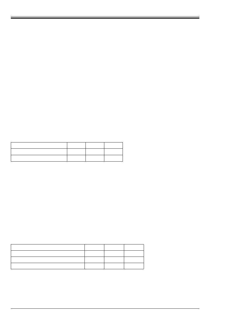
ENV 1997-1:1994
50
© BSI 03-2000
— the smaller diameter trial piles are fabricated and installed in the same way as the piles used for the
foundation;
— the trial pile is instrumented in such a manner that the base and shaft resistances can be derived
separately from the measurements.
The approach should be used with caution for open-ended driven piles because of the influence of the
diameter on the mobilisation of the end bearing resistance of a soil plug in the pile.
(4)P In the case of a pile foundation subjected to downdrag, the pile resistance at failure or at a
displacement which equals the criterion for the verification of the ultimate limit state determined from the
load test results shall be corrected by subtracting the measured or the most unfavourable design positive
skin friction force in the compressible stratum from the forces measured at pile head.
(5) During the load test, positive skin friction will be developed along the total length of the pile and should
be considered in accordance with 7.3.2.2. The maximum load applied to the working test pile should be in
excess of the sum of the design external load plus twice the downdrag.
(6)P When deriving the ultimate characteristic bearing resistance R
ck
from values R
cm
measured in one or
several pile load tests, an allowance shall be made for the variability of the ground and the variability of
the effect of pile installation. As a minimum, both conditions (a) and (b) of Table 7.1 shall be satisfied using
the equation:
Table 7.1 — Factors ß to derive R
ck
(7) The systematic and random components of the variations in the ground should be distinguished in the
interpretation of pile load tests. Account of the systematic components of ground variability can be made
by considering different zones of homogeneous conditions or a trend of ground conditions with the position
on the site. The records of the installation of the test pile(s) should be checked, and any deviation from the
normal execution conditions should be accounted for. Such variations should be covered in part by a correct
selection of the test piles.
(8)P In order to derive the ultimate design bearing resistance, the characteristic value, R
ck
, should be
divided into components of base resistance, R
bk
, and shaft resistance, R
sk
, such that:
(9) The ratio of these components may be derived from the load test results, e.g. when measurements of
these components have been performed, or estimated using the methods of 7.6.3.3.
(10)P The design bearing resistance, R
cd
, shall be derived from:
where *
b
and *
s
, are taken from Table 7.2.
Table 7.2 — Values of *
b
, *
s
, and *
t
(11) Normally the load test only provides the pile load versus settlement and time versus settlement
diagrams without distinction between point and shaft resistance. Therefore, it is often not possible to
distinguish between the partial factors for the assessment of the design value of base resistance and
shaft resistance. Instead a partial factor on the ultimate characteristic pile resistance R
ck
may be taken as
the ¾
t
values given in Table 7.2.
R
ck
= R
cm
/ß
(7.2)
Number of load tests
1
2
> 2
(a) Factor ß on mean R
cm
[1.5]
[1.35]
[1.3]
(b) Factor ß on lowest R
cm
[1.5]
[1.25]
[1.1]
R
ck
= R
bk
+ R
sk
(7.3)
R
cd
= R
bk
/ *
b
+ R
sk
/ *
s
(7.4)
Component factors
*
b
*
s
*
t
Driven piles
[1.3]
[1.3]
[1.3]
Bored piles
[1.6]
[1.3]
[1.5]
CFA (Continuous flight auger) piles
[1.45]
[1.3]
[1.4]
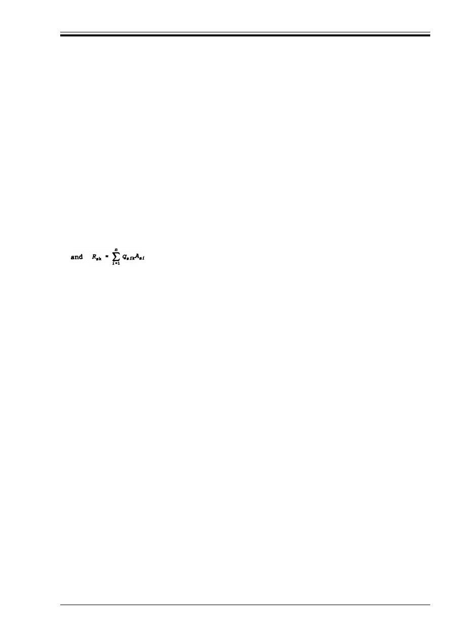
ENV 1997-1:1994
© BSI 03-2000
51
7.6.3.3 Ultimate bearing resistance from ground test results
(1)P The design bearing resistance, R
cd
, of a pile shall be found from:
where:
(2)P R
bd
and R
sd
should be derived from:
where the following symbols are used:
(3)P The values of *
b
and *
s
, shall be taken from Table 7.2.
(4)P The characteristic values q
bk
and q
sik
shall be derived from calculation rules based on established
correlations between the results of static load tests and the results of field or laboratory ground tests. These
calculation rules shall be devised such that ultimate bearing resistances using the characteristic values q
bk
and q
sik
do not exceed the measured ultimate bearing resistances used for establishing the correlation
divided by [1.5], on average.
(5)P The calculation rules shall be established on the basis of comparable experience as defined in 1.4.2.
(6) In assessing the validity of a calculation rule, the following items should be considered:
— soil type, including grading, mineralogy, angularity, density, preconsolidation, compressibility and
permeability;
— installation of the pile, including method of boring or driving, (or other method of installation), length,
diameter and material;
— method of ground testing.
(7)P The strength of a zone of ground above and below the base of the pile shall be taken into account when
calculating the base resistance of a pile.
(8) The zone of ground which influences the base resistance extends several diameters above and below the
pile toe. In the design, account should be taken of weak ground in this zone which has a relatively large
influence on the base resistance.
If weak ground is present at a depth of less than 4 times the base diameter below the base of the pile, a
punching failure mechanism should be considered.
(9)P For open-ended driven tube or box piles with openings of more than 500 mm in any direction, without
special devices inside the tube or box to induce plugging, the base resistance shall be limited to the smaller
of:
— the shearing resistance between the ground plug and the inside face of the tube or box;
— the base resistance derived using the cross sectional area of the base.
R
cd
= R
bd
+ R
sd
(7.5)
R
bd
is the design base resistance;
R
sd
is the design shaft resistance.
R
bd
= R
bk
/ *
b
and
R
sd
= RR
sk
/ *
s
(7.6)
where:
R
bk
= q
bk
· A
b
(7.7)
R
bk
and R
sk
the characteristic values of the base and shaft resistances;
A
b
the nominal plan area of the base of the pile;
A
si
the nominal surface area of the pile in soil layer i;
q
bk
the characteristic value of the resistance per unit area of the base;
q
sik
the characteristic value of the resistance per unit area of the shaft in layer i.

ENV 1997-1:1994
52
© BSI 03-2000
(10)P If piles with oversized base plates are installed, the possible adverse effect of the oversized plate on
the base and shaft resistance of the piles shall be considered.
7.6.3.4 Ultimate bearing resistance from pile driving formulae
(1)P If pile driving formulae are used to assess the ultimate bearing resistance of individual compression
piles in a foundation, the validity of the formulae shall have been demonstrated by previous experimental
evidence of good performance or static load tests on the same type of pile, of similar length and
cross-section, and in the similar ground conditions.
(2)P Pile driving formulae shall only be used if the stratification of the ground has been determined.
(3)P In the design, the number of piles to be redriven shall be specified. If redriving gives lower results,
these shall be used as the basis for ultimate bearing resistance assessment. If redriving gives higher
results, these may be taken into consideration.
(4) Redriving should usually be carried out in silty soils, unless local comparable experience has shown it
to be unnecessary.
7.6.3.5 Ultimate bearing resistance from wave equation analysis
(1)P Where wave equation analysis is used to assess pile bearing resistance of individual compression piles
the validity of the analysis shall have been demonstrated by previous evidence of acceptable performance
on static load tests on the same pile type of similar length and cross section and in similar soil conditions.
The input energy level during the dynamic load testing shall be high enough to allow for an appropriate
interpretation of the pile capacity at a correspondingly high enough strain level.
(2)P The input parameters in the wave equation analysis may be subject to modification where dynamic
pile testing of trial piles is carried out.
(3) Dynamic pile testing may supply a greater insight into actual hammer performance and dynamic
ground parameters.
(4)P Wave equation analysis shall normally only be used where stratification of the ground has been
determined by borings and field tests.
7.6.4 Settlement of pile foundations
(1)P Settlements under serviceability and ultimate limit state conditions shall be assessed and compared
against the relevant limiting values for the movement given in 2.4.5.
(2)P In cases where ultimate limit states may occur in supported structures before the ultimate bearing
resistance of piles is fully mobilised, the procedures of 7.6.3 for derivation of characteristic and design
values shall also be applied to the whole of the load-settlement curve, with the same numerical factors, and
the same treatment of downdrag.
(3)P The assessment of settlement shall include the following components:
— the settlement of a single pile;
— the additional settlement due to group action.
The settlement analysis shall include an estimate of the differential settlements that may occur.
7.7 Piles in tension
7.7.1 General
(1)P The design of piles in tension shall be consistent with the design rules given in 7.6, where applicable.
Design rules specifically for foundations involving piles in tension are presented in this section.
7.7.2 Ultimate tensile resistance
7.7.2.1 General
(1)P To demonstrate that the foundation will support the design load with adequate safety against failure
in tension, the following inequality shall be satisfied for all ultimate limit state load cases and load
combinations:
F
td
k R
td
(7.8)
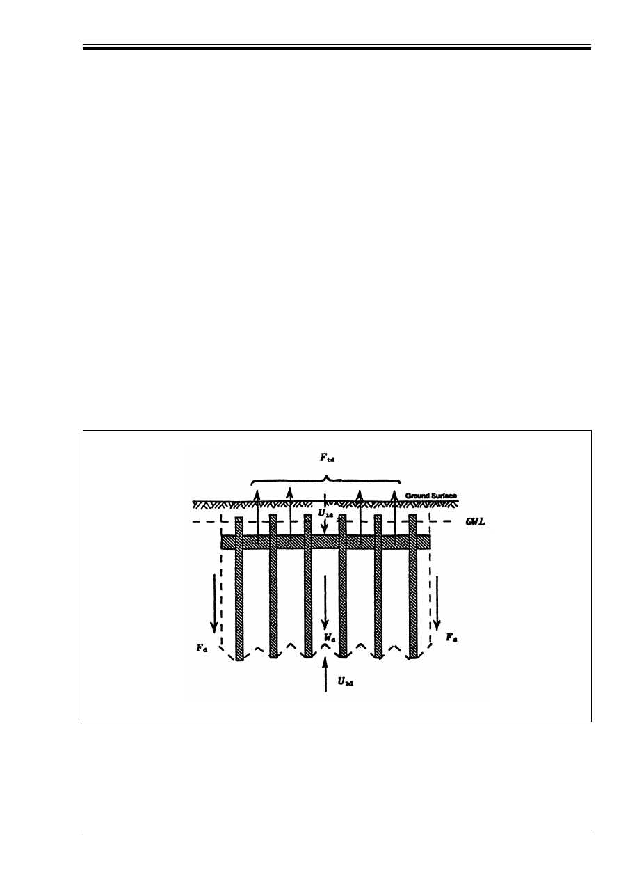
ENV 1997-1:1994
© BSI 03-2000
53
where:
(2)P For tension piles, two failure mechanisms shall be considered:
— pull out of the piles from the ground mass;
— uplift of the block of the ground containing the piles.
(3) For isolated tension piles or a group of tension piles, failure may occur by pulling out of a cone of ground
especially for a pile with an oversized base or rock socket.
(4)P To demonstrate that there is adequate safety against failure of piles in tension by uplift of the block
of soil containing the piles, as illustrated in Figure 7.1, the following inequality shall be satisfied for all
ultimate limit state load cases and load combinations:
where:
(5) Normally the block effect will govern the design tensile resistance if the distance between the piles is
equal to or smaller than the square root of the product of the pile length and the pile diameter.
(6)P The group effect, which may reduce the effective vertical stresses in the soil and hence the shaft
resistance of individual piles in the group, shall be considered when assessing the tensile resistance of a
group of piles.
F
td
is the ultimate limit state axial design tensile load and;
R
td
is the ultimate limit state design tensile resistance of the pile foundation.
F
td
k W
d
– (U
2d
– U
1d
) + F
d
(7.9)
F
td
is the design tensile force acting on the group of piles;
W
d
is the design weight of the soil block (including the water) and the piles;
F
d
is the design shear resistance at the boundary of the block of soil;
U
1d
is the design downward force due to the water pressure on the top of the pile foundation;
U
2d
is the design upward force due to the water pressure on the base of the soil block.
Figure 7.1 — Uplift failure of a group of piles in tension
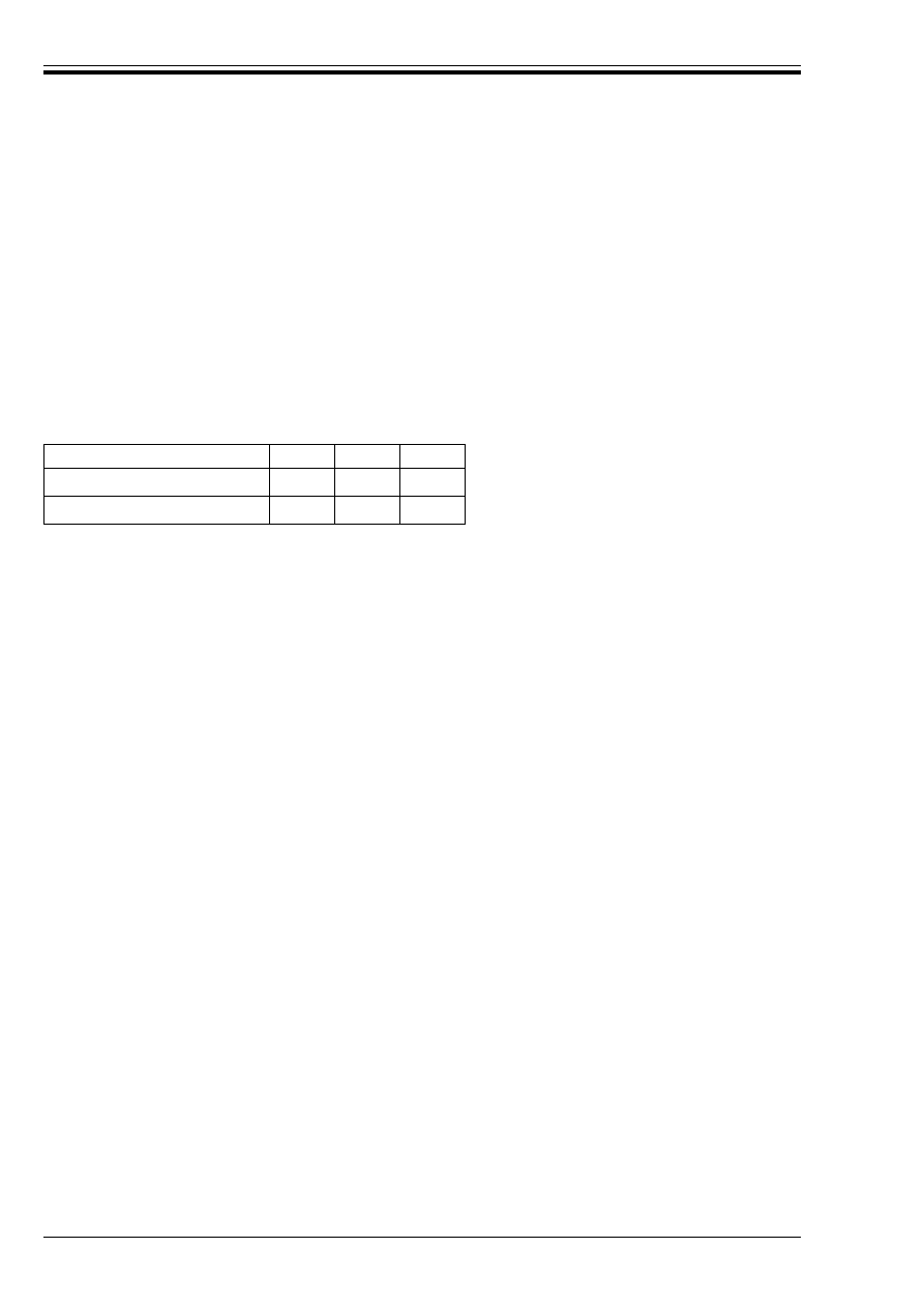
ENV 1997-1:1994
54
© BSI 03-2000
(7)P The severe adverse effect on the tensile resistance of cyclic loading and reversals of load shall be
considered.
(8) Comparable experience based on pile load tests should be applied to appraise this effect.
7.7.2.2 Ultimate tensile resistance from pile load tests
(1)P Pile load tests to determine the ultimate tensile resistance R
t
of an isolated pile shall be carried out in
accordance with 7.5 and with regard to the clauses in 7.6.3.2.
(2)P When deriving the ultimate characteristic tensile resistance R
tk
from values R
tm
measured in one or
several pile load tests, an allowance shall be made for the variability of the ground and the variability of
the effect of pile installation. As a minimum, both conditions (a) and (b) of Table 7.3 shall be satisfied using
the equation:
Table 7.3 — Factors to derive R
tk
(3) Normally when piles are to be loaded in tension, more than one pile should be tested. In the case of a
large number of tension piles, at least 2 % should be tested.
The records of the installation of the test pile(s) should be checked, and any deviation from the normal
construction conditions should be accounted for in the interpretation of the pile load test results.
(4)P The design tensile resistance, R
td
, shall be derived from:
where: *
m
= [1.6].
(5)P For pile groups, the effect of interaction shall be accounted for when deriving the tensile resistance
from the results of load tests on individual test piles.
7.7.2.3 Ultimate tensile resistance from ground test results
(1)P Calculation methods based on ground test results shall only be used when they have been proved by
load tests on similar piles, of similar length and cross-section, under comparable soil conditions.
(2)P The design value of the tensile resistance of an isolated tension pile or of a group of tension piles from
soil strength parameters shall be evaluated considering the shearing resistance between the pile and the
soil in the strata which contribute to the tensile resistance of the pile.
(3) Annex G gives a sample calculation model for the tensile resistance of individual or grouped piles.
7.7.3 Vertical displacement
(1)P Vertical displacements under serviceability limit state conditions shall be assessed and compared
against the relevant limiting values for the movement.
(2) This assessment should follow the general principles of 7.6.4. In general, checking against the ultimate
tensile resistance ensures that the vertical displacements will not cause damage to the structure and that
a serviceability limit state will not occur. However, in some situations, very severe criteria may be given
for the serviceability limit state and a separate check of the displacements may be required.
7.8 Transversely loaded piles
7.8.1 General
(1)P The design of piles subjected to transverse loading shall be consistent with the design rules given
in 7.6, where applicable. Design rules specifically for foundations involving piles subjected to transverse
loading are presented in this section.
R
tk
= R
tm
/ ß
(7.10)
Number of load tests
1
2
> 2
(a) Factor ß on mean R
tm
[1.5]
[1.35]
[1.3]
(b) Factor ß on lowest R
tm
[1.5]
[1.25]
[1.1]
R
td
= R
tk
/ *
m
(7.11)

ENV 1997-1:1994
© BSI 03-2000
55
7.8.2 Ultimate transverse load resistance
7.8.2.1 General
(1)P To demonstrate that a pile will support the design transverse load with adequate safety against
failure, the following inequality shall be satisfied for all ultimate limit state load cases and load
combinations:
where:
(2) One of the following failure mechanisms should be considered:
— for short piles, rotation or translation as a rigid body;
— for long slender piles, bending failure of the pile accompanied by local yielding and displacement of
the soil near the top of the pile.
(3)P The group effect shall be considered when assessing the resistance of transversely loaded piles.
(4) A transverse load applied to a group of piles may result in a combination of compression, tension, and
transverse forces in the individual piles.
7.8.2.2 Ultimate transverse load resistance from pile load tests
(1)P Pile head horizontal displacement tests shall be carried out in accordance with 7.5 and with regard to
the clauses in 7.6.3.2, where applicable.
(2) Contrary to the load test procedure described in 7.5, it is normally unnecessary to continue tests on
transversely loaded piles to a state of failure. The magnitude and line of action of the test load should
simulate the design loading of the pile.
(3)P An allowance shall be made for the variability of the ground particularly over the top few metres of
the pile when choosing the number of piles for testing and when deriving the design transverse resistance
from load test results.
(4) The data about the installation of the test pile(s) should be checked, and any deviation from the normal
construction conditions should be accounted for in the interpretation of the pile load test results. For pile
groups the effect of interaction and head fixity should be accounted for when deriving the transverse
resistance from the results of load tests on individual test piles.
7.8.2.3 Ultimate transverse load resistance from ground test results and pile strength parameters
(1)P The transverse resistance of a pile or pile group shall be calculated using a compatible set of structural
axial forces, bending moments, shear forces, ground reactions and displacements.
(2)P The analysis of a transversely loaded pile shall include the possibility of structural failure of the pile
in the ground in the zone below the ground surface, in accordance with 7.9.
(3) The calculation of the transverse load resistance of a long slender pile may be carried out using the
theory of a beam loaded at the end and supported by a deformable medium characterised by a horizontal
modulus of subgrade reaction.
(4)P The degree of freedom of rotation of the piles at the connection with the structure shall be taken into
account when assessing the transverse resistance of piles.
7.8.3 Transverse displacement
(1)P The assessment of the transverse displacement of the top of a pile foundation shall take into account:
— the stiffness of the ground and its variation with strain level;
— the flexural stiffness of the individual piles;
— the moment fixity of the piles at the connection with the structure;
— the group effect;
— the effect of load reversals or of cyclic loading.
F
trd
k R
trd
(7.12)
F
trd
is the ultimate limit state design transverse load and;
R
trd
is the ultimate limit state design resistance against transverse loads, taking into account the
effect of any compressive or tensile axial loads.

ENV 1997-1:1994
56
© BSI 03-2000
7.9 Structural design of piles
(1)P Piles shall be verified against structural failure in accordance with 2.4.
(2)P The structure of piles shall be designed to accommodate all the situations to which the piles will be
subjected, both during construction, including transportation and driving when applicable, and in use.
Piles subject to tension loads shall be designed to carry the full tensile force over their whole length when
necessary.
(3)P The structural design shall accommodate construction tolerances as specified for the type of pile, the
action components and the performance of the foundation.
(4)P Slender piles passing through water or thick deposits of very weak soil shall be checked against
buckling.
(5) For piles which are completely embedded in the ground, failure by buckling is not likely to occur.
According to established practice, buckling should be checked for piles in soil layers with characteristic
undrained strength of less than 15 kPa.
7.10 Supervision of construction
(1)P A pile installation plan shall be the basis for the construction work.
(2) The plan should give the following design information:
— the pile type with designation if standardized or Technical Approval otherwise;
— the location and inclination of each pile and tolerances on position;
— pile cross section;
— pile length;
— number of piles;
— required pile load carrying capacity;
— pile toe level (with respect to a fixed datum within or near the site), or the required penetration
resistance;
— installation sequence;
— known obstructions;
— any other constraints on piling activities.
(3)P The installation of all piles shall be monitored and records shall be made at the site and as the piles
are installed. A record signed by the supervisor of the work and the pile manufacturer shall be kept for each
pile.
(4) The record for each pile should include the following, where appropriate:
— pile type and installation equipment;
— pile number;
— pile cross section, length and (for concrete piles) reinforcement;
— date and time of installation (including interruptions to the construction process);
— concrete mix, volume of concrete used and method of placing for cast-in-situ piles;
— specific weight, pH, Marsh viscosity and fines content of bentonite slurry (when used);
— pumping pressures of the grout or concrete, internal and external diameters, pitch of screw and
penetration per revolution (for continuous flight auger piles or other injection piles);
— for driven piles, the values of driving resistance measurements such as weight and drop or power
rating of hammer, blow frequency and number of blows for at least the last 0.25 m penetration;
— the power take-off of vibrators (where used);
— the torque applied to the drilling motor (where used);
— for bored piles, the strata encountered in the borings and the condition of the base, if the performance
of the base is critical;
— obstructions encountered during piling;
— deviations of positions and directions and as-built elevations.

ENV 1997-1:1994
© BSI 03-2000
57
(5)P Records shall be kept for at least a period of five years after completion of the works. As-built record
plans shall be compiled after completion of the piling and kept with the construction documents.
(6)P If site observations or inspection of records reveal uncertainties with respect to the quality of installed
piles, additional investigations shall be carried out to determine the as-built conditions of the piles and
whether remedial measures are necessary. These investigations shall include either redriving or pile
integrity tests, in combination with soil mechanics field tests adjoining the suspected piles, and static pile
load tests.
(7)P Tests shall be used to examine the integrity of piles for which the quality is sensitive to the installation
procedures if the procedures cannot be monitored in a reliable way.
(8) Dynamic low strain integrity tests can be used for a global evaluation of piles that might have severe
defects or that may have caused a serious loss of strength in the soil during construction. Since defects like
insufficient quality of concrete and thickness of concrete cover, affecting the long term performance of a
pile, often cannot be found by dynamic tests, other tests such as sonic tests, vibration tests or coring may
be needed in supervising the execution.

ENV 1997-1:1994
58
© BSI 03-2000
Section 8. Retaining structures
8.1 General
(1)P The provisions of this chapter apply to structures which retain ground, similar material or water.
Material is retained if it is kept at a slope steeper than it would eventually adopt if no structure were
present. Retaining structures include all types of walls and support systems in which structural elements
are combined with soil or rock.
(2) In considering the design of retaining structures it may be appropriate to distinguish between the
following three main types of retaining structures:
— gravity walls are walls of stone or plain or reinforced concrete, having a base footing with or without
heel, ledge or buttress. The gravity of the wall itself, sometimes including stabilising soil or rock masses,
plays a significant role in the support of the retained material. Examples of such walls include concrete
gravity walls having constant or variable thickness, spread footing reinforced concrete walls, buttress
walls, etc.;
— embedded walls are relatively thin walls of steel, reinforced concrete or timber, supported by anchors,
struts and/or passive earth pressure. The bending capacity of such walls plays a significant role in the
support of the retained material while the role of the weight of the wall is insignificant. Examples of such
walls include: Cantilever steel sheet pile walls, anchored or strutted steel or concrete sheet pile walls,
diaphragm walls, etc.;
— composite retaining structures include walls composed of elements from the above two types of walls.
A large variety of such walls exists. Examples include double sheet pile wall cofferdams, earth structures
reinforced by tendons, geotextiles or grouting, structures with multiple rows of ground anchors or soil
nails, etc.
8.2 Limit states
(1)P A list of limit states to be considered shall be compiled. As a minimum the following limit states shall
be considered for all types of retaining structures:
— loss of overall stability;
— failure of a structural element such as a wall, anchor, wale or strut or failure of the connection
between such elements;
— combined failure in ground and in structural element;
— movements of the retaining structure which may cause collapse or affect the appearance or efficient
use of the structure, nearby structures or services which rely on it;
— unacceptable leakage through or beneath the wall;
— unacceptable transport of soil grains through or beneath the wall;
— unacceptable change to the flow of groundwater.
(2)P In addition the following limit states shall be considered for gravity retaining structures and for
composite retaining structures:
— bearing resistance failure of the soil below the base;
— failure by sliding at the base of the wall;
— failure by toppling of the wall.
and for embedded retaining structures:
— failure by rotation or translation of the wall or parts thereof;
— failure by lack of vertical equilibrium of the wall.
(3)P For all types of retaining structures combinations of the above mentioned limit states shall be
considered.
(4) Design of gravity retaining structures often encounters the same type of problems encountered in the
design of spread foundations and embankments and slopes. When considering the limit states for gravity
retaining structures the principles of chapter 6 should therefore be applied as appropriate. Special care
should be taken to account for bearing capacity failure of the ground below the base of the wall under loads
with large eccentricities and inclinations, cf. 6.5.4.

ENV 1997-1:1994
© BSI 03-2000
59
8.3 Actions, geometrical data and design situations
8.3.1 Actions
(1)P In selecting the actions for calculation of limit states, the actions listed in 2.4.2 shall be considered.
8.3.1.1 Weight of backfill material
(1)P Design values for the unit weight of backfill material shall be estimated on the basis of knowledge of
the material available for backfilling. The Geotechnical Design Report shall specify the checks which shall
be made during the construction process to verify that the actual field values are no worse than those
assumed in the design.
8.3.1.2 Surcharges
(1)P Determination of design values for surcharges shall take account of the presence on or near the ground
surface of nearby buildings, parked or moving vehicles or cranes, stored granular material, goods,
containers, etc.
(2) Care is needed in the case of repeated surcharge loading such as crane rails supported by a quay wall.
The pressures induced by such surcharges may significantly exceed those due to the first loading or those
resulting from static application of a load of equal magnitude.
8.3.1.3 Weight of water
(1)P Design values for unit weight of water shall reflect whether the water is fresh, saline or charged with
chemicals or contaminants to an extent that the normal value needs amendment.
(2) Local conditions such as salinity and the content of mud may significantly influence the unit weight of
water.
8.3.1.4 Wave forces
(1)P Design values for wave and wave impact forces shall be selected on the basis of locally available data
for the climatic and hydraulic conditions at the site of the structure.
8.3.1.5 Supporting forces
(1)P The components of forces caused by prestressing operations shall be regarded as actions. Design
values shall be selected taking into account the effect of overstressing the anchor and the effect of a
relaxation of the anchor.
8.3.1.6 Collision forces
(1)P Determination of design values for impact loads shall take account of the energy absorbed by the
retaining system on impact.
(2) For lateral impacts on retaining walls, it is normally necessary to consider the increased stiffness
exhibited by the retained ground when resisting an impact on the face of the wall. Furthermore the risk of
the occurrence of liquefaction due to lateral impact on embedded walls should be investigated.
(3)P The impact load of an ice floe colliding with a retaining structure shall be calculated on the basis of
the compressive strength of the ice and the thickness of the ice floe. The salinity and homogeneity of the
ice shall be considered in calculating the compressive strength.
8.3.1.7 Temperature effects
(1)P Design of retaining structures shall take into account the effect of abnormal temperature differences
over time and space.
(2) The effects of changes in temperature should especially be considered when determining the loads in
struts and props.
Fire effects are dealt with in the Structural Fire Design Parts of the material related Eurocodes.
(3)P The design values for ice forces acting on retaining structures from a sheet of ice covering water shall
be calculated taking into account:
— the initial temperature of the ice before warming begins;
— the rate at which the temperature increases;
— the thickness of the ice.
(4)P Special precautions such as selection of suitable backfill material, drainage or insulation shall be
taken to prevent ice lenses forming in the ground behind retaining structures.

ENV 1997-1:1994
60
© BSI 03-2000
8.3.2 Geometrical data
(1)P Design values for the geometrical data shall be derived in accordance with the principles stated
in 2.4.5.
8.3.2.1 Ground surfaces
(1)P Design values for the geometrical data concerning the backfill behind the retaining structure shall
take account of the variation in the actual field values. The design values shall also take account of
anticipated excavation or possible scour in front of the retaining structure.
(2) Where the stability of a retaining wall depends on the passive resistance of the ground in front of the
structure, the ground level of the passive soil should be lowered by an amount %
a
, in ultimate limit state
calculations. For a cantilever wall, %
a
should equal (10 %) of its height and for a supported wall, %
a
should
equal (10 %) of the height beneath the lowest support with %
a
limited to a maximum of 0.5 m.
8.3.2.2 Water levels
(1)P The selection of design values for the geometrical data which determine the regime of free water and
the groundwater regime shall be made on the basis of locally available data for the hydraulic and
hydrogeological conditions at the site of the retaining structure.
(2)P Account shall also be taken of the effect of variations of permeability on the groundwater regime. The
possibility of adverse water pressure conditions due to the presence of perched or artesian water tables
shall be considered.
8.3.3 Design situations
(1)P For the design of retaining structures the following items shall be considered:
— variation in soil properties with time and space;
— variations in water levels and pore water pressure in time;
— variation in actions and in the way they are combined;
— excavation, scour or erosion in front of the retaining structure;
— backfilling behind the retaining structure;
— the effect, if anticipated, of future structures and surcharge loadings;
— ground movements due to subsidence, frost actions, etc.
(2) For waterfront structures ice forces and wave forces need to be applied simultaneously at the same
point.
8.4 Design and construction considerations
(1)P In the design, both ultimate and serviceability limit states shall be considered, using a combination of
the approaches mentioned in 2.1.
(2) The complexity of the interaction between the ground and the retaining structure sometimes makes it
difficult to design a retaining structure in detail before the actual execution begins. In these cases it is
appropriate to use the observational method for the design of retaining structures.
For many earth retaining structures, a critical limit state occurs when the wall is displaced far enough to
cause damage to nearby structures or services. Although collapse of the wall may not be imminent, the
degree of damage caused in this way may considerably exceed a serviceability limit state in the supported
structure. However, the design methods and factors of safety required by this code for ultimate limit state
design are often sufficient to prevent the occurrence of this type of limit state provided the soils involved
are at least medium dense or firm, and adequate construction methods and sequences are adopted. Special
concern is, however, required by some highly overconsolidated clay deposits in which large at rest
horizontal stresses may induce substantial movements in a wide area around excavations.
(3)P The design of retaining structures shall take account of the following items where appropriate:
— the effects of constructing the wall, including:
— the provision of temporary support to the sides of excavations;
— the changes of in situ stresses and resulting ground movements caused both by the wall installation
and construction;
— disturbance of the ground due to driving or boring operations;

ENV 1997-1:1994
© BSI 03-2000
61
— provision of access for construction;
— required degree of watertightness of the finished wall;
— the practicability of constructing the wall to reach a stratum of low permeability and so to form a
water cut-off. The resulting equilibrium ground water flow problem shall be assessed;
— the practicability of forming ground anchors in adjacent ground;
— the practicability of excavating between the propping of retaining walls;
— the ability of the wall to carry vertical load;
— ductility of structural components.
(4) As far as possible, retaining walls should be designed in such a way that adequate warning of danger
(i.e. approaching an ultimate limit state) is given by visible signs. The design should guard against the
occurrence of brittle failure, e.g. sudden collapse without conspicuous preliminary deformations;
— access for maintenance of the wall itself and any associated drainage measures;
— the appearance and durability of the wall and the anchorages;
— for sheet piling, the need for a section stiff enough to be driven to the design penetration without loss
of interlock;
— the stability of borings or slurry trench panels whilst they are open;
— for fill, the nature of materials available and the means used to compact them adjacent to the wall, in
accordance with 5.3.
(5)P If the safety and serviceability of the design depends on the successful performance of drainage, the
consequences of failure of the drainage system shall be considered, having regard for both damage to life
and cost of repair. One of the following conditions (or a combination of them) shall apply:
— a maintenance programme for the drainage system shall be specified and the design shall allow access
for this purpose;
— it shall be demonstrated both by comparable experience and by assessment of the water which will
emerge, that the drainage system will operate adequately without maintenance.
(6) The seepage quantities, pressures and eventual chemical content of the emerging water should be
considered.
8.5 Determination of earth and water pressures
8.5.1 Design earth pressures
(1)P Determination of design earth pressures shall take account of the mode and amount of movement and
strain which is acceptable and which may take place for the retaining structure at the limit state under
consideration.
(2) In the following context the words “earth pressure” will also denote the pressure from soft and
weathered rocks and includes the pressure of groundwater.
Pressure from granular material stored in silos should be calculated from ENV 1991-4 Eurocode 1 Actions
on silo’s.
(3)P Calculations of the magnitudes and directions of design earth pressures shall further take account of:
— the surcharge on and slope of the ground surface;
— the inclination of the wall to the vertical;
— the water tables and the seepage forces in the ground;
— the amount and direction of the movement of the wall relative to the ground;
— the horizontal as well as vertical equilibrium for the entire retaining structure;
— the shear strength and unit weight of the ground;
— the rigidity of the wall and the supporting system;
— the wall roughness.
(4) The amount of mobilised wall friction and adhesion is a function of:
— the strength parameters of the ground;
— the friction properties of the wall-ground interface;

ENV 1997-1:1994
62
© BSI 03-2000
— the direction of movements of the wall with respect to the ground and the amount of relative
wall-ground movement;
— the ability of the wall to support the vertical forces implied by the wall friction and adhesion.
The amount of shear stress which can be mobilised at the wall-ground interface is limited by the
wall-ground interface parameters ¸ and a. For a completely smooth wall ¸ = o and a = o and for a completely
rough wall ¸ = Ì and a = c.
A concrete or steel sheet piled wall supporting sand or gravel material normally may be assumed to
have ¸ = kÌ and a = o, where Ì due to the disturbance at the ground wall interface should not exceed the
critical state angle of friction of the ground and where k should not exceed the value 2/3 for precast concrete
or steel sheet piling while it may assume the value 1 for concrete cast against soil. A steel sheet pile in clay
under undrained conditions normally should be assumed to have ¸ = o and a = o immediately after driving.
Regeneration may take place over a period of time.
(5)P The design magnitudes and directions of earth pressures shall be calculated in accordance with the
specifications given in Table 2.1 using design values of ground parameters which are appropriate to the
limit state being considered.
(6) The design value of an earth pressure at an ultimate limit state is generally different from its value at
a serviceability limit state. These two values are determined from two fundamentally different
calculations. Consequently, when expressed as an action, earth pressure can not be characterised by a
single characteristic value.
(7)P In the case of retaining structures for rock masses, calculations of the ground pressure shall take
account of the effect of discontinuities with particular attention to their orientation, aperture, roughness
and the mechanical characteristics of any fill material.
(8)P In the case of retaining structures for swelling ground, calculation of the earth pressure shall take
account of the swelling potential of the ground.
(9) The swelling pressures from cohesive soils depend on plasticity, placement water content and hydraulic
boundary conditions.
8.5.2 At rest values of earth pressure
(1)P When no movement of the wall relative to the ground takes place, the earth pressure shall be
calculated from the state of stress at rest. The determination of the at rest state shall take account of the
stress history of the ground.
(2) At rest conditions will normally exist in the ground behind a retaining structure when the movement of
the structure is less than 5 .10
–4
· H for normally consolidated soil.
For a horizontal ground surface, the at rest pressure coefficient K
o
, which expresses the ratio between the
horizontal and vertical (i.e. overburden) effective stresses, may be determined by:
where R
oc
denotes the overconsolidation ratio. The formula should not be used for extreme high values
of R
oc
.
If the ground is shelving upward from the wall by an angle ¶ k ̽ with the horizon, the horizontal
component of the effective earth pressure Ö
ho
may be related to the effective overburden pressure by the
ratio K
o
taken equal to:
The direction of the earth pressure force may then be assumed to be parallel to the ground surface.
8.5.3 Limit values of earth pressure
(1)P Limit values of earth pressure are passive or active pressures which occur when the shear strength of
the ground is fully mobilized and there is no impediment to the necessary type and amount of movement
of ground or wall.
Annex G gives sample procedures for calculating limit values of earth pressure.
(2)P When struts, anchors or similar elements impose kinematical conditions on the structure, the limit
values yield only a possible and not necessarily most adverse (or economical) distribution of earth
pressures.
K
o
= (1 – sin ̽) · ÆR
oc
(8.1)
K
o
= K
o
(1 + sin ¶)
(8.2)

ENV 1997-1:1994
© BSI 03-2000
63
(3)P It shall be demonstrated that vertical equilibrium can be achieved for the assumed pressure
distributions. If not, the wall friction parameters must be reduced on one side of the wall.
8.5.4 Intermediate values of earth pressure
(1)P Intermediate values of earth pressure occur when the wall movements are insufficient to mobilise the
limit values. The determination of the intermediate value of earth pressure shall take account of the
amount of wall movement and its direction relative to the ground.
(2) The movement needed for development of an active limit state in noncohesive ground of at least medium
dense consistency is of the following order of magnitude:
where:
The intermediate values of earth pressures may be
calculated using various empirical rules, spring
constant methods, finite element methods, etc.
8.5.5 Compaction effects
(1)P An additional earth pressure is incurred if the wall is backfilled in layers and the fill is compacted. The
determination of the additional earth pressure shall take account of the compaction procedure.
(2) Measurements indicate that the additional pressure depends on the applied energy, the thickness of the
compacted layers, and the travel pattern of the compaction plant. However, compaction is reduced when
the next layer is placed and compacted. When backfilling is complete, the excess pressure acts normally on
the upper part of the wall.
(3)P Appropriate compaction procedures shall be applied during execution with the aim of avoiding
excessive earth pressures which may lead to excessive movements for the structure.
8.5.6 Water pressures
(1)P Determination of design water pressures shall take account of the water levels above the ground and
the groundwater level.
(2)P When checking the ultimate and serviceability limit states, the water pressures shall be accounted for
in the combinations of actions in accordance with 2.4.2 and 8.4 (5)P.
(3)P For structures retaining soil of medium or low permeability (silts and clays), water pressures shall be
assumed to act behind the wall corresponding to a water table assumed to be at a level no lower than the
top face of the material with low permeability unless a reliable drainage system is installed or infiltration
is prevented.
(4)P Where sudden changes in a free water level may occur, both the non-steady condition occurring
immediately after the change in water table and the steady condition shall be examined.
(5)P Where no special drainage or flow prevention measures are taken, the possible effects of water filled
tension or shrinkage cracks shall be considered.
(6) For these circumstances, in retained cohesive soils, the design total pressure should normally not be
less than the pressure of water increasing hydrostatically from zero at the ground surface.
8.6 Ultimate limit state design
8.6.1 General
(1)P The design of retaining structures shall be checked at the ultimate limit state using the design actions
and design situations appropriate to that state, as specified in 8.3.
(2)P All relevant limit modes shall be considered.
(3) As a minimum, limit modes of the types illustrated in Figure 8.1 to Figure 8.6 for the most commonly
used retaining structures should be considered.
— rotation about the top
0.002 · H
— rotation about the toe
0.005 · H
— translative motion
0.001 · H
H
is the height of the wall.
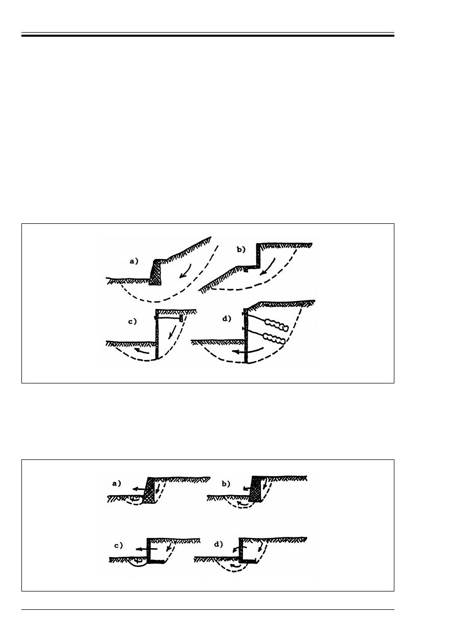
ENV 1997-1:1994
64
© BSI 03-2000
(4)P Calculations for ultimate limit states shall establish that equilibrium can be achieved using the design
actions and the design strengths as specified in 2.4.2 and 2.4.3. Compatibility of deformations in the
materials involved in a calculation shall be considered in assessing design strengths.
(5)P Upper or lower design values shall be used for the strength of the ground, whichever is more adverse.
(6)P Calculation methods may be used which redistribute earth pressure in accordance with the relative
displacements and stiffnesses of ground and structural elements.
(7)P For fine grained soils, both short term and long term behaviour shall be considered.
(8)P For walls subject to differential water pressures, safety against failure due to hydraulic instability
(erosion) shall be checked.
8.6.2 Overall stability
(1)P The principles in section 9 shall be used as appropriate to demonstrate that an overall stability failure
will not occur and that the corresponding deformations are sufficiently small.
(2) As a minimum, limit modes of the types illustrated in Figure 8.1 should be considered taking
progressive failure and liquefaction into account.
8.6.3 Foundation failure of gravity walls
(1)P The principles of section 6 shall be used as appropriate to demonstrate that a foundation failure is
sufficiently remote and that corresponding deformations will be small. Both bearing resistance and sliding
shall be considered.
Figure 8.1 — Examples of limit modes for overall stability of retaining structures
Figure 8.2 — Examples of limit modes for foundation failures of gravity walls
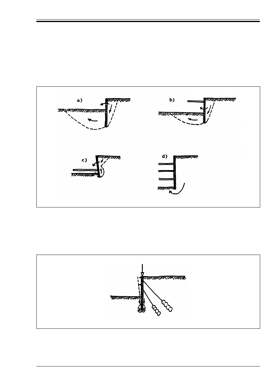
ENV 1997-1:1994
© BSI 03-2000
65
(2) As a minimum, limit modes of the types illustrated in Figure 8.2 should be considered.
8.6.4 Rotational failure of embedded walls
(1)P It shall be demonstrated by equilibrium calculations that embedded walls have sufficient penetration
into the ground to prevent rotational failure.
(2) As a minimum, limit modes of the types illustrated in Figure 8.3 should be considered.
(3)P The design magnitude and direction of shear stress between the soil and the wall shall be consistent
with the relative vertical displacement which would occur in the design situation.
8.6.5 Vertical failure of embedded walls
(1)P It shall be demonstrated that vertical equilibrium can be achieved using the design soil strengths and
design vertical forces on the wall.
(2) As a minimum, the limit mode of the type illustrated in Figure 8.4 should be considered.
(3)P Where downward movement of the wall is considered, upper design values shall be used in this
calculation for prestressing forces, such as those from ground anchors, which have a vertical downward
component.
Figure 8.3 — Examples of limit modes for rotational failures of embedded walls
Figure 8.4 — An example of a limit mode for vertical failure of embedded walls
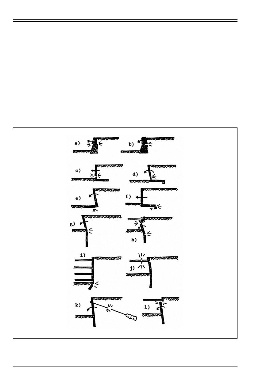
ENV 1997-1:1994
66
© BSI 03-2000
(4)P The design magnitude and direction of shear stress between the soil and the wall shall be consistent
with the check for rotational failure.
(5) Vertical and rotational equilibrium should be checked with the same design values for shear stress on
the wall.
(6)P If the wall acts as the foundation of a structure, vertical equilibrium shall be checked using the
principles of section 7.
8.6.6 Structural design of retaining structures
(1)P Retaining structures including their supporting structural elements such as anchors and props shall
be verified against structural failure in accordance with 2.4.2.
It shall be demonstrated that equilibrium can be achieved without exceeding the design strengths of the
wall and of supporting structural elements suchs as props and anchors.
(2) As a minimum, limit modes of the types illustrated in Figure 8.5 should be considered.
(3)P For each ultimate limit state it shall be demonstrated that the required strengths can be mobilised in
the ground and the structure with compatible deformations.
Figure 8.5 — Examples of limit modes for structural failure of retaining structures
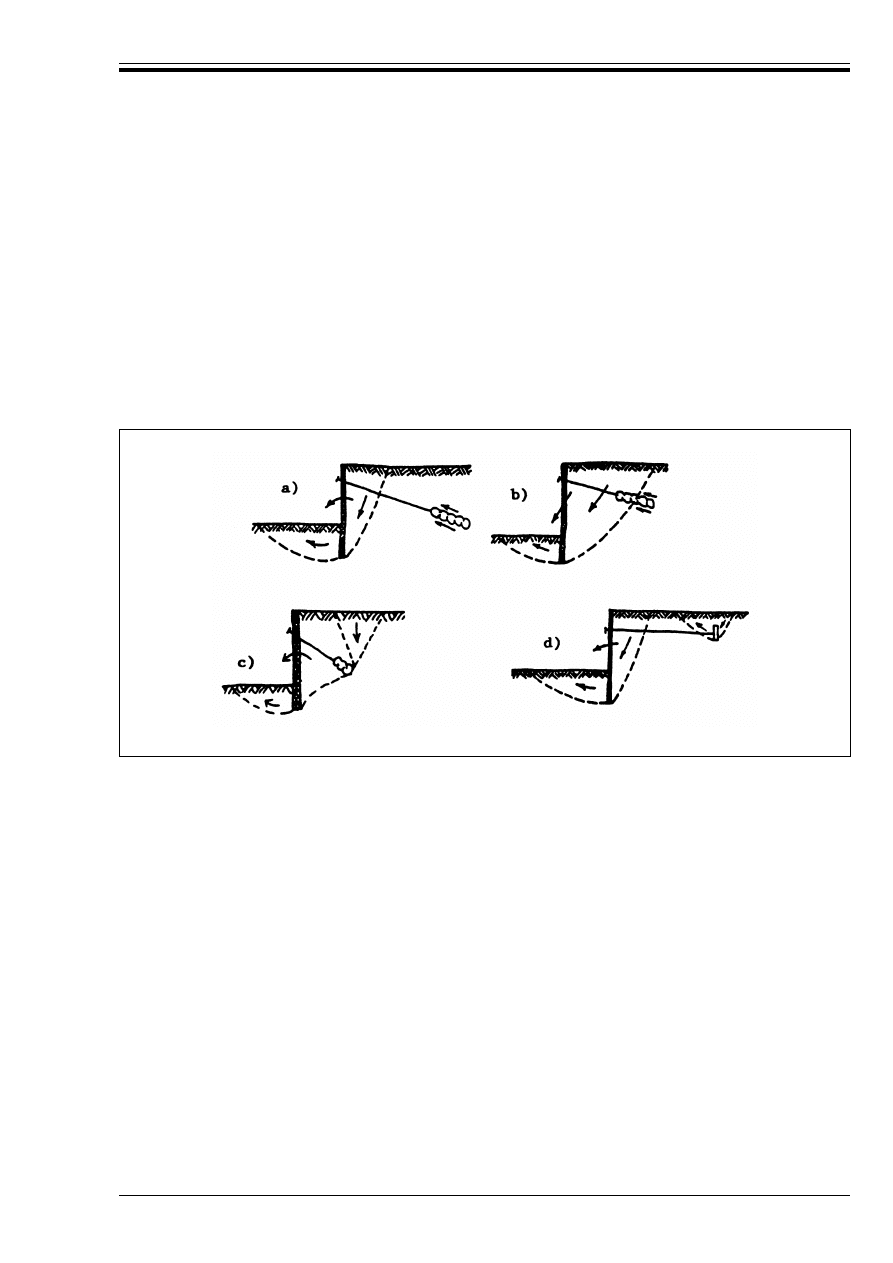
ENV 1997-1:1994
© BSI 03-2000
67
(4) In structural elements, reduction in strength with deformation, due to effects such as cracking of
unreinforced sections, large rotations at plastic hinges or local buckling of steel sections should be
considered in accordance with the material-related Eurocodes. In the ground, loss of strength due to
dilation in dense granular soils and formation of polished surfaces in clays should be considered.
The design action effects (moments, internal forces, etc.) in retaining structure elements shall be calculated
on the basis of design earth pressures and design ground resistances and shall then be multiplied by a
model factor *
sd
. The design resistance of the retaining structure element shall be calculated from the
relevant material-related Eurocode.
(5)P For each ultimate limit state, it shall be demonstrated that the required strengths can be mobilised in
the ground and the structure with compatible deformations.
8.6.7 Failure by pull-out of anchors
(1)P It shall be demonstrated that equilibrium can be achieved without pull-out failure of ground anchors.
(2) Grouted anchors should be designed in accordance with section 8.8. As a minimum, limit modes of the
types illustrated in Figure 8.6[a), b), c)] should be considered.
For “dead men” anchors, the failure mode illustrated in Figure 8.6 d) should be considered. Calculation of
the pull-out capacity of the anchor should be based on passive resistance with no allowance for wall
friction ¸.
Where anchors are closely spaced, forming parallel or overlapping sets, interaction between anchors and
the possible failure of the complete group should be considered.
8.7 Serviceability limit state
8.7.1 General
(1)P The design of retaining structures shall be checked at the serviceability limit state using the
appropriate design situations as specified in 8.3.
8.7.2 Displacements
(1)P Limiting values for the allowable displacements for walls and the ground adjacent to them shall be
established in accordance with 2.4.5, taking into account the tolerance of supported structures and services
to displacement.
(2)P A cautious estimate of the distortion and displacement of retaining walls, and the effects on supported
structures and services, shall always be made on the basis of comparable experience. This estimate shall
include the effects of construction of the wall. It shall be verified that the estimated displacements do not
exceed the limiting values.
Figure 8.6 — Examples of limit modes for failure by pull-out of anchors

ENV 1997-1:1994
68
© BSI 03-2000
(3)P If the initial cautious estimate of displacement exceeds the limiting values, the design shall be justified
by a more detailed investigation including displacement calculations.
(4)P If the estimated displacements exceed 50 % of the limiting values, a more detailed investigation
including displacement calculations shall be undertaken in the following situations.
— where nearby structures and services are unusually sensitive to displacement;
— where the wall retains more than 6 m of soil of low plasticity or 3 m of soils of high plasticity;
— where the wall is supported by soft clay within its height or beneath its base;
— where comparable experience is not well established.
(5)P Displacement calculations shall take account of the stiffness of the ground and structural elements
and the sequence of construction.
(6) The behaviour of materials assumed in displacement calculations should be calibrated by comparable
experience with the same calculation model. If linear behaviour is assumed, the stiffnesses adopted for the
ground and structural materials should be appropriate for the degree of deformation computed.
Alternatively, complete stress-strain models of the materials may be adopted.
8.7.3 Vibrations
(1)P The provisions of 6.6.2 also apply to retaining structures.
8.7.4 Structural serviceability limit states
(1)P Design earth pressures for the serviceability limit state check of the structural elements shall be
derived using characteristic values of all soil parameters.
(2) The assessment of design earth pressures should take into account the initial stress, stiffness and
strength of the ground and the stiffness of the structural elements.
The design earth pressures should be derived taking account of the allowable deformation of the structure
at its serviceability limit state. These will not necessarily be limiting active and passive values.
8.8 Anchorages
8.8.1 General
(1)P This section is concerned with any type of anchorage used to support a retaining structure by
transmitting a tensile force to a load-bearing formation of soil or rock.
(2) Such anchorages include
— installations consisting of an anchor head, a free anchor length and a fixed anchor length, established
by grouting;
— installations consisting of an anchor head and a fixed anchor length, but without a free anchor length
(soil nails);
— installations consisting of an anchor head, a free anchor length and a reinforced concrete or steel
anchor;
— installations consisting of a screw anchor and an anchoring cap.
Ground anchorages may be employed as temporary or as permanent elements of a retaining structure.
8.8.2 Anchorage design
(1)P Anchorage design shall take into account all circumstances during the foreseeable design life of the
anchorage. The corrosion and creep of permanent anchorages shall be considered.
Preferably anchorage systems for which successful long-term experience has been documented with respect
to performance and durability should be used.
(2)P The ground investigation prior to the design and execution of anchorage shall include those ground
formations outside the actual site if the tensile forces are transferred there.
(3)P Anchorages which are going to be in use for more than two years shall be designed as permanent
anchors.
(4)P To check an anchorage against the ultimate limit states, three failure mechanisms shall be analysed’
— the failure of the tendon or anchor head in terms of their material strength or the failure of bonding
at internal interfaces;

ENV 1997-1:1994
© BSI 03-2000
69
— the failure of the anchorage at the tendon-grout or grout-ground interface; the design pull-out
resistance shall exceed the anchorage design load;
— the overall stability failure of the structure including the anchorages according to the principles given
in 8.6.
(5) The pull-out resistance for a given design situation depends on the geometry of the anchorage, but the
transfer of stresses to the surrounding ground is influenced by the execution technique.
This particularly holds for grouted anchorages where the procedure and to a lesser extent the chosen
drilling technique and method of flushing is important.
(6)P Steel tendons and bars used for anchors shall be designed according to the principles of ENV 1993-1
Eurocode 3 Design of steel structures.
(7) The minimum free anchor length should be about 5 m.
8.8.3 Construction considerations
(1)P The connection between the tendon and the wall shall be able to adjust to the movements occurring in
service.
(2)P Permanent anchorages shall be protected against corrosion over the full length of the tendon and the
anchor head. The environmental conditions during the lifetime of the anchor shall be taken into account.
(3) The following criteria are considered to be indicative levels in excess of which special precautions are
needed against water aggressiveness to concrete or hardened cement grout:
Besides the protection against corrosion, a mechanical protection is usually required for permanent
anchors to avoid damage of the corrosion protection during transportation, installation and stressing.
8.8.4 Anchorage testing
(1)P The load carrying resistance of an anchorage shall be evaluated from test results and from local
experience. The following load tests may be carried out on-site on anchors:
— assessment tests;
— acceptance tests.
(2)P Assessment tests shall be carried out in advance of the main contract or on selected working
anchorages during the course of construction with the aim of assessing the suitability of the anchorage
system to provide the necessary anchorage resistance under the soil conditions in question. They also
provide criteria for the acceptance tests.
(3)P Acceptance tests shall be carried out to demonstrate that each of the anchorages installed has the
capacity to carry the load assumed in the design.
(4)P The method used for the installation of anchorages submitted to onsite assessment tests shall be fully
documented in accordance with 8.8.7.
(5)P Between the time of installation of an anchorage and the beginning of a load test, adequate time shall
be allowed to ensure that the required quality of the bond at the tendon-grout (or, where relevant,
grout-encapsulation) and grout-ground interface is achieved.
(6)P It shall be checked that all equipment and measuring apparatus used for anchorage testing is
sensitive, accurate and in perfect working order.
8.8.5 Assessment tests
(1)P At least one assessment test shall be carried out for each distinct condition for ground and construction
unless comparable experience exists.
— pH values
less than 5,5;
— carbon acid CO
2
more than 40 mg/l;
— ammonium NH
4
more than 30 mg/l;
— magnesium
more than 1 000 —mg/l;
— sulphate SO
4
more than 200 mg/l;
— hardness
less than 30 mg CaO/1.

ENV 1997-1:1994
70
© BSI 03-2000
(2) On large anchorage projects the number of assessment tests per ground condition should be at least 1 %
for temporary anchorages where failure will have few serious consequences and at least 2 % in the case of
permanent anchorage or temporary anchorages where the consequences of failure are serious.
(3)P The test duration shall be sufficient to ensure that prestress or creep fluctuations stabilize within
tolerable limits.
(4)P When deriving the ultimate characteristic anchorage resistance R
ak
from values R
am
measured in one
or more assessment tests, an allowance shall be made for the variability of the ground and the variability
of the effect of pile installation. As a minimum, both conditions (a) and (b) of Table 8.1 shall be satisfied
using the equation:
Table 8.1 — Conversion factors ß to derive R
ak
The anchorage resistance, R
a
, obtained from the assessment tests shall be equal to the lowest of the loads
corresponding to the first two failure mechanisms referred in 8.8.2 (4)P and the creep limit load.
(5) The systematic and random components of the variations in the ground should be distinguished in the
interpretation of the assessment tests.
Account of the systematic components of ground variability, can be made considering different zones of
homogeneous conditions or a trend of ground conditions with position on the site. Then the data about the
installation of the anchorages should be checked, and any deviations from the normal execution conditions
should be accounted for. Such variations should be covered in part by a correct selection of the assessment
tests.
(6)P The design resistance, R
a
, shall be derived from:
The design resistance is then compared with the largest ultimate limit state design load which is going to
be carried by the anchorage.
(7)P The assessment test procedure, particularly with respect to the number of loading steps, the duration
of these steps and the application of load cycles, shall be such that conclusions can be drawn about the
anchorage resistance, the creep limit load, and the apparent free tendon length.
8.8.6 Acceptance tests
(1)P All grouted anchorages shall be subjected to an acceptance test before they become operational and
prior to the lock-off procedure.
(2)P Acceptance testing shall be performed in compliance with standard procedures and acceptance criteria
which are derived from the results of the assessment tests with the aim of proving the ability of each
anchorage to support the maximum limit state load.
(3)P The test procedure shall provide confirmation of the apparent free tendon length and that the
relaxation of anchor force after lock-off will be acceptably small.
(4) The acceptance test loading may be used to pre-load the anchorage in order to minimise future
relaxation of anchor force.
8.8.7 Supervision of construction and monitoring
(1)P An anchorage installation plan shall be available on site containing the technical specification related
to the anchorage system to be used.
(2) An anchorage installation plan may contain the following information, as appropriate:
— the anchorage type with designation if standardized by European Technical Approval;
R
ak
= R
am
/ ß
(8.4)
Number of assessment tests
1
2
> 2
(a) ß on mean R
am
[1.5]
[1.35]
[1.3]
(b) ß on lowest R
am
[1.5]
[1.25]
[1.1]
R
a
= R
ak
/ *
m
(8.4)
where:
*
m
= [1.25] for temporary anchorages and;
*
m
= [1.5] for permanent anchorages.

ENV 1997-1:1994
© BSI 03-2000
71
— number of anchorages;
— the location and orientation of each anchorage and tolerances in position;
— anchorage length;
— date and time of installation of each anchorage;
— for grouted anchorage; material, pressure, grouted volume, grouting length, grouting time;
— required anchorage load carrying capacity;
— installation of the chosen corrosion protection;
— installation technique (drilling, placing, bonding and stressing);
— known obstructions;
— any other constraints on anchoring activities.
(3)P The installation of all anchorages shall be monitored and records shall be made at the site and as the
anchorages are installed. A signed record shall be kept for each anchorage.
(4)P If inspection reveals uncertainties with respect to the quality of installed anchorages, additional
investigations shall be carried out to determine the as-built conditions of the anchorages.
(5)P Records shall be kept after completion of the works. As-built record plans shall be compiled after
completion of the anchorages and kept with the construction documents. Certificates for all materials and
their relevant properties shall also be held.

ENV 1997-1:1994
72
© BSI 03-2000
Section 9. Embankments and slopes
9.1 Scope
(1)P The provisions of this chapter apply to embankments and slopes but not to dykes and dams.
(2)P Placement and compaction of fill are considered in section 5 and retaining structures which provide
support for slopes are considered in section 8.
9.2 Limit states
(1)P In order to fulfil the fundamental requirements for embankments and slopes of stability, limited
deformation, durability and limitation of damage to nearby structures or services, the following limit states
shall be considered:
— loss of overall stability or bearing resistance;
— failure due to internal erosion;
— failure due to surface erosion or scour;
— failure due to hydraulic uplift;
— deformations (including those due to creep) of the embankment or slope and their foundations which
cause structural damage in adjacent structures, roads or services;
— rockfalls;
— deformations of the embankment or slope, including those due to creep, which cause loss of
serviceability;
— surface erosion.
9.3 Actions and design situations
(1)P In selecting the actions for calculation of limit states, the list in 2.4.2 (4)P shall be considered.
(2)P The effects of the following processes shall be considered:
— construction processes, such as excavation in front of the slope or the placing of an embankment, the
effect of vibrations caused by rock blasting, piling, etc.;
— the effect of structures which are expected to be placed on or near the embankment or slope after its
completion;
— the effect of the new slope on existing work;
— the effect of any previous or continuing movement of existing slopes;
— the effects of overtopping, waves and rain on the slopes and crest of embankments (erosion);
— effects of the temperature on the embankment slopes (shrinkage);
— animal activities causing clogging of drains or digging of holes in the ground.
(3)P The design free water level in front of the slope and the design groundwater level, or their combination,
shall be chosen from the available hydrological data to give the most unfavourable conditions that could
occur in the design situation being considered. The possibility of failure of drains, filters or seals shall be
considered.
(4) For embankments along water the most unfavourable hydraulic conditions are normally steady seepage
for the highest possible groundwater level and rapid drawdown of the free water level.
(5)P In deriving design distributions of pore water pressure, account shall be taken of the possible range of
anisotropy and variability of the soil.
9.4 Design and construction considerations
(1)P Embankments and slopes shall be designed and constructed taking into account experience of slopes
and cuttings in similar ground.

ENV 1997-1:1994
© BSI 03-2000
73
(2) Embankments built on soft cohesive soils are normally raised in increments of height. The thickness of
these layers and the speed of construction should be determined during design in order to prevent loss of
stability of the slopes or bearing resistance of the foundation during construction. Consolidation time can
be calculated only approximately. The rate of consolidation of the soft soil layers should therefore be
checked during construction by measuring settlements. Measurement of pore pressures may also be
required, the next layer of fill being placed when excess pore pressures have fallen below safe values, which
are to be stated in the design report. The results of the settlements measurements are to be used as a check
on this procedure. If vertical drains are installed to accelerate the consolidation, and hence the
construction, special care should be taken with respect to the location of the pore pressure measuring
devices. They should be located in the centre of the grid of vertical drains. The observational method
described in 2.7 should be implemented.
(3)P Slope surfaces exposed to serious erosion shall be protected.
(4) Slopes may be sealed or planted, or protected artificially. For slopes with berms, a drainage system
within the bern may be needed. Trees or scrubs should generally not be planted on river and lake
embankments.
9.5 Ultimate limit state design
9.5.1 Loss of overall stability
(1)P In analysing the stability of an embankment or ground slope (soil or rock masses) all possible failure
modes shall be considered.
(2) The mass of soil or rock bounded by the failure surface is normally treated as a rigid body or as several
rigid bodies moving simultaneously. Alternatively, stability may be checked by finding a statically
admissible stress field or using the finite element method. Failure surfaces or interfaces between rigid
bodies may have a variety of shapes including planar, circular and more complicated shapes.
Where ground or embankment material is relatively homogeneous and isotropic in strength, it will usually
be sufficient to assume circular failure surfaces.
For slopes in layered soils with considerable variations of shear strength, special attention should be paid
to the layers with smaller shear strength. This may require analysis of non-circular failure surfaces.
In jointed materials, including hard rock and some soils, the shape of the failure surface depends on the
discontinuities and may also pass through intact material. This may require analysis of three dimensional
wedges.
(3)P The equilibrium of the body bounded by any possible failure surface shall be verified when the actions
and the shear strength parameters of the ground are assigned their design values in accordance with 2.4.2
and 2.4.3.
(4) In soils and soft rocks which do not exhibit marked strength anisotropy, the method of slices may be
used. The method shall verify the overall moment and vertical stability of the sliding mass. If horizontal
equilibrium is not checked, interslice forces should be assumed to be horizontal.
A conservative analysis may be performed using earth pressures in embankments calculated according to
section 8 and bearing resistance of the foundation from section 6.
(5)P In computations of overall stability for slopes and embankments, Case A of 2.4 may generally be
omitted.
(6) Unless there is abnormal uncertainty about soil density, it is not necessary to distinguish between
favourable and unfavourable gravity loads in slope stability calculations.
9.5.2 Deformations
(1)P The design shall show that the deformation of the embankment or slope under the design actions will
not cause severe damage to structures, transportation networks or services sited on or near the
embankment or slope.
(2)P Deformation within the embankment shall be considered together with that of the ground beneath it.

ENV 1997-1:1994
74
© BSI 03-2000
(3) The settlement of an embankment on a compressible soil foundation may be calculated using the
principles of 6.6.1. Special attention should be paid to the settlement-time relationship which includes both
consolidation and secondary settlement. Attention should also be paid to the possibility of the occurrence
of differential settlements. Since the analytical and numerical methods available at present do not usually
provide reliable predictions of the-pre-failure deformation of a slope, the occurrence of ultimate limit states
may be avoided by either:
— limiting the mobilized shear strength, or;
— observing the movements and taking action to control them if this becomes necessary.
9.5.3 Superficial erosion, internal erosion and hydraulic uplift
(1)P If steady or temporary seepage of water is possible, the design shall ensure that failure will not be
caused by superficial erosion, internal erosion or hydraulic uplift.
(2) The measures most commonly used to ensure that superficial or internal erosion and hydraulic uplift
do not occur are:
— seepage control;
— protective filters;
— avoidance of the use of dispersive clays without the protection of adequate filters;
— slope revetments;
— inverted filters;
— relief wells;
— reduction of hydraulic gradient.
In addition, observations of the phreatic surface and of the rate of seepage can be made to check that the
slope is performing as intended.
9.5.4 Rockslides
(1)P The risk of slides in rockmasses shall be considered. The rockslides can be planar or rotational
depending on the rockmass structure.
(2) Prevention of rockslides can be obtained by providing stable inclination, anchoring, bolting, surface and
internal drainage etc.
9.5.5 Rockfalls
(1)P In rock, the risk of rockfalls caused by toppling, wedge failure or spalling shall be considered.
(2) Prevention of rockfalls may be achieved by such techniques as anchoring, bolting or shotcreting.
Alternatively rockfalls may be allowed to occur and the damage limited by trapping the falling rocks.
9.5.6 Creep
(1)P The risk of displacements of ground slopes due to creep shall be considered.
(2) Prediction of creep movements is normally difficult and the better prevention is to avoid the utilization
of susceptible areas.
9.6 Serviceability limit state design
(1)P The design shall show that the deformation of the embankment or slope under the design actions will
not cause loss of serviceability in structures, roads or services sited on or near the embankment or slope.
(2) Application rule 9.5.2 (3) for calculating the settlement of an embankment on a compressible soil layer
is also applicable here. Trial embankments may be useful for predicting the behaviour of embankments
where serviceability limit states must be prevented.
Compression of the fill due to its own weight or foundation loads will be small provided the fill is well
compacted and the foundation loads are light. The possibility of deformations due to changes in the
groundwater conditions should be considered. Special attention should be given to possible long term
consolidation settlements due to changes in the water content of the fill or the ground beneath the fill.

ENV 1997-1:1994
© BSI 03-2000
75
9.7 Monitoring
(1)P Embankments and slopes shall be monitored using appropriate equipment if either:
— it is not possible to prove by calculation or by prescriptive measures that all of the limit states given
in 9.2 will not occur or;
— the assumptions made in the calculations are not based on adequate and reliable data.
(2) Monitoring should follow the principles of section 4.
Monitoring should be used where knowledge is required of:
— groundwater levels or pore pressures in and beneath an embankment or slope so that an effective
stress analyses can be carried out, or checked;
— lateral and vertical movements of a moving soil and rock mass in order to predict further
deformations;
— the-depth and shape of the sliding surface in a developed slide in order to derive the ground strength
parameters for the design of remedial works;
— rates of movement in order to give warning of impending danger. In such cases a remote digital
readout for the instruments or a remote alarm system may be appropriate.
The construction of embankments on soft soil with low permeability shall be monitored and controlled by
means of pore pressure measurements in the soft layers and settlement measurements of the fill.
Monitoring should normally be employed for embankments placed in Geotechnical Category 3.

ENV 1997-1:1994
76
© BSI 03-2000
Annex A (informative)
Checklist for construction supervision and performance monitoring
The list which follows contains the more important items that should be considered when supervising
construction or monitoring the performance of the completed structure. The importance of the items will
vary from project to project. The list is not exhaustive. Items which refer to specific aspects of geotechnical
engineering or to specific types of works have been reported in the chapters of this code.
A.1 Construction supervision
A.1.1 General items to be checked
1) Verification of ground conditions and of the location and general lay-out of the structure.
2) Groundwater flow and pore pressure regime; effects of dewatering operations on groundwater table;
effectiveness of measures taken to control seepage inflow; internal erosion processes and piping;
chemical composition of groundwater; corrosion potential.
3) Movements, yielding, stability of excavation walls and base; temporary support systems; effects on
nearby buildings and utilities; measurement of soil pressures on retaining structures; measurement of
pore pressure variations resulting from excavation or loading.
4) Safety of workmen with the due consideration of geotechnical limit states.
A.1.2 Water flow and pore pressures
1) Adequacy of system to ensure control of pore water pressures in all aquifers where excess pressures
could affect stability of slopes or base of excavation, including artesian pressures in an aquifer beneath
the excavation; disposal of water from dewatering systems; depression of groundwater table throughout
entire excavation to prevent boiling or quick conditions, piping and disturbance of formation by
construction equipment; diversion and removal of rainfall or other surface waters.
2) Efficient and effective operation of dewatering system throughout the entire construction period
considering encrusting of well screens, silting, of wells or sumps; wear in pumps; clogging of pumps.
3) Control of dewatering to avoid disturbance of adjoining structures or areas; observations of
piezometric levels; effectiveness, operation and maintenance of water recharge systems if required.
4) Settlement of adjoining structures or areas.
5) Effectiveness of subhorizontal borehole drains.
A.2 Performance monitoring
1) Settlement at established time intervals of buildings and other structures including those due to
effects of vibrations, metastable soils.
Settlement observations shall be referred to a stable benchmark.
2) Lateral displacement, distortions especially those related to fills and stockpiles; soil supported
structures, such as buildings or large tanks; deep excavations channels.
3) Piezometric levels under buildings or in adjoining areas, especially if deep drainage or permanent
dewatering systems are installed or if deep basements are constructed.
4) Deflection or displacement of retaining structures considering: normal backfill loadings; effects of
stockpiles, fills or other surface loadings; water pressures.
5) Flow measurement from drains.
6) Special problems.
High temperature structures such as boilers, hot ducts, etc.; desiccation of clay or silt soils; monitoring
of temperatures; movements.
Low temperature structures, such as cryogenic installations or refrigerated areas: temperature
monitoring; ground freezing; frost heave, displacement; effects of subsequent thawing.
7) Watertightness.

ENV 1997-1:1994
© BSI 03-2000
77
Annex B (informative)
A sample analytical method for bearing resistance calculation
B.1 General
Approximate equations for the design vertical bearing resistance, derived from plasticity theory and
experimental results, may be used. Allowance should be made for the effects of the following:
— the strength of the ground, generally represented by the design values of c
u
, c½ and ̽;
— eccentricity and inclination of design loads;
— the shape, depth and inclination of the foundation;
— the inclination of the ground surface;
— groundwater pressures and hydraulic gradients;
— the variability of the ground, especially layering.
The following symbols are used in addition to those in 1.6 and 1.7:
B.2 Undrained conditions
The design bearing resistance is calculated from:
with the design values of dimensionless factors for:
— the shape of the foundation:
— the inclination of the load, caused by a horizontal load H:
i
c
= 0,5 (1 +
)
B.3 Drained conditions
The design bearing resistance is calculated from:
R/A½ = c½ · N
c
· s
c
· i
c
+ q½ · N
q
· s
q
· i
q
+ 0.5 · *½ · B½ · N
*
·
· ss
*
· i
*
(B.2)
with the design values of dimensionless factors for:
— the bearing resistance:
N
q
= e
Ï tanÌ
tan
2
(45. + ̽ /2)
N
c
= (N
q
– 1) cot ̽
N
*
= 2 (N
q
– 1) tan ̽ when ¸ U ̽ /2 (rough base)
$
the design base friction angle as discussed in 6.5.3;
q
the design total overburden pressure at the level of the foundation base;
q½
the design effective overburden pressure at the level of the foundation base;
*
½
the design effective unit weight of the soil below the foundation level, reduced
to *½ = * – *
w
(1 + l) in the case of an upward hydraulic gradient l;
B½
the design effective foundation width;
L½
the design effective foundation length;
A½ = B½ L½ the design effective foundation area, defined as the foundation base or, in the case of an
eccentric load, the reduced area of the foundation whose centroid is the point through
which the load resultant acts;
s, i
the design values of the dimensionless factors for the shape of the foundation and the
inclination of the load, respectively; the subscripts c, q and * indicate the influences due to
cohesion, the surcharge and the weight of the soil; these coefficients are only valid when
the shear parameters are independent of direction.
R /A½ = (2 + ;) c
u
s
c
i
c
+ q
(B.1)
s
c
= 1 + 0.2 (B½ /L½)
for a rectangular shape;
s
c
= 1,2
for a square or circular shape.
1 H/A
′
c
u
–

ENV 1997-1:1994
78
© BSI 03-2000
the shape of foundation:
— the inclination of the load, caused by a horizontal load H parallel to L½
i
q
= i
*
= 1 – H / (V + A½ c½ cot ̽)
i
c
= (i
q
· N
q
– 1) / (N
q
– 1)
— the inclination of the load, caused by a horizontal load H parallel to B½:
i
q
= (1 – 0.7 H /(V + A½ · c½ cot Ì))
3
i
*
= (1 – H / (V + A½ · c½ cot ̽))
3
i
c
= (i
q
· N
q
– 1) / (N
q
– 1)
The additional influences of embedment depth, inclination of the base of the foundation and of the ground
surface should also be considered.
Annex C (informative)
A sample semi-empirical method for bearing resistance estimation
To estimate the design bearing resistance of a foundation on soil semiempirically, in-situ tests such as the
pressuremeter test may be used. When using the pressuremeter the design bearing resistance of a
foundation subjected to a vertical load is related to the limit pressure of the soil by the linear function:
where the following symbols are used:
Annex D (informative)
Sample methods for settlement evaluation
D.1 Stress-strain Method
The total settlement of a foundation on cohesive or non-cohesive soils may be evaluated using the
stress-strain calculation method as follows:
— computing the stress distribution in the ground due to the loading from the foundation; this may be
derived on the basis of elasticity theory, generally assuming homogeneous isotropic soil and a linear
distribution of bearing pressure;
— computing the strain in the ground from the stresses using stiffness moduli values or other
stress-strain relationships determined from laboratory tests (preferably calibrated against field tests) or
field tests;
s
q
= 1 + (B½ /L½) sin̽
for a rectangular shape;
s
q
= 1 + sin̽
for a square or circular shape;
s
*
= 1 – 0.3 (B½ /L½)
for a rectangular shape;
s
*
= 0,7
for a square or circular shape;
s
c
= (s
q
· N
q
– 1)/(N
q
– 1) for rectangular, square or circular shape.
R/A½ = q + k
(C.1)
A½
the design effective foundation area as in Annex B;
q
the design total overburden pressure at the level of the foundation base;
k
the bearing resistance factor with numerical values in the range of 0,8 to 3 depending on the type
of soil, the embedment depth and the shape of the foundation;
the design net equivalent limit pressure; the net limit pressure
is defined for a pressuremeter
test as the difference (p
1
– p
0
) between the limit pressure p
1
and the at rest horizontal earth
pressure p
o
at the level of the test; p
o
may be determined from an estimate of the at rest earth
pressure coefficient K
o
and from the values of the effective overburden pressure q½ and the pore
water pressure u as p
o
= K
o
q½ + u.
p
*
1
p
*
1
p
*
1

ENV 1997-1:1994
© BSI 03-2000
79
— integrating the vertical strains to find the settlements; to use the stress-strain method a sufficient
number of points within the ground beneath the foundation should be selected and the stresses and
strains computed at these points.
D.2 Adjusted Elasticity Method
The total settlement of a foundation on cohesive or non-cohesive soil may be evaluated using elasticity
theory and an equation of the form:
where the following symbols are used:
The adjusted elasticity method should only be used if the stresses in the ground are such that no significant
yielding occurs and if the stress-strain behaviour of the ground may be considered to be linear. Great
caution is required when using the adjusted elasticity method in the case of non-homogeneous ground.
D.3 Settlements without drainage
The short-term components of settlement of a foundation, which occur without drainage, may be evaluated
using either the stress-strain method or the adjusted elasticity method. The values adopted for the stiffness
constants (such as E
m
) and Poisson’s ratio should in this case represent the undrained behaviour.
D.4 Settlements caused by consolidation
To calculate the settlement caused by consolidation, a confined one-dimensional deformation of the soil
may be assumed and the consolidation test curve is then used. Addition of settlements in the undrained
and consolidation state often leads to an overestimate of the total settlement, and empirical corrections
may be applied.
D.5 Time-settlement behaviour
With cohesive soils the rate of consolidation settlement before the end of primary consolidation may be
estimated approximately using consolidation parameters obtained from a compression test. However, the
rate of consolidation settlement should preferably be obtained using permeability values obtained from
insitu tests in accordance with 3.3.10.
s = p · B · f/E
m
(D.1)
p
the serviceability limit state bearing pressure linearly distributed on the base of the foundation,
which for normally consolidated cohesive soils should be reduced by the weight of the excavated
soil above the base; buoyancy effects should also be taken into account;
E
m
the design drained Young’s modulus of the deforming stratum for drained conditions. If no useful
settlement results measured at neighbouring similar structures in similar conditions are
available to evaluate E
m
, it may be estimated from the results of laboratory or in situ tests;
f
a coefficient whose value depends on the shape and dimensions of the foundation area, the
variation of stiffness with depth, the thickness of the compressible formation, Poisson’s ratio, the
distribution of the bearing pressure and the point for which the settlement is calculated;
B
the width of the foundation.

ENV 1997-1:1994
80
© BSI 03-2000
Annex E (informative)
A sample method for deriving presumed bearing resistance for spread
foundations on rock
For weak and broken rocks with tight joints, including chalk with porosity less than 35 %, presumed
bearing resistance may be derived from Figure E.1. This is based on the grouping given in Table E.1 with
the assumption that the structure can tolerate settlements equal to 0,5 % of the foundation width. Values
of presumed bearing resistance for other settlements may be derived by direct proportion. For weak and
broken rocks with open or infilled joints, reduced values of presumed bearing pressure should be used.
Table E.1 — Grouping of weak and broken rocks
For chalk with porosity greater than 35 %, values of presumed bearing resistance may be derived
from Table E.2.
Table E.2 — Classification and presumed bearing resistance
for high porosity chalk
Group
Type of rock
1
Pure limestones and dolomites
Carbonate sandstones of low porosity
2
Igneous
Oolitic and marly limestones
Well cemented sandstones
Indurated carbonate mudstones
Metamorphic rocks, including slates and schists
(flat cleavage/foliation)
3
Very marly limestones
Poorly cemented sandstones
Slates and schists (steep cleavage/foliation)
4
Uncemented mudstones and shales
Grade
Brief description
Presumed bearing
resistance kPa
V
Structureless remoulded chalk containing lumps
of intact chalk.
Dry chalk above the water table
125 to 250
IV
Rubbly partly-weathered chalk with bedding and
jointing. Joints 10 mm to 60 mm apart, open
to 20 mm, and often infilled with soft remoulded
chalk and fragments
250 to 500
III
Rubbly to blocky unweathered chalk.
Joints 60 mm to 200 mm apart, open to 3 mm,
and sometimes infilled with fragments
500 to 750
II
Blocky medium-hard (weak) chalk. Joints more
than 200 mm apart and closed
750 to 1 000
I
As for grade II, but hard (moderately weak) and
brittle
1 000 to 1 500
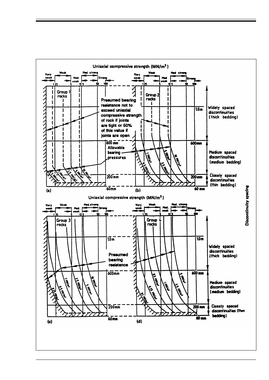
ENV 1997-1:1994
© BSI 03-2000
81
Figure E.1 — Presumed bearing resistance for square pad foundations bearing on rock
(for settlements not exceeding 0,5 % of foundation width). For types of rock in each of four
groups, see Table E.1. Presumed bearing resistance in hatched areas to be assessed after
inspection and/or making tests on rock
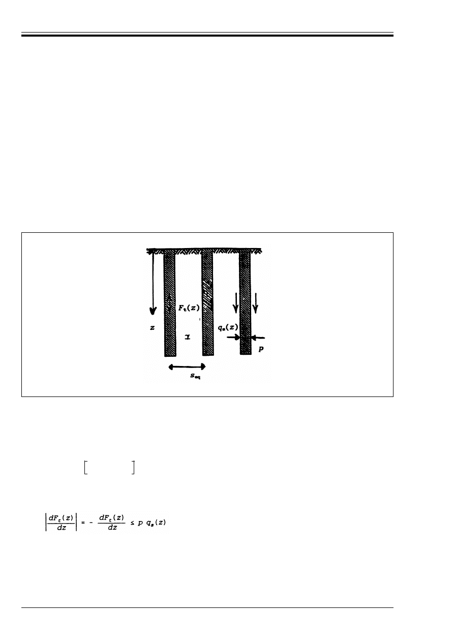
ENV 1997-1:1994
82
© BSI 03-2000
Annex F (informative)
A sample calculation model for the tensile resistance of individual or grouped
piles
The following calculation model, shown in Figure F.1, may be used to check the tensile resistance of
individual or grouped piles. The following symbols are used in addition to those in 1.6 and 1.7:
The design is satisfactory if a distribution of tension, F
t
(z) can be found which satisfies the following
requirements:
— At the top of the pile (z = 0): F
t
(0) = F
t
— At the base of the pile (z = L): F
t
(L) = 0
— For grouped piles, at all depths z, F
t
(z) is limited by the weight of soil above depth z:
— An allowance for shear forces on the perimeter of the group may be included.
— At all depths z, the gradient of F
t
(z) is limited by the shaft resistance:
— In homogeneous, ground, the resistant soil block always extends down to the depth of the pile base.
— When calculating q
s
(z) allowance should be made for its dependence on the effective vertical stresses
in the ground between the piles. These stresses are influenced in an unfavourable way by the pile tensile
load F
t
.
— The value of q
s
(z) may be smaller for tensile piles than for compression piles and this effect should to
be considered.
F
t
is the tensile load on each pile;
F
t
(z) is the tension in pile at depth z;
q
s
(z) is the design shaft resistance at depth z;
u(z)
is the design pore water pressure at depth z;
p
is the pile perimeter;
s
eq
is the pile spacing assuming a regular array of piles or equivalent spacing for piles placed in an
non-regular array.
Figure F.1 — Model to check tensile resistance of individual or grouped piles
F
t
(z) k F
t
–
(F.1)
(F.2)
J
o
z
∫
dz u z
( )
–
s 2
eq
ENV 1997-1:1994
© BSI 03-2000
83
Annex G (informative)
Sample procedures to determine limit values of earth pressure
Three earth pressure coefficients are defined, K
*
for the ground weight as defined by the unit weights *, K
q
for vertical surface loading q and K
c
for ground cohesion c, all depending on the angle of shearing resistance
of the ground.
At any point at distance z down the face of the wall (or vertical depth z cosÚ) from the ground surface, the
total pressure components are then Ö (normal) and Ù (tangential), with Ù positive when the pressure from
the ground on the wall is directed toward the top:
For drained states and non-saturated soils:
in which:
For drained states in saturated soils an approximate formulation is the following:
in which:
For undrained states:
in which:
In layered soils, the coefficients K may normally be determined by the friction angle at depth z only,
independent of the values at other depths.
In active state, tensile active stresses should never be considered as actions on retaining structures.
Explicit formulas for the earth pressure coefficients are not available for the general case. Two sample
procedures to determine earth pressure coefficients are given in the following.
Diagrams for vertical walls
For vertical walls, the values may be taken from Figure G.1, Figure G.2, Figure G.3 and Figure G.4.
Ö = Ö
½ = K
*
· *dz + K
q
· q½ + K
c
· c½
(G.1)
Ù = Ö
½ tan¸ + a
(G.2)
Ö
½
is the effective stress normal to the wall at depth z;
¸
is the angle of shearing resistance between ground and wall;
a½
is the effective wall adhesion.
Ö
= Ö
½ + u
z
(G.3)
(G.4)
Ù
= Ö½ tan¸ + a½
(G.5)
q½
is the effective surcharge pressure;
u
z
is the pore pressure on the failure surface at depth z · cosÚ below the top of the wall;
u
o
is the pore pressure at z = 0;
Ö
½
is the effective stress normal to the wall at depth z;
¸
is the angle of shearing resistance between ground and wall;
a½
is the effective wall adhesion.
Ö
= K
*
u
*dz + K
qu
q + K
cu
c
u
(G.6)
Ù
= a
u
(G.7)
K
*
u
= K
qu
= 1, when the wall is vertical and the ground surface is horizontal
q
= total surcharge pressure (including water pressure)
a
u
= undrained wall adhesion
z
o
∫
z
o
∫
ENV 1997-1:1994
84
© BSI 03-2000
Figure G.1 — Coefficients of active earth pressure (horizontal component) for horizontal
retained surface
Figure G.2 — Coefficients of passive earth pressure (horizontal component) for horizontal
retained surface
ENV 1997-1:1994
© BSI 03-2000
85
Figure G.3 — Coefficients of active earth pressure (horizontal component) for general case on
inclined backfill with wall friction
ENV 1997-1:1994
86
© BSI 03-2000
Figure G.4 — Coefficients of passive earth pressure (horizontal component) for general
case of inclined backfill with wall friction
ENV 1997-1:1994
© BSI 03-2000
87
Numerical procedure
The following procedure, which includes certain approximations on the safe side, may be used in all cases.
The procedure is stated for passive pressures in which case the strength parameters (represented in the
following by Ì, c, ¸, a) are inserted as positive values.
The following symbols are used in addition to those in 1.6 and 1.7, cf Figure G.5:
The interface parameters ¸ and a must be chosen so that:
a/c = tan ¸/tan Ì
The boundary condition at the soil surface involves 
o
which is the angle of incidence of an equivalent
surface load. With this concept the angle is defined from the vectorial sum of two terms, see Figure G.5:
— the actual distributed surface loading, q per unit of surface area, uniform but not necessarily vertical,
and;
— c cot Ì acting as normal load.
The angle 
o
is positive when the tangential component of q points toward the wall while the normal
component is directed toward the soil. If c = 0 while the surface load is vertical or zero, and for active
pressures generally, 
o
= ¶.
The angle m
t
is determined by the boundary condition at the soil surface:
m
t
is the angle from the soil surface direction, pointing away from the wall, to the tangent direction
of the intersecting slip line that bounds the moving soil mass, pointing out from the soil surface;
m
w
is the angle from wall normal to the tangent direction at the wall of the exterior slip line, positive
when the tangent points upwards behind the wall;
is the angle from the horizontal to the soil surface direction, positive when the soil surface rises
away from the wall;
Ú
is the angle between the vertical and the wall direction, positive when the wall is overhanging;
v
is the tangent rotation along the exterior slip line, positive when the soil mass above this slip line
is of a convex shape;
q
is a general uniform surcharge pressure, per area unit of the actual surface;
p
is a vertical uniform surcharge pressure, per area unit in a horizontal projection.
Figure G.5 — Definitions concerning surface load, geometry of slip line etc
(G.8)
ENV 1997-1:1994
88
© BSI 03-2000
The boundary condition at the wall determines m
w
by:
The angle m
w
is negative for passive pressures (Ì > 0) if the ratio sin ¸/sin Ì is sufficiently large, as
assumed for Figure G.5.
The total tangent rotation along the exterior slip line of the moving soil mass, see Figure G.5, is determined
by the angle v to be computed by the expression:
The coefficient K
n
for normal loading on the surface (i.e. the normal earth pressure on the wall from a unit
pressure normal to the surface) is then determined by the following expression in which v is to be inserted
in radians:
The coefficient for a vertical loading on the surface force per unit of horizontal area projection, is:
This expression is on the safe side. While the error is unimportant for active pressures it may be
considerable for passive pressures with positive values of ¶.
For Ì = 0 the following limit values are found:
cos 2m
t
= – sin ¶ cos ¶; cos 2m
w
= ;
K
q
= cos
2
¶; K
c
= 2v + sin 2m
t
+ sin 2m
w
;
(with É in radians) while for K
*
, a better approximation when Ì = 0 is:
For active pressures the same algorithm is used, with the following changes:
The strength parameters Ì, c, ¸ and a are inserted as negative values. The angle of incidence of the
equivalent surface load 
o
= ¶, mainly because of the approximations used for K
*
.
Both for passive and active pressures, the procedure assumes the angle of convexity to be positive:
É
U 0
If this condition is not (even approximately) fulfilled, e.g. for a smooth wall and a sufficiently sloping soil
surface when ¶ and Ì have opposite signs, it may be necessary to consider using other methods. This may
also be the case when irregular surface loads are considered.
(G.9)
v = m
t
+ ¶ – m
w
– Ú
(G.10)
(G.11)
K
q
= K
n
cos
2
(G.12)
and the coefficient for the cohesion term is:
K
c
= (K
n
– 1) cot Ì
(G.13)
For the soil weight an approximate expression is:
K* = K
n
cos ¶ cos (¶ – Ì)
(G.14)
(G.15)
p
c---
a
c---

blank

DD ENV
1997-1:1995
BSI
389 Chiswick High Road
London
W4 4AL
BSI — British Standards Institution
BSI is the independent national body responsible for preparing
British Standards. It presents the UK view on standards in Europe and at the
international level. It is incorporated by Royal Charter.
Revisions
British Standards are updated by amendment or revision. Users of
British Standards should make sure that they possess the latest amendments or
editions.
It is the constant aim of BSI to improve the quality of our products and services.
We would be grateful if anyone finding an inaccuracy or ambiguity while using
this British Standard would inform the Secretary of the technical committee
responsible, the identity of which can be found on the inside front cover.
Tel: 020 8996 9000. Fax: 020 8996 7400.
BSI offers members an individual updating service called PLUS which ensures
that subscribers automatically receive the latest editions of standards.
Buying standards
Orders for all BSI, international and foreign standards publications should be
addressed to Customer Services. Tel: 020 8996 9001. Fax: 020 8996 7001.
In response to orders for international standards, it is BSI policy to supply the
BSI implementation of those that have been published as British Standards,
unless otherwise requested.
Information on standards
BSI provides a wide range of information on national, European and
international standards through its Library and its Technical Help to Exporters
Service. Various BSI electronic information services are also available which give
details on all its products and services. Contact the Information Centre.
Tel: 020 8996 7111. Fax: 020 8996 7048.
Subscribing members of BSI are kept up to date with standards developments
and receive substantial discounts on the purchase price of standards. For details
of these and other benefits contact Membership Administration.
Tel: 020 8996 7002. Fax: 020 8996 7001.
Copyright
Copyright subsists in all BSI publications. BSI also holds the copyright, in the
UK, of the publications of the international standardization bodies. Except as
permitted under the Copyright, Designs and Patents Act 1988 no extract may be
reproduced, stored in a retrieval system or transmitted in any form or by any
means – electronic, photocopying, recording or otherwise – without prior written
permission from BSI.
This does not preclude the free use, in the course of implementing the standard,
of necessary details such as symbols, and size, type or grade designations. If these
details are to be used for any other purpose than implementation then the prior
written permission of BSI must be obtained.
If permission is granted, the terms may include royalty payments or a licensing
agreement. Details and advice can be obtained from the Copyright Manager.
Tel: 020 8996 7070.
Wyszukiwarka
Podobne podstrony:
Eurocode 7 Part 2 DDENV 1997 2 1999
Eurocode 2 Part 1,6 DDENV 1992 1 6 1994
Eurocode 7 Part 3 DDENV 1997 3 1999
Eurocode 2 Part 1,4 DDENV 1992 1 4 1994
Eurocode 7 Part 3 DDENV 1997 3 1999
Eurocode 7 Part 2 DDENV 1997 2 1999
Eurocode 4 Part 2 DDENV 1994 2 1997
Eurocode 4 Part 2 DDENV 1994 2 1997
Eurocode 3 Part 1,1 DDENV 1993 1 1 1992
Eurocode 5 Part 1,1 DDENV 1995 1 1 1993
Eurocode 9 Part 2 DDENV 1999 2 1998
Eurocode 6 Part 3 DDENV 1996 3 1999
Eurocode 1 Part 4 DDENV 1991 4 1995
Eurocode 9 Part 1,1 DDENV 1999 1 1 1998
Eurocode 2 Part 2 DDENV 1992 2 1996
Eurocode 3 Part 1,3 DDENV 1993 1 3 1996
więcej podobnych podstron