
DRAFT FOR DEVELOPMENT
DD ENV
1995-1-1:1994
Incorporating
Amendment No. 1
Eurocode 5: Design of
timber structures —
Part 1.1: General rules and rules for
buildings —
(together with United Kingdom
National Application Document)
UDC 624.92.016.02:624.07
DD ENV 1995-1-1:1994
This Draft for Development,
having been prepared under
the direction of the Building
and Civil Engineering Sector
Board (B/-), was published
under the authority of the
Standards Board and
comes into effect on
15 December 1994
© BSI 02-2000
The following BSI reference
relates to the work on this Draft
for Development:
Committee reference B/525/5
ISBN 0 580 23257 3
Cooperating organizations
The European Committee for Standardization (CEN), under whose supervision
this European Standard was prepared, comprises the national standards
organizations of the following countries:
Austria
Oesterreichisches Normungsinstitut
Belgium
Institut belge de normalisation
Denmark
Dansk Standard
Finland
Suomen Standardisoimisliito, r.y.
France
Association française de normalisation
Germany
Deutsches Institut für Normung e.V.
Greece
Hellenic Organization for Standardization
Iceland
Technological Institute of Iceland
Ireland
National Standards Authority of Ireland
Italy
Ente Nazionale Italiano di Unificazione
Luxembourg
Inspection du Travail et des Mines
Netherlands
Nederlands Normalisatie-instituut
Norway
Norges Standardiseringsforbund
Portugal
Instituto Portuguès da Qualidade
Spain
Asociación Española de Normalización y Certificación
Sweden
Standardiseringskommissionen i Sverige
Switzerland
Association suisse de normalisation
United Kingdom
British Standards Institution
Amendments issued since publication
Amd. No.
Date
Comments
9148
July 1996 Indicated by a sideline in the margin

DD ENV 1995-1-1:1994
© BSI 02-2000
i
Contents
Page
Cooperating organizations
Inside front cover
National foreword
ii
Foreword
2
Text of National Application Document
v
Text of ENV 1995-1-1
7
National annex NA (informative) Committees responsible
Inside back cover

DD ENV 1995-1-1:1994
ii
© BSI 02-2000
National foreword
This publication comprises the English language version of ENV 1995-1-1:1993
Eurocode 5 — Design of timber structures — Part 1.1: General rules and rules for
buildings
, as published by the European Committee for Standardization (CEN),
plus the National Application Document (NAD) to be used with the ENV for the
design of buildings to be constructed in the United Kingdom (UK).
ENV 1995-1-1:1993 results from a programme of work sponsored by the
European Commission to make available a common set of rules for the design of
building and civil engineering works.
An ENV is made available for provisional application, but does not have the
status of a European Standard. The aim is to use the experience gained during
the ENV period to modify the ENV so that it can be adopted as a
European Standard.
The values for certain parameters in the ENV Eurocodes may be set by CEN
members so as to meet the requirements of national regulations. These
parameters are designated by
P (boxed values) in the ENV.
It should be noted that ENV 1995-1-1 design is based on partial factors and
characteristic values for actions and material properties, in contrast to BS 5268
which uses permissible stress values.
During the ENV period reference should be made to the supporting documents
listed in the National Application Document (NAD). The purpose of the NAD is to
provide essential information, particularly in relation to safety, to enable the
ENV to be used for buildings constructed in the UK. The NAD takes precedence
over corresponding provisions in the ENV.
The Building Regulations 1991, Approved Document A 1992 (published
December 1991), draws designers’ attention to the potential use of ENV
Eurocodes as an alternative approach to Building Regulation compliance.
ENV 1995-1-1 has been thoroughly examined over a period of several years and
is considered to offer such an alternative approach, when used in conjunction with
this NAD.
Compliance with ENV 1995-1-1:1993 and the NAD does not of itself confer
immunity from legal obligations.
Users of this document are invited to comment on its technical content, ease of
use and any ambiguities or anomalies. These comments will be taken into account
when preparing the UK national response to CEN to the question of whether the
ENV can be converted to an EN.
Comments should be sent in writing to BSI, British Standards House, 389
Chiswick High Road, Chiswick, London W4 4AL, quoting the document
reference, the relevant clause and, where possible, a proposed revision,
within 2 years of the issue of this document.
Summary of pages
This document comprises a front cover, an inside front cover, pages i to xxii,
the ENV title page, pages 2 to 76, an inside back cover and a back cover.
This standard has been updated (see copyright date) and may have had
amendments incorporated. This will be indicated in the amendment table on the
inside front cover.

DD ENV 1995-1-1:1994
© BSI 02-2000
iii
National Application
Document
for use in
the UK with
ENV 1995-1-1:1993

DD ENV 1995-1-1:1994
iv
© BSI 02-2000
Contents of National Application
Document
Page
Introduction
v
1
Scope
v
2
References
v
3
Partial safety factors, combination factors and other values
v
4
Loading codes
vii
5
Reference standards
vii
6
Additional recommendations
ix
Annex A (informative) Acceptable certification bodies for strength
graded timber
xix
Table 1 — Partial safety factors (¾ factors)
vi
Table 2 — Combination factors (Ó factors)
vi
Table 3 — Boxed values (other than ¾ values)
vii
Table 4 — References in EC5 to other publications
viii
Table 5 — Factors for testing
x
Table 6 — Examples of appropriate service class
xi
Table 7 — BS 4978 and NLGA/NGRDL joist and plank visual grades
and species and CEN machine grades assigned to strength classes
xiii
Table 8 — NLGA/NGRDL structural light framing, light framing
and stud grades assigned to strength classes
xiv
Table 9 — Hardwood grades and species assigned to strength classes
xv
Table 10 — Maximum bay length of rafters and ceiling ties
xvi
Table 11 — Maximum length of internal members
xvii
Table A.1 — Certification bodies approved to oversee the supply of
visually strength graded timber to BS 4978
xix
Table A.2 — Certification bodies operating under the Canadian
Lumber Standards Accreditation Board (CLSAB) approved for the
supply of visually strength graded timber to the NLGA grading rules
xix
Table A.3 — Certification bodies operating under the American
Lumber Standards Board of Review (ALS) approved for the supply of
visually strength graded timber to the NGRDL grading rules
xix
Table A.4 — Certification bodies approved to oversee the supply of
machine strength graded timber to BS EN 519 (both machine control
and output control systems)
xx
Table A.5 — Certification bodies approved to oversee the supply
of machine strength graded timber to BS EN 519
(output control system only)
xx
List of references
xxi

DD ENV 1995-1-1:1994
© BSI 02-2000
v
Introduction
This National Application Document (NAD) has been prepared under the direction of the Technical Sector
Board for Building and Civil Engineering. It has been developed from:
a) a textual examination of ENV 1995-1-1:1993;
b) a parametric calibration against UK practice, supporting standards and test data;
c) trial calculations.
It should be noted that this NAD, in common with ENV 1995-1-1 and supporting CEN standards, uses a
comma where a decimal point would be used in the UK.
1 Scope
This NAD provides information required to enable ENV 1995-1-1:1993 (EC5-1.1) to be used for the design
of buildings and civil engineering structures to be constructed in the UK.
2 References
2.1 Normative references
This National Application Document incorporates, by dated or undated reference, provisions from other
publications. These normative references are made at the appropriate places in the text and the cited
publications are listed on page xxi. For dated references, only the edition cited applies: any subsequent
amendments to or revisions of the cited publication apply to this British Standard only when incorporated
in the reference by amendment or revision. For undated references, the latest edition of the cited
publication applies, together with any amendments.
2.2 Informative references
This National Application Document refers to other publications that provide information or guidance.
Editions of these publications current at the time of issue of this standard are listed on page xxii, but
reference should be made to the latest editions.
3 Partial safety factors, combination factors and other values
a) The values for partial safety factors (¾) should be those given in Table 1 of this NAD.
b) The values for combination factors (Ó) should be those given in Table 2 of this NAD.
c) The values for other boxed values should be those given in Table 3 of this NAD.

DD ENV 1995-1-1:1994
vi
© BSI 02-2000
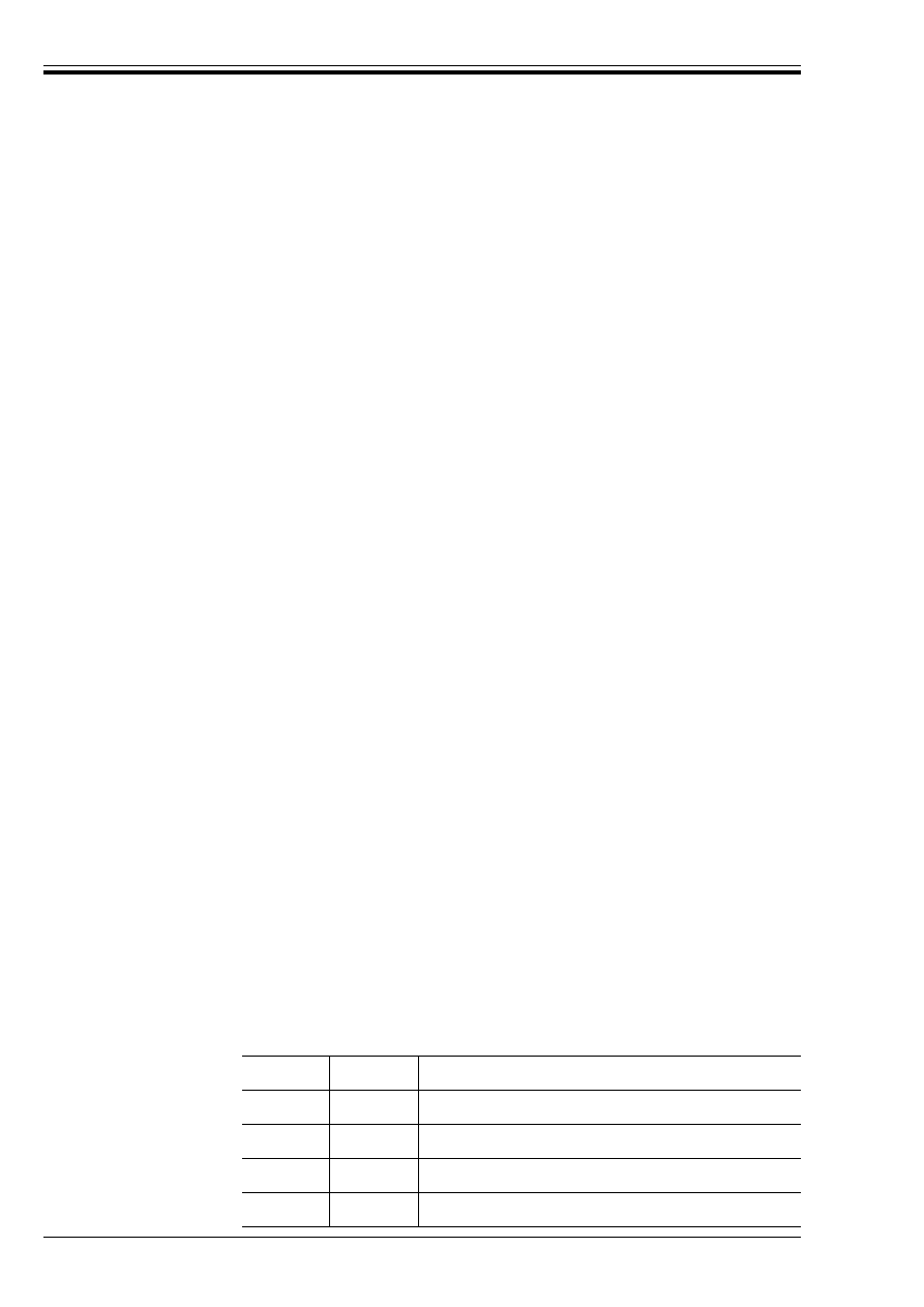
Table 1 — Partial safety factors (¾ factors)
Table 2 — Combination factors (Ó factors)
Reference
in EC5-1.1
Definition
Symbol
Condition
Value
Boxed EC5
UK
2.3.3.1
Partial factors for variable
actions
¾
A
¾
F
,inf
¾
Q
¾
Q
¾
Q
Accidental
Favourable
Unfavourable
Reduced favourable
Reduced unfavourable
1,00
0,0
1,5
0,0
1,35
1,00
0,0
1,5
0,0
1,35
2.3.3.1
Partial factors for
permanent actions
¾
GA
¾
G
¾
G
¾
G
,inf
¾
G
,sup
¾
G
¾
G
Accidental
Favourable
Unfavourable
Favourable
Unfavourable
Reduced favourable
Reduced unfavourable
1,0
1,0
1,35
0,9
1,1
1,0
1,2
1,0
1,0
1,35
0,9
1,1
1,0
1,2
2.3.3.2
Partial factors for materials ¾
M
¾
M
¾
M
¾
M
Timber and wood based materials
Steel used in joints
Accidental
Serviceability
1,3
1,1
1,0
1,0
1,3
1,1
1,0
1,0
Variable action
Building type
Ó
0
Ó
1
Ó
2
Imposed floor loads
Dwellings
0,5
0,4
0,2
Other occupancy classes
a
0,7
0,6
0,3
Parking
0,7
0,7
0,6
Imposed ceiling loads
Dwellings
0,5
0,4
0,2
Other occupancy classes
a
0,7
0,2
0,0
Imposed roof loads
Wind loads
All occupancy classes
a
0,7
0,2
0,0
a
As listed and defined in Table 1 of BS 6399-1:1984.

DD ENV 1995-1-1:1994
© BSI 02-2000
vii
Table 3 — Boxed values (other than ¾ values)
4 Loading codes
The loading codes to be used are:
BS 648, Schedule of weights of building materials.
BS 6399, Design loading for buildings.
BS 6399-1, Code of practice for dead and imposed loads.
BS 6399-3, Code of practice for imposed roof loads.
CP 3, Code of basic data for the design of buildings.
CP 3:Chapter V, Loading.
CP 3:Chapter V-2, Wind loads.
In using these documents with EC5-1.1 the following modifications should be noted:
a) Loads from separate sources or of different durations acting on a member or component should be
considered as separate actions.
b) The design loading on a particular member or component may include the relevant load combination
factors described in 2.3.2.2 and 4.1 of EC5-1.1. Alternatively for the ultimate limit state the
simplification of design load given in 2.3.3.1(5) of EC5-1.1 may be used. For deformations a
simplification is given in 6.4 b) of this NAD.
c) The reductions in total imposed floor load described in clause 5 of BS 6399-1:1984 should be
disregarded.
d) Snow loads arising from local drifting should be treated as an accidental loading condition with the
local drift being the accidental action A
d
, in equation (2.3.2.2b) of EC5-1.1, and the duration of this
accidental loading being short term.
e) The wind loading should be taken as 90 % of the value obtained from CP 3:Chapter V-2.
5 Reference standards
The supporting standards to be used, including materials specifications and standards for construction, are
listed in Table 4.
Reference in
EC5-1.1
Definition
Value
Boxed EC5
UK
a
4.3.1
(2)
Deflections
General u
2,inst
For cantilever u
2,inst
k l/300
k l/150
k l/300
k l/150
4.3.1
(3)
General u
2,fin
For cantilever u
2,fin
General u
net,fin
For cantilever u
net,fin
k l/200
k l/100
k l/200
k l/100
k l/200
k l/100
k l/200
k l/100
4.4.2
(2)
4.4.3
(2)
Vibrations
From machinery
multiplying factor
Residential floors
equation (4.4.3a)
equation (4.4.3b)
1
1,5
100
1
1,5
100
a
Unlike EC5-1.1, this NAD requires 5-percentile stiffness moduli to be used to calculate deformations for solid timber members
acting alone [see 6.4 a) of this NAD].

DD ENV 1995-1-1:1994
viii
© BSI 02-2000
Table 4 — References in EC5 to other publications
Reference
in EC5
Document
referred to
Document title or subject area
a
Status
UK document
b
2.1
P(2)
—
Requirements on accidental
damage and structural integrity
—
Approved Document A
of the Building
Regulations [1]
2.2.2.2
ENV 1991
Basis of design and actions on
structures
In preparation
BS 648
BS 6399
CP 3
(See clause 4 of this
NAD)
2.3.1
P(4)
—
Testing
—
Section 8 of
BS 5268:1991
BS EN 380
BS EN 595
c
BS 5268-6.1
2.4.2
P(1)
EN 350-2
EN 335-1
EN 335-2
prEN 335-3
prEN 351-1
prEN 460
Durability of wood
Hazard classes of wood
and wood-based products
against biological attack
Preservative treatment
Guide to durability requirements
prEN subject to CEN formal vote
1992
1992
prEN subject to CEN formal vote
prEN subject to CEN formal vote
Published 1994
BS EN 350-2
c
BS EN 335-1
BS EN 335-2
BS EN 335-3
c
BS EN 351-1
c
BS EN 460
Table 2.4.3
ISO 2081
EN 10147
Metallic coatings
1986
1991
BS EN 10147
Table 3.1.7
prEN 312
prEN 300
prEN 622
Particleboards
OSB
Fibreboards
prEN subject to CEN formal vote
prEN subject to CEN enquiry
prEN subject to CEN enquiry
BS EN 312
c
BS EN 300
c
BS EN 622
c
3.2.1
P(3)
prEN 518
Visual grading
prEN subject to CEN formal vote BS EN 518
c
3.2.1
P(4)
prEN 519
Machine grading
prEN subject to CEN formal vote BS EN 519
c
3.2.2
prEN 338
prEN 384
prEN 408
prEN 1193
Strength classes of stuctural timber
Characteristic values
Test methods
Test methods
prEN subject to CEN formal vote
prEN subject to CEN formal vote
prEN subject to CEN formal vote
prEN subject to CEN enquiry
BS EN 338
c
BS EN 384
c
BS EN 408
c
prEN 1193
c
3.2.3
prEN 336
Timber sizes and tolerances
prEN subject to CEN formal vote BS EN 336
c
3.2.5
prEN 385
Finger joints
prEN subject to CEN formal vote BS EN 385
c
3.3.1
prEN 386
Performance and production of
glued laminated timber
prEN subject to CEN formal vote BS EN 386
c
3.3.2
prEN 408
prEN 1193
prEN 1194
Test methods for glued laminated
timber
Test method
Characteristic values
prEN subject to CEN formal vote
prEN subject to CEN enquiry
prEN subject to CEN enquiry
BS EN 408
c
BS EN 1193
c
BS EN 1194
c
3.3.3
prEN 390
Sizes of glued laminated timber
prEN subject to CEN formal vote BS EN 390
c
3.3.5
prEN 387
Performance and production of
large finger joints
prEN subject to CEN formal vote BS EN 387
c
3.4.1
prEN 636-1
prEN 636-2
prEN 636-3
prEN 1058
Plywood
Characteristic values of wood-based
panels
prENs subject to CEN enquiry
BS EN 636-1
c
BS EN 636-2
c
BS EN 636-3
c
BS EN 1058
c
ITD/1 [2]
a
See 1.7 of EC5-1.1 for titles of European Standards, published and in preparation.
b
For titles of published UK documents see the list of references to this NAD.
c
British Standard in preparation.

DD ENV 1995-1-1:1994
© BSI 02-2000
ix
Table 4 — References in EC5 to other publications
6 Additional recommendations
6.1 Guidance on EC5-1.1
When designing to EC5-1.1, 6.2 to 6.7 should be followed.
6.2 Chapter 2. Basis of design
a) Clause 2.1P(2)
The design requirements for providing structural integrity by limiting the effects of accidental damage
are given in sections 5 and 6 of Approved Document A 1992 of the Building Regulations 1991 [1].
a) Clause 2.3.1P(4)
ENV 1991-1 (EC1-1.1) Basis of design is currently being drafted to give guidance on the structural
testing and evaluation procedures to be used when the design information in Eurocodes 2 to 9 is
insufficient, or where economies may result from tests on prototypes.
Until the above document is available, prototype testing of assemblies should be carried out to the
standards listed below, and the results assessed in accordance with the requirements of section 8 of
BS 5268-3:1985 for trussed rafters and section 8 of BS 5268-2:1991 for other assemblies, modified as
follows.
NOTE For the design and testing of timber frame wall panels, see 6.5 d) of this NAD.
Reference
in EC5
Document
referred to
Document title or subject area
a
Status
UK document
b
3.4.2
prEN 312-4
prEN 312-5
prEN 312-6
prEN 312-7
prEN 300
prEN 1058
Particleboards
OSB
Characteristic values of wood-based
panels
prENs subject to CEN enquiry
BS EN 312
c
BS EN 300
c
BS EN 1058
c
ITD/2 [3]
3.4.3
prEN 622-3
prEN 622-5
prEN 1058
Fibreboards
Characteristic values of wood-based
panels
prENs subject to CEN enquiry
BS EN 622
c
BS EN 1058
c
ITD/2 [3]
3.5
EN 301
Adhesives
1992
BS EN 301
4.1
(3)
EN 26891
Strength and deformation of joints
made with mechanical fasteners
1991
BS EN 26891
Table 4.1
prEN 312-1
prEN 300
prEN 622-1
Particleboards
OSB
Fibreboards
prEN subject to CEN formal vote
prEN subject to CEN enquiry
prEN subject to CEN enquiry
BS EN 312
c
BS EN 300
c
BS EN 622-1
c
4.4.2
ISO 2631-2
Vibration
1989
5.4.3
prEN 594
Design and testing of wall panels
prEN subject to CEN enquiry
BS 5268-6.1
6.1
P(1)
EN 26891
EN 28970
Strength and deformation of joints
made with mechanical fasteners
Test methods
1991
1991
BS EN 26891
BS EN 28970
7.9.1
7.9.2
(2)
prEN 1059
Trusses
prEN subject to CEN enquiry
—
D.2
(3)
EN 26891
Strength and deformation of joints
made with mechanical fasteners
1991
BS EN 26891
D.6.3
1)
D.6.4
prEN 1075
Test methods for joints made from
punched metal plates
No draft
a
See 1.7 of EC5-1.1 for titles of European Standards, published and in preparation.
b
For titles of published UK documents see the list of references to this NAD.
c
British Standard in preparation.

DD ENV 1995-1-1:1994
x
© BSI 02-2000©
Tests should be carried out to:
BS EN 380 for general structural components;
BS EN 595
1)
for trussed rafters.
The worst loading condition, referred to as the design load, should be determined without the use of the ¾
F
and Ó factors.
For trussed rafters the acceptance load should be assessed in accordance with 39.3 of BS 5268-3:1985
except that the value for K
t
should be taken from Table 5 of this NAD assuming loads are long term. For
other assemblies the acceptance load should be determined by multiplying the design load by the relevant
factor from Table 5. The material categories are those given in Table 3.1.7 of EC5-1.1, i.e.
Where actions of different durations act in combination, the shortest duration of the actions may be used
to determine a factor from Table 5, provided its induced stress is at least 50 % of the total.
For trussed rafters the permissible deflections should be assessed in accordance with 39.2 of
BS 5268-3:1985. For other multiple member components the permissible deflections for a prototype test
should be assessed as given in clause 62 of BS 5268-2:1991, but the following should be noted.
— The “specified amount of deflection in the design” should be calculated as the instantaneous
deflection (u
inst
) in EC5-1.1.
— The definitions of duration of load for determining K
72
and K
80
should be those given in BS 5268-2.
For example, if a load is to simulate a snow load, then the factor (K
72
or K
80
) would be determined for
medium term as given in BS 5268-2, and not short term as given in EC5-1.1.
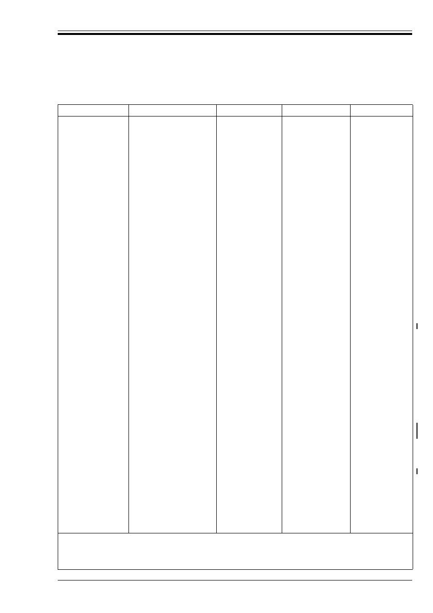
Table 5 — Factors for testing
1)
In preparation.
Category 1
Solid and glued laminated timber and plywood
Category 2
Particleboards to BS EN 312-6
ab
and BS EN 312-7
a
OSB to BS EN 300
a
Grades 3 and 4
Category 3
Particleboards to BS EN 312-4
ab
and BS EN 312-5
a
OSB to BS EN 300
a
Grade 2
Fibreboards to BS EN 622-5
a
(hardboard)
Category 4
Fibreboards to BS EN 622-3
a
(medium boards and hardboards)
a
In preparation.
b
Not to be used in service class 2.
Service duration of actions
or combination of actions
Number tested
Material category
1
2
3
4
Long term
1
2
3
4
5 or more
2,50
2,29
2,16
2,05
2,00
3,50
3,21
3,02
2,87
2,80
3,84
3,53
3,32
3,17
3,07
4,28
3,94
3,70
3,52
3,42
Medium term
1
2
3
4
5 or more
2,18
2,01
1,89
1,80
1,74
2,50
2,29
2,16
2,05
2,00
2,66
2,45
2,30
2,19
2,13
2,58
2,62
2,47
2,35
2,28
Short term
1
2
3
4
5 or more
1,94
1,79
1,68
1,60
1,56
2.03
1,88
1,75
1,68
1,62
2,14
1,96
1,84
1,77
1,71
Instantaneous
1
2
3
4
5 or more
1,59
1,46
1,37
1,30
1,27

DD ENV 1995-1-1:1994
© BSI 02-2000
xi
6.3 Chapter 3. Material properties
a) Clause 3.1.5
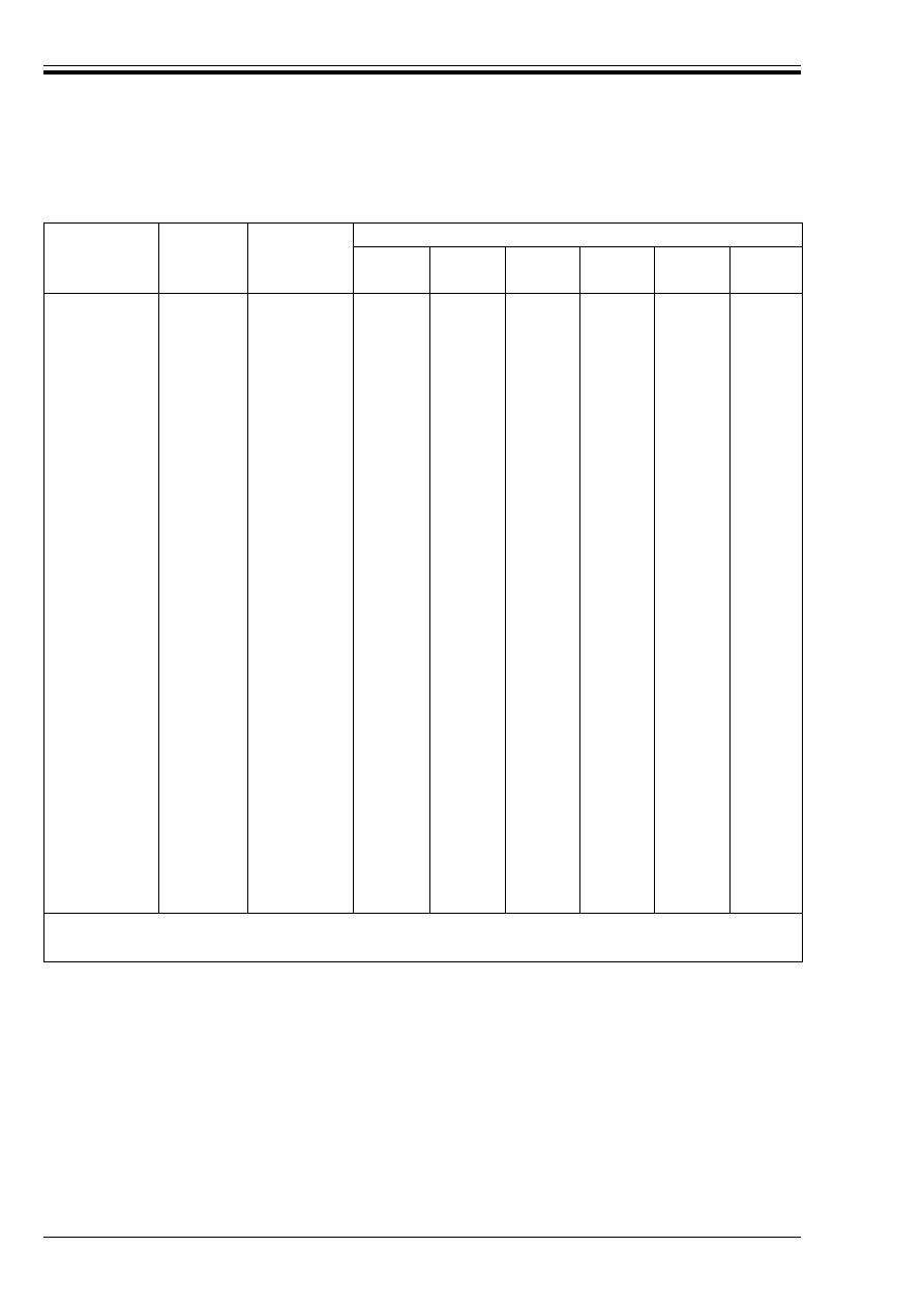
The examples in Table 6 indicate the appropriate service class.
Table 6 — Examples of appropriate service class
b) Clause 3.1.6P(2)
The load duration class is not only determined by the estimated duration of the characteristic load but
also, to a lesser extent, by the duration of loads lower than the characteristic value. In view of the
difficulty of assessing the appropriate duration without specialist knowledge, the examples given in
EC5-1.1 should be used for design in the UK, with the following additional information.
1) Imposed roof loads, where access is limited to maintenance and repair, should be considered as
short term actions.
2) Imposed roof loads, other than snow loads, where access is not limited should be considered as
medium term actions.
3) Uniformly distributed imposed loads on ceilings should be considered as long term actions.
c) Table 3.1.7
Because it is difficult to dry timber more than 100 mm thick, unless it is specially dried, the stresses
and moduli for service class 3 should normally be used for solid timber members more than 100 mm
thick.
d) Clause 3.2.1
Visual and machine strength grading should be carried out under the control of a third party
certification body, authorized by the UK Timber Grading Committee. Only structural timber carrying
the mark of a certification body approved by the UK Timber Grading Committee should be used
(see Annex A).
e) Clause 3.2.2
Characteristic values should be obtained from the strength classes given in BS EN 338
2)
.
If characteristic values are developed for use outside the strength class system, they should be assessed
by the British Standards Institution working group, B525/5/WG1, and the grading quality control and
certification should be assessed by the UK Timber Grading Committee.
Machine grading is carried out directly to the strength class boundaries and the timber is marked
accordingly with a strength class number. Species which can be machine graded, and the strength
classes to which they are assigned, are given in Table 7, Table 8 and Table 9.
Table 7, Table 8 and Table 9 also give the strength classes to which various visual grades and species
are assigned.
f) Clause 3.2.2P(3)
No size adjustments to tension perpendicular to grain and shear stresses are applicable for solid
timber.
g) Clause 3.2.3
Timber sizes normally available in the UK are given in the National annex to BS EN 336
2)
.
Service class
Environmental conditions
1
Timber in buildings with heating and protected from damp conditions. Examples are
internal walls, internal floors (other than ground floors) and warm roofs.
2
Timber in covered buildings. Examples are ground floor structures where no free moisture
is present, cold roofs, the inner leaf of cavity walls and external single leaf walls with
external cladding.
3
Timber fully exposed to the weather. Examples are the exposed parts of open buildings and
timber used in marine structures.
2)
In preparation.

DD ENV 1995-1-1:1994
xii
© BSI 02-2000
Although BS 4978 does not permit cross-section sizes less than 35 mm × 60 mm to be stress graded,
research now shows that sizes down to and including 35 mm × 45 mm may be graded to BS 4978 and
are acceptable for use with the design rules of EC5-1.1 and the strength properties of BS EN 338
3)
.
In common with BS 5268-2, the S8 and S6 grades, specified in the ECE standard on sawn timber [6],
are interchangeable with the SS and GS grades, respectively, of BS 4978.
NOTE The grading rules for the two standards mentioned above differ for square cross sections. The ECE rules for square sizes
are equally acceptable in terms of strength properties and give higher yields.
h) Clause 3.2.5
For EC5-1.1, finger joints to any required specification should be manufactured and tested to
BS EN 385
3)
to determine their characteristic strength. This is different from the system used in
BS 5268-2, where a table relates grades to efficiencies, and in BS 5291 which relates efficiencies to joint
specification.
It is essential that finger joints in principal members, as defined in BS 5268-2, have third party quality
assurance by a certification body approved by the National Accreditation Council of Certification
Bodies (NACCB).
i) Clause 3.3.2(2)
The glulam strength class system given in prEN 1194 makes use of laminates from the solid timber
strength class system given in BS EN 338
3)
.
j) Clause 3.3.2P(3)
The definition of width in tension is the largest cross-sectional dimension, which for glulam is usually
the summation of the laminate thicknesses.
k) Clause 3.2.5
It is essential that large finger joints have third party quality assurance by a certification body
approved by the NACCB.
l) Clause 3.4.1.2
Until the European standard with characteristic values for plywood is published, values converted from
BS 5268-2 and given in ITD/1 [2] should be used.
m) Clause 3.4.2.2
Until the European standard with characteristic values for particleboards is published, values for
structural grade chipboard should be obtained from ITD/2 [3].
n) Clause 3.4.3.2
Until the European standard with characteristic values for fibreboards is published, values converted
from the grade values in BS 5268-2 may be used for tempered hardboard. These should be obtained
from ITD/2 [3].
3)
In preparation.
DD ENV 1995-1-1:1994
© BSI 02-2000
xiii
Table 7 — BS 4978 and NLGA
a
NGRDL
b
joist and plank visual grades and species and CEN
machine grades assigned to strength classes
Type
Species
Source
Grade
c
Strength class
Imported softwoods
British grown softwoods
Redwood
Whitewood
Hem-fir, S-P-F and DF-L
Sitka spruce
Southern pine
Western white woods
Western red cedar
Parana pine
Pitch pine
Radiata pine
Radiata pine
S. African pine
Zimbabwian pine
Spruce
Pine
Larch
Douglas fir
Europe
Europe
Canada and USA
Canada
USA
USA
Imported
Imported
Caribbean
New Zealand
Chile
S. Africa
Zimbabwi
UK and Ireland
SS
GS
Machine
SS
GS
Machine
SS
GS
Machine
JP Sel
JP No. 1
JP No. 2
SS
GS
JP Sel
JP No. 1
JP No. 2
SS
GS
Machine
JP Sel
JP No.1
JP No. 2
JP No. 3
d
SS
GS
JP Sel
JP No. 1
JP No. 2
SS
GS
SS
GS
SS
GS
Machine
Machine
Machine
Machine
SS
Machine
SS
GS
Machine
SS
GS
Machine
SS
GS
Machine
C24
C16
C14 to C30
C24
C16
C14 to C30
C24
C16
C14 to C30
C24
C16
C16
C18
C14
C18
C14
C14
C24
C18
C14 to C30
C30
C22
C22
C16
C18
C14
C18
C14
C14
C18
C14
C24
C16
C27
C18
C14 to C30
C14 to C30
C14 to C30
C14 to C30
C18
C14 to C24
C22
C14
C14 to C27
C24
C16
C14 to C27
C18
C14
C14 to C24
a
National Lumber Grades Authority (Canada)
b
National Grading Rules for Dimension Lumber (USA).
c
Grades are from the following: SS and GS from BS 4978, JP from Standard grading rules for Canadian lumber
[4] and The
national grading rules for dimensioned lumber
[5] and machine grades from EN 519 (in preparation).
d
Joist and plank grade No. 3 should not be used for tension members.
DD ENV 1995-1-1:1994
xiv
© BSI 02-2000
Table 8 — NLGA
a
/NGRDL
b
structural light framing, light framing and stud grades assigned to
strength classes
Species
Source
Grade
Section size
(mm)
38 × 89
38 × 38
38 × 63
63 × 63
63 × 89
38 ×114
89 × 89
38 × 140
DF-L
Hem-fir
S-P-F
Sitka spruce
Western white
woods
Southern pine
Canada
and USA
Canada
and USA
Canada
and USA
Canada
USA
USA
SLF Sel
SLF No. 1
SLF No. 2
SLF No. 3
c
LF Const
c
Stud
c
SLF Sel
SLF No. 1
SLF No. 2
SLF No. 3
c
LF Const
c
Stud
c
SLF Sel
SLF No. 1
SLF No. 2
SLF No. 3
c
LF Const
c
Stud
c
SLF Sel
SLF No. 1
SLF No. 2
SLF Sel
SLF No. 1
SLF No. 2
SLF Sel
SLF No. 1
SLF No. 2
SLF No. 3
c
LF Const
c
LF Std
c
Stud
c
C24
C16
C16
C14
C14
C24
C16
C16
C14
C14
C24
C16
C16
C14
C14
C16
C14
C14
C16
C14
C14
C27
C22
C22
C16
C18
C14
C16
C24
C18
C18
C14
C14
C24
C18
C18
C14
C14
C24
C18
C18
C14
C14
C18
C14
C14
C18
C14
C14
C30
C24
C24
C18
C16
C18
C24
C18
C18
C14
C14
C24
C18
C18
C14
C14
C24
C18
C18
C14
C14
C18
C14
C14
C18
C14
C14
C27
C24
C24
C16
C14
C14
C16
C24
C14
C14
C24
C14
C14
C24
C14
C14
C18
C18
C27
C18
C14
C14
C16
C24
C14
C24
C14
C24
C14
C18
C18
C24
C18
C14
C16
C16
a
National Lumber Grades Authority (Canada).
b
National Grading Rules for Dimension Lumber (USA).
c
Should not be used for tension members.
DD ENV 1995-1-1:1994
© BSI 02-2000
xv
Table 9 — Hardwood grades and species assigned to strength classes
6.4 Chapter 4. Serviceability limit states
a) Clause 4.1(3)
Instantaneous deformation is defined as deformation without creep.
The instantaneous deformation of a solid timber member acting alone should be calculated using the
appropriate 5-percentile modulus of elasticity (E
0,05
) and/or 5-percentile shear modulus (G
0,05
). Where
two or more pieces of solid timber are joined together to act as a single member, the mean values of the
elastic modulii may be used.
For solid timber, G
0,05
= 0,063E
0,05
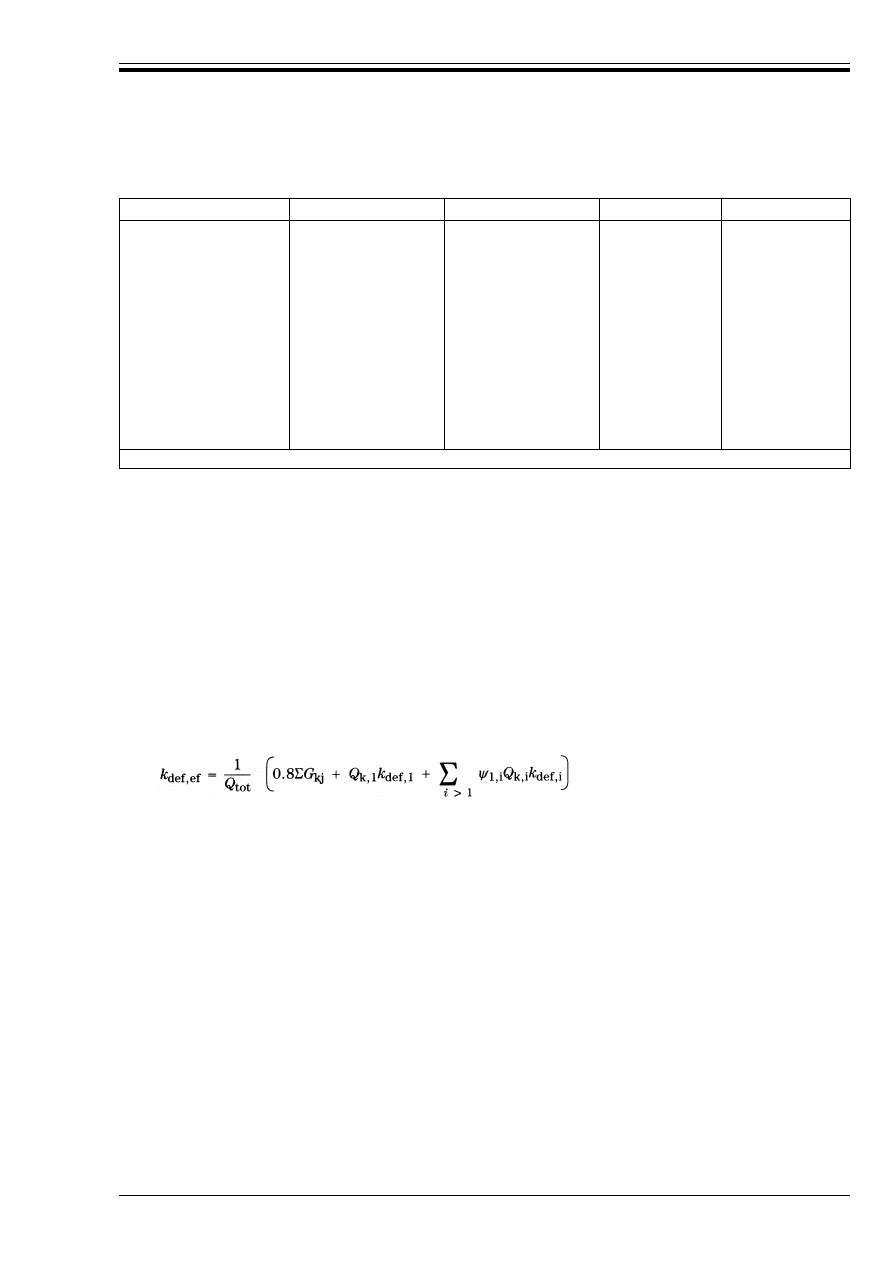
b) Clause 4.1(6)
Where a combination of actions with different load durations occurs on an element or structure, and
when all such actions are uniformly distributed, the final deformation of that element or structure may
be estimated directly under the combined action by using an effective k
def
in equation (4.1b) of EC5-1.1
as follows: The design
where
c) Clause 4.2
The values of K
ser
assume that holes in steel members have the minimum clearance compatible with
the dowel-type fastener to be used (see 7.4 of EC5-1.1).
d) Clause 4.2(3) and 4.2(5)
The value of 1 mm incorporated in equations (4.2d) and (4.2e) of EC5-1.1 is to allow for the clearance
hole for a bolt.
e) Clause 4.4.1
The requirements in this clause are not appropriate to normal UK floors, which are not fully supported
on all four sides and do not have significant transverse stiffness. See 6.4 f) of this NAD.
Type
Species
Source
Grade
a
Strength class
Tropical hardwoods
Kapur
Kempas
Keruing
Ekki
Balau
Greenheart
Iroko
Jarrah
Karri
Merbau
Opepe
Teak
SE Asia
SE Asia
SE Asia
W Africa
SE Asia
SE Asia
Africa
Australia
Australia
SE Asia
Africa
SE Asia and Africa
HS
HS
HS
HS
HS
HS
HS
HS
HS
HS
HS
HS
D60
D60
D50
D60
D70
D70
D40
D40
D50
D60
D50
D40
a
Grades are from BS 5756.
k
def,ef
is the effective deformation factor for the element or structure being considered under
combined action Q
tot
;
Q
tot
is the combined action calculated from equation (4.1a) of EC5-1.1;
k
def,i
is the deformation factor from Table 4.1 of EC5-1.1 appropriate to the duration of action Q
k,i
.
DD ENV 1995-1-1:1994
xvi
© BSI 02-2000
f) Clause 4.4.3
For type 1 residential UK timber floors as defined in Table 1 of BS 6399-1, which are primarily
supported on two sides only and do not have significant transverse stiffness, it is sufficient to check
that the total instantaneous deflection of the floor joists under load does not exceed 14 mm or l/333,
whichever is the lesser.
6.5 Chapter 5. Ultimate limit states
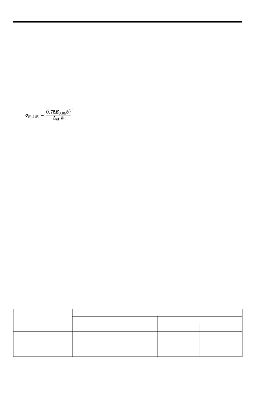
a) Clause 5.2.2
The value B
m.crit
for rectangular sections can be obtained from the following equation:
The effective value of L
ef
is governed by the degree of restraint against:
1) lateral deflection;
2) rotation in plan; and
3) twisting.
As a guide:
— where full restraint is provided against rotation in plan at both ends, L
ef
= 0,7L;
— where partial restraint against rotation in plan is provided at both ends or full restraint at one end,
L
ef
= 0,85L;
— where partial restraint against twisting is provided at one or both ends, L
ef
= 1,2L.
b) Clause 5.4.1.4P(4)
For the purposes of lateral stability calculations on rafter members, the effective length for out-of-plane
buckling should be taken as the distance between discrete restraints, provided these are adequately
fixed to the member and anchored to a braced part of the structure.
c) Clause 5.4.1.5(1)
Irrespective of any other design requirements, the maximum bay length of trussed rafter chord
members, when measured on plan between node points, should be limited to the values given in
Table 10 and the maximum overall length of internal members should be limited to the values given in
Table 11.
Where necessary, intermediate values may be obtained by linear interpolation.
d) Clause 5.4.3
The design method for timber frame walls given in EC5-1.1 lacks sufficient information with regard to
the determination of racking resistance (F
k
) from the test method. This NAD will be revised in due
course to give the required additional information. Until that revision is published, timber frame wall
panels should be designed and tested to BS 5268-6.1.
6.6 Chapter 6. Joints
a) Clause 6.1
Glued joints should be designed taking into consideration the strength properties of the timber and/or
wood-based members to be joined, which are assumed to be weaker than the glue.
Table 10 — Maximum bay length of rafters and ceiling ties
Depth of member
(mm)
Maximum length (measured on plan between node points)
(m)
35 mm thick
47 mm thick
Rafter
Ceiling tie
Rafter
Ceiling tie
72
97
122
147
1,8
2,3
2,5
2,8
2,4
3,0
3,4
3,7
3,0
3,3
3,6
3,8
3,0
4,0
4,7
5,0

DD ENV 1995-1-1:1994
© BSI 02-2000
xvii
Table 11 — Maximum length of internal members
b) Clause 6.1(9)
The ultimate limit state slip modulus K
u
is applicable in ultimate limit state calculations where the
influence of fastener slip on strength needs to be considered. Joint slip should be calculated by dividing
the applied design load per fastener (at either service load or ultimate load level) by the appropriate
fastener slip modulus.
c) Clause 6.2.1
The formulae for R
d
provide characteristic design resistances for the ultimate limit state. They should
not be used to establish design resistances at the service load level.
Connectored joints
Until prEN 912 (the specification for connectors for timber), a standard for characteristic load carrying
capacities and slip moduli for connectors, and a design method for connectored joints are available,
characteristic load carrying capacities for connectors should be obtained by multiplying the basic loads
tabulated in BS 5268-2 by a factor of 2,6 for toothed plate connectors and 2,9 for split-ring and shear
plate connectors. The design capacity is given by the following equation:
where
k
mod
and ¾
M
are the values for solid timber and glulam.
The standard spacings and distances given in BS 5268-2 should be used, unless the characteristic
values are reduced by the appropriate factors for substandard spacings and distances, given in
BS 5268-2.
6.6 Annex D. The design of trusses with punched metal plate fasteners
a) Clause D.2
The value of u
ser
can be taken as the average initial slip value published in the appropriate British
Board of Agrément (BBA) certificate.
The value of K
ser
can be obtained from the following equation:
K
ser
= F
a,00,k
× A
ef
/(2,5 × uu
ser
)
b) Clause D.6.2
Unless experience indicates that a larger tolerance is necessary, A
ef
should allow for a minimum
misalignment of 5 mm simultaneously in two directions parallel to the edges of the punched metal
plate fastener. In addition, allowance should be made for any ineffective nails nearer than certain
specified distances from the edges and ends of the timber and published in a British Standard, a BBA
certificate or a certificate of assessment from an accredited body which provides equivalent levels of
protection and performance.
c) Clause D.6.3
Characteristic anchorage capacities for metal plate fasteners should be obtained directly from a
British Standard, a BBA certificate or a certificate of assessment from an accredited body which
provides equivalent levels of protection and performance, by multiplying the permissible long-term
loads per nail by a factor of 2,5 and dividing by the area per nail. Linear interpolation may be used to
obtain intermediate characteristic capacities.
The design anchorage capacity is given by the following equation:
R
d
= k
mod
× characteristic anchorage capacity/¾
M
Depth of member
(mm)
Maximum length (measured on plan between
node points)
(m)
35 mm thick
47 mm thick
60
72
97
2,4
3,6
4,5
3,2
4,8
6,0
R
d
= k
mod
× characteristic value for connector/
¾
M

DD ENV 1995-1-1:1994
xviii
© BSI 02-2000
where
k
mod
and ¾
M
are the values for solid timber.
Characteristic tension, compression and shear capacities of metal plate fasteners should be obtained by
multiplying the permissible forces published in the appropriate BBA certificate by 2,33. Linear
interpolation may be used to obtain intermediate characteristic capacities.
The design tension, compression and shear capacities of metal plate fasteners are given by the
following equation:
R
d
= k
mod
× characteristic capacity/¾
M
where
k
mod
= 1,0 and ¾
M
= 1,1.

DD ENV 1995-1-1:1994
© BSI 02-2000
xix
Annex A (informative)
Acceptable certification bodies for strength graded timber
Certification bodies currently approved are listed in Table A.1 to Table A.5.
NOTE A leaflet containing an illustration of each grading stamp logo and the address of each certification body
4)
, can be obtained
from the UK Timber Grading Committee, The Timber Trade Federation, Clareville House, 26/27 Oxendon Street, London SW1Y 4EL.
Table A.1 — Certification bodies approved to oversee the supply of visually strength
graded timber to BS 4978
Table A.2 — Certification bodies operating under the Canadian Lumber Standards
Accreditation Board (CLSAB) approved for the supply of visually strength graded timber to the
NLGA grading rules
Table A.3 — Certification bodies operating under the American Lumber Standards Board of
Review (ALS) approved for the supply of visually strength graded timber to the NGRDL
grading rules
4)
Addresses of the UK representative referred to in Table A.1 to Table A.5 are as follows:
Bureau de Promotion des Industries du Bois (BPIB), Unit 3, Blenheim Court, 7 Beaufort Park, Woodlands, Almondsbury, Bristol
BS12 4NE Tel. 0454 616000 Fax 0454 616080
Council of Forest Industries of British Columbia (COFI), Tileman House, 131-133 Upper Richmond Road, London SW15 2TR
Tel. 081 788 4446 Fax 081 789 01480
TRADA Certification Ltd. (TRADACERT), Stocking Lane, Hughenden Valley, High Wycombe, Bucks HP14 4NR Tel. 0494 565484
Fax 0494 565487
BSI Quality Assurance (BSIQA), PO Box 375, Milton Keynes, Bucks MK14 6LL Tel. 0908 220908 Fax 0908 220671
Nordic Timber Council UK (NTC), 17 Exchange Street, Retford, Notts DN22 6BL Tel. 0777 706616 Fax 0777 704695
Southern Pine Marketing Council (SFPA) and Western Wood Products Association (WWPA), 65 London Wall, London EC2M 5TU
Certification body
UK representative
Certification body
UK representative
AFPA
CLA
CLMA
COFI
ILMA
MI
MLB
OLMA
PLIB (Can)
PLIB (USA)
COFI
BPIB
COFI
COFI
COFI
COFI
BPIB
BPIB
COFI
WWPA
QLMA
SPIB
SGMCF
SSTCC
TRADACERT
WCLIB
WWPA
BPIB
WWPA/SFPA
NTC
NTC
TRADACERT
MI
WWPA
Certification body
UK representative
Certification body
UK representative
AFPA
CLA
CLMA
COFI
ILMA
MI
COFI
BPIB
COFI
COFI
COFI
COFI
MLB
NLPA
OLMA
PLIB (Can)
QLMA
BPIB
BPIB
BPIB
COFI
BPIB
Certification body
UK representative
Certification body
UK representative
PLIB (USA)
SPIB
TPI
WWPA
WWPA/SFPA
WWPA/SFPA
WCLIB
WWPA
WWPA
WWPA

DD ENV 1995-1-1:1994
xx
© BSI 02-2000
Table A.4 — Certification bodies approved to
oversee the supply of machine strength
graded timber to BS EN 519
a
(both machine control and
output control systems)
Table A.5 — Certification bodies approved to oversee the supply of machine strength graded
timber to BS EN 519
a
(output control system only)
Certification body
UK representative
BSIQA
TRADACERT
BSIQA
TRADACERT
a
In preparation.
Certification body
UK representative
Certification body
UK representative
AFPA
CLMA
COFI
ILMA
MI
PLIB (Can)
COFI
COFI
COFI
COFI
COFI
COFI
SPIB
TPI
WCLIB
WWPA
QLMA
WWPA/SFPA
WWPA/SFPA
WWPA
WWPA
BPIB
a
In preparation.

DD ENV 1995-1-1:1994
© BSI 02-2000
xxi
List of references
(see clause 2)
Normative references
BSI publications
BRITISH STANDARDS INSTITUTION, London
BS 648:1964, Schedule of weights of building materials.
BS 5268, Structural use of timber.
BS 5268-2:1991, Code of practice for permissible stress design, materials and workmanship.
BS 5268-3:1985, Code of practice for trussed rafter roofs.
BS 5268-6, Code of practice for timber frame walls.
BS 5268.6.1:1988, Dwellings not exceeding three storeys.
BS 6399, Design loading for buildings.
BS 6399-1:1984, Code of practice for dead and imposed loads.
BS 6399-3:1988, Code of practice for imposed roof loads.
CP 3, Code of basic data for the design of buildings.
CP 3:Chapter V, Loading.
CP 3:Chapter V-2:1972, Wind loads.
BS EN 301:1992, Adhesives, phenolic and aminoplastic, for load-bearing timber structures: classification
and performance requirements.
BS EN 335, Hazard classes of wood and wood-based products against biological attack.
BS EN 335-1:1992, Classification of hazard classes.
BS EN 335-2:1992, Guide to the application of hazard classes to solid wood.
BS EN 380:1993, Timber structures — Test methods — General principles for static load testing.
BS EN 460:1994, Durability of wood and wood-based products — Natural durability of wood — Guide to
the durability requirements to be used in hazard classes.
BS EN 10147:1992, Specification for continuously hot-dip zinc coated structural steel sheet and strip —
Technical delivery conditions.
BS EN 26891:1991, Timber structures — Joints made with mechanical fasteners — General principles for
the determination of strength and deformation characteristics.
BS EN 28970:1991, Timber structures — Testing of joints made with mechanical fasteners — Requirements
for wood density.
ISO publications
INTERNATIONAL ORGANIZATION FOR STANDARDIZATION (ISO), GENEVA. (All publications are available from BSI Sales.)
ISO 2081:1986, Metallic coatings — Electroplated coatings of zinc on iron or steel.
ISO 2631, Evaluation of human exposure to whole-body vibration.
ISO 2631-2:1989, Part 2: Continuous and shock-induced vibrations in buildings (1 to 80 Hz).
Other references
[2] TIMBER RESEARCH AND DEVELOPMENT ASSOCIATION. Plywood properties for use with
Eurocode 5: Interim technical data sheet ITD
/1. London: TRADA, 1993
5)
.
[3] TIMBER RESEARCH AND DEVELOPMENT ASSOCIATION. Structural chipboard and tempered
hardboard properties for use with Eurocode 5: Interim technical data sheet ITD
/2. London: TRADA, 1993
5)
.
5)
Available from TRADA, Stocking Lane, Hughenden Valley, High Wycombe, Bucks HP14 4NR.

DD ENV 1995-1-1:1994
xxii
© BSI 02-2000
Informative references
BSI publications
BRITISH STANDARDS INSTITUTION, London
BS 4978:1988, Specification for softwood grades for structural use.
BS 5291:1984, Specification for manufacture of finger joints of structural softwood.
BS 5756:1980, Specification for tropical hardwoods graded for structural use.
Other references
[1] GREAT BRITAIN. The Building Regulations 1991, Approved Document A 1992 Requirements on
accidental damage and structural integrity.
London: HMSO.
[4] NATIONAL LUMBER GRADES AUTHORITY. Standard grading rules for Canadian lumber.
Vancouver: NLGA, 1993
6)7)
.
[5] NATIONAL GRADING RULES FOR DIMENSIONED LUMBER. The national grading rules for
dimensioned lumber.
NGRDL, 1993
8)
.
[6] ECONOMIC COMMITTEE FOR EUROPE (ECE). Sawn timber: Recommended standard for stress
grading of coniferous sawn timber.
Geneva: ECE, 1982.
6)
The relevant section of the rules is Section 4 which is technically equivalent to the National Grading Rules for Dimensioned
Lumber [5].
7)
Available from: Council of The Forest Industries of British Columbia, Tileman House, 131-133 Upper Richmond Road, London
SW15 2TR.
8)
Available from: Southern Pine Marketing Council and Western Wood Products Association, 65 London Wall, London
EC2M 5TU.

EUROPEAN STANDARD
NORME EUROPÉENNE
EUROPÄISCHE NORM
ENV 1995-1-1
December 1993
UDC 624.92.016.02:624.07
Incorporates corrigendum 1994
Descriptors: Buildings, timber structures, computations, building codes, rules of calculation
English version
Eurocode 5 — Design of timber structures —
Part 1.1: General rules and rules for buildings
Eurocode 5 — Calcul des structures en bois —
Partie 1.1: Régles générales et règles pour les
bâtiments
Eurocode 5 — Entwurf, Berechnung und
Bemessung von Holzbauwerken —
Teil 1.1: Allgemeine
Bemessungsregelnwerken, Bemessungsregeln
für den Hochbau
This European Prestandard (ENV) was approved by CEN on 1992-11-20 as a
prospective standard for provisional application. The period of validity of this
ENV is limited initially to three years. After two years the members of CEN
will be requested to submit their comments, particularly on the question
whether the ENV can be converted into a European Standard (EN).
CEN members are required to announce the existence of this ENV in the same
way as for an EN and to make the ENV available promptly at national level in
an appropriate form. It is permissible to keep conflicting national standards in
force (in parallel to the ENV) until the final decision about the possible
conversion of the ENV into an EN is reached.
CEN members are the national standards bodies of Austria, Belgium,
Denmark, Finland, France, Germany, Greece, Iceland, Ireland, Italy,
Luxembourg, Netherlands, Norway, Portugal, Spain, Sweden, Switzerland and
United Kingdom.
CEN
European Committee for Standardization
Comité Européen de Normalisation
Europäisches Komitee für Normung
Central Secretariat: rue de Stassart 36, B-1050 Brussels
© 1993 Copyright reserved to CEN members
Ref. No. ENV 1995-1-1:1993 E

ENV 1995-1-1:1993
© BSI 02-2000
2
Foreword
01 Objectives of the Eurocodes
The Eurocodes constitute a group of standards for
the structural and geotechnical design of building
and civil engineering works. They will cover
execution and control to the extent that it is
necessary to indicate the quality of the construction
products and the standard of workmanship needed
on and off-site to comply with the assumptions of the
design rules. While the necessary set of harmonised
technical specifications for products and methods
for testing their performance is not available, the
Eurocodes may cover some of these aspects.
The Eurocodes are intended to serve as reference
documents for the following purposes:
a) as a means to prove compliance of building and
civil engineering works with the essential
requirements of the Construction Products
Directive;
b) as a framework for drawing up harmonized
technical specifications for construction products.
02 Background to the Eurocode programme
The Commission of the European Communities
(CEC) initiated the work of establishing a set of
harmonised technical rules for the design of
building and civil engineering works which would
initially serve as an alternative to the differing rules
in force in the various Member States and,
ultimately would replace them. These technical
rules became known as the “Structural Eurocodes”.
In 1990, after consulting their respective Member
States, CEC and EFTA Secretariat transferred the
work on further development, issue and updating of
Eurocodes to CEN.
In CEN, Technical Committee CEN/TC 250 has
overall responsibility for the Structural Eurocodes.
03 Eurocode programme
Work is in hand on the following Eurocodes each
consisting of a number of parts:
EC 1: Basis of design and actions on structures
EC 2: Design of concrete structures
EC 3: Design of steel structures
EC 4: Design of composite steel and concrete
structures
EC 5: Design of timber structures
EC 7: Geotechnics
EC 8: Design of structures in seismic regions
EC 9: Design of aluminium structures (subject to
Mandate)
For each Eurocode listed above, CEN/TC 250 has
formed a Sub-committee.
This part of Eurocode EC5 which had been finalised
and approved for publication under the direction of
CEC, is being issued by CEN as European
Prestandard (ENV). It is intended for experimental
practical application in the design of building and
civil engineering works covered by the scope of the
Prestandard as given in Clause 1.1.2.
Feedback and comments on this prestandard should
be sent to the Secretariat of Sub-Committee SC5 at
the following address:
SIS
BST
Drottning Kristinas väg 73
S-11428 STOCKHOLM
04 National application documents
In view of the responsibilities of Members of states
for the safety health and other matters covered by
the essential requirements, certain safety elements
in this ENV have been assigned indicative values.
The authorities in each Member state are expected
to assign definitive values to these safety elements.
Many of the supporting standards, including those
giving values for actions to be taken into account
and measures required for fire protection, will not
be available by the time this Prestandard is issued.
It is therefore anticipated that a National
Application Document giving definitive values for
safety elements, referencing compatible supporting
standards and giving national guidance on the
application of this Prestandard will be issued by
each Member State or its Standard Organisation.
This Prestandard should be used in conjunction
with the National Application Document valid in
the country where the building and civil engineering
work is to be constructed.

ENV 1995-1-1:1993
© BSI 02-2000
3
Contents
Page
Foreword
2
1
Introduction
7
1.1
Scope
7
1.1.1
Scope of Eurocode 5
7
1.1.2
Scope of Part 1-1 of Eurocode 5
7
1.1.3
Further parts of Eurocode 5
7
1.2
Distinction between principles and
application rules
7
1.3
Assumptions
8
1.4
Definitions
8
1.4.1
Terms common to all Eurocodes
8
1.4.2
Special terms used in part 1-1
of Eurocode 5
9
1.5
S.I. Units
9
1.6
Symbols used in part of 1
Eurocode 5
9
1.6.1
General
9
1.6.2
Symbol used in chapter 2
9
1.6.3
Symbol used in chapter 3–7
and annexes
10
1.7
References
12
2
Basis of design
13
2.1
Fundamental requirements
13
2.2
Definitions and classifications
14
2.2.1
Limit states and design situations
14
2.2.1.1 Limit States
14
2.2.1.2 Design Situations
14
2.2.2
Actions
14
2.2.2.1 Definitions and principal
classification
14
2.2.2.2 Characteristic values of actions
15
2.2.2.3 Representative values of variable
actions
15
2.2.2.4 Design values of actions
16
2.2.2.5 Design values of the effects of
actions
16
2.2.3
Material properties
16
2.2.3.1 Characteristic values
16
2.2.3.2 Design values
16
2.2.4
Geometrical data
16
2.2.5
Load arrangements and load cases
17
2.3
Design requirements
17
2.3.1
General
17
2.3.2
Ultimate limit states
17
2.3.2.1 Verification conditions
17
Page
2.3.2.2 Combinations of actions
17
2.3.2.3 Design values of permanent
actions
18
2.3.3
Partial safety factors for ultimate
limit state
18
2.3.3.1 Partial safety factors for actions
on building structures
18
2.3.3.2 Partial safety factors for materials
19
2.3.4
Serviceability limit states
20
2.4
Durability
20
2.4.1
General
20
2.4.2
Resistance to biological organisms
20
2.4.3
Resistance to corrosion
20
3
Material properties
21
3.1
General
21
3.1.1
Strength and stiffness parameters
21
3.1.2
Characteristic values
21
3.1.3
Stress-strain relations
21
3.1.4
Calculation models
21
3.1.5
Service classes
21
3.1.6
Load-duration classes
21
3.1.7
Modification factors for moisture
content and duration of load
22
3.2
Solid timber
23
3.2.1
Grading
23
3.2.2
Characteristic strength and
stiffness values and densities
23
3.2.3
Timber sizes
23
3.2.4
Modification factors for service
class and duration of load
23
3.2.5
Finger joints
23
3.3
Glued laminated timber
23
3.3.1
Performance requirements
23
3.3.2
Characteristic strength and
stiffness values
23
3.3.3
Sizes of glued laminated timber
24
3.3.4
Modification factors for service
class and duration of load
24
3.3.5
Large finger joints
24
3.4
Wood-based panels
24
3.4.1
Plywood
24
3.4.1.1 Requirements
24
3.4.1.2 Characteristic strength
and stiffness values
24
3.4.1.3 Modification factors for service
class and duration of load
24
3.4.2
Particleboard
24

ENV 1995-1-1:1993
4
© BSI 02-2000
Page
3.4.2.1 Requirements
24
3.4.2.2 Characteristic strength and
stiffness values
25
3.4.2.3 Modification factors for service
class and duration of load
25
3.4.3
Fibreboard
25
3.4.3.1 Requirements
25
3.4.3.2 Characteristic strength and
stiffness values
25
3.4.3.3 Modification factors for service
class and duration of load
25
3.5
Adhesives
25
4
Serviceability limit states
25
4.1
General requirements
25
4.2
Joint slip
27
4.3
Limiting values of deflection
27
4.3.1
Beams
27
4.3.2
Trusses
28
4.4
Vibrations
28
4.4.1
General
28
4.4.2
Vibrations from machinery
28
4.4.3
Residential floors
28
5
Ultimate limit states
29
5.1
Basic rules
29
5.1.1
General
29
5.1.2
Tension parallel to the grain
29
5.1.3
Tension perpendicular to the
grain
29
5.1.4
Compression parallel to the
grain
29
5.1.5
Compression at an angle to
the grain
29
5.1.6
Bending
30
5.1.7
Shear
31
5.1.7.1 General
31
5.1.7.2 End-notched beams
31
5.1.8
Torsion
32
5.1.9
Combined bending and axial
tension
32
5.1.10 Combined bending and axial
compression
33
5.2
Columns and beams
33
5.2.1
Columns
33
5.2.2
Beams
34
5.2.3
Single tapered beams
34
5.2.4
Double tapered, curved and
pitched cambered beams
35
Page
5.3
Components
38
5.3.1
Glued thin-webbed beams
38
5.3.2
Glued thin-flanged beams
39
5.3.3
Mechanically jointed beams
40
5.3.4
Mechanically jointed and glued
columns
41
5.4
Assemblies
41
5.4.1
Trusses
41
5.4.1.1 General
41
5.4.1.2 General analysis
41
5.4.1.3 Simplified analysis
42
5.4.1.4 Strength verification of
members
42
5.4.1.5 Trusses with punched metal
plate fasteners
43
5.4.2
Roof and floor diaphragms
43
5.4.3
Wall diaphragms
43
5.4.4
Plane frames
45
5.4.5
Bracing
46
5.4.5.1 General
46
5.4.5.2 Single members in compression
46
5.4.5.3 Bracing of beam or truss
systems
47
5.4.6
Load sharing
47
6
Joints
48
6.1
General
48
6.2
Lateral load-carrying capacity
of dowel-type fasteners
49
6.2.1
Timber-to-timber and
panel-to-timber joints
49
6.2.2
Steel-to-timber joints
51
6.2.3
Multiple shear joints
52
6.3
Nailed joints
52
6.3.1
Laterally loaded nails
52
6.3.1.1 General
52
6.3.1.2 Nailed timber-to-timber joints
53
6.3.1.3 Nailed panel-to-timber joints
55
6.3.1.4 Nailed steel-to-timber joints
55
6.3.2
Axially loaded nails
55
6.3.3
Combined laterally and axially
loaded nails
56
6.4
Stapled joints
57
6.5
Bolted joints
57
6.5.1
Laterally loaded bolts
57
6.5.1.1 General
57
6.5.1.2 Bolted timber-to-timber joints
57

ENV 1995-1-1:1993
© BSI 02-2000
5
Page
6.5.1.3 Bolted panel-to-timber joints
57
6.5.1.4 Bolted steel-to-timber joints
58
6.5.2
Axially loaded bolts
58
6.6
Dowelled joints
58
6.7
Screwed joints
58
6.7.1
Laterally loaded screws
58
6.7.2
Axially loaded screws
58
6.7
Combined laterally and axially
loaded screws
58
6.8
Joints made with punched metal
plate fasteners
59
7
Structural detailing and control
59
7.1
General
59
7.2
Materials
59
7.3
Glued joints
59
7.4
Joints with mechanical fasteners
59
7.5
Assembly
60
7.6
Transportation and erection
60
7.7
Control
60
7.7.1
General
57
7.7.2
Production and workmanship
control
60
7.7.3
Controls after completion
of the structure
61
7.8
Special rules for diaphragm
structures
61
7.8.1
Roof and floor diaphragm
structures
61
7.8.2
Wall diaphragms
61
7.9
Special rules for trussed rafters
61
7.9.1
Fabrication
61
7.9.2
Erection
62
Annex A (informative) Determination
of 5-percentile characteristic values
fromtest results and acceptance criteria
for a sample
63
A.1
Scope
63
A.2
Determination of the 5-percentile
characteristic value
63
A.2.1
Requirements
63
A.2.2
Method
63
A.3
Acceptance criteria for a sample
63
A.3.1
Requirements
63
A.3.2
Method
64
Annex B (informative) Mechanically
jointed beams
64
B.1
General
64
Page
B.1.1
Cross sections
64
B.1.2
Structures and assumptions
64
B.1.3
Spacings
64
B.1.4
Deflections resulting from
bending moments
64
B.2
Effective bending stiffness
66
B.3
Normal stresses
66
B.4
Maximum shear stress
66
B.5
Load on fasteners
66
Annex C (informative) Built-up columns
66
C.1
General
66
C.1.1
Assumptions
66
C.1.2
Load-carrying capacity
66
C.2
Mechanically jointed columns
67
C.2.1
Assumptions
67
C.2.2
Effective slenderness ratio
67
C.2.3
Load on fasteners
67
C.2.4
Combined loads
67
C.3
Spaced columns with packs or gussets 67
C.3.1
Assumptions
67
C.3.2
Axial load-carrying capacity
68
C.3.3
Load on fasteners gussets and
packs
69
C.4
Lattice columns with glued or
nailed joints
69
C.4.1
Structures
69
C.4.2
Load-carrying capacity
71
C.4.3
Shear forces
71
Annex D (normative) The design of trusses
with punched metal plate fasteners
72
D.1
General
72
D.2
Joints
72
D.3
General analysis
72
D.4
Simplified analysis
72
D.5
Strength verification of members
73
D.6
Strength verification of punched
metal plate fasteners
73
D.6.1
General
73
D.6.2
Plate geometry
73
D.6.3
Plate strength capacities
74
D.6.4
Anchorage strengths
74
D.6.5
Joint strength verification
75
D.6.5.1 Plate anchorage capacity
75
D.6.5.2 Plate capacity
75
D.6.5.3 Minimum anchorage
requirements
76

ENV 1995-1-1:1993
6
© BSI 02-2000
Page
Figure 4.3.1 — Components of deflection
27
Figure 5.1.5a — Compression perpendicular
to the grain
30
Figure 5.1.5b — Stresses at an angle
to the grain
30
Figure 5.1.6 — Beam axes
31
Figure 5.1.7.1 — Reduced influence line for
point loads
31
Figure 5.1.7.2 (a) and (b) — End-notched
beams
32
Figure 5.2.3 — Single tapered beam
34
Figure 5.2.4 — Double tapered a), curved b)
and pitched cambered c) beams
36
Figure 5.3.1 — Thin-webbed beams
38
Figure 5.3.2 — Thin-flanged beam
40
Figure 5.4.1.1 — Examples of truss
configurations and model elements
41
Figure 5.4.1.4 — Effective column lengths
42
Figure 5.4.2 — Diaphragm loading and
staggered panel arrangements
43
Figure 5.4.3 — Arrangement of a typical
panel a) and a test panel b)
44
Figure 5.4.3c — Assembly of panels
with openings
45
Figure 5.4.4 — Examples of assumed initial
deflections for a frame a), corresponding to
a symmetrical load b) and non-symmetrical
load c)
46
Figure 5.4.5.2 — Examples of single members
in compression braced by lateral supports
47
Figure 5.4.5.3 — Beam or truss system
requiring lateral supports
47
Figure 6.1 — Joint force acting at an angle
to the grain
49
Figure 6.2.1 — Failure modes for timber
and panel joints
51
Figure 6.2.2 a–1 — Failure modes for
steel-to-timber joints
52
Figure 6.3.1 (a) and (b) — Definitions
of t
1
and t
2
53
Figure 6.3.1.2a — Fastener spacings and
distances — definitions
54
Figure 6.3.1.2b — Overlapping nails
54
Figure 6.3.2 (a) and (b) — Perpendicular
and slant nailing
56
Figure 7.8.1 — Examples of connection of
panels not supported by a joist or a rafter.
Sheathing is nailed to battens which are
slant nailed to the joists or rafters
61
Figure 7.8.2 — Panel fixings
61
Page
Figure B.1.1 — Cross-section (left) and
distribution of bending stresses (right)
All measurements are positive except
for a
2
which is taken as positive as shown
65
Figure C.3.1 — Spaced columns
68
Figure C.3.3 — Shear force distribution
and loads on gussets and packs
69
Figure C.4.1 — Lattice columns. The area of
one flange is A
f
and the second moment of
area about its own axis of gravity is I
f
70
Figure D.4 — Rules for a pinned support
73
Figure D.6.2 — Geometry of nail plate
connection loaded by a force F and moment M
74
Table 2.3.2.2 — Design values of actions for
use in the combination of actions
17
Table 2.3.3.1 — Partial safety factors for
actions in building structures for persistent
and transient design situations
19
Table 2.3.3.2 — Partial coefficients for
material properties (*
M
)
19
Table 2.4.3 — Examples of minimum material
or corrosion protection specifications for
fasteners (related to ISO 2081)
20
Table 3.1.6 — Load-duration classes
22
Table 3.1.7 — Values of k
mod
22
Table 4.1 — Values of k
def
for timber,
wood-based materials and joints
26
Table 4.2 — Values of K
ser
for dowel-type
fasteners in N/mm
27
Table 5.1.5 — Values of k
c,90
30
Table 5.3.2 — Maximum effective flange
widths due to the effect of shear lag and
plate buckling
39
Table 5.4.6 — Description of assemblies
and load-distribution systems
48
Table 6.3.1.2 — Minimum nail spacings
and distances — values
55
Table 6.5.1.2 — Minimum spacings and
distances for bolts
57
Table 6.6a — Minimum spacings and
distances for dowels
58
Table A.2 — Factor k
1
63
Table A.3 — Factor k
2
64
Table C.3.2 — The factor )
69

ENV 1995-1-1:1993
© BSI 02-2000
7
1 Introduction
1.1 Scope
1.1.1 Scope of Eurocode 5
P(1) Eurocode 5 applies to the design of timber structures — i.e., structures made of timber (solid timber,
sawn, planed or in pole form, and glued laminated timber) or wood-based panels jointed together with
adhesives or mechanical fasteners. It is subdivided into various separate parts, see 1.1.2 and 1.1.3.
P(2) Eurocode 5 is only concerned with the requirements for mechanical resistance, serviceability and
durability of structures. Other requirements, e.g. concerning thermal or sound insulation, are not
considered.
P(3) Execution
9)
is covered to the extent that is necessary to indicate the quality of the construction
materials and products which should be used and the standard of workmanship on site needed to comply
with the assumptions of the design rules. Execution and workmanship are covered in Chapter 7, and are
to be considered as minimum requirements which may have to be further developed for particular types of
buildings and methods of construction
9)
.
P(4) Eurocode 5 does not cover the special requirements of seismic design. Provisions related to such
requirements are given in Eurocode 8 “Design of Structures in Seismic Regions”
10)
which complements
Eurocode 5.
P(5) Numerical values of the actions on buildings and civil engineering works to be taken into account in
the design are not given in Eurocode 5. They are provided in Eurocode 1 “Basis of design and actions on
structures
”
10)
.
1.1.2 Scope of part 1-1 of Eurocode 5
P(1) Part 1-1 of Eurocode 5 gives a general basis for the design of buildings and civil engineering works.
P(2) In addition, Part 1-1 gives detailed rules which are mainly applicable to ordinary structures. The
applicability of these rules may be limited for practical reasons or due to simplifications; their use and any
limits of applicability are explained in the text where necessary.
P(3) Chapters 1 and 2 are common to all Eurocodes, with the exception of some additional clauses which
are required for timber structures.
P(4) This Part 1-1 does not cover:
— the design of bridges,
— resistance to fire,
— the design of structures subject to prolonged exposure to temperatures over 60 °C.
— particular aspects of special structures
1.1.3 Further parts of Eurocode 5
P(1) Further Parts of Eurocode 5 which, at present, are being prepared or are planned, include the
following
Part 1-2 — Supplementary rules for structural fire design
Part 2 — Bridges (in preparation)
1.2 Distinction between principles and application rules
P(1) Depending on the character of the individual clauses, distinction is made in this Eurocode between
Principles and Application Rules.
P(2) The Principles comprise:
— general statements and definitions for which there is no alternative, as well as
— requirements and analytical models for which no alternative is permitted unless specifically stated.
P(3) The Principles are preceded by the letter P.
9)
For the meaning of this term, see 1.4.1(2)
10)
At present at the draft stage

ENV 1995-1-1:1993
8
© BSI 02-2000
P(4) The Application Rules are generally recognised rules which follow the Principles and satisfy their
requirements.
P(5) It is permissible to use alternative design rules which differ from the Application Rules given in this
Eurocode, provided that it is shown that the alternative rules accord with the relevant Principles and are
at least equivalent with regard to the mechanical resistance, serviceability and durability achieved for the
structure with the present Eurocode.
1.3 Assumptions
P(1) The following assumptions apply:
— Structures are designed by appropriately qualified and experienced personnel.
— Adequate supervision and quality control are provided in factories, in plants, and on site.
— Construction is carried out by personnel having the appropriate skill and experience.
— The construction materials and products are used as specified in this Eurocode or in the relevant
material or product specifications.
— The structure will be adequately maintained.
— The structure will be used in accordance with the design brief.
P(2) The design procedures are valid only when the requirements for execution and workmanship given in
Chapter 7 are also complied with.
P(3) Numerical values identified by are given as indications. Other values may be specified by
Member States.
1.4 Definitions
1.4.1 Terms common to all Eurocodes
P(1) Unless otherwise stated in the following, the terminology used in International Standard ISO 8930
applies.
P(2) The following terms are used in common for all Eurocodes with the following meanings:
— Construction works: Everything that is constructed or results from construction operations.
11)
This
term covers both building and civil engineering works. It refers to the complete construction comprising
both structural and non-structural elements.
— Execution: The activity of creating a building or civil engineering works. The term covers work on
site; it may also signify the fabrication of components off site and their subsequent erection on site.
NOTE In English “construction” may be used in certain combinations of words, when there is no ambiguity (e.g. “during
construction”).
— Structure: Organised combination of connected parts designed to provide some measure of
rigidity.
12)
This term refers to load carrying parts.
— Type of building or civil engineering works: Type of “construction works” designating its
intended purpose, e.g. dwelling house, industrial building, road bridge.
NOTE “Type of construction works” is not used in English.
— Form of structure: Structural type designating the arrangement of structural elements, e.g. beam,
triangulated structure, arch suspension bridge.
— Construction material: A material used in construction work, e.g. concrete, steel, timber, masonry.
— Type of construction: Indication of principal structural material, e.g. reinforced concrete
construction, steel construction, timber construction, masonry construction.
— Method of construction: Manner in which the construction will be carried out, e.g. cast in place,
prefabricated, cantilevered.
— Structural system: The load bearing elements of a building or civil engineering works and the way
in which these elements are assumed to function, for the purpose of modelling.
11)
This definition accords to the International Standard ISO 6707-1.
12)
The International Standard IS0 6707-1 gives the same definition, but, adds “or construction works having such an
arrangement”. For Eurocodes this addition is not used, in order to avoid ambiguous translations.

ENV 1995-1-1:1993
© BSI 02-2000
9
1.4.2 Special terms used in part 1.1 of Eurocode 5
P(1) The following terms are used in this Part with the following meanings:
— Balanced plywood: a plywood in which the outer and inner plies are symmetrical about the centre
plane with respect to thickness and species.
— Characteristic value: the characteristic value is normally that value which has a prescribed
probability of not being attained in a hypothetical unlimited test series, i.e., a fractile in the distribution
of the property. The characteristic value is called a lower or upper characteristic value if the prescribed
value is less or greater than 0.50 respectively.
— Dowel: circular cylindrical rod usually of steel (but may also be of other metal, plastics or wood)
fitting tightly in prebored holes and used for transmitting loads perpendicular to the dowel axis.
— Equilibrium moisture content: the moisture content at which wood neither gains nor loses
moisture to the surrounding air.
— Moisture content: the mass of water in wood expressed as a proportion of its oven-dry mass.
— Target size: size used to indicate the size desired (at a specified moisture content) and to which the
deviations, which would ideally be zero, are related.
1.5 S.I. Units
P(1) S.I Units shall be used in accordance with ISO 1000.
(2) For calculations, the following units are recommended:
1.6 Symbols used in part 1-1 of Eurocode 5
1.6.1 General
In general, the symbols used in Part 1 of Eurocode 5 are based on the schedule below and on derivatives of
these as, for example,
Such derivations together with any special symbols are defined in the text where they occur.
1.6.2 Symbols used in Chapter 2
MAIN SYMBOLS:
— loads
: kN, kN/m, kN/m
2
— unit mass
: kg/m
3
— unit weight
: kN/m
3
— stresses and strengths
: N/mm
2
(– MN/m
2
or MPa)
— moments (bending ...)
: kNm
G
d,sup
Upper design value of a permanent action
V
d
Design shear force
B
f,c
Flange compression stress
A
Accidental action
C
Fixed value in serviceability limit states
E
Effect of action
F
Action
G
Permanent action
Q
Variable action
R
Resistance
S
Force or moment
X
Material property
a
Geometrical data
%
a
deviations
*
Partial coefficients

ENV 1995-1-1:1993
10
© BSI 02-2000
SUBSCRIPTS:
Subscripts are omitted when this will not cause confusion.
1.6.3 Symbols used in Chapters 3–7 and Annexes
MAIN SYMBOLS:
*
G
for permanent actions
*
GA
as *
G
for accidental situations
*
M
for material properties
*
Q
for variable actions
>
Coefficients defining representative values of variable actions
>
0
for combination values
>
1
for frequent values
>
2
for quasi-permanent values
d
Design value
dst
Destabilizing
inf
Lower
k
Characteristic
mod
Modification
nom
Nominal
stb
Stabilizing
sup
Upper
A
Area
E
Modulus of elasticity
F
Action
G
Permanent action
I
Second moment of area
K
Slip modulus
L
Length
M
Bending moment
N
Axial force
Q
Variable action
R
Resistance
S
Internal forces and moments
V
Shear force
V
Volume
W
Section modulus
X
Value of a property of a material
a
Distance
b
Width
d
Diameter
e
Eccentricity
f
Strength (of a material)
h
Height (or depth of beam)
i
Radius of gyration
k
Coefficient; Factor (always with a subscript)
l or =
Length; Span

ENV 1995-1-1:1993
© BSI 02-2000
11
SUBSCRIPTS
m
Mass
r
Radius
s
Spacing
t
Thickness
u,v,w
Components of the displacement of a point
x,y,z
Coordinates
!
Angle; Ratio
"
Angle; Ratio
*
Partial factor
2
Slenderness ratio (l
ef
/i)
8
Rotational displacement
@
Mass density
B
Normal stress
E
Shear stress
ap
apex
c
Compression
cr (or crit)
Critical
d
Design
def
Deformation
dis
Distribution
ef
Effective
ext
External
f
Flange
fin
Final
h
Embedding
ind
Indirect
inf
Inferior; Lower
inst
Instantaneous
in
Internal
k
Characteristic
l
Low; Lower
ls
Load sharing
m
Material; Bending
max
Maximum
min
Minimum
mod
Modification
nom
Nominal
q (or Q)
Variable action
ser
Serviceability
stb
stabilising
sup
Superior; Upper
t (or ten)
Tension
tor
Torsion
u
Ultimate

ENV 1995-1-1:1993
12
© BSI 02-2000
1.7 References
This European Standard incorporates by dated or undated reference, provisions from other publications.
These normative references are cited at the appropriate places in the text and the publications are listed
hereafter. For dated references, subsequent amendments to or revisions of any of these publications apply
to this European Standard only when incorporated in it by amendment or revision. For undated references
the latest edition of the publication referred to applies.
ISO-Standards
IS0 1000, SI-units and recommendations for the use of their multiples and of certain other units.
ISO 2081, Metallic coatings. Electroplated coatings of zinc on iron or steel.
ISO 2631-2, Evaluation of human exposure to whole-body vibration — Part 2: Continuous and
shock-induced vibrations in buildings (1 to 80 Hz).
ISO 8930, General principles on reliability for structures — list of equivalent terms.
European Standards
EN 301, Adhesives, phenolic and aminoplastic for load bearing timber structures; classification and
performance requirements.
EN 335-1, Durability of wood and wood-based products — definition of hazard classes of biological
attack — Part 1: General.
EN 335-2, Durability of wood and wood-based products — definition of hazard classes of biological
attack — Part 2: Application to solid wood.
EN 350-2, Durability of wood and wood-based products — natural durability of wood — Part 2: Guide to
natural durability and treatability of selected wood species of importance in Europe.
EN 383, Timber structures — Test methods. Determination of embedding strength and foundation values
for dowel type fasteners.
EN 409, Timber structures — Test methods. Determination of the yield moment for dowel type fasteners —
nails.
EN 10147, Continuously hot-dip zinc coated structural steel sheet and strip. Technical delivery conditions.
EN 26891, Timber structures. Joints made with mechanical fasteners. General principles for the
determination of strength and deformation characteristics.
EN 28970, Timber structures. Testing of joints made with mechanical fasteners; requirements for wood
density.
Drafts of European Standards
prEN 300 Particleboards. Oriented Strand boards (OSB).
prEN 312-4, Particleboards — Specifications — Part 4: Requirements for load-bearing boards for use in dry
conditions.
prEN 312-5, Particleboards — Specifications — Part 5: Requirements for load-bearing boards for use in
humid conditions.
prEN 312-6, Particleboards — Specifications — Part 6: Requirements for heavy duty load-bearing boards
for use in dry conditions.
prEN 312-7, Particleboards — Specifications — Part 7: Requirements for heavy duty load-bearing boards
for use in humid conditions.
v
Shear
vol
Volume
w
Web
x,y,z
Coordinates
y
Yield
!
Angle between force (or stress) and grain direction
0,90
Relevant directions in relation to grain direction
05
Relevant percentage for a characteristic value

ENV 1995-1-1:1993
© BSI 02-2000
13
prEN 335-3, Durability of wood and wood-based products — definition of hazard classes of biological
attack — Part 3: Application to wood based panels.
prEN 336, Structural timber. Coniferous and poplar — timber sizes — permissible deviations.
prEN 338, Structural timber. Strength classes.
prEN 351-1, Durability of wood and wood-based products — preservative treated solid wood —
Part 1: Classification of preservative penetration and retention.
prEN 384, Structural timber. Determination of characteristic values of mechanical properties and density.
prEN 385, Finger jointed structural timber. Performance requirements and minimum production
requirements.
prEN 386, Glued laminated timber. Performance requirements and minimum production requirements.
prEN 387, Glued laminated timber — Production requirements for large finger joints. Performance
requirements and minimum production requirements.
prEN 390, Glued laminated timber. Sizes. Permissible deviations.
prEN 408, Timber structures. Test methods. Solid timber and glued laminated timber. Determinations of
some physical and mechanical properties.
prEN 460, Durability of wood and wood-based products — natural durability of wood. Guide to the
durability requirements for wood to be used in hazard classes.
prEN 518, Structural timber — Grading. Requirements for visual strength grading standards.
prEN 519, Structural timber — Grading. Requirements for machine strength graded timber and grading
machines.
prEN 594, Timber structures — Test methods. Racking strength and stiffness of timber framed wall panels.
prEN 622-3, Fibreboards — Specifications — Part 3: Load bearing boards for use in dry conditions.
prEN 622-5, Fibreboards — Specifications — Part 5: Load bearing boards for use in humid conditions.
prEN 636-1, Plywood — Specifications — Part 1: Requirements for plywood for dry interior use.
prEN 636-2, Plywood — Specifications — Part 2: Requirements for plywood for covered exterior use.
prEN 636-3, Plywood — Specifications — Part 3: Requirements for plywood for non-covered exterior use.
prEN 912, Timber fasteners. Specifications for connectors for timber.
prEN 1058, Wood based panels. Determination of characteristic values of mechanical properties and
densities.
prEN 1059, Timber structures. Production requirements for fabricated trusses using punched metal plate
fasteners.
prEN 1075, Timber structures — Test methods. Joints made with punched metal plate fasteners.
prEN 1193, Timber structures — Test methods. Structural and glued laminated timber. Determination of
additional physical and mechanical properties.
prEN 1194, Timber structures — Glued laminated timber. Strength classes and determination of
characteristic values.
2 Basis of design
2.1 Fundamental requirements
P(1) A structure shall be designed and constructed in such a way that:
— with acceptable probability, it will remain fit for the use for which it is required, having due regard
to its intended life and costs, and
— with appropriate degrees of reliability, it will sustain all actions and influences likely to occur during
execution and use and have adequate durability in relation to maintenance costs.
P(2) A structure shall also be designed in such way that it will not be damaged by events like explosions,
impact or consequences of human errors, to an extent disproportionate to the original cause.

ENV 1995-1-1:1993
14
© BSI 02-2000
(3) The potential damage should be limited or avoided by appropriate choice of one or more of the following:
— avoiding, eliminating or reducing the hazards which the structure may sustain
— selecting a structural form which has low sensitivity to the hazards considered
— selecting a structural form and design that can survive adequately the accidental removal of an
individual element
— tying the structure together.
P(4) The above requirements shall be met by the choice of suitable materials, by appropriate design and
detailing and by specifying control procedures for production, construction and use as relevant for the
particular project.
2.2 Definitions and classifications
2.2.1 Limit states and design situations
2.2.1.1
Limit states
P(1) Limit states are states beyond which the structure no longer satisfies the design performance
requirements.
Limit states are classified into:
— ultimate limit states
— serviceability limit states
P(2) Ultimate limit states are those associated with collapse, or with other forms of structural failure which
may endanger the safety of people.
P(3) States prior to structural collapse which, for simplicity, are considered in place of the collapse itself
are also classified and treated as ultimate limit states.
(4) Ultimate limit states which may require consideration include:
— loss of equilibrium of the structure or any part of it, considered as a rigid body.
— failure by excessive deformation, rupture, or loss of stability of the structure or any part of it,
including supports and foundations.
P(5) Serviceability limit states correspond to states beyond which specified service criteria are no longer
met.
(6) Serviceability limit states which may require consideration include:
— deformations or deflections which affect the appearance or effective use of structure (including the
malfunction of machines or services) or cause damage to finishes or non-structural elements
— vibration which causes discomfort to people, damage to the building or its contents, or which limits
its functional effectiveness.
2.2.1.2
Design situations
P(1) Design situations are classified as:
— persistent situations corresponding to normal conditions of use of the structure
— transient situations, for example during construction or repair
— accidental situations.
2.2.2 Actions
2.2.2.1
Definitions and principal classification
13)
P(1) An action (F) is:
— a force (load) applied to the structure (direct action), or
— an imposed deformation (indirect action); for example, temperature effects or settlement.
13)
Fuller definitions of the classification of actions will be found in Eurocode — 1.

ENV 1995-1-1:1993
© BSI 02-2000
15
P(2) Actions are classified:
i) by their variation in time
— permanent actions (G), e.g. self-weight of structures, fittings, ancillaries and fixed equipment
— variable actions (Q):
— long-term actions, e.g. storage
— medium-term actions, e.g. imposed loads
— short-term actions, e.g. wind or snow
— instantaneous actions
— accidental actions (A), e.g. explosions or impact from vehicles.
ii) by their spatial variation
— fixed actions, e.g. self-weight [but see 2.3.2.3(2) for structures very sensitive to variations in the
self-weight]
— free actions, which result in different arrangements of actions, e.g. movable imposed loads, wind
loads, snow loads.
2.2.2.2
Characteristic values of actions
P(1) Characteristic values F
k
are specified:
— in ENV 1991 Eurocode 1 or other relevant loading codes, or
— by the client, or the designer in consultation with the client, provided that the minimum provisions
specified in the relevant codes or by the relevant authority are observed.
P(2) For permanent actions where the coefficient of variation is large or where the actions are likely to vary
during the life of the structure (e.g. for some superimposed permanent loads), two characteristic values are
distinguished, an upper (G
k,sup
) and a lower (G
k,inf
). Elsewhere a single characteristic value (G
k
) is
sufficient.
(3) The self-weight of the structure may, in most cases, be calculated on the basis of the target dimensions
and mean unit masses.
P(4) For variable actions the characteristic value (Q
k
) corresponds to either:
— the upper value with an intended probability of not being exceeded, or the lower value with an
intended probability of not being reached, during some reference period, having regard to the intended
life of the structure or the assumed duration of the design situation, or
— the specified value.
P(5) For accidental actions the characteristic value A
k
(when relevant) generally corresponds to a specified
value.
2.2.2.3
Representative values of variable actions
14)
P(1) The main representative value is the characteristic value Q
k
.
P(2) Other representative values are expressed in terms of the characteristic value Q
k
by means of a factor
>
i
. These values are defined as a:
P(3) The factors >
i
are specified
— in ENV 1991 Eurocode 1 or other relevant loading codes, or
— by the client or the designer in conjunction with the client, provided minimum provisions specified in
codes or by the authority are observed.
14)
Fuller definitions of the classifications of actions will be found in ENV 1991 Eurocode 1.
— combination value
:
>
0
Q
k
— frequent value
:
>
1
Q
k
— quasi-permanent value
:
>
2
Q
k

ENV 1995-1-1:1993
16
© BSI 02-2000
2.2.2.4
Design values of actions
P(1) The design value F
d
of an action is expressed in general terms as:
F
d
= *
F
F
k
P(2) Specific examples are:
where
*
F
, *
G
, *
Q
and *
A
are the partial safety factors for the action considered taking account of, for example, the
possibility of unfavourable deviations of the actions, the possibility of inaccurate modelling of the actions,
uncertainties in the assessment of effect of actions and in the assessment of the limit state considered.
P(3) With reference to 2.2.2.2(2) upper and lower design values of permanent actions are expressed as
G
d,sup
= *
G,sup
G
k,sup
or *
G,sup
G
k
G
d,inf
= *
G,inf
G
k,inf
or *
G,inf
G
k
2.2.2.5
Design values of the effects of actions
P(1) The effects of actions (E) are responses (for example, internal forces and moments, stresses, strains)
of the structure to the actions. Design values of the effects of actions (E
d
) are determined from the design
values of the actions, geometrical data and material properties when relevant:
where a
d
is defined in 2.2.4.
2.2.3 Material properties
2.2.3.1
Characteristic values
P(1) A material property is represented by a characteristic value X
k
which in general corresponds to a
fractile in the assumed statistical distribution of the particular property of the material, specified by
relevant standards and tested under specified conditions.
P(2) In certain cases a nominal value is used as the characteristic value.
2.2.3.2
Design values
P(1) The design value X
d
of a material property is defined as:
where symbols are defined as follows:
Values of k
mod
are given in Chapter 3.
(2) Design values for the material properties, geometrical data and effects of actions, when relevant, should
be used to determine the design resistance R
d
from:
(3) The characteristic value R
k
may be determined from tests.
2.2.4 Geometrical data
P(1) Geometrical data describing the structure are generally represented by their nominal values
P(2) In some cases the geometrical design values are defined by
The values of %
a
are given in the appropriate clauses.
G
d
= *
G
G
k
(2.2.2.4)
Q
d
= *
Q
Q
k
or *
Q
>
i
Q
k
A
d
= *
A
A
k
(if A
d
is not directly specified)
E
d
= E (F
d
, a
d
, ......)
(2.2.2.5)
x
d
= k
mod
X
k
/*
M
(2.2.3.2a)
*
M
partial safety factor for the material property, given in 2.3.3.2.
k
mod
modification factor taking into account the effect on the strength parameters of the duration of
the load and the moisture content in the structure.
R
d
= R (X
d
, a
d
, .....)
(2.2.3.2b)
a
d
= a
nom
(2.2.4a)
a
d
= a
nom
+ %
a
(2.2.4b)

ENV 1995-1-1:1993
© BSI 02-2000
17
2.2.5 Load arrangements and load cases
15)
P(1) A load arrangement identifies the position, magnitude and direction of a free action.
P(2) A load case identifies compatible load arrangements, sets of deformations and imperfections
considered for a particular verification.
2.3 Design requirements
2.3.1 General
P(1) It shall be verified that no relevant limit state is exceeded.
P(2) All relevant design situations and load cases shall be considered.
P(3) Possible deviations from the assumed directions or positions of actions shall be considered.
P(4) Calculations shall be performed using appropriate design models (supplemented, if necessary, by
tests) involving all relevant variables. The models shall be sufficiently precise to predict the structural
behaviour, commensurate with the standard of workmanship likely to be achieved, and with the reliability
of the information on which the design is based.
2.3.2 Ultimate limit states
2.3.2.1
Verification conditions
P(1) When considering a limit state of static equilibrium or of gross displacements or deformations of the
structure, it shall be verified that
where E
d,dst
and E
d,stb
are the design effects of destabilizing and stabilizing actions respectively.
P(2) When considering a limit state of rupture or excessive deformation of a section, member or connection
it shall be verified that:
where S
d
is the design value of an internal force or moment (or of a respective vector of several internal
forces or moments) and R
d
is the corresponding design resistance.
P(3) When considering a limit state of transformation of the structure into a mechanism, it shall be verified
that a mechanism does not occur unless actions exceed their design values — associating all structural
properties with the respective design values.
P(4) When considering a limit state of stability induced by second-order effects it shall be verified that
instability does not occur unless actions exceed their design values — associating all structural properties
with the respective design values. In addition, sections shall be verified according to 2.3.2.1 P(2).
2.3.2.2
Combinations of actions
P(1) For each load case, design values E
d
for the effects of actions shall be determined from combination
rules involving design values of actions as identified by Table 2.3.2.2.
Table 2.3.2.2 — Design values of actions for use in the combination of actions
15)
Detailed rules on load arrangements and load cases are given in ENV 1991 Eurocode 1.
E
d,dst
kE
d,stb
(2.3.2.1a)
S
d
k R
d
(2.3.2.1b)
Design Situation
Permanent actions
G
d
Variable actions
Accidental actions
A
d
one
Q
d
all others
Persistent and Transient
Accidental
*
G
G
k
*
GA
G
k
*
Q
Q
k
>
1
Q
k
>
O
*
Q
Q
k
>
2
Q
k
—
*
A
A
k
(if A
d
not
specified directly)
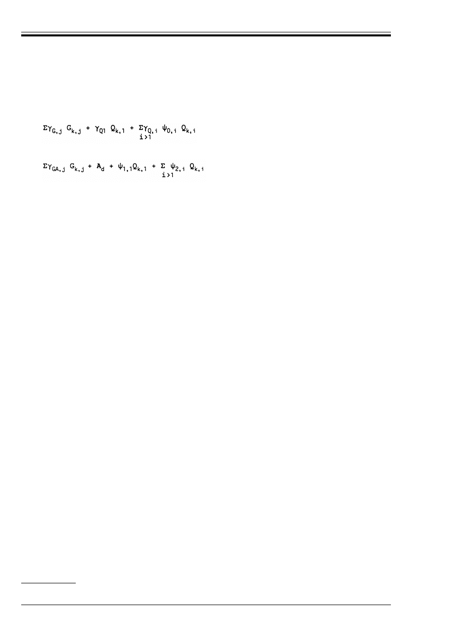
ENV 1995-1-1:1993
18
© BSI 02-2000
P(2) The design values of Table 2.3.2.2 shall be combined using the following rules (given in symbolic
form
16)
where symbols are defined as follows:
P(3) Combinations for accidental design situations either involve an explicit accidental action A or refer to
a situation after an accidental event (A = 0). Unless specified otherwise, *
GA
= 1 should be used.
P(4) Simplified combinations for building structures are given in 2.3.3.1.
2.3.2.3
Design values of permanent actions
P(1) In the various combinations defined above, those permanent actions that increase the effect of the
variable actions (i.e. produce unfavourable effects) shall be represented by their upper design values, those
that decrease the effect of the variable actions (i.e. produce favourable effects) by their lower design values
[see 2.2.2.4(3)].
P(2) Where the results of a verification will be very sensitive to variations of the magnitude of a permanent
action from place to place in the structure, the unfavourable and favourable parts of this action shall be
considered as individual actions. This applies in particular to the verification of static equilibrium. In the
aforementioned cases specific *
G
values need to be considered [see 2.3.3.1(3) for building structures].
P(3) In other cases, either the lower or upper design value (whichever gives the more unfavourable effect)
shall be applied throughout the structure.
P(4) For continuous beams the same design value of the self-weight may be applied to all spans.
2.3.3 Partial safety factors for ultimate limit states
2.3.3.1
Partial safety factors for actions on building structures
P(1) Partial safety factors for the persistent and transient design situations are given in Table 2.3.3.1.
P(2) For accidental design situation to which expression (2.3.2.2b) applies, the partial safety factors for
variable action are equal to unity.
— Persistent and transient design situations (fundamental combinations):
(2.3.2.2a)
— Accidental design situations (if not specified differently elsewhere)
(2.3.2.2b)
16)
Detailed rules on combinations of actions are given in ENV 1991 Eurocode 1.
G
k,j
characteristic values of permanent actions
Q
k,1
characteristic value of one of the variable actions
Q
k,i
characteristic value of the other variable actions
A
d
design value (specified value) of the accidental action
*
G,j
partial safety factors for permanent actions
*
GA,j
as *
G,j
but for accidental design situations
*
Q,i
partial safety factors for variable actions
>
0
,>
2
,>
2
factors defined in 2.2.2.3
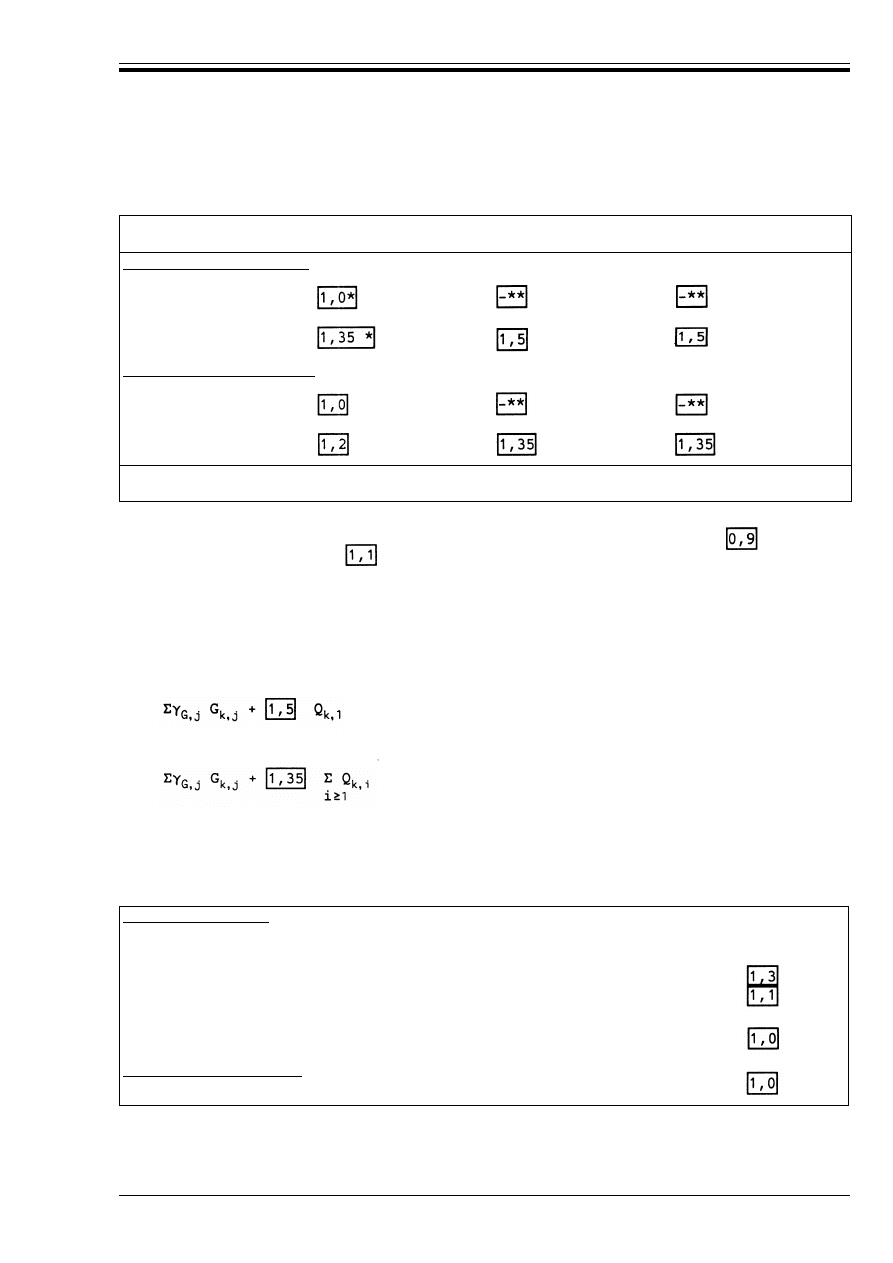
ENV 1995-1-1:1993
© BSI 02-2000
19
Table 2.3.3.1 — Partial safety factors for actions in building structures for persistent and
transient design situations
(3) Where according to 2.3.2.3(2), favourable and unfavourable parts of a permanent action need to be
considered as individual actions, the favourable part should be associated with *
G,inf
=
and the
unfavourable part with *
G,sup
=
.
(4) Reduced partial coefficients may be applied for one-storey buildings with moderate spans that are only
occasionally occupied (storage buildings, sheds, green houses, and buildings and small silos for agricultural
purposes), ordinary lighting masts, light partition walls, and sheeting.
For other structures normal coefficients should be applied.
(5) Adopting the * values given in Table 2.3.3.1, the expression (2.3.2.2 a) may be replaced by:
whichever gives the larger value.
2.3.3.2
Partial safety factors for materials
P(1) Partial safety factors for material properties (*
m
) are given in Table 2.3.3.2
Table 2.3.3.2 — Partial coefficients for material properties
(*
M
)
Permanent actions
(*
G
)
Variable actions one with
its characteristic value
(*
Q
) others with their
combination value
Normal partial coefficients
favourable effect (*
F,inf
)
unfavourable effect
Reduced partial coefficients
favourable effect
unfavourable effect
*
cf. 2.3.3.1(3) below
**
see ENV 1991 Eurocode 1; in normal cases on building structures *
Q,inf
= 0.
— considering only the most unfavourable variable action
(2.3.3.1a)
— considering all unfavourable variable actions
(2.3.3.1b)
Ultimate limit states
— fundamental combinations:
timber and wood-based materials
steel used in joints
— accidental combinations:
Serviceability limit states

ENV 1995-1-1:1993
20
© BSI 02-2000
2.3.4 Serviceability limit states
P(1) It shall be verified that
where symbols are defined as follows:
P(2) The partial safety factor for material properties (*
M
) is given in Table 2.3.3.2.
2.4 Durability
2.4.1 General
P(1) To ensure an adequately durable structure, the following interrelated factors shall be considered:
— the use of the structure
— the required performance criteria
— the expected environmental conditions
— the composition, properties and performance of the materials
— the shape of members and the structural detailing
— the quality of workmanship and level of control
— the particular protective measures
— the likely maintenance during the intended life.
P(2) The environmental conditions shall be estimated at the design stage to assess their significance in
relation to durability and to enable adequate provisions to be made for protection of the materials.
2.4.2 Resistance to biological organisms
P(1) Timber and wood-based materials shall either have adequate natural durability in accordance with
EN 350-2 for the particular hazard class (defined in EN 335-1 and EN 335-2, and prEN 335-3), or be given
a preservative treatment selected in accordance with prEN 351-1 and prEN 460.
2.4.3 Resistance to corrosion
P(1) Metal fasteners and other structural connections shall, where necessary, either be inherently
corrosion-resistant or be protected against corrosion.
(2) Examples of minimum corrosion protection or material specifications for different service classes
(see 3.1.5) are given in Table 2.4.3.
Table 2.4.3 — Examples of minimum material or corrosion protection specifications for
fasteners (related to ISO 2081)
a
E
d
kC
d
or E
d
kR
d
(2.3.4)
C
d
nominal value or a function of certain design properties of materials related to the design effects
of actions considered.
E
d
design effect of actions determined on the basis of the combination rules given in Chapter 4.
Fastener
Service Class
1
2
3
Nails, dowels screws
Bolts
Staples
Punched metal plate fasteners and steel plates
up to 3 mm thick
Steel plates over 3 mm up to 5 mm in thickness
Steel plates over 5 mm
None
None
Fe/Zn 12c
Fe/Zn 12c
None
None
None
Fe/Zn 12c
Fe/Zn 12c
Fe/Zn 12c
Fe/Zn 12c
None
Fe/Zn 25c
b
Fe/Zn 25c
b
Stainless steel
Stainless steel
Fe/Zn 25c
b
Fe/Zn 25c
b
a
If hot dip zinc coatings are used, then Fe/Zn 12c should be replaced by Z275, and Fe/Zn 25c should be replaced by Z350, both in
accordance with EN 10147.
b
For especially corrosive conditions consideration should be given to Fe/Zn 40, heavier hot dip coatings or stainless steel.

ENV 1995-1-1:1993
© BSI 02-2000
21
3 Material properties
3.1 General
3.1.1 Strength and stiffness parameters
P(1) Strength and stiffness parameters shall be determined on the basis of tests for the types of action
effects to which the material will be subjected in the structure, or on the basis of comparisons with similar
timber species or wood-based materials or on well-established relations between the different properties.
P(2) It shall be shown that the dimensional stability and environmental behaviour are satisfactory for the
intended purposes.
3.1.2 Characteristic values
P(1) Characteristic strength values are defined as the population 5-percentile values obtained from the
results of tests with a duration of 300s using test pieces at an equilibrium moisture content resulting from
a temperature of 20 °C and a relative humidity of 65 %.
P(2) Characteristic stiffness values are defined as either the population 5-percentile or the mean values
obtained under the same test conditions as defined in P(1).
P(3) The characteristic density is defined as the population 5-percentile value with mass and volume
corresponding to equilibrium moisture content at a temperature of 20 °C and a relative humidity of 65 %.
3.1.3 Stress-strain relations
P(1) Since the characteristic values are determined on the assumption of a linear relation between stress
and strain until failure, the strength verification of individual members shall also be based on such a linear
relation. For members subjected to combined bending and compression, however, a non linear relationship
(elastic-plastic) may be used.
3.1.4 Calculation models
P(1) The structural behaviour shall generally be assessed by calculating the action effects with a linear
material model (elastic behaviour). For lattice structures and other structures able to redistribute the
loads, elastic-plastic methods may be used for calculating the resulting stresses in the members.
3.1.5 Service classes
P(1) Structures shall be assigned to one of the service classes given below
17)
:
P(2) Service class 1: is characterized by a moisture content in the materials corresponding to a temperature
of 20 °C and the relative humidity of the surrounding air only exceeding 65 % for a few weeks per year
18)
.
P(3) Service class 2: is characterized by a moisture content in the materials corresponding to a temperature
of 20 °C and the relative humidity of the surrounding air only exceeding 85 % for a few weeks per year
19)
.
P(4) Service class 3: climatic conditions leading to higher moisture contents than in service class 2
20)
.
3.1.6 Load-duration classes
P(1) For strength and stiffness calculations actions shall be assigned to one of the load-duration classes
given in Table 3.1.6.
P(2) The load-duration classes are characterized by the effect of a constant load acting for a certain period
of time in the life of the structure. For a variable action the appropriate class shall be determined on the
basis of an estimate of the interaction between the typical variation of the load with time and the
rheological properties of the materials.
17)
The service class system is mainly aimed at assigning strength values and calculating deformations under defined
environmental conditions.
18)
In service class 1 the average moisture content in most softwoods will not exceed 12 %.
19)
In service class 2 the average moisture content in most softwoods will not exceed 20 %.
20)
Only in exceptional cases would covered structures be considered to belong to service class 3.

ENV 1995-1-1:1993
22
© BSI 02-2000
Table 3.1.6 — Load-duration classes
3.1.7 Modification factors for service class and duration of load
1) The values of the modification factor k
mod
given in Table 3.1.7 should be used.
2) If a load combination consists of actions belonging to different load-duration classes a value of k
mod
should be chosen which corresponds to the action with the shortest duration, e.g. for a dead load and a
short-term combination, a value of k
mod
corresponding to the short-term load should be used.
Table 3.1.7 — Values of
k
mod
Load-duration class
Order of accumulated duration of
characteristic load
Examples of loading
Permanent
Long-term
Medium-term
Short-term
Instantaneous
more than 10 years
6 months — 10 years
1 week — 6 months
less than one week
self weight
storage
imposed load
snow
a
and wind
accidental load
a
In areas which have a heavy snow load for a prolonged period of time, part of the load should be regarded as medium-term
Material/load-duration class
Service class
1
2
3
Solid and glued laminated timber
Plywood.
Permanent
Long-term
Medium-term
Short-term
Instantaneous
0,60
0,70
0,80
0,90
1,10
0,60
0,70
0,80
0,90
1,10
0,50
0,55
0,65
0,70
0,90
Particleboards to prEN 312-6
a
and prEN 312-7
OSB to prEN 300, Grades 3 and 4
Permanent
Long-term
Medium-term
Short-term
Instantaneous
0,40
0,50
0,70
0,90
1,10
0,30
0,40
0,55
0,70
0,90
—
—
—
—
—
Particleboards to prEN 312-4
a
and prEN 312-5
OSB to prEN 300, Grade 2
a
Fibreboards to prEN 622-5 (hardboard)
Permanent
Long-term
Medium-term
Short-term
Instantaneous
0,30
0,45
0,65
0,85
1,10
0,20
0,30
0,45
0,60
0,80
—
—
—
—
—
Fibreboards to prEN 622-3 (medium boards and hardboards)
Permanent
Long-term
Medium-term
Short-term
Instantaneous
0,20
0,40
0,60
0,80
1,10
—
—
—
—
—
—
—
—
—
—
a
Not to be used in service class 2

ENV 1995-1-1:1993
© BSI 02-2000
23
3.2 Solid timber
3.2.1 Grading
P(1) Timber shall be strength graded in accordance with rules ensuring that the properties of the timber
are satisfactory for use and especially that the strength and stiffness properties are reliable.
P(2) The grading rules shall be based on a visual assessment of the timber, on the non-destructive
measurement of one or more properties, or on a combination of the two methods.
P(3) Visual grading standards shall fulfill the minimum requirements given in prEN 518.
(4) Requirements for machine graded timber and for grading machines are given in prEN 519.
3.2.2 Characteristic strength and stiffness values and densities
P(1) Characteristic strength and stiffness values and densities shall be derived according to the method
given in prEN 384.
(2) Tests should be carried out in accordance with prEN 408 and prEN 1193.
P(3) The characteristic strength values shall be related to a depth in bending and width in tension
of 150 mm, to a specimen size of 45 mm × 180 mm × 70 mm for the tensile strength perpendicular to the
grain and to a uniformly stressed volume of 0,0005 m
3
for shear strength.
(4) A strength class system is given in prEN 384.
(5) For depths in bending or widths in tension of solid timber less than 150 mm the characteristic values
for f
m,k
and f
t,0,k
according to prEN 338 and prEN 384 may be increased by the factor k
h
where:
with h in mm for depth in bending or width in tension.
3.2.3 Timber sizes
P(1) The effective cross-section and geometrical properties of a structural member shall be calculated from
the target size, provided that the deviation of the cross-section from the target size
21)
is within the limits
of tolerance class 1 given in prEN 336.
P(2) Reductions in the cross-sectional area shall be taken into account, except for reductions caused by
— nails with a diameter of 6 mm or less, driven without predrilling
— symmetrically placed holes for bolts, dowels, screws and nails in columns
— holes in the compression area of members, if the holes are filled with a material of higher stiffness
than the wood.
(3) When assessing the effective cross-section at a joint with multiple fasteners, all holes within a distance
of half the minimum fastener spacing measured parallel to the grain from a given cross-section should be
considered as occurring at that cross-section.
3.2.4 Modification factors for service class and duration of load
(1) The values of the modification factor k
mod
given in Table 3.1.7 should be used.
3.2.5 Finger joints
P(1) Finger joints shall comply with prEN 385.
3.3 Glued laminated timber
3.3.1 Performance requirements
P(1) Glued laminated timber shall comply with prEN 386.
3.3.2 Characteristic strength and stiffness values
P(1) Characteristic strength and stiffness values shall either be determined on the basis of tests carried out
in accordance with prEN 408 and prEN 1193 or calculated on the basis of the properties of the laminates
and their joints.
(2) A method of calculating characteristic values and a strength class system are given in prEN 1194.
k
h
= min.
(150/h)
0,2
(3.2.2)
1,3
21)
The target size relates to a timber moisture content of 20 %.

ENV 1995-1-1:1993
24
© BSI 02-2000
P(3) The characteristic strength values shall be related to a depth in bending and width in tension
of 600 mm, to a volume of 0,01 m
3
for the tensile strength perpendicular to the grain and to a uniformly
stressed volume of 0,0005 m
3
for shear strength.
(4) For depths in bending or widths in tension of glued laminated timber less than 600 mm the
characteristic values for f
m,k
and f
t,0,k
given in prEN 1194 may be increased by the factor k
h
, where
with h in mm for depth in bending or width in tension.
3.3.3 Sizes of glued laminated timber
P(1) The effective cross-section and geometrical properties of a glued laminated member shall be calculated
from the target size, provided that the deviation of the cross-section from the target size
22)
is within the
limits given in prEN 390.
P(2) Reductions in the cross-sectional area shall be taken into account, except for reductions caused by
— nails with a diameter of 6 mm or less, driven without predrilling
— symmetrically placed holes for bolts, srews and nails in columns
— holes in the compression area of bending members, if the holes are filled with a material of higher
stiffness than the wood.
(3) When assessing the effective cross-section at a joint with multiple fasteners, all holes within a distance
of half the minimum fastener spacing measured parallel to the grain from a given cross-section should be
considered as occurring at that cross-section.
3.3.4 Modification factors for service class and duration of load
(1) The values of the modification factor k
mod
given in Table 3.1.7 should be used.
3.3.5 Large finger joints
P(1) Large finger joints shall comply with prEN 387.
P(2) Large finger joints shall not be used for products to be installed in service class 3, where the direction
of grain changes at the joint.
3.4 Wood-based materials
3.4.1 Plywood
3.4.1.1
Requirements
P(1) Plywood shall be produced so that it maintains its integrity and strength in the assigned service class
throughout the expected life of the structure.
(2) Plywood which complies with prEN 636-3 may be installed in service classes 1, 2 or 3.
(3) Plywood which complies with prEN 636-2 should only be installed in service classes 1 or 2.
(4) Plywood which complies with prEN 636-1 should only be installed in service class 1.
(5) Plywood for structural purposes should be balanced.
3.4.1.2
Characteristic strength and stiffness values
P(1) The characteristic values given in the relevant European Standards shall be used; when no values are
given in European Standards, characteristic strength and stiffness values shall be calculated according to
the method given in prEN 1058.
3.4.1.3
Modification factors for service class and duration of load
(1) The values of the modification factor k
mod
given in Table 3.1.7 should be used.
3.4.2 Particleboard
3.4.2.1
Requirements
P(1) Particleboard shall be produced so that it maintains its integrity and strength in the assigned service
class throughout the expected life of the structure.
k
h
= min.
(600/h)
0,2
(3.3.2)
1,15
22)
The target size relates to a timber moisture content of 12 %.

ENV 1995-1-1:1993
© BSI 02-2000
25
(2) Particleboard which complies with prEN 312-5 or prEN 312-7 should only be installed in service
classes 1 or 2.
(3) Particleboard which complies with prEN 312-4 or prEN 312-6 should only be installed in service class 1.
(4) Oriented strand board which complies with prEN 300 grades OSB 3 or 4 should only be installed in
service classes 1 or 2.
(5) Oriented strand board which complies with prEN 300, grade OSB 2 should only be installed in service
class 1.
3.4.2.2
Characteristic strength and stiffness values
P(1) The characteristic values given in the relevant European Standards shall be used; when no values are
given in European Standards, characteristic strength and stiffness values shall be calculated according to
the method given in prEN 1058.
3.4.2.3
Modification factors for service class and duration of load
(1) Values of the modification factor k
mod
are given in Table 3.1.7.
3.4.3 Fibreboard
3.4.3.1
Requirements
P(1) Fibreboard shall be produced so that it maintains its integrity and strength in the assigned service
class throughout the expected life of the structure.
(2) Fibreboards which comply with prEN 622-5 should only be installed in service classes 1 or 2.
(3) Fibreboards which comply with prEN 622-3 should only be installed in service class 1.
3.4.3.2
Characteristic strength and stiffness values
P(1) The characteristic values given in the relevant European Standards shall be used; when no values are
given in European Standards, characteristic strength and stiffness values shall be calculated according to
the method given in prEN 1058.
3.4.3.3
Modification factors for service class and duration of load
(1) The values of the modification factor k
mod
given in Table 3.1.7 should be used.
3.5 Adhesives
P(1) Adhesives for structural purposes shall produce joints of such strength and durability that the
integrity of the bond is maintained in the assigned service class throughout the expected life of the
structure.
(2) Adhesives which comply with Type I specification as defined in EN 301 may be used in all service
classes.
(3) Adhesives which comply with Type II specification as defined in EN 301 should only be used in service
classes 1 or 2 and not under prolonged exposure to temperatures in excess of 50 °C.
4 Serviceability limit states
4.1 General requirements
P(1) The deformation of a structure which results from the effects of actions (such as axial and shear forces,
bending moments and joint slip) and from moisture shall remain within appropriate limits, having regard
to the possibility of damage to surfacing materials, ceilings, partitions and finishes, and to the functional
needs as well as any requirements of appearance.
(2) Combinations of actions for serviceability limit states should be calculated from the expression
(3) The instantaneous deformation, U
inst
, under an action should be calculated using the mean value of the
appropriate stiffness moduli, and the instantaneous slip modulus for the serviceability limit state K
ser
,
determined by testing according to the method for determining k
s
(= K
ser
) given in EN 26891.
(4.1a)

ENV 1995-1-1:1993
26
© BSI 02-2000
(4) The final deformation, u
fin
, under an action should be calculated as
where k
def
is a factor which takes into account the increase in deformation with time due to the combined
effect of creep and moisture. The values of k
def
given in Table 4.1 should be used.
(5) The final deformation of an assembly fabricated from members which have different creep properties
should be calculated using modified stiffness moduli, which are determined by dividing the instantaneous
values of the modulus for each member by the appropriate value of (1 + k
def
).
(6) If a load combination consists of actions belonging to different load duration classes, the contribution of
each action to the total deflection should be calculated separately using the appropriate k
def
values.
Table 4.1 — Values of
k
def
for timber, wood-based materials and joints
u
fin
= u
inst
(1 + k
def
)
(4.1b)
Material/load-duration class
Service class
1
2
3
Solid timber
a
glued laminated timber
Permanent
Long-term
Medium-term
Short-term
0,60
0,50
0,25
0,00
0,80
0,50
0,25
0,00
2,00
1,50
0,75
0,30
Plywood
Permanent
Long-term
Medium-term
Short-term
0,80
0,50
0,25
0,00
1,00
0,60
0,30
0,00
2,50
1,80
0,90
0,40
Particleboard to prEN 312-6
b
and prEN 312-7
OSB to prEN 300 Grades 3 and 4
Permanent
Long-term
Medium-term
Short-term
1,50
1,00
0,50
0,00
2,25
1,50
0,75
0,30
—
—
—
—
Particleboard to prEN 312-4
b
and prEN 312-5
OSB to prEN 300, Grade 2
b
Fibreboards to prEN 622-5
Permanent
Long-term
Medium-term
Short-term
2,25
1,50
0,75
0,00
3,00
2,00
1,00
0,40
—
—
—
—
Fibreboards to prEN 622-3
Permanent
Long-term
Medium-term
Short-term
3,00
2,00
1,00
0,35
—
—
—
—
—
—
—
—
a
For solid timber which is installed at or near fibre saturation points, and which is likely to dry out under load, the value of k
def
should be increased by 1,0.
b
Not to be used in service class 2.
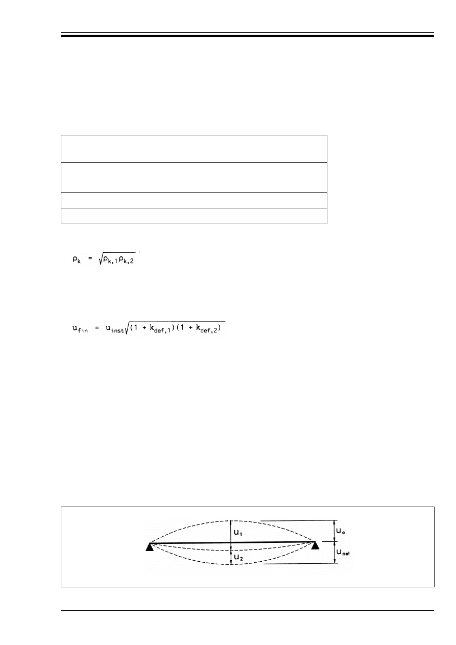
ENV 1995-1-1:1993
© BSI 02-2000
27
4.2 Joint slip
(1) For joints made with dowel-type fasteners the instantaneous slip modulus K
ser
per shear plane per
fastener under service load should be taken from Table 4.2 with @
k
in kg/m
3
and d in mm.
Table 4.2 — Values of
K
ser
for dowel-type fasteners in
N/mm
(2) If the characteristic densities of the two jointed members are different (@
k,1
and @
k,2
) then @
k
in above
formulae @
k
should be taken as
(3) The final joint slip (u
fin
) should be taken as
(4) The final deformation of a joint made from members with different creep properties (k
def,1
, k
def,2
),
should be calculated as
(5) For bolted joints the instantaneous slip u
inst
under service load should be taken as
with K
ser
for dowels (see Table 4.2).
(6) The final joint slip for bolts (u
fin
) is given by
where u
inst
is the instantaneous dowel slip.
4.3 Limiting values of deflection
4.3.1 Beams
(1) The components of deflection are shown in Figure 4.3.1, where the symbols are defined as follows:
Fastener type
Timber-to-timber
Panel-to-timber
Steel-to-timber
Dowels
Screws
Nails (with predrilling)
@
k
1,5
d/20
Nails (without predrilling)
@
k
l,5
d
0,8
/25
Staples
@
k
1,5
d
0,8
/60
(4.2a)
u
fin
= u
inst
(1 + k
def
)
(4.2b)
(4.1c)
u
inst
= 1 mm + F/K
ser
(4.2b)
u
fin
= 1 mm + u
inst
(1 + k
def
)
(4.2c)
u
0
precamber (if applied)
u
1
deflection due to permanent loads
u
2
deflection due to variable loads
Figure 4.3.1 — Components of deflection
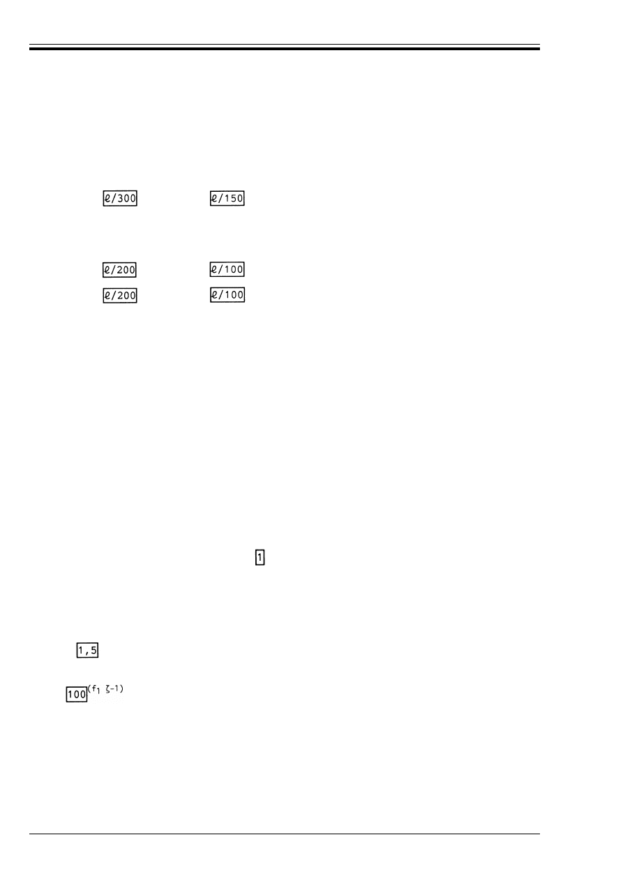
ENV 1995-1-1:1993
28
© BSI 02-2000
The net deflection below the straight line joining the supports, u
net
, is given by
(2) In cases where it is appropriate to limit the instantaneous deflections due to variable actions, the
following values are recommended unless special conditions call for other requirements:
where = is the beam span or the length of a cantilever.
(3) In cases where it is appropriate to limit the final deflection, u
fin
, the following values are recommended
unless special conditions call for other requirements:
4.3.2 Trusses
(1) For trusses the limiting values of deflection for beams apply both to the complete span, and to the
individual deflection of members between nodes.
4.4 Vibrations
4.4.1 General
P(1) It shall be ensured that the actions which are anticipated to occur often do not cause vibrations that
can impair the function of the structure or cause unacceptable discomfort to the users.
(2) The floor vibration level should be estimated by measurements or by calculation taking into account the
expected stiffness of the floor and the modal damping ratio.
(3) The mean values of the appropriate stiffness moduli should be used for the calculations.
(4) Unless other values are proved to be more appropriate, a modal damping ratio of M = 0,01 (i.e. 1 %)
should be assumed.
4.4.2 Vibrations from machinery
P(1) Vibrations caused by rotating machinery and other operational equipment shall be limited for the
unfavourable combinations of permanent load and variable loads that can be expected.
(2) Acceptable levels for continuous floor vibration should be taken from Figure 5a in Appendix A of
IS0 2631-2 (1989) with a multiplying factor of .
4.4.3 Residential floors
(1) For residential floors with a fundamental frequency k 8 Hz (f
1
k 8 Hz) a special investigation should
be made.
(2) For residential floors with a fundamental frequency greater than 8 Hz (f
1
> 8 Hz) the following
requirements should be satisfied:
and
where u is the maximum vertical deflection caused by a vertical concentrated static force F, and v is the
unit impulse velocity response, i.e. the maximum initial value of the vertical floor vibration velocity
(in m/s) caused by an ideal unit impulse (1 Ns) applied at the point of the floor giving maximum response.
Components above 40 Hz may be disregarded.
(3) The calculation should be made under the assumption of unloaded floor, i.e., only the mass
corresponding to the self-weight of the floor and other permanent actions.
u
net
= u
1
+ u
2
– u
0
(4.3.1)
u
2, inst
k
(cantilever
)
(4.3.2)
u
2, fin
k
(cantilever
)
(4.3.3)
u
net, fin
k
(cantilever
)
(4.3.4)
u/F k mm/kN
(4.4.3a)
v k m/(Ns
2
)
(4.4.3b)
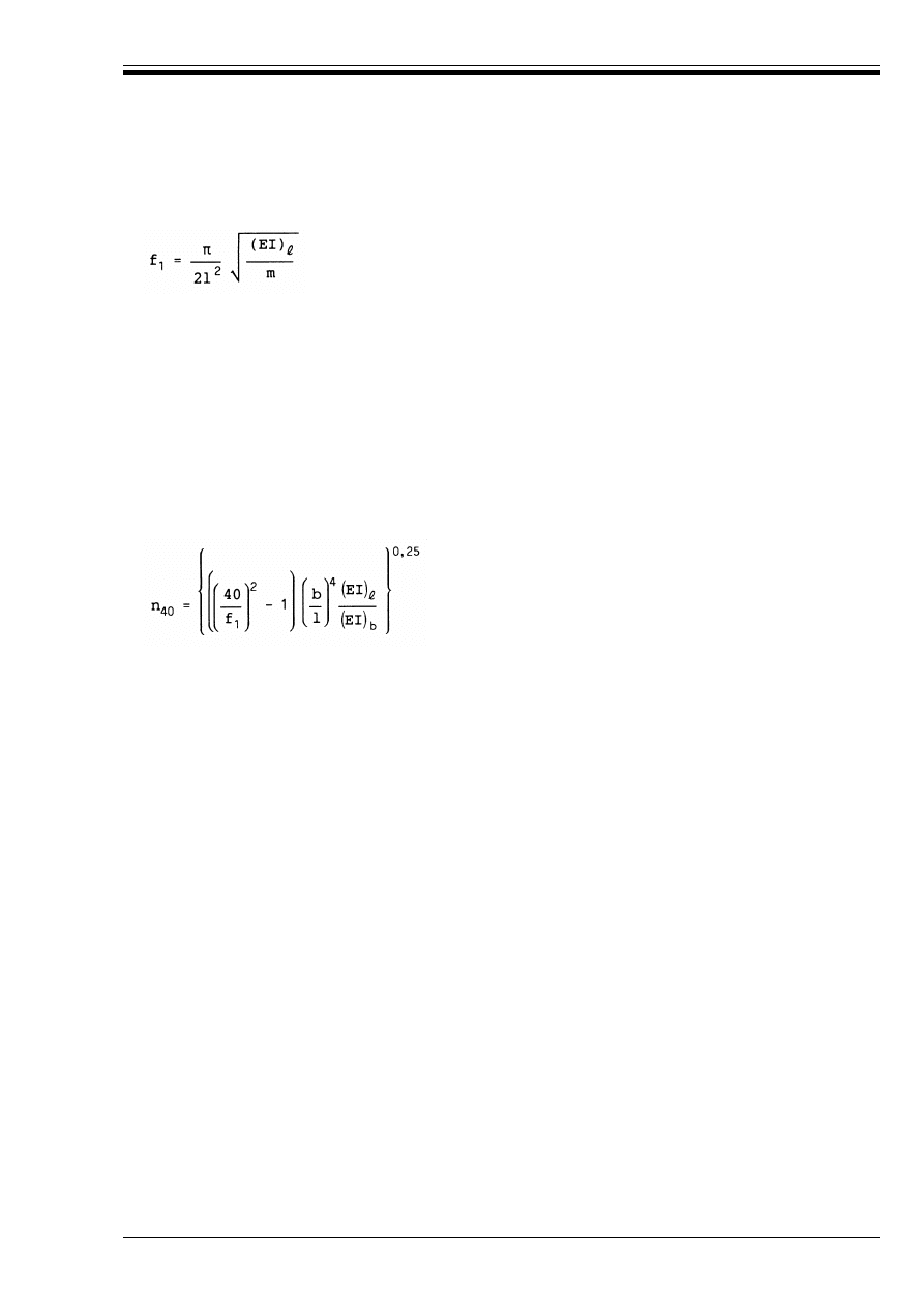
ENV 1995-1-1:1993
© BSI 02-2000
29
(4) For a rectangular floor l × b simply supported along all four edges and with timber beams having a
span l the fundamental frequency f
1
may approximately be calculated as
where
(5) The value of v may as an approximation be taken as
where n
40
is the number of first-order modes with natural frequencies below 40 Hz and b is the floor width
in m.
The value of n
40
may be calculated from
where (EI)
b
is the equivalent plate bending stiffness of the floor about an axis parallel to the beams, where
(EI)
b
< (EI)
=
.
5 Ultimate limit states
5.1 Basic rules
5.1.1 General
P(1) This section applies to members of solid timber or glued laminated timber.
5.1.2 Tension parallel to the grain
P(1) The following condition shall be satisfied:
5.1.3 Tension perpendicular to the grain
P(1) For a uniformly stressed volume V in m
3
the following condition shall be satisfied:
where V
o
is the reference volume of 0,01 m
3
.
5.1.4 Compression parallel to the grain
P(1) The following condition shall be satisfied:
P(2) A check shall also be made of the instability condition (see 5.2.1).
5.1.5 Compression at an angle to the grain
P(1) For compression perpendicular to the grain the following condition shall be satisfied:
(4.4.3c)
m
mass per unit area in kg/m
2
=
floor span in m
(EI)
=
equivalent plate bending stiffness of the floor about an axis perpendicular to beam direction in
Nm
2
/m
v = 4(0,4 + 0,6n
40
)/(mbl + 200) m/Ns
2
(4.4.3d)
(4.4.3e)
B
t,0,d
k f
t,0,d
(5.1.2)
B
t,90,d
k f
t,90,d
for solid timber
(5.1.3a)
B
t,90,d
k f
t,90,d
(V
0
/V)
0,2
for glued laminated timber
(5.1.3b)
B
c,0,d
k f
c,0,d
(5.1.4)
B
c,90,d
k k
c,90
f
c,90,d
(5.1.5a)
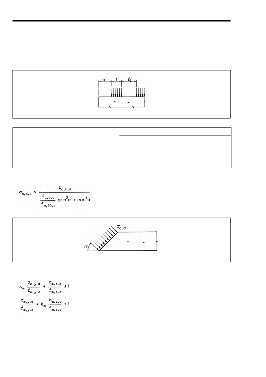
ENV 1995-1-1:1993
30
© BSI 02-2000
where k
c,90
(see Table 5.1.5) takes into account that the load can be increased if the loaded length, l in
Figure 5.1.5a, is short.
Table 5.1.5 — Values of k
c,90
(2) The compression stresses at an angle ! to the grain, (see Figure 5.1.5b), should satisfy the following
condition:
5.1.6 Bending
P(1) The following conditions shall be satisfied:
where B
m,y,d
and B
m,z,d
are the design bending stresses about the principal axes as shown in Figure 5.1.6,
and f
m,y,d
and f
m,z,d
are the corresponding design bending strengths.
(2) The value of the factor k
m
should be taken as follows:
— for rectangular sections; k
m
= 0,7
— for other cross-sections; k
m
= 1,0
Figure 5.1.5a — Compression perpendicular to the grain
l
1
k 150 mm
l
1
> 150 mm
a U 100 mm
a < 100 mm
150 mm >
15 mm >
1 U 150 mm
1 U 15 mm
1
1
1
1
1
1,8
1
1 + a/125
(5.1.5b)
Figure 5.1.5b — Stresses at an angle to the grain
(5.1.6a)
(5.1.6b)
1 150 1
–
170
-------------------
+
1 a 150 1
–
(
)
17000
----------------------------
+
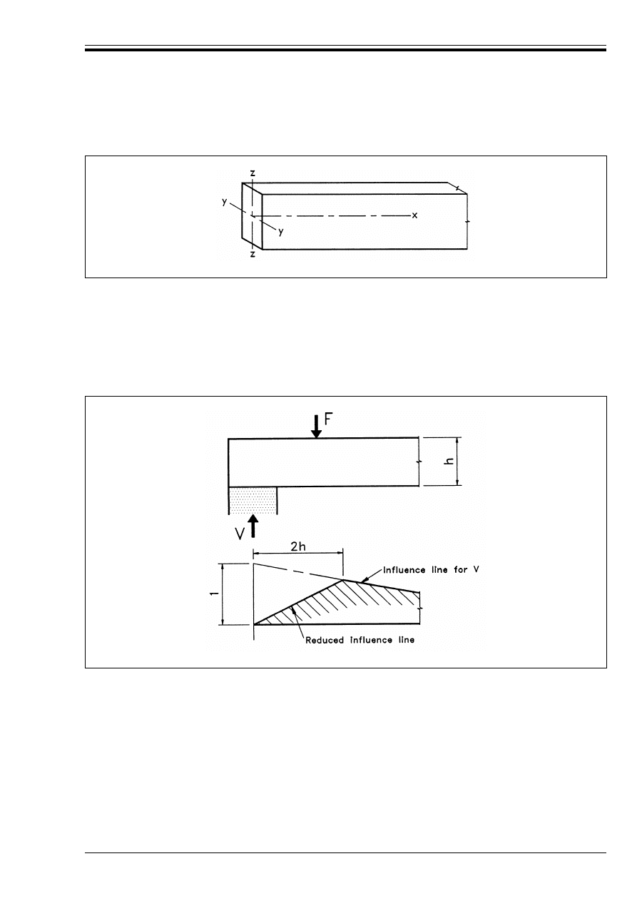
ENV 1995-1-1:1993
© BSI 02-2000
31
P(3) A check shall also be made of the instability condition (see 5.2.2).
5.1.7 Shear
5.1.7.1
General
P(1) The following condition shall be satisfied:
(2) At beam ends, the contribution to the total shear force of a point load F within a distance 2h of the
support may be reduced according to the influence line shown in Figure 5.1.7.1.
5.1.7.2
End-notched beams
P(1) For beams notched at the ends, (see Figure 5.1.7.2), the shear stress shall be calculated using the
effective (reduced) depth h
e
.
P(2) For beams notched on the loaded side (see Figure 5.1.7.2a) the effect of stress concentrations at the
re-entrant angle shall be taken into consideration.
(3) It should be verified that
For beams notched at the unloaded side
Figure 5.1.6 — Beam axes
E
d
k f
v,d
(5.1.7.1)
Figure 5.1.7.1 — Reduced influence line for point loads
E
d
= 1,5V/bh
e
k k
v
f
v,d
(5.1.7.2a)
k
v
= 1
(5.1.7.2b)
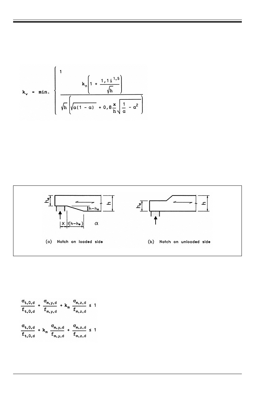
ENV 1995-1-1:1993
32
© BSI 02-2000
For beams notched at the loaded side
The value of the factor k
n
should be taken as follows:
— for solid timber: k
n
= 5
— for glued laminated timber: k
n
= 6.5
The symbols are defined as follows:
5.1.8 Torsion
P(1) The torsional stresses shall satisfy the following condition:
5.1.9 Combined bending and axial tension
P(1) The following conditions shall be satisfied:
where B
t,0,d
is the design tensile stress and f
t,0,d
is the design tensile strength.
(2) The values of k
m
given in 5.1.6 apply.
(5.1.7.2c)
(5.1.7.2d)
h
beam depth in mm
x
distance from line of action to the corner
a
h
e
/h
i
notch inclination [see Figure 5.1.7.2(a)]
Figure 5.1.7.2 (a) and (b) — End-notched beams
E
tor,d
k f
v,d
(5.1.8)
(5.1.9a)
(5.1.9b)
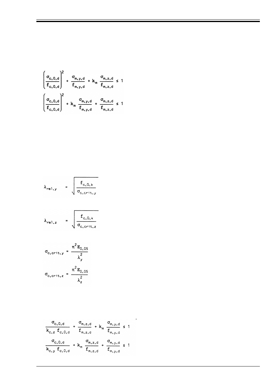
ENV 1995-1-1:1993
© BSI 02-2000
33
5.1.10 Combined bending and axial compression
P(1) The following conditions shall be satisfied:
where B
c,0,d
is the design compressive stress and f
c,0,d
is the design compressive strength.
(2) The values of k
m
given in 5.1.6 apply.
P(3) A check shall also be made of the instability condition (see 5.2.1)
5.2 Columns and beams
5.2.1 Columns
P(1) The bending stresses due to initial curvature, eccentricities and induced deflection shall be taken into
account, in addition to those due to any lateral load.
(2) The relative slenderness ratios are defined by:
and
where
(3) For both 2
rel,z
k 0,5 and 2
rel,y
k 0,5 the stresses should satisfy the conditions in 5.1.10a and b.
(4) In all other cases the stresses should satisfy the following conditions:
(5.1.10a)
(5.1.10b)
(5.2.1a)
(5.2.1b)
(5.2.1c)
(5.2.1d)
2
y
and 2
rel,y
correspond to bending about the y-axis (deflection in the z-direction).
2
z
and 2
rel,z
correspond to bending about the z-axis (deflection in the y-direction).
(5.2.1e)
(5.2.1f)
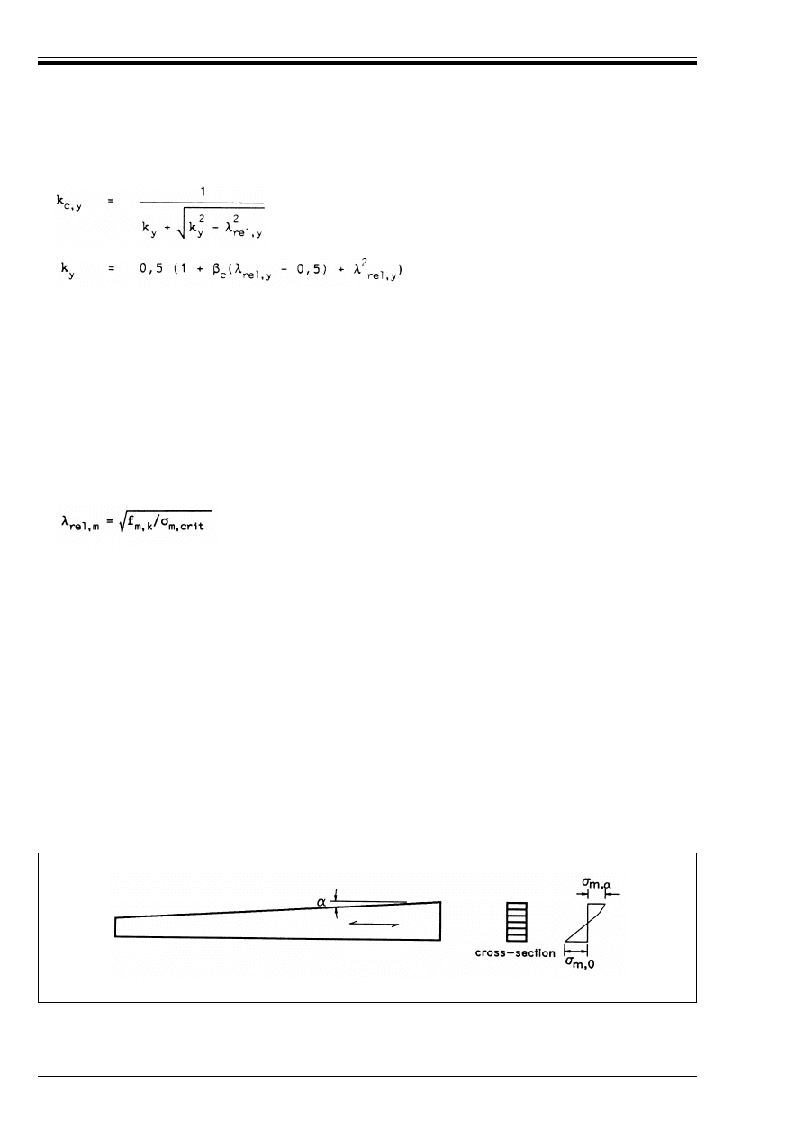
ENV 1995-1-1:1993
34
© BSI 02-2000
with
The symbols are defined as follows:
5.2.2 Beams
P(1) The bending stresses due to initial curvature, eccentricities and induced deflection shall be taken into
account, in addition to those from any lateral loads
(2) The relative slenderness for bending is defined by
where B
m,crit
is the critical bending stress calculated according to the classical theory of stability,
with 5-percentile stiffness values.
(3) The stresses should satisfy the following condition:
where k
crit
is a factor which takes into account the reduced strength due to lateral buckling.
(4) For beams with an initial lateral deviation from straightness within the limits defined in chapter 7, k
crit
may be determined from (5.2.2c–e).
(5) The factor k
crit
may also be put equal to 1 for a beam where lateral displacement of the compression side
is prevented throughout its length and where torsional rotation is prevented at the supports.
5.2.3 Single tapered beams
P(1) The influence of the taper on the bending stresses parallel to the surface shall be taken into account.
(similarly for k
c,z
)
(5.2.1g)
(similarly for k
c,z
)
(5.2.1h)
B
m
bending stress due to any lateral loads
"
c
a factor for members within the straightness limits defined in chapter 7:
— for solid timber: "
c
= 0,2
— for glued laminated timber "
c
= 0,1
k
m
as given in 5.1.6
(5.2.2a)
B
md
k k
crit
f
m,d
(5.2.2b)
k
crit
=
1
1,56 – 0,752
rel,m
1/2
2
rel,m
for
for 0,75
for 1,4
<
<
2
rel,m
k 0,75
2
rel,m
k 1,4
2
rel,m
(5.2.2c)
(5.2.2d)
(5.2.2e)
Figure 5.2.3 — Single tapered beam
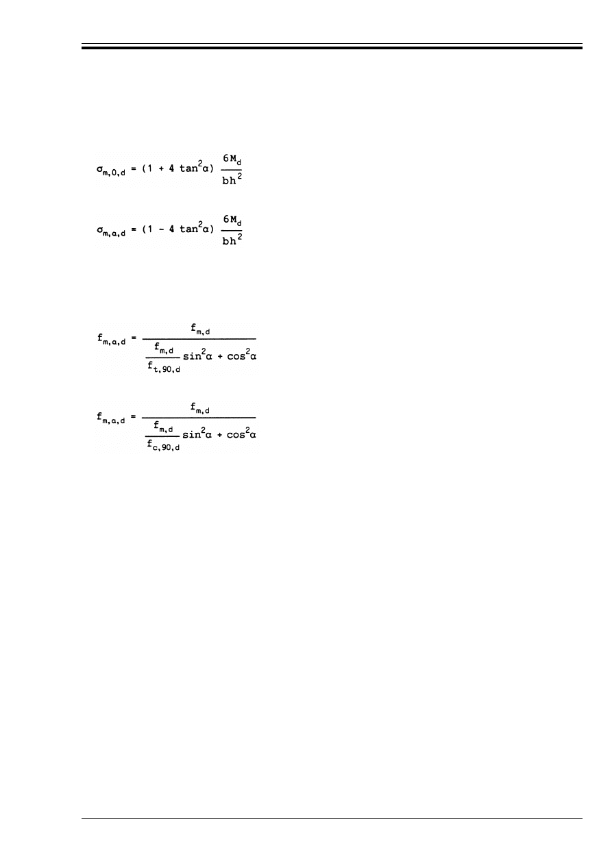
ENV 1995-1-1:1993
© BSI 02-2000
35
(2) Where the grain is parallel to one of the surfaces, and the angle of taper ! k 10°, the bending stress in
the outermost fibre, where the grain is parallel to the surface, should be calculated as
and as
on the tapered side.
(3) In the outermost fibre at the tapered edge the stresses should satisfy the following condition:
where
in the case of tensile stresses parallel to the tapered edge and
in case of compressive stresses parallel to the tapered edge.
5.2.4 Double tapered, curved and pitched cambered beams
P(1) The requirements of section 5.2.3 apply to the lengths of the beam which have a single taper.
P(2) In the apex zone (see Figure 5.2.4), the bending stresses shall satisfy the following condition:
where the factor k
r
takes into account the reduction in strength due to bending of the laminates during
production.
(5.2.3a)
(5.2.3b)
B
m,a,d
k f
m,a,d
(5.2.3c)
(5.2.3d)
(5.2.3e)
B
m,d
k k
r
f
m,d
(5.2.4a)
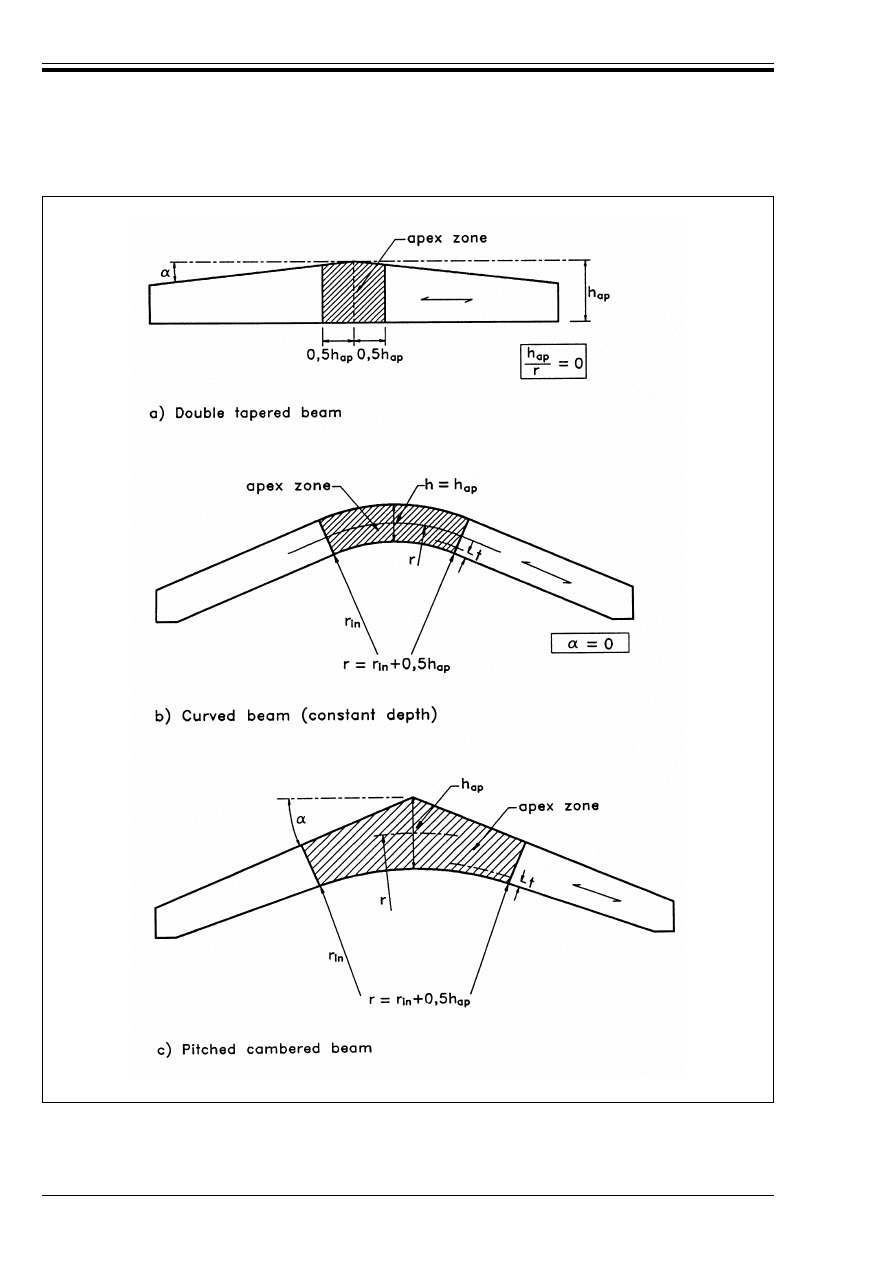
ENV 1995-1-1:1993
36
© BSI 02-2000
Figure 5.2.4 — Double tapered a), curved b) and pitched cambered c) beams
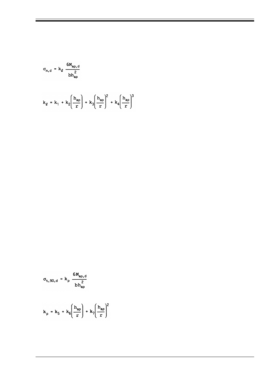
ENV 1995-1-1:1993
© BSI 02-2000
37
(3) The apex bending stress should be calculated as follows:
where h
ap
,r and ! are defined in Figure 5.2.4, and
where
(4) For double tapered beams k
r
= 1. For curved and pitched cambered beams k
r
should be taken as
where r
in
is the radius of the inner beam face and t is the laminate thickness.
(5) In the apex zone the greatest tensile stress perpendicular to the grain should satisfy the following
condition:
where the symbols are defined as follows:
(6) The greatest tensile stress perpendicular to the grain due to the bending moment should be calculated
as follows:
where
(5.2.4b)
(5.2.4c)
k
1
= 1 + 1,4 tan ! + 5,4 tan
2
!
(5.2.4d)
k
2
= 0,35 – 8 tan !
(5.2.4e)
k
3
= 0,6 + 8,3 tan ! – 7,8 tan
2
!
(5.2.4f)
k
4
= 6 tan
2
!
(5.2.4g)
k
r
=
1
for r
in
/t U 240
(5.2.4h)
0,76 + 0,001 r
in
/t
for r
in
/t < 240
(5.2.4j)
B
t,90,d
k k
dis
(V
0
/V)
0,2
f
t,90,d
(5.2.4k)
k
dis
a factor which takes into account the effect of the stress distribution in the apex zone, with the
following values:
— for double tapered and curved beams: k
dis
= 1,4
— for pitched cambered beams: k
dis
= 1,7.
V
0
reference volume of 0,01 m
3
V
volume in m
3
of the apex zone (see Figure 5.2.4). As a maximum, V should be taken as 2V
b
/3,
where V
b
is the total volume of the beam
(5.2.4l)
(5.2.4m)
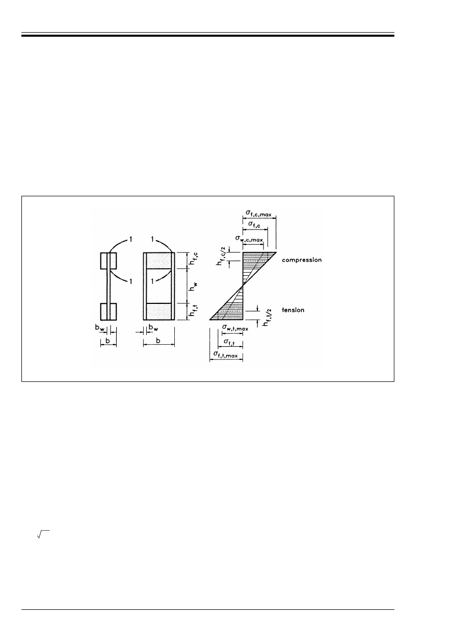
ENV 1995-1-1:1993
38
© BSI 02-2000
with
5.3 Components
5.3.1 Glued thin-webbed beams
P(1) A linear variation of strain over the depth of the beam shall be assumed.
(2) The axial stresses in the flanges should satisfy the following conditions:
where the symbols are defined as follows:
(3) The factor k
c
may be determined (conservatively, especially for box beams) according to 5.2.1 with
2
z
=
l
c
/b, where l
c
is the distance between the sections where lateral deflection of the compression
flange is prevented, and b is given in Figure 5.3.1. If a special investigation is made into the lateral
instability of the beam as a whole, k
c
= 1 may be assumed.
k
5
= 0,2 tan !
(5.2.4n)
k
6
= 0,25 – 1,5 tan ! + 2,6 tan
2
!
(5.2.4o)
k
7
= 2,1 tan ! – 4 tan
2
!
(5.2.4p)
Figure 5.3.1 — Thin-webbed beams
B
f,c,max,d
k f
m,d
(5.3.1a)
B
f,t,max,d
k f
m,d
(5.3.1b)
B
f,c,d
k k
c
f
c,0,d
(5.3.1c)
B
f,t,d
k f
t,0,d
(5.3.1d)
B
f,c,max,d
extreme fibre flange design compressive stress
B
f,c,max,d
extreme fibre flange design tensile stress
B
f,c,d
mean flange design compressive stress
B
f,t,d
mean flange design tensile stress
k
c
a factor which takes into account lateral instability.
1
2

ENV 1995-1-1:1993
© BSI 02-2000
39
(4) The axial stresses in the webs should satisfy the following conditions:
where B
w,c,d
and B
w,t,d
are the design compressive and design tensile stresses, and f
c,w,d
and f
t,w,d
the
design compressive and design tensile bending strengths, of the webs.
(5) Unless other values are given the design tensile strength and compressive strength of the webs should
be taken as the in-plane design tensile or compressive strength.
(6) It should be verified that any splices have sufficient strength.
(7) Unless a detailed buckling analysis is made it should be verified that
and
where symbols are defined as follows:
(8) For sections 1-1 in Figure 5.3.1 it should be verified that
where E
mean
is the shear stress at the sections, assuming a uniform distribution, f
v,90,d
is the design planar
(rolling) shear strength of the web and h
f
is either h
f,c
or h
f,t
.
5.3.2 Glued thin-flanged beams
P(1) A linear variation of strain over the depth of the beam shall be assumed.
P(2) Account shall be taken of the non-uniform distribution of stresses in the flanges due to shear lag and
buckling.
(3) Unless a more detailed calculation is made, the assembly should be considered as a number of I-beams
or U-beams (see Figure 5.3.2) with effective flange widths b
ef
, where
or
The values of b
c,ef
and b
t,ef
should not be greater than the maximum value calculated for shear lag. In
addition the value of b
c,ef
should not be greater than the maximum value calculated for plate buckling.
(4) The maximum effective flange widths due to the effects of shear lag and plate buckling are given in
Table 5.3.2, where l is the span of the beam.
Table 5.3.2 — Maximum effective flange widths due to the effect of
shear lag and plate buckling
B
w,c,d
k f
c,w,d
(5.3.1e)
B
w,t,d
k f
t,w,d
(5.3.1f)
h
w
k 70b
w
(5.3.1g)
V
d
k
b
w
h
w
(1 + 0,5 (h
f,t
+ h
f,c
)/h
w
) f
v,0,d
for h
w
k 35b
w
(5.3.1h)
35b
w
2
(1 + 0,5 (h
f,t
+ h
f,c
)/h
w
) f
v,0,d
for 35b
w
k h
w
k 70b
w
(5.3.1j)
h
w
web depth
h
f,c
compression flange depth
h
f,t
tension flange depth
b
w
web width
f
v,0,d
design panel shear strength
E
mean,d
k
f
v,90,d
for h
f
k 4 b
w
(5.3.1k)
f
v,90,d
(4b
w
/h
w
)
0.8
for h
f
> 4 b
w
(5.3.1l)
b
ef
= b
c,ef
+ b
w
(or b
t,ef
+ b
w
)
(5.3.2a)
b
ef
= 0,5b
c,ef
+ b
w
(or 0,5b
t,ef
+ b
w
)
(5.3.2b)
Flange material
Shear lag
Plate buckling
Plywood, with grain direction in the outer plies:
— parallel to the webs
— perpendicular to the webs
Oriented strand board
Particleboard or fibreboard with random fibre orientation
0,1l
0,1l
0,15l
0,2l
25h
f
20h
f
25h
f
30h
f
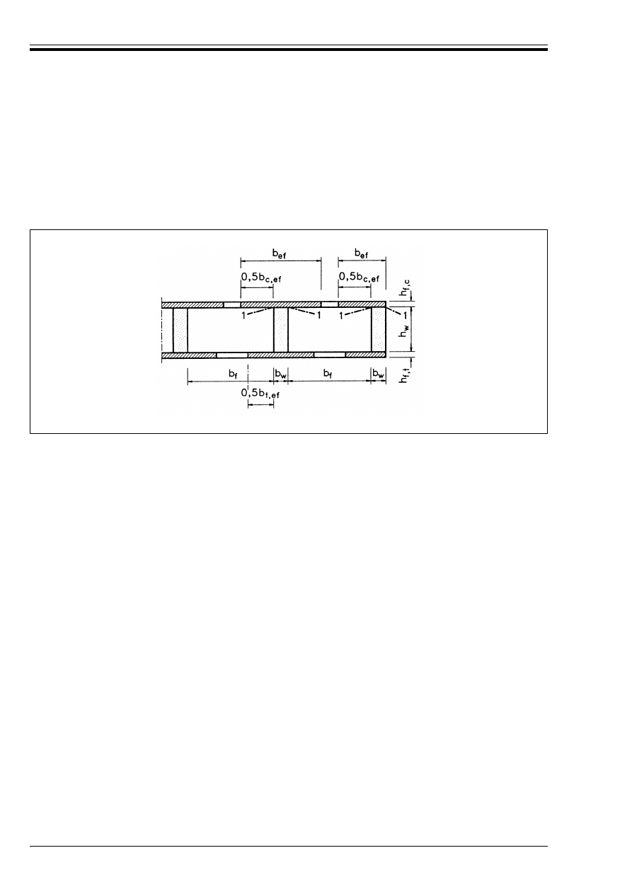
ENV 1995-1-1:1993
40
© BSI 02-2000
(5) Unless a detailed buckling investigation is made, the free flange width should not be greater than twice
the effective width due to plate buckling.
(6) For sections 1-1 in Figure 5.3.2 it should be verified that
where E
mean,d
is the design shear stress at the sections, assuming a uniform distribution, and f
v,90,d
is the
design planar (rolling) shear strength of the flange.
(7) The axial stresses in the flanges, based on the relevant effective flange width, should satisfy the
following conditions:
where the symbols are defined as follows:
(8) It should be verified that any splices have sufficient strength.
5.3.3 Mechanically jointed beams
P(1) If the cross-section of a structural member is composed of several parts connected by mechanical
fasteners, consideration shall be given to the influence of the slip occurring in the joints.
(2) Calculations should be carried out assuming a linear relationship between force and slip.
(3) For dowel-type fasteners the instantaneous slip modulus K
u
per shear plane for ultimate limit state
design should be taken as
Values of K
ser
are given in 4.2.
(4) If the spacing of the fasteners varies uniformly in the longitudinal direction according to the shear force
between S
min
and S
max
(k 4s
min
), an effective value s
ef
may be used, where:
(5) The stresses should as a minimum be calculated at instantaneous and final deformation, using the
appropriate values of k
def
from Table 4.1.
E
mean,d
k f
v,90,d
(5.3.2c)
Figure 5.3.2 — Thin-flanged beam
B
f,c,d
k f
f,c,d
(5.3.2d)
B
f,t,d
k f
f,t,d
(5.3.2e)
B
f,c,d
(f
f,c,d
)
mean flange design compressive stress
B
f,t,d
(f
f,t,d
)
mean flange design tensile stress
f
f,c,d
flange design compressive strength
f
f,t,d
flange design tensile strength
K
u
= 2 K
ser
/3
(5.3.3a)
s
ef
= 0,75 s
min
+ 0,25 s
max
(5.3.3b)
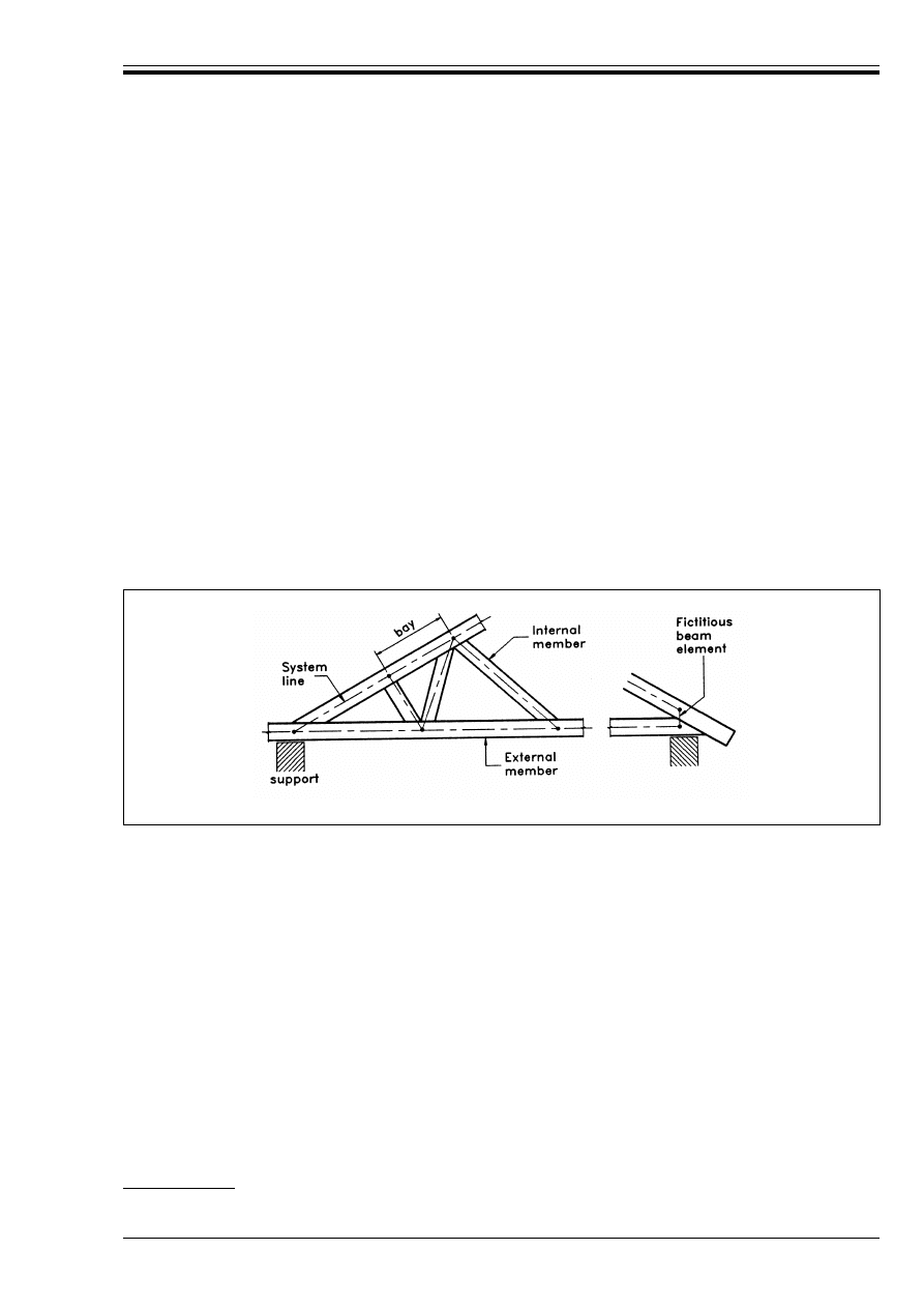
ENV 1995-1-1:1993
© BSI 02-2000
41
(6) A method for the calculation of the load-carrying capacity of mechanically jointed beams is given
in Annex B
23)
.
5.3.4 Mechanically jointed and glued columns
P(1) The deformations due to slip in joints, to shear and bending in packs, gussets, shafts and flanges, and
to the axial forces in the lattice shall be taken into account.
(2) A method for the calculation of the load-carrying capacity of I- and box-columns, spaced columns and
lattice columns is given in Annex C.
5.4 Assemblies
5.4.1 Trusses
5.4.1.1
General
P(1) Unless a more general model is used, trusses shall be represented for the purpose of analysis by beam
elements set out along system lines and connected together at nodes (e.g. as shown in Figure 5.4.1.1).
P(2) The system lines for all members shall lie within the member profile, and for external members shall
coincide with the member centre line.
(3) Fictitious beam elements may be used to model eccentric connections or supports. The orientation of
fictitious beam elements should coincide as closely as possible with the direction of the force in the member.
(4) In the analysis the geometric non-linear behaviour of a member in compression (buckling instability)
may be disregarded if it is taken into account in the strength verification of the individual member.
5.4.1.2
General analysis
P(1) Trusses shall be analysed as framed structures, where the deformations of the members and joints,
the influence of support eccentricities and the stiffness of the supporting structure are taken into account
in the determination of the member forces and moments.
P(2) If the system lines for internal members do not coincide with the centre lines, the influence of the
eccentricity shall be taken into account in the strength verification of these members.
(3) The analysis should be carried out using the appropriate values of member stiffness defined in
chapter 3, and joint slip defined in 4.2 or Annex D. Fictitious beam elements should be assumed to be as
stiff as the adjacent elements.
(4) If a geometric non-linear analysis is carried out, the member stiffness should be divided by the partial
factor *
m
(given in Table 2.3.3.2).
(5) Joints may be generally assumed to be rotationally pinned.
(6) Translational slip at the joints may be disregarded for the strength verification unless it would
significantly affect the distribution of internal forces and moments.
(7) Joints may be assumed to be rotationally stiff, if their deformation would have no significant effect upon
the distribution of member forces and moments.
23)
The method described in this annex may be applied to composite members made from timber in combination with other
materials.
Figure 5.4.1.1 — Examples of truss configurations and model elements
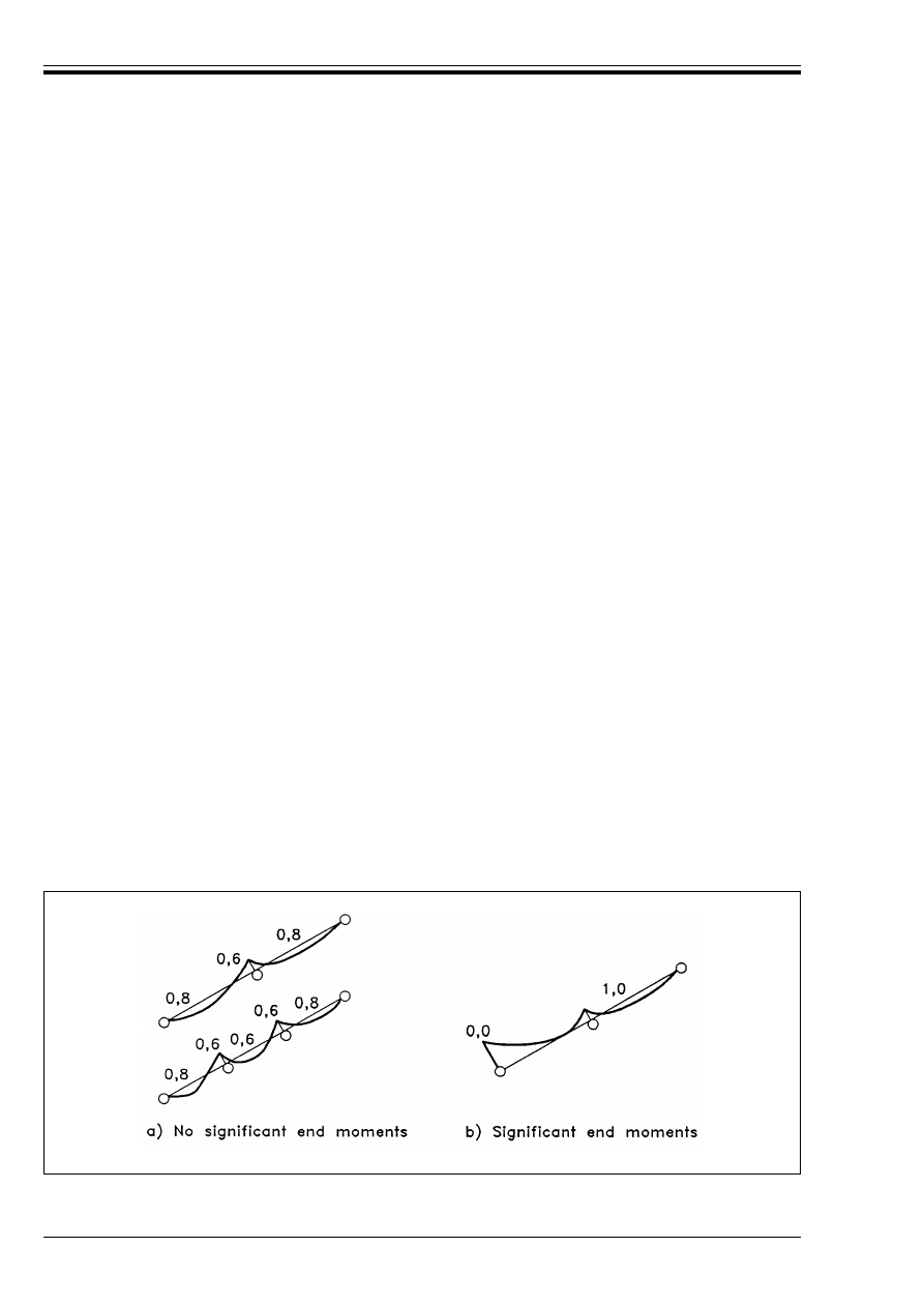
ENV 1995-1-1:1993
42
© BSI 02-2000
5.4.1.3
Simplified analysis
(1) As an alternative to a general analysis, a simplified analysis is permitted for fully triangulated trusses
which comply with the following conditions:
— there are no re-entrant angles in the external profile
— some part of the bearing width lies vertically below the support node (see Figure 5.4.1.1) or complies
with D.4(2)
— the truss height exceeds 0,15 times the span and 10 times the maximum chord depth
(2) The axial forces in the members should be determined assuming that every node is pin-jointed.
(3) The bending moments in single-bay members should also be determined on the basis that the end nodes
are pin-jointed. Bending moments in a member which is continuous over several bays should be determined
as if the member was a beam with a simple support at each node. The effect of deflection at the nodes and
partial fixity at the joints should be taken into account by a reduction of 10 % in the node bending moment.
The reduced node moments should be used to calculate the span bending moments.
5.4.1.4
Strength verification of members
(1) For elements in compression, the effective column length for in-plane strength verification should
generally be taken as the distance between two adjacent points of contraflexure.
(2) For fully triangulated trusses, the effective column length for
— members which are only one bay long without especially rigid end connections, and
— continuous members without lateral load
should be taken as the bay length.
(3) When a simplified analysis has been carried out, the following effective column lengths may be assumed
(see Figure 5.4.1.4).
— for continuous members with a lateral load but without significant end moments
— for continuous members with a lateral load and with signficiant end moments
For the strength verification of members in compression and connections, the calculated axial forces should
be increased by 10 %.
P(4) A check shall also be made that the lateral (out-of-plane) stability of the members is adequate.
— in an outer bay:
0, 8 times the bay length
— in an inner bay:
0,6 times the bay length
— at a node:
0,6 times the largest adjacent bay length.
— at the beam end with moment:
0 (i.e. no column effect)
— in the penultimate bay:
1,0 times bay length
— remaining bays and nodes:
as described above
Figure 5.4.1.4 — Effective column lengths
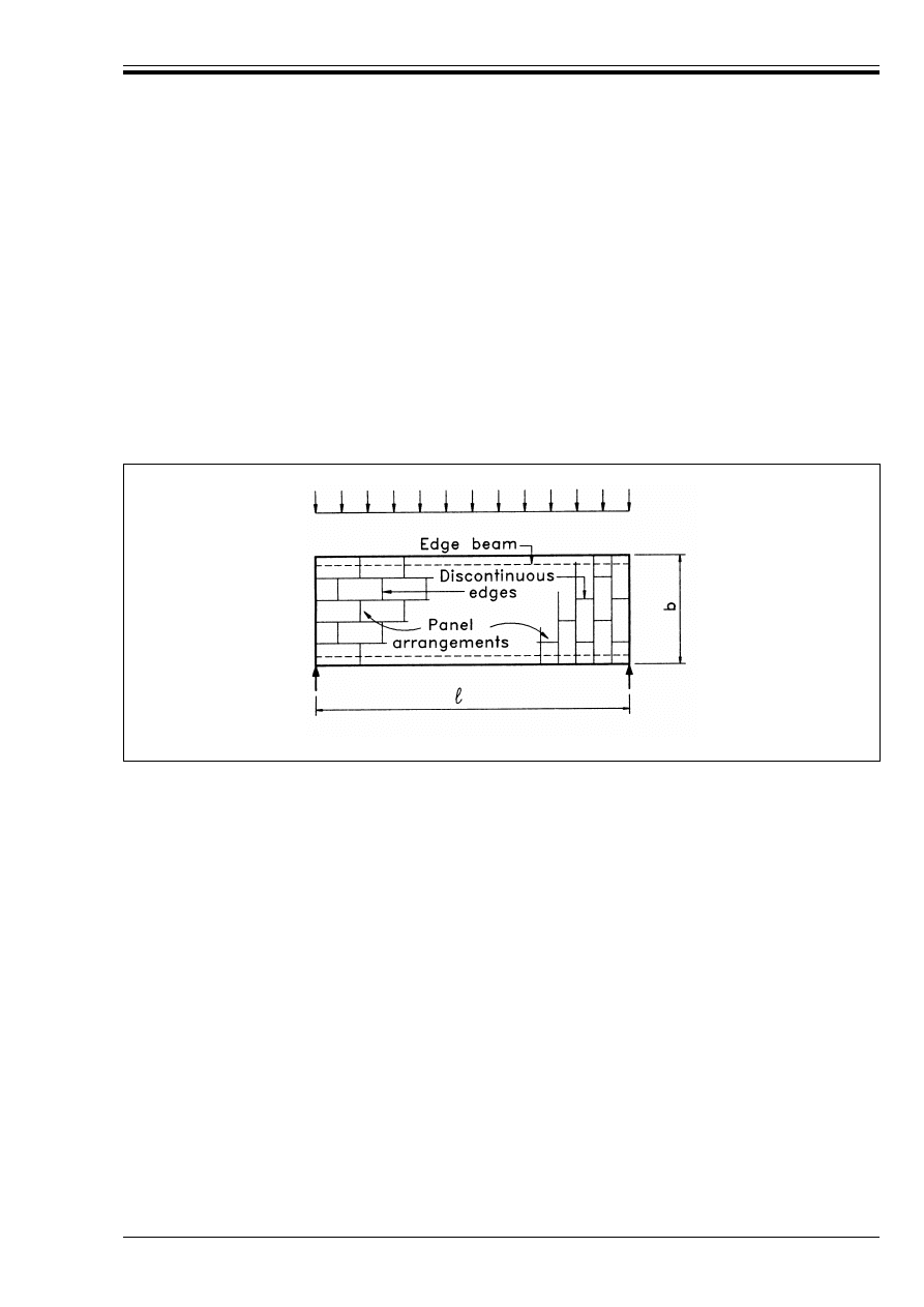
ENV 1995-1-1:1993
© BSI 02-2000
43
5.4.1.5
Trusses with punched metal plate fasteners
(1) Additional rules for trusses with punched metal plate fasteners are given in Annex D.
5.4.2 Roof and floor diaphragms
P(1) This section relates to the racking strength under wind action of horizontal diaphragms, such as floors
or roofs, assembled from sheets of wood-based material fixed by mechanical fasteners to a timber frame.
(2) The load-carrying capacity of fasteners at sheet edges may be increased by a factor of 1,2 over the values
given in chapter 6.
(3) For diaphragms with a uniformly distributed load (see Figure 5.4.2) the following simplified analysis
may be used provided:
— the span 1 lies between 2b and 6b, where b is the width
— the critical ultimate design condition is failure in the fasteners (and not in the panels) and
— the panels are fixed in accordance with the detailing rules in chapter 7.
(4) Unless a more detailed analysis is made, the edge beams should be designed to resist the maximum
bending moment in the diaphragm.
(5) The shear forces in the diaphragm may be assumed to be uniformly distributed over the width of the
diaphragm.
(6) When the sheets are staggered, (see Figure 5.4.2), the nail spacings along the discontinuous panel edges
may be increased by a factor of 1,5 (up to a maximum of 150 mm) without reduction of the load-carrying
capacity.
5.4.3 Wall diaphragms
P(1) This section relates to the racking strength of cantilevered wall diaphragms. The diaphragms consist
of framed panels made from sheets of board material fixed by mechanical fasteners to one or both sides of
a timber frame.
(2) The load carrying capacity F
k
(the racking resistance) under a force acting at the top of a cantilevered
panel secured against uplift (by vertical actions or by anchoring) should be determined by:
— calculations, or
— testing of prototype structures in accordance with prEN 594.
(3) The following simplified analysis may be used for a wall panel which consist of sheets fixed to one side
of a timber frame [see Figure 5.4.3(a)], provided that:
— there are no openings in excess of 200 mm square
— the fastener spacing is constant along the perimeter of every sheet
— b U h/4
Figure 5.4.2 — Diaphragm loading and staggered panel arrangements
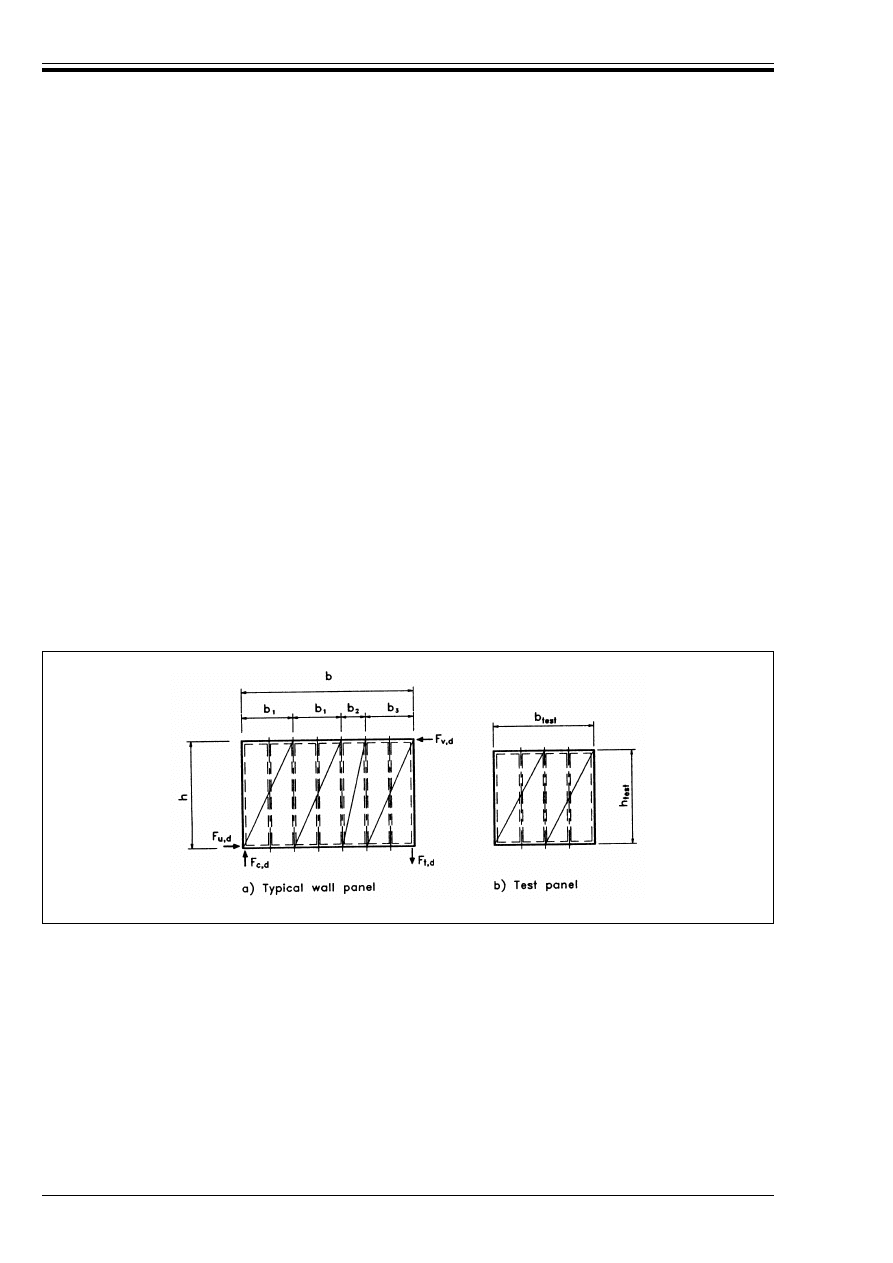
ENV 1995-1-1:1993
44
© BSI 02-2000
(4) The design racking load carrying capacity F
v,d
should be calculated as
where the symbols are defined as follows:
The design load-carrying capacity of fasteners along the edges of the panels may be increased by a factor
of 1,2 over the corresponding values given in chapter 6.
(5) If there are sheets on both sides of the panel, of the same type and thickness, the load-carrying capacity
may be taken as the sum of the calculated contributions. If the sheets or the fasteners are of different types
only half the load-carrying capacity of the weaker side should be taken.
(6) The compression studs should be designed for a force
(7) The tensile studs should be directly anchored to the substrate, and designed for a force F
d
, where
(8) If individual sheets within the diaphragm contain door or window openings, these sheets shall not be
assumed to contribute to the overall racking strength. Each group of adjacent solid sheets should be
anchored as an individual wall panel as shown in Figure 5.4.3c.
(9) If the characteristic strength of a test panel [see Figure 5.4.3 b)] has been determined, the strength of
a panel of similar construction, but with a different height h and width b, is given by
where
and
F
v,d
= CF
f,d
(b
i
/b
1
)
2
b
1
/s
(5.4.3a)
F
f,d
lateral design capacity per fastener
b
1
width of widest sheet
b
i
width of other sheets (b
2
,b
3
....)
s
spacing of the fasteners
F
d
=
0,67F
v,d
h/b
for sheets on both sides
(5.4.3b)
0,75F
v,d
h/b
for sheets on one side
(5.4.3c)
F
d
= F
v,d
h/b
(5.4.3d)
Figure 5.4.3 — Arrangement of a typical panel a) and a test panel b)
F
k
= k
b
k
h
F
test,k
(5.4.3e)
k
b
=
b/b
test
for b
test
k b
(5.4.3f)
(b/b
test
)
2
for 0,5b
test
k b < b
test
(5.4.3g)
0
for
b
k 0,5b
test
(5.4.3h)
k
h
=
h
test
/h)
2
for
h U h
test
(5.4.3j)
1
for
h < h
test
(5.4.3k)
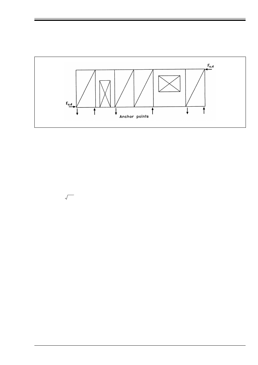
ENV 1995-1-1:1993
© BSI 02-2000
45
5.4.4 Plane frames
P(1) The stresses caused by geometrical and structural imperfections — i.e. deviations between the
geometrical axis and the elastic centre of the cross-section due to e.g. material inhomgenities — and
induced deflection shall be taken into account.
(2) This may be done by carrying out a second order linear analysis with the following assumptions:
— the imperfect shape of the structure should be assumed to correspond to an initial deformation which
is in approximate affinity to the relevant deformation figure, and found by applying an angle 8 of
inclination to the structure or relevant parts, together with an initial sinusoidal curvature between the
nodes of the structure corresponding to a maximum eccentricity e.
— the value of 8 in radians should as a minimum be taken as
where h is the height of the structure or the length of the member, in m.
— the value of e should as a minimum be taken as:
— the deflection should be calculated using a value of E of:
Examples of assumed initial deflections are given in Figure 5.4.4.
Figure 5.4.3c — Assembly of panels with openings
8 = 0,005
for h k 5m
(5.4.4a)
8 = 0,005
for h > 5m
(5.4.4b)
e = 0,003 1
(5.4.4c)
E = E
0,05
f
m,d
/f
m,k
(5.4.4d)
5/h
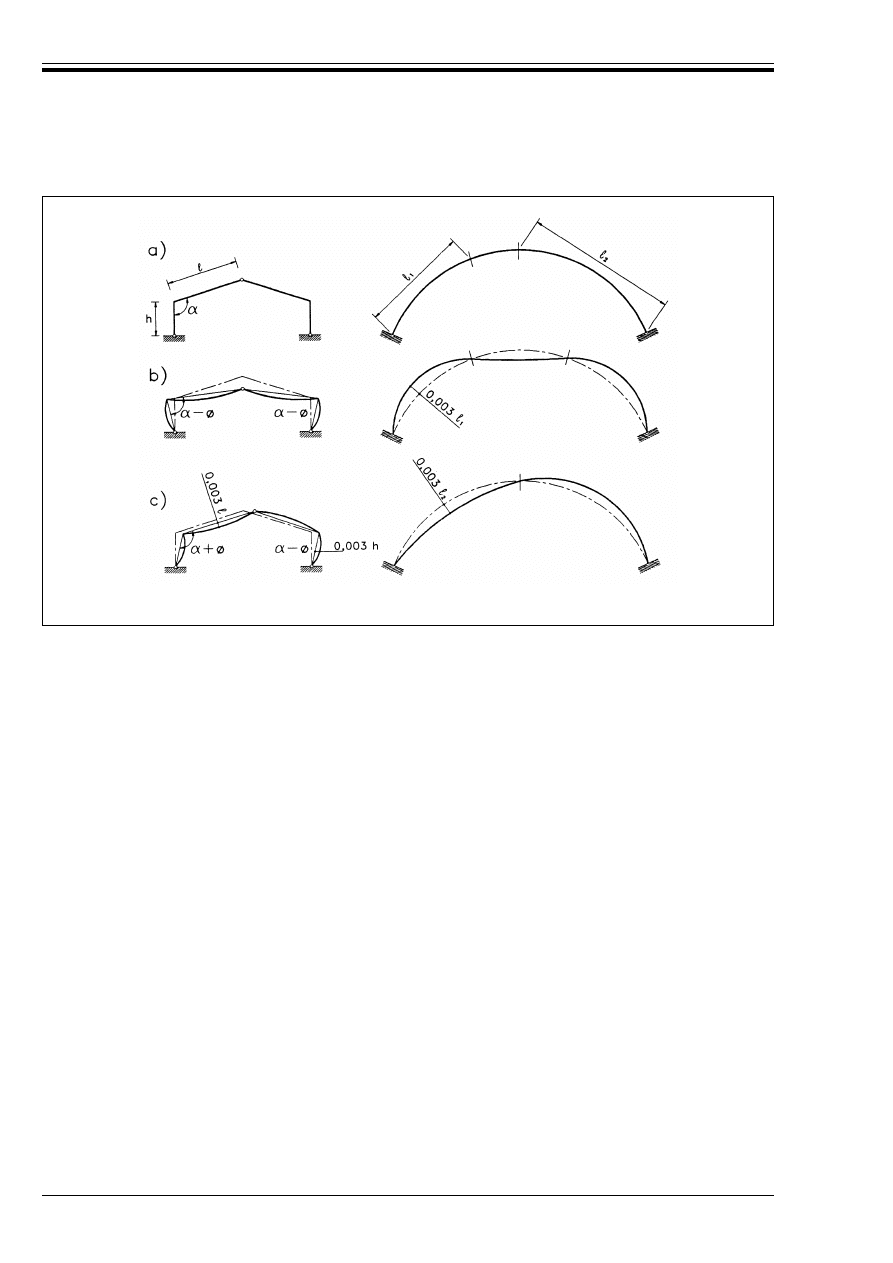
ENV 1995-1-1:1993
46
© BSI 02-2000
5.4.5 Bracing
5.4.5.1
General
P(1) Structures which are not otherwise adequately stiff shall be braced to prevent instability or excessive
deflection.
P(2) The stress caused by geometrical and structural imperfections, and by induced deflections (including
the contribution from any joint slip) shall be taken into account.
P(3) The bracing forces shall be determined on the basis of the most unfavourable combination of structural
imperfections and induced deflections.
5.4.5.2
Single members in compression
(1) For single elements in compression requiring lateral support at intervals (see Figure 5.4.5.2) the initial
deviations from straightness between supports should be within a/500 for glued laminated members, and
a/300 for other members.
(2) Each intermediate support should have a minimum spring stiffness C, given by
where
and m is the number of bays each of length a.
(3) The design stabilising force F
d
at each support should as a minimum be taken as:
where N
d
is the mean design compressive force in the element.
Figure 5.4.4 — Examples of assumed initial deflections for a frame a), corresponding to a
symmetrical load b) and non-symmetrical load c)
C = k
s
;
2
EI/a
3
(5.4.5.2a)
E = E
0,05
f
m,d
/f
m,k
(5.4.5.2b)
k
s
= 2(1 + cos ;/m)
(5.4.5.2c)
F
d
= N
d
/50
for solid timber;
(5.4.5.2d)
F
d
= N
d
/80
for glued laminated timber;
(5.4.5.2e)
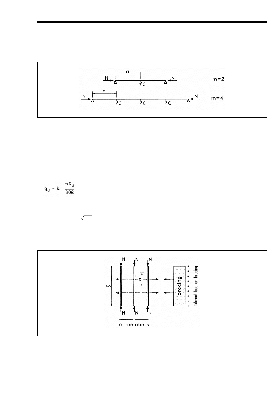
ENV 1995-1-1:1993
© BSI 02-2000
47
(4) The design stabilising force F
d
for the compression flange of a rectangular beam should be determined
in accordance with 5.4.5.2(3), where
The value of k
crit
should be determined from 5.2.2(4) for the unbraced beam. M
d
is the maximum design
moment in the beam of depth h.
5.4.5.3
Bracing of beam or truss systems
(1) For a series of n parallel members which require lateral supports at intermediate nodes A,B, etc.
(see Figure 5.4.5.3) a bracing system should be provided, which, in addition to the effects of a horizontal
load should be capable of resisting a load per unit length q, where
and where
N
d
is mean design axial compression force in the member, of overall length =m.
(2) The horizontal deflection at midspan due to q
d
acting alone should not exceed =/700.
(3) The horizontal deflection due to q
d
and any other load should not exceed =/500.
5.4.6 Load sharing
(1) When an assembly of several equally spaced similar members is laterally connected by a continuous
load-distribution system, the member design strengths may be multiplied by a load sharing factor k
ls
.
Figure 5.4.5.2 — Examples of single members in compression braced by lateral supports
N
d
= (1 – k
crit
) M
d
/h
(5.4.5.2f)
(5.4.5.3a)
k
=
= min.
1
(5.4.5.3b)
(5.4.5.3c)
Figure 5.4.5.3 — Beam or truss system requiring lateral supports
15/=

ENV 1995-1-1:1993
48
© BSI 02-2000
(2) Unless a more detailed analysis is made, a value of k
ls
= 1,1 may be assumed for the assemblies and
load-distribution systems described in Table 5.4.6 if the following requirements are fulfilled:
— the load-distribution system is designed to support the applied permanent and variable loads
— each element of the load-distribution system is continuous over at least two spans, and any joints are
staggered.
Table 5.4.6 — Description of assemblies and load-distribution systems
6 Joints
6.1 General
P(1) The characteristic load-carrying capacities and deformation characteristics of fasteners shall be
determined on the basis of tests carried out in conformity with EN 26891, EN 28970, and the relevant
European test standards unless design rules are given below. In cases where both compressive and tensile
tests are described in the relevant standards, the tensile test shall be used.
P(2) It shall be taken into account that the characteristic load-carrying capacity of a multiple-fastener joint
will frequently be less than the sum of the individual fastener capacities.
P(3) If the load at a joint is transferred by more than one type of fastener, account shall be taken of the
effect of the different fastener properties
24)
.
P(4) It shall be taken into account that the characteristic load-carrying capacity of a joint will frequently
be reduced if it is subject to reversal of load from long- and medium-term actions.
(5) The effect on joint strength of long-term and medium-term actions alternating between tension F
t
and
compression F
c
in the members should be taken into account by designing the joint for F
t,d
+ 0,5F
c,d
and
F
c,d
+ 0,5F
t,d
.
P(6) The arrangement and sizes of the fasteners in a joint, and the fastener spacings, edge and end
distances shall be chosen so that the expected strengths can be obtained.
P(7) When the force in the joint acts at an angle to the grain the influence of the tension stresses
perpendicular to the grain shall be taken into account.
(8) Unless a more detailed calculation is made, for the arrangement shown in Figure 6.1 it should be shown
that the following condition is satisfied:
provided that b
e
> 0,5h. The symbols are defined as follows:
Assembly
Load-distribution system
Flat roof or floor joists (maximum span 6 m)
Roof trusses (maximum span 12 m)
Rafters (maximum span 6 m)
Wall studs (maximum height 4 m)
Boards or sheathing
Tiling battens, purlins or sheathing
Tiling battens or sheathing
Head and sole plates, sheathing at least one side.
24)
Glue and mechanical fasteners have very different stiffness properties and should not be assumed to act in unison.
V
d
k 2 f
v,d
b
e
t/3
(6.1a)
V
d
design shear force produced in the member of thickness t by the fasteners or connectors
(V
1
+ V
2
= Fsin !)
b
e
distance from the loaded edge to the furthest fastener or connector
!
angle between force F and grain direction.
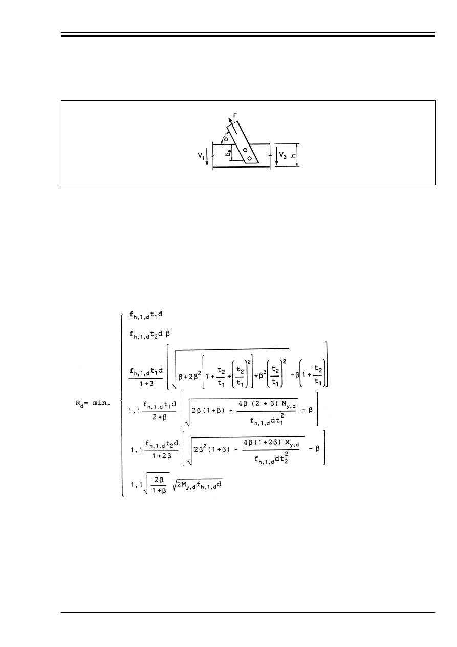
ENV 1995-1-1:1993
© BSI 02-2000
49
(9) For dowel-type fasteners the instantaneous slip modulus K
u
per shear plane per fastener for ultimate
limit state design should be taken as
Values of K
ser
are given in Table 4.2.
6.2 Lateral load-carrying capacity of dowel-type fasteners
6.2.1 Timber-to-timber and panel-to-timber joints
(1) The design load-carrying capacity per shear plane per fastener, for timber-to-timber and
panel-to-timber joints made with fasteners covered in sections 6.3 to 6.7 should be taken as the smallest
value found from the following formulae:
Design load-carrying capacities for fasteners in single shear:
Figure 6.1 — Joint force acting at an angle to the grain
K
u
= 2K
ser
/3
(6.1b)
(6.2.1a)
(6.2.1b)
(6.2.1c)
(6.2.1d)
(6.2.1e)
(6.2.1f)
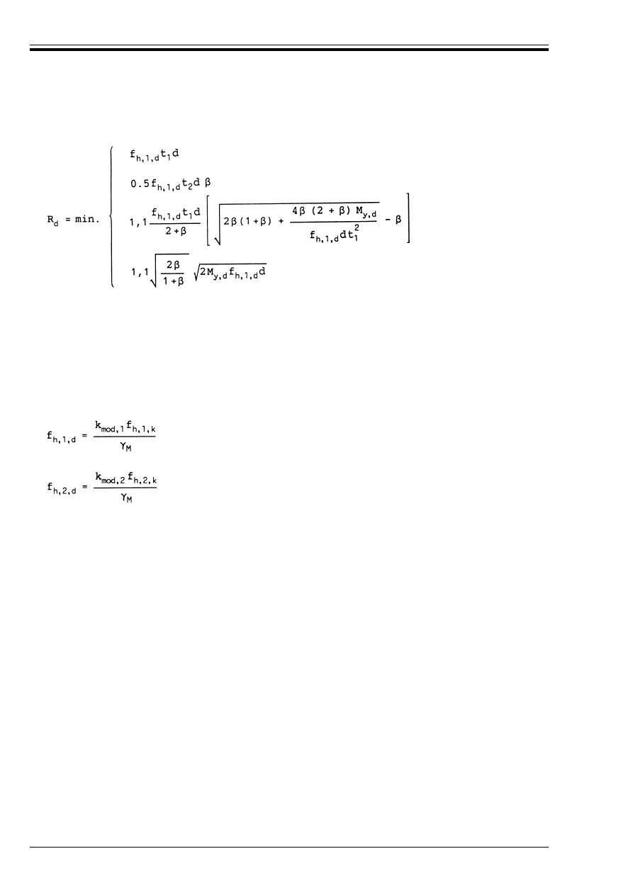
ENV 1995-1-1:1993
50
© BSI 02-2000
Design load-carrying capacities for fasteners in double shear:
The various failure modes are illustrated in Figure 6.2.1. The symbols are defined as follows:
(2) The design values of the embedding strengths, f
h,l,d
or f
h,2,d,
respectively, should be calculated as:
Values of the modification factor k
mod
are given in Table 3.1.7, and the values of *
M
are given in
Table 2.3.3.2.
(3) The design value of the fastener yield moment M
y,d
should be calculated as:
where *
M
is given in Table 2.3.3.2.
(4) The embedding strength f
h
should be determined in accordance with prEN 383 and Annex A, unless
specified in the following clauses.
(6.2.1g)
(6.2.1h)
(6.2.1j)
(6.2.1k)
t
1
and t
2
timber or board thickness or penetration. (See also sections 6.3 to 6.7).
f
h,l,d
(f
h,2,d
)
design embedding strength in t
1
(t
2
)
"
f
h,2,d
/f
h,1,d
d
fastener diameter
M
y,d
fastener design yield moment
(6.2.1l)
(6.2.1m)
(6.2.1n)
M
y,d
M
y,k
*
M
------------
=
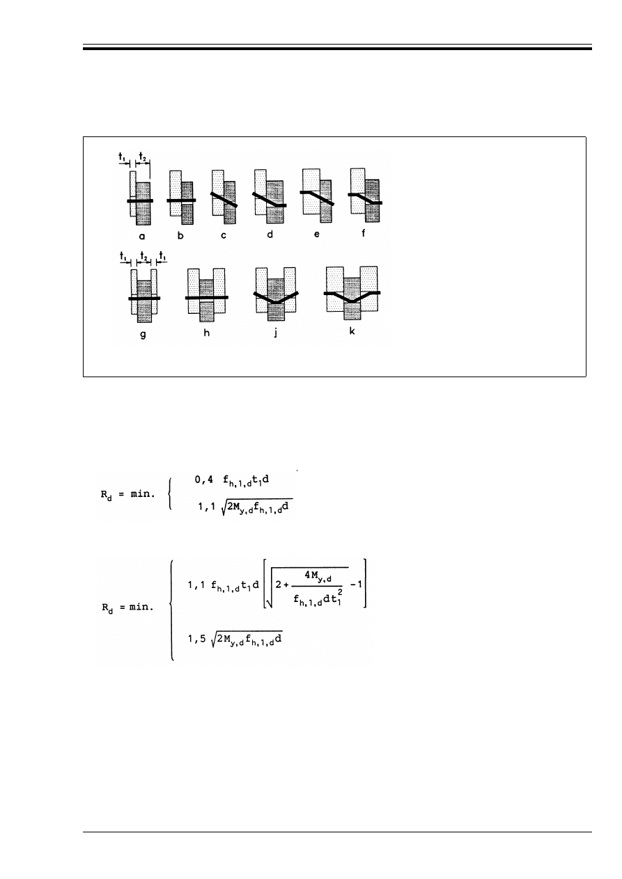
ENV 1995-1-1:1993
© BSI 02-2000
51
(5) The yield moment M
y
should be determined in accordance with prEN 409 and Annex A, unless specified
in the following clauses.
6.2.2 Steel-to-timber joints
(1) The design load-carrying capacity per fastener for single shear steel-to-timber joints, for a thin steel
plate (i.e. for t k 0,5d where t is the thickness), should be taken as the smaller value found from the
following formulae:
For a thick steel plate (i.e. for t U d), the design load-carrying capacity should be taken as the smaller value
found from the following formulae:
For 0,5d < t < d linear interpolation is permitted.
The symbols are defined in 6.2.1(1), and the failure modes are illustrated in Figure 6.2.2a–d.
Single shear
Double shear
(The letters correspond to the relevant formula reference)
Figure 6.2.1 — Failure modes for timber and panel joints
(6.2.2a)
(6.2.2b)
(6.2.2c)
(6.2.2d)
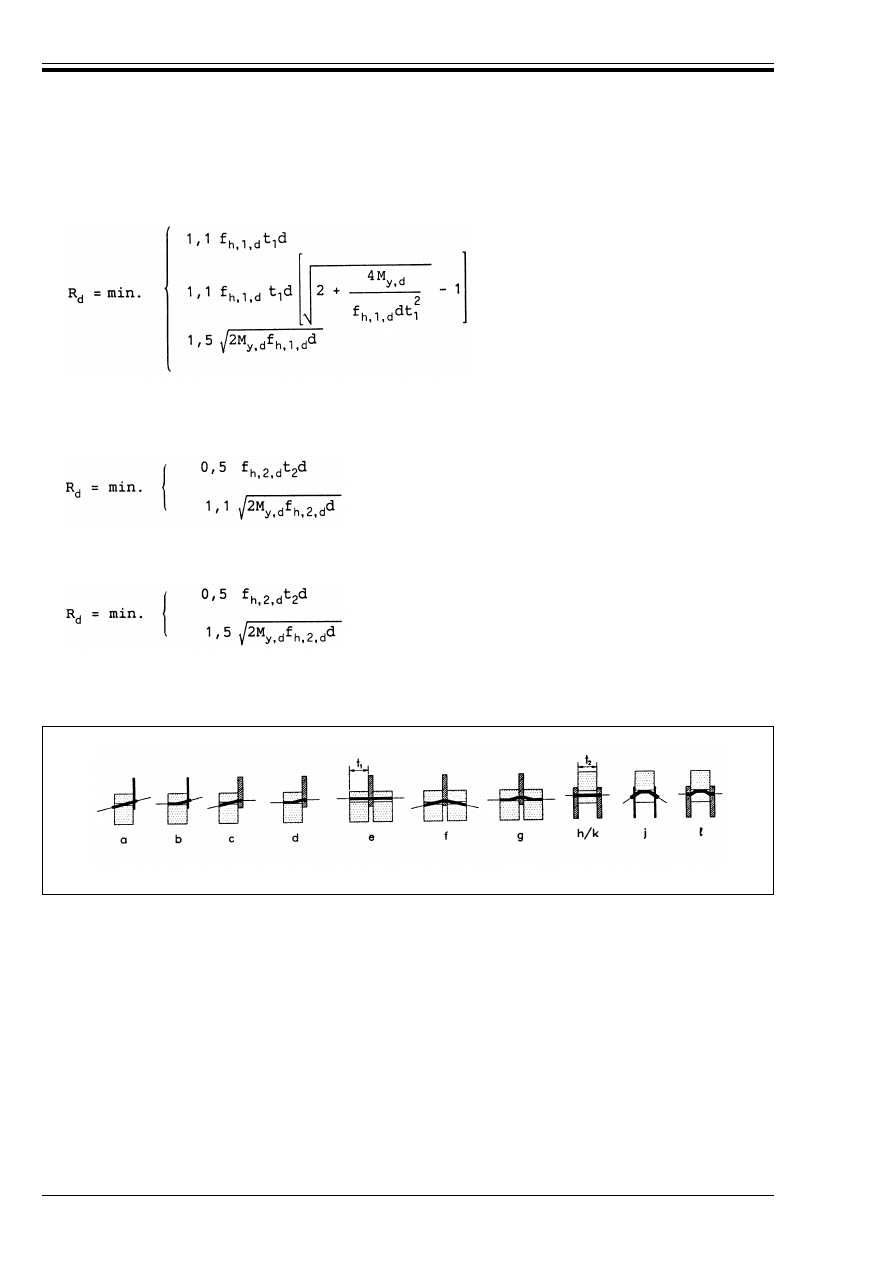
ENV 1995-1-1:1993
52
© BSI 02-2000
(2) The design load-carrying capacity per shear plane per fastener for double shear joints with the centre
member of steel should be taken as the smallest value found from the following formulae:
where the symbols are defined in 6.2.1(1), and the failure modes are illustrated in Figure 6.2.2e–g.
(3) The design load-carrying capacity per shear plane per fastener for double shear joints with both outer
members of thin steel should be taken as the smaller value found from the following formulae:
(4) For thick steel plates (i.e. for t U d), the design load-carrying capacity should be taken as the smaller
value found from the following formulae:
For 0,5d < t < d linear interpolation is permitted.
The symbols are defined in 6.2.1(1), and the failure modes are illustrated in Figure 6.2.2h–l.
(5) A check should also be made on the strength of the steel plate.
6.2.3 Multiple shear joints
(1) In multiple shear joints the total load-carrying capacity should be determined by calculating the sum of
the lowest load-carrying capacities for each shear plane, taking each shear plane as part of a series of
three-member joints.
6.3 Nailed joints
6.3.1 Laterally loaded nails
6.3.1.1
General
(1) The rules in 6.2 apply, with the symbols defined as follows:
(6.2.2e)
(6.2.2f)
(6.2.2g)
(6.2.2h)
(6.2.2j)
(6.2.2k)
(6.2.2l)
Figure 6.2.2 a–l — Failure modes for steel-to-timber joints
t
1
(for double shear joints) the lesser of the headside timber thickness and the pointside penetration
(see Figure 6.3.1.1)
t
2
pointside penetration for single shear joints and central thickness for double shear joints.
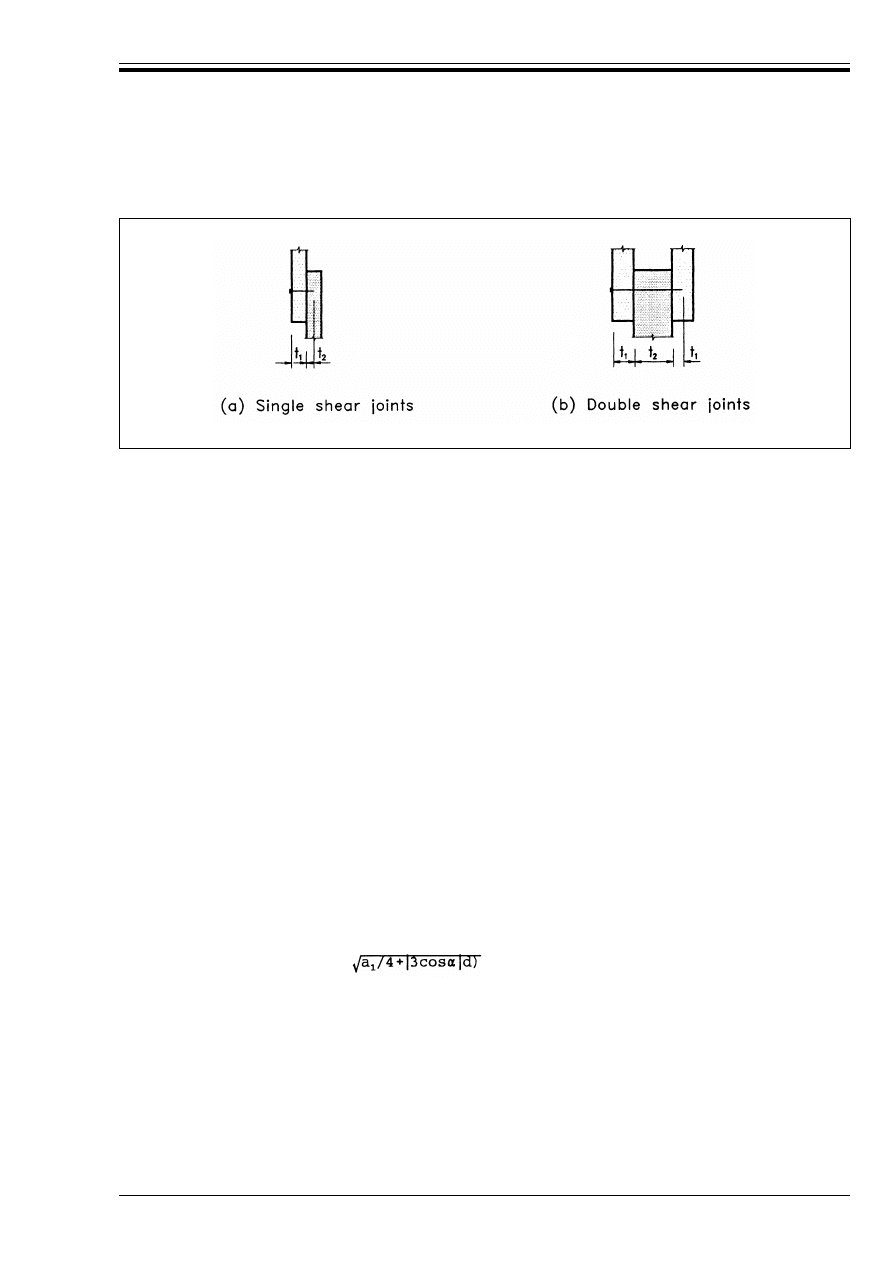
ENV 1995-1-1:1993
© BSI 02-2000
53
(2) For square nails d should be taken as the side dimension.
6.3.1.2
Nailed timber-to-timber joints
(1) The following characteristic embedding strength values should be used for nails up to 8 mm, for all
angles to the grain:
with @
k
in kg/m
3
and d in mm.
(2) For common smooth steel wire nails with a minimum tensile strength of the wire from which the nails
are produced of 600 N/mm
2
, the following characteristic values for yield moment should be used:
for round nails, and
for square nails, with d in mm.
(3) Holes should be pre-drilled for nails in timber with a characteristic density of 500 kg/m
3
or more.
(4) For smooth nails the pointside penetration length should be at least 8d.
(5) For annular ringed shank and helically threaded nails the pointside penetration length should be at
least 6d.
(6) There should normally be at least two nails in a joint.
(7) Nails in end grain should normally not be considered capable of transmitting force. Where nails in end
grain are used in secondary structures, e.g. for fascia boards nailed to rafters, the design value should be
taken as 1/3 of the value for normal nailing.
(8) Minimum spacings and distances are given in Table 6.3.1.2, with the definitions given in
Figure 6.3.1.2a.
(9) For nails in predrilled holes the spacing a
1
may be reduced to a minimum of 4d, if the embedding
strength is reduced by the factor .
Figure 6.3.1.1 (a) and (b) — Definitions of t
1
and t
2
— without predrilled holes
f
h,k
= 0,082@
k
d
–0,3
N/mm
2
(6.3.1.2a)
— with predrilled holes
f
h,k
= 0,082(1 – 0,01d) @
k
N/mm
2
(6.3.1.2b)
M
y,k
= 180d
2,6
Nmm
(6.3.1.2c)
M
y,k
= 270d
2,6
Nmm
(6.3.1.2d)
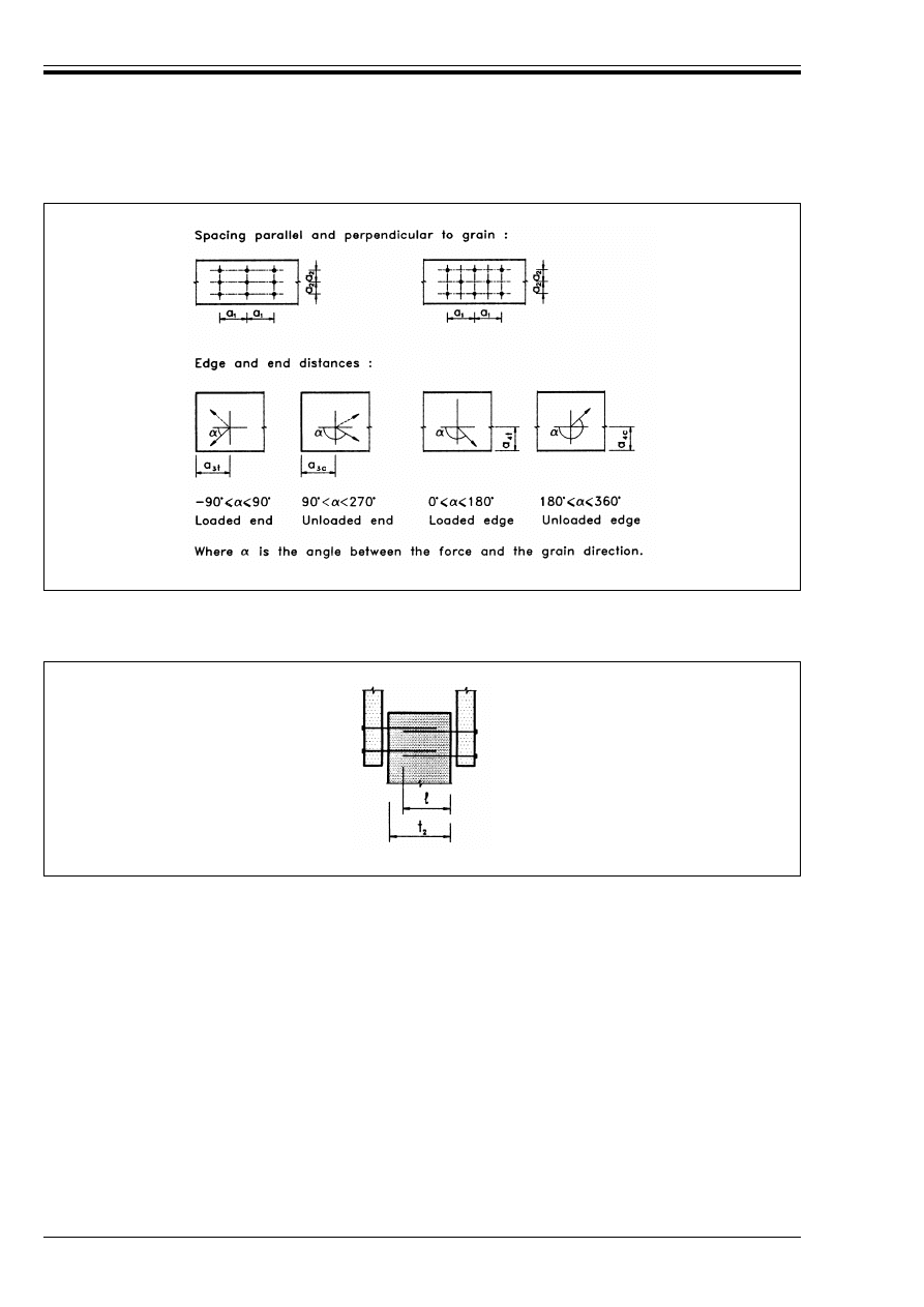
ENV 1995-1-1:1993
54
© BSI 02-2000
(10) If (t
2
– =) is greater than 4d (see Figure 6.3.1.2b) then nails without predrilled holes driven from two
sides may overlap in the middle member.
(11) For nails without predrilled holes the timber members should have a minimum thickness of t, where
with @
k
in kg/m
3
and d in mm.
Figure 6.3.1.2a — Fastener spacings and distances — definitions
Figure 6.3.1.2b — Overlapping nails
t = max.
7d
(6.3.1.2e)
(13d – 30)@
k
/400
(6.3.1.2f)
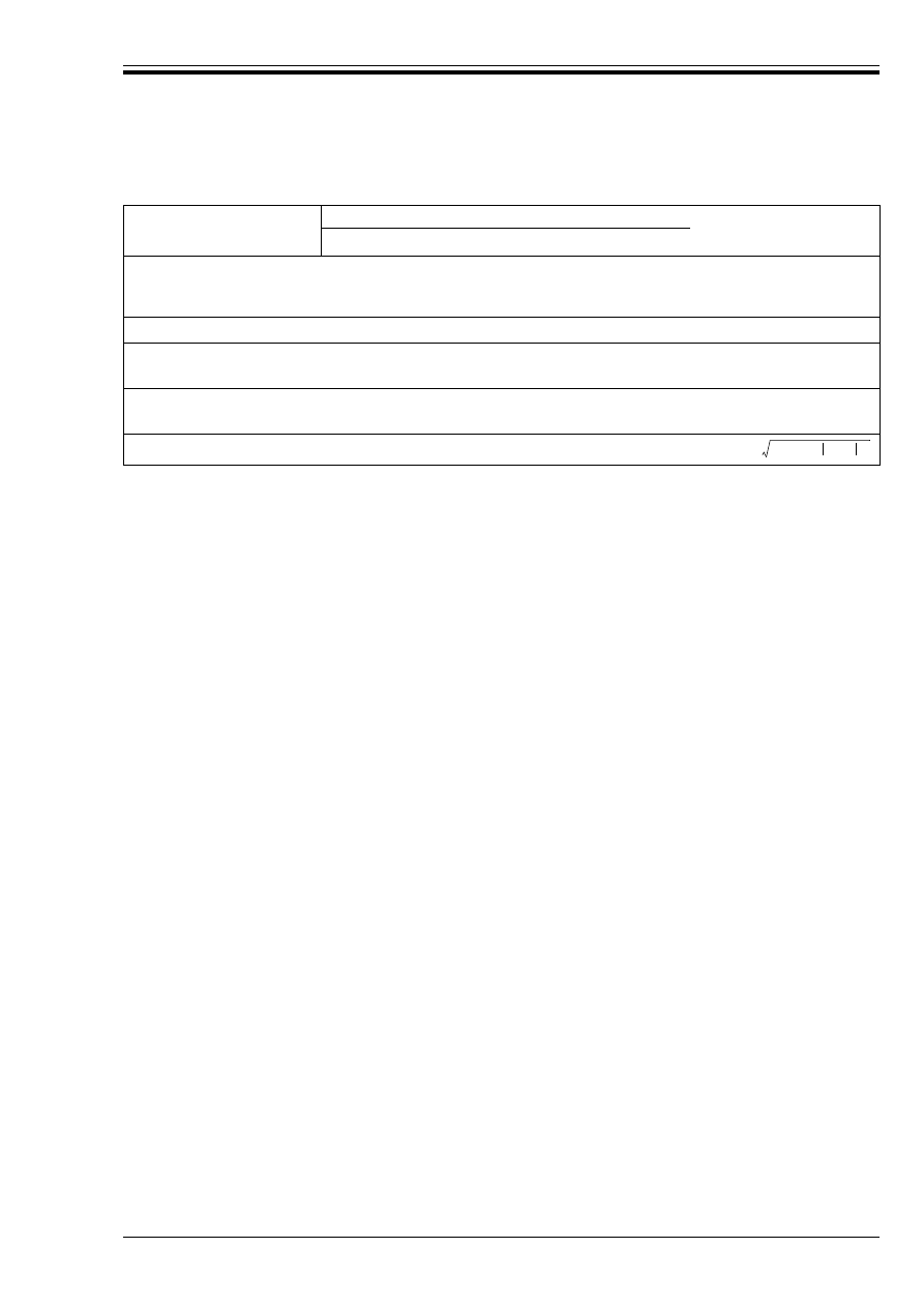
ENV 1995-1-1:1993
© BSI 02-2000
55
Table 6.3.1.2 — Minimum nail spacings and distances — values
6.3.1.3
Nailed panel-to-timber joints
(1) The rules for timber-to-timber joints apply. Design values of the panel embedding strengths should be
calculated as shown in 6.2.1(2).
(2) For plywood the following values of characteristic embedding strengths should be used:
with @
k
in kg/m
3
and d in mm.
(3) For hardboard the following values of characteristic embedding strengths should be used:
with d and t in mm (t = panel thickness).
(4) The rules apply to ordinary nails with heads which have a diameter of at least 2d. For smaller heads
the design load-carrying capacity should be reduced; for pins and oval headed nails, for example, the design
load-carrying capacity in particleboards and fibreboards should be reduced by half.
(5) Minimum nail spacings for plywood in plywood-to-timber joints are those given in Table 6.3.1.2,
multiplied by a factor of 0.85.
(6) The minimum distances in the plywood should be taken as 3d for an unloaded edge (or end)
and (3 + 4sin!) d for a loaded edge (or end).
6.3.1.4
Nailed steel-to-timber joints
(1) The rules in 6.2.2 apply.
(2) Minimum nail spacings are those given in Table 6.3.1.2, multiplied by a factor of 0.7.
6.3.2 Axially loaded nails
P(1) Axially loaded smooth nails shall not be used for permanent and long-term load.
(2) The design withdrawal capacity of nails for nailing perpendicular to the grain [as in Figure 6.3.2(a)] and
for slant nailing [as in Figure 6.3.2(b)] should be taken as the smallest of the values according to
formula 6.3.2a (corresponding to withdrawal of the nail in the member receiving the point), and
formulae 6.3.2b and c (corresponding to the head being pulled through). For smooth nails with a head
diameter of at least 2d, formula 6.3.2b may be disregarded.
The pointside penetration 1 should as a minimum be taken as 12d for smooth nails and as 8d for other
nails.
Spacings and
distances
(see Figure 6.3.1.2a)
Without predrilled holes
Predrilled holes
@
k
k420 kg/m
3
420 < @
k
< 500 kg/m
3
a
1
d < 5 mm: (5 + 5|cos!|)d
(7 + 8|cos!|)d
d U 5 mm: (5 + 7|cos!|)d
(4 + 3|cos!|)d
a
a
2
5d
5d
(3 + |sin!|)d
a
3t
(loaded end)
a
3c
(unloaded end)
(10 + 5cos!)d
10d
(15 + 5cos!)d
15d
(7 + 5cos!)d
7d
a
4,t
(loaded edge)
a
4,c
(unloaded edge)
(5 + 5sin!)d
5d
(7 + 5sin!) d
7d
(3 + 4sin!)d
3d
a
The minimum spacing a
1
may be further reduced to 4d if the embedding strength f
h,k
is reduced by the factor
f
h,k
= 0.11@
k
d
–0.3
N/mm
2
(6.3.1.3a)
f
h,k
= 30d
–0,3
t
0,6
N/mm
2
(6.3.1.3b)
R
1
= min
f
1,d
dl
for all nails
(6.3.2a)
f
1,d
dh + f
2,d
d
2
for smooth nails
(6.3.2b)
f
2,d
d
2
for annular ringed shank and threaded nails
(6.3.2c)
a
1
/
4 3 cos !
+
(
)
d
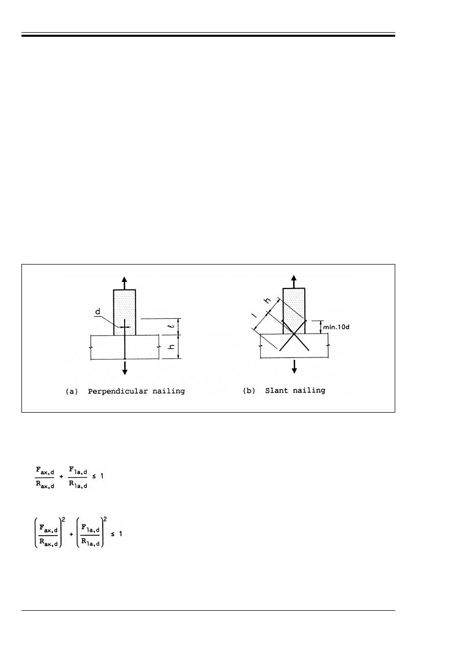
ENV 1995-1-1:1993
56
© BSI 02-2000
(3) The parameters f
1
and f
2
depend, among other things, on the type of nail, timber species and grade
(especially density) and should be determined by tests in accordance with the relevant European test
standards unless specified in the following clause.
(4) The design values of the parameters f
1
and f
2
should be calculated as shown in 6.2.1(2).
(5) For smooth round nails the following characteristics values should be used:
with @
k
in kg/m
3
.
(6) For structural timber which is installed at or near fibre saturation point, and which is likely to dry out
under load, the values of f
1,k
and f
2,k
should be multiplied by 2/3.
(7) Nails in end grain should normally be considered incapable of transmitting axial load.
(8) For annular ring shanked and helically threaded nails only the threaded part should be considered
capable of transmitting axial load.
(9) The spacings and distances for axially loaded nails should be the same as for laterally loaded nails. For
slant nailing the distance to the loaded edge should be at least 10d [see Figure 6.3.2(b)].
6.3.3 Combined laterally and axially loaded nails
(1) For joints with a combination of axial load (F
ax
) and lateral load (F
la
) the following conditions should be
satisfied:
for smooth nails
for annular ringed shank and helically threaded nails
where R
ax,d
and R
la,d
are the design load-carrying capacities of the joint loaded with axial load or lateral
load alone.
f
l,k
= (18 × 10
–6
) @k
2
N/mm
2
(6.3.2d)
f
2,k
= (300 × 10
–6
) @k
2
N/mm
2
(6.3.2e)
Figure 6.3.2 (a) and (b) — Perpendicular and slant nailing
(6.3.3a)
(6.3.3b)
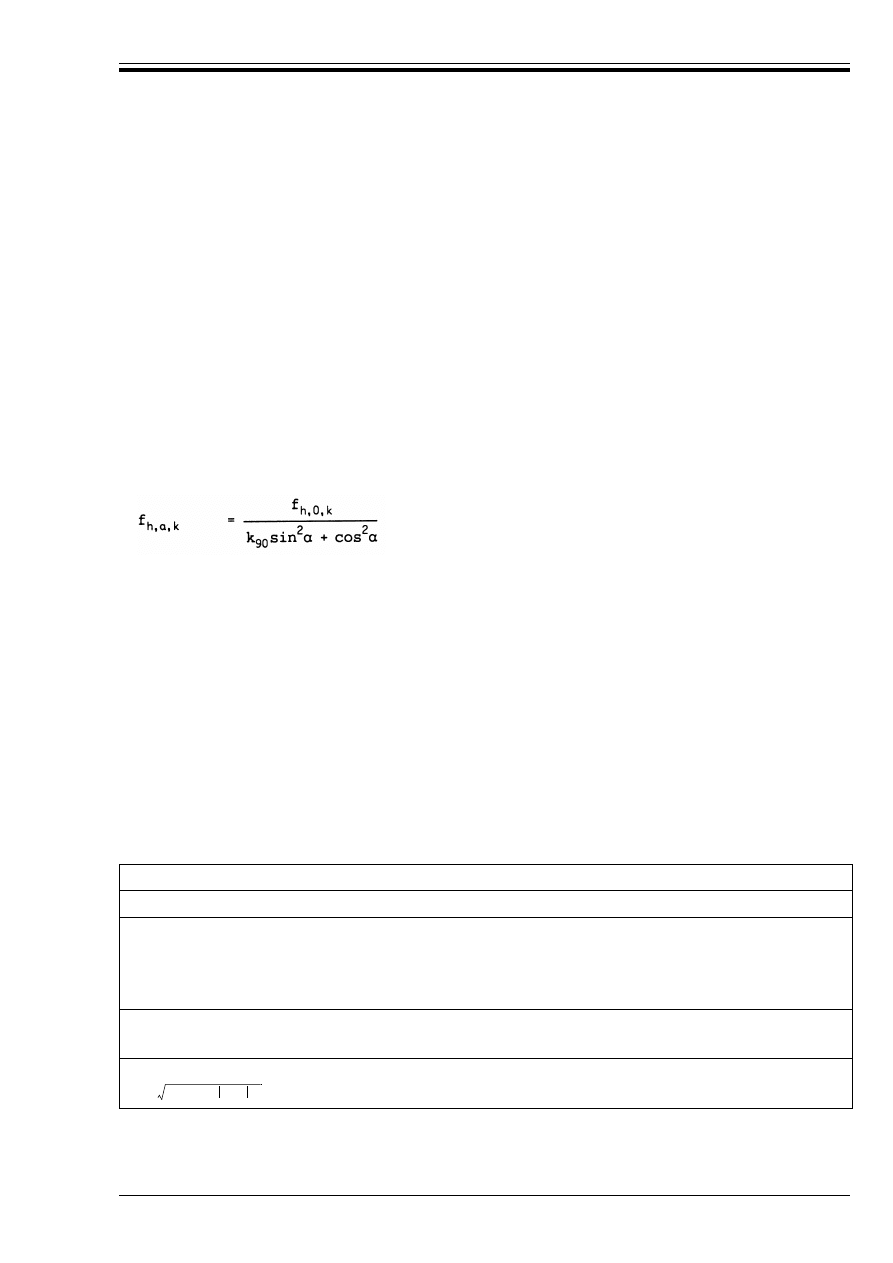
ENV 1995-1-1:1993
© BSI 02-2000
57
6.4 Stapled joints
(1) The rules for nailed joints apply.
(2) The lateral design load-carrying capacity should be considered as equivalent to that of two nails with
the staple diameter, provided that the angle between the crown and the direction of the grain of the timber
under the crown is greater than 30°.
(3) If the angle between the crown and the direction of the grain under the crown is equal to or less than 30°,
then the lateral design load-carrying capacity should be multiplied by a factor of 0.7.
6.5 Bolted joints
6.5.1 Laterally loaded bolts
6.5.1.1
General
(1) The rules given in 6.2 apply.
6.5.1.2
Bolted timber-to-timber joints
(1) For bolts up to 30 mm diameter the following characteristic embedding strength values should be used,
at an angle ! to the grain:
with @
k
in kg/m
3
and d in mm.
(2) For round steel bolts the following characteristic value for the yield moment should be used:
where f
u,k
is the characteristic tensile strength.
(3) For more than 6 bolts in line with the load direction, the load carrying capacity of the extra bolts should
be reduced by 1/3, i.e. for n bolts the effective number n
ef
is
(4) Minimum spacings and distances are given in Table 6.5.1.2. The symbols are as defined in
Figure 6.3.1.2a.
Table 6.5.1.2 — Minimum spacings and distances for bolts
6.5.1.3
Bolted panel-to-timber joints
(1) The rules for timber-to-timber joints apply. Design values of the panel embedding strengths should be
calculated as shown in 6.2.1(2).
(6.5.1.2a)
f
h,0,k
= 0,082 (1 – 0,01d) @
k
N/mm
2
(6.5.1.2b)
k
90
= 1,35 + 0,015d for softwoods
(6.5.1.2c)
k
90
= 0,90 + 0,015d for hardwoods
(6.5.1.2d)
M
y,k
= 0,8f
u,k
d
3
/6
(6.5.1.2e)
n
ef
= 6 + 2(n – 6)/3
(6.5.1.2f)
a
1
Parallel to the grain
(4 + 3|cos!|)d
a
a
2
Perpendicular to the grain
4d
a
3,t
a
3,c
– 90° k ! k 90°
150° k ! k 210°
Ð90°
k ! k 150°
210° < ! < 270°
7d (but not less than 80 mm)
4d
(1 + 6|sin !|)d (but not less than 4d)
a
4,t
a
4,c
0° k ! k 180°
all other values of !
(2 + 2sin!)d (but not less than 3d)
3d
a
The minimum spacing a
1
may be further reduced to 4d if the embedding strength f
h,0,k
is reduced by the
factor
.
a
1
4 3 cos!
+
(
)
d
⁄

ENV 1995-1-1:1993
58
© BSI 02-2000
(2) For plywood the following embedding strength value should be used at all angles to the face grain:
with @
k
in kg/m
3
and d in mm.
6.5.1.4
Bolted steel-to-timber joints
(1) The rules given in 6.2.2 and 6.5.1.1 apply.
6.5.2 Axially loaded bolts
P(1) A check shall be made of the adequacy of the bolt tensile strength and washer thickness.
(2) The design compressive stress under the washer should not exceed 1,8f
c,90,d
.
6.6 Dowelled joints
(1) The rules for laterally loaded bolts apply, with the exception of 6.5.1.2(4).
(2) Minimum spacings and distances are given in Table 6.6a. The symbols are defined in Figure 6.3.1.2a
Table 6.6a — Minimum spacings and distances for dowels
6.7 Screwed joints
6.7.1 Laterally loaded screws
(1) For screws with a diameter less than 8 mm the rules in 6.3.1 apply.
For screws with a diameter equal to or greater than 8 mm the rules in 6.5.1 apply.
In the relevant formulae d should be taken as the diameter in mm of the screw measured on the smooth
shank. To calculate the value of M
y,k
an effective diameter of d
ef
= 0,9d should be used, provided that the
root diameter of the screw is not less than 0,7d.
If the length of the smooth shank in the pointside member is not less than 4d, the shank diameter may be
used to calculate the value of M
y,k
.
(2) It is assumed that:
— screws are turned into pre-drilled holes (see section 7.4)
— the length of the smooth shank is greater than or equal to the thickness of the member under the
screw head.
(3) The penetration depth of the screw (i.e. the length in the member receiving the point), should be at
least 4d.
6.7.2 Axially loaded screws
(1) The design withdrawal capacity of screws driven at right angles to the grain should be taken as:
where the symbols are defined as follows:
f
h,k
= 0,11(1 – 0,01d) @
k
N/mm
2
(6.5.1.3)
a
1
Parallel to the grain
(3 + 4|cos!|)d
a
a
2
Perpendicular to the grain
3d
a
3,t
a
3,c
– 90° k ! k 90°
150° < ! < 210°
90° ! < 150°
210° < ! < 270°
7d (but not less than 80 mm)
3d
a
3,t
|sin!| (but not less than 3d)
a
4,t
a
4,c
0° k ! k180°
all other values of !
(2 + 2sin!)d (but not less than 3d)
3d
a
The minimum spacing may be further reduced to 4d if the embedding strength f
h,0,k
is reduced by the factor
.
R
d
= f
3,d
(l
ef
– d) N
(6.7.2a)
f
3,d
design withdrawal parameter
l
ef
threaded length in mm in the member receiving the screw
a
1
4 3 cos !
+
(
)
d
⁄

ENV 1995-1-1:1993
© BSI 02-2000
59
The design withdrawal parameter f
3,d
should be calculated from the characteristic withdrawal parameter
f
3,k
as shown in 6.2.1(2).
The characteristic value of f
3,k
should be taken as
with @
k
in kg/m
3
The minimum distances and penetration length should be as given for laterally loaded screws.
6.7.3 Combined laterally and axially loaded screws
(1) The condition given in equation (6.3.3b) should be satisfied.
6.8 Joints made with punched metal plate fasteners
(1) For joints made with punched metal plate fasteners the rules given in Annex Dapply.
7 Structural detailing and control
7.1 General
P(1) Timber structures shall be so constructed that they conform with the principles of the design.
Materials for the structures shall be applied, used or fixed in such a way as to perform adequately the
functions for which they are designed.
P(2) Workmanship in fabrication, preparation and installation of materials shall conform to accepted good
practice.
7.2 Materials
P(1) The deviation from straightness measured midway between the supports shall for columns and beams
where lateral instability can occur and members in frames be limited to 1/500 of the length for glued
laminated members and to 1/300 of the length for structural timber
25)
.
(2) Timber and wood-based components and structural elements should not be unnecessarily exposed to
climatic conditions more severe than those to be encountered in the finished structure.
(3) Before construction timber should be dried as near as practicable to the moisture content appropriate
to its climatic condition in the completed structure. If the effects of any shrinkage are not considered
important, or if parts that are unacceptably damaged are replaced, higher moisture contents may be
accepted during erection provided that it is ensured that the timber can dry to the desired moisture content.
7.3 Glued joints
(1) Where bond strength is a requirement for ultimate limit state design, the manufacturer of joints should
be subject to a quality control to ensure that the reliability and quality of the joint is in accordance with the
technical specification.
(2) The adhesive manufacturers’ recommendations with respect to mixing, environmental conditions for
application and curing, moisture content of members and all factors relevant to the proper use of the
adhesive should be followed.
(3) For adhesives which require a conditioning period after initial set, before attaining full strength, the
application of load to a joint should be restricted for the necessary time.
7.4 Joints with mechanical fasteners
P(1) Wane, splits, knots or other defects in joints shall be limited in the region of the joint to such a degree
that the load-carrying capacity of the joints is not reduced.
(2) Unless otherwise specified nails should be driven in at right angles to the grain and to such depth that
the surfaces of the nail heads are flush with the timber surface.
d
diameter in mm measured on the smooth shank
f
3,k
= (1, 5 + 0,6d)
(6.7.2b)
25)
The limitations on bow in most strength grading rules are inadequate for the selection of material for these members and
particular attention should therefore be paid to their straightness.
@
k

ENV 1995-1-1:1993
60
© BSI 02-2000
(3) Unless otherwise stated slant nailing should be carried out in conformity with Figure 6.3.2(b).
(4) Bolt holes may have a diameter not more than 1 mm larger than the bolt.
(5) Washers with a side length or a diameter of at least 3d and a thickness of at least 0,3d (d is the bolt
diameter) should be used under the head and nut. Washers should have a full bearing area.
(6) Bolts and screws should be tightened so that the members fit closely, and they should be re-tightened
if necessary when the timber has reached equilibrium moisture content if this is necessary to ensure the
load-carrying capacity or stiffness of the structure.
(7) The minimum dowel diameter is 6 mm. The tolerances on the dowel diameter are – 0/+ 0,1 mm and the
pre-bored holes in the timber members should have a diameter not greater than the dowel.
(8) The diameter of pre-drilled holes for nails should not exceed 0,8d.
(9) Screws with a diameter greater than 5 mm should be turned into holes which are pre-drilled, as follows:
— the lead hole for the shank should have the same diameter as the shank and the same depth as the
length of the unthreaded shank.
— the lead hole for the threaded portion should have a diameter of about 70 per cent of the shank
diameter.
7.5 Assembly
(1) The structure should be assembled in such a way that over-stressing is avoided. Members which are
warped, split or badly fitting at the joints should be replaced.
7.6 Transportation and erection
(1) The over-stressing of members during storage, transportation and erection should be avoided. If the
structure is loaded or supported in a different manner than in the finished building the temporary
condition should be considered as a relevant load case, including any possible dynamic components. In the
case of e.g. framed arches, portal frames, etc., special care should be taken to avoid distortion in hoisting
from the horizontal to the vertical position.
7.7 Control
7.7.1 General
(1) There should be a control plan comprising:
— production and workmanship control off and on site
— control after completion of the structure.
7.7.2 Production and workmanship control
(1) This control should include:
— preliminary tests, e.g. tests for suitability of materials and production methods
— checking of materials and their identification e.g.
— for wood and wood-based materials: species, grade, marking, treatments and moisture content
— for glued constructions: adhesive type, production process, glue-line quality
— for fasteners: type, corrosive protection
— transport, site storage and handling of materials
— checking of correct dimensions and geometry
— checking of assembly and erection
— checking of structural details, e.g.
— number of nails, bolts etc.
— sizes of holes, correct preboring
— spacings and distances to end and edge
— splitting
— final checking of the result of the production process, e.g. by visual inspection or proof loading.
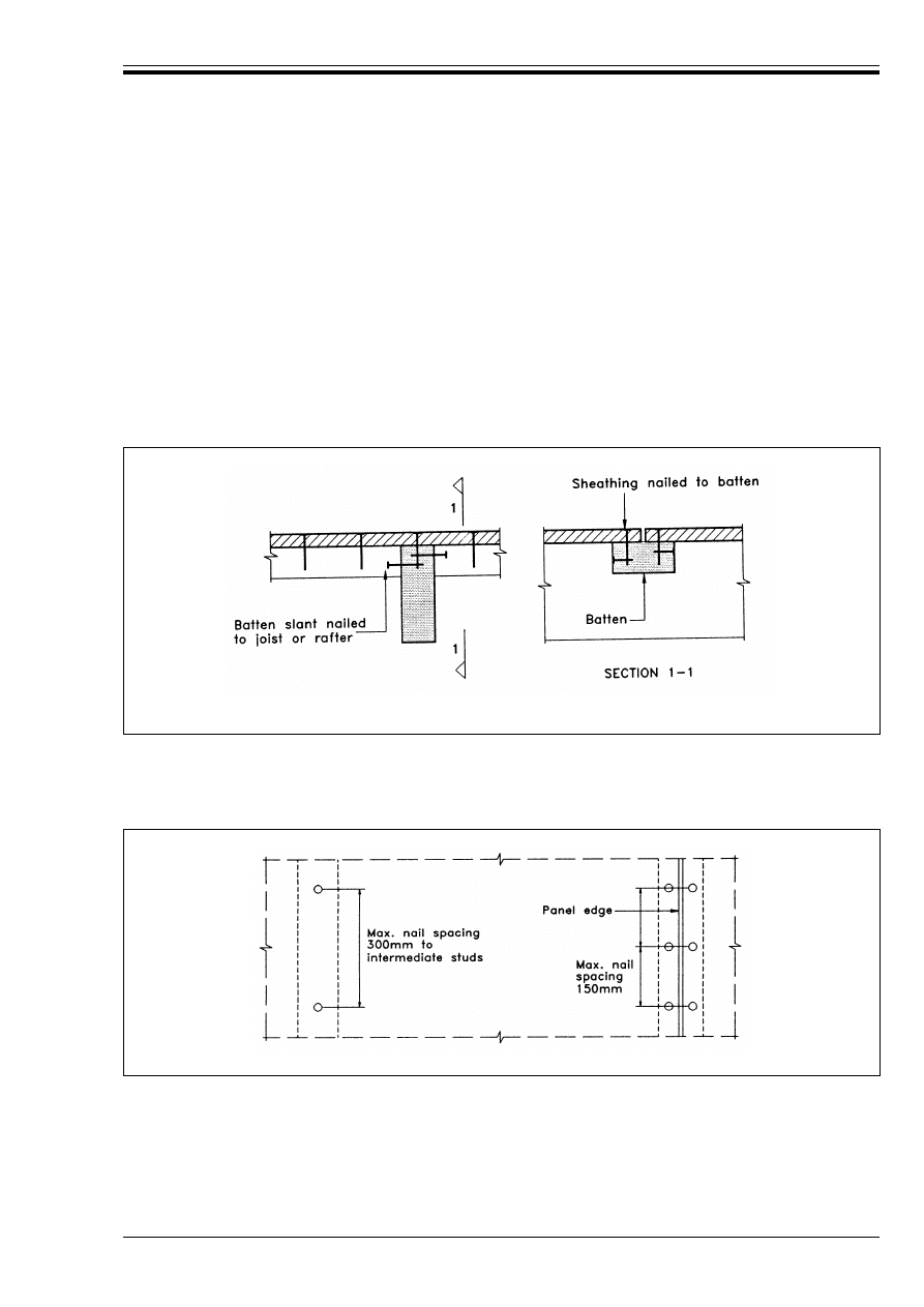
ENV 1995-1-1:1993
© BSI 02-2000
61
7.7.3 Controls after completion of the structure
(1) A control programme should specify the control measures (inspection maintenance) to be carried out in
service where long term compliance with the basic assumptions for the project is not adequately ensured.
(2) All the information required for the utilisation in service and the maintenance of a structure should be
made available to the person or authority who undertakes responsibility for the finished structure.
7.8 Special rules for diaphragm structures
7.8.1 Floor and roof diaphragms
(1) The simplified analysis given in 5.4.2 assumes that sheathing panels not supported by joists or rafters
are connected to each other, e.g. by means of battens as shown in Figure 7.8.1. Annular ringed-shank or
threaded nails, or screws, should be used, with a maximum spacing along the panel edges of 150 mm.
Elsewhere the maximum spacing should be 300 mm.
7.8.2 Wall diaphragms
(1) The maximum fastener spacing along the panel edges should be taken as 150 mm for nails and 200 mm
for screws. Elsewhere the maximum spacing should be taken as 300 mm.
7.9 Special rules for trusses with punched metal plate fasteners
7.9.1 Fabrication
(1) Trusses should be fabricated in accordance with prEN 1059.
Figure 7.8.1 — Examples of connection of panels not supported by a joist or a rafter.
Sheathing is nailed to battens which are slant nailed to the joists or rafters
Figure 7.8.2 — Panel fixings

ENV 1995-1-1:1993
62
© BSI 02-2000
7.9.2 Erection
(1) Trusses should be checked for straightness and vertical alignment prior to fixing the permanent
bracing.
(2) When trussed rafters are fabricated, the members should be free from distortion within the limits given
in prEN 1059. However, if members which have distorted during the period between fabrication and
erection can be straightened without damage to the timber or the joints and maintained straight, the
trussed rafter may be considered satisfactory for use.
(3) After erection, a maximum bow of 10 mm may be permitted in any trussed rafter member provided it is
adequately secured in the completed roof to prevent the bow from increasing.
(4) The maximum deviation from the true vertical alignment should not exceed 10 + 5 (H – 1) mm, with a
maximum value of 25 mm, where H is the overall rise of the trussed rafter in m.

ENV 1995-1-1:1993
© BSI 02-2000
63
Annex A (informative)
Determination of 5-percentile characteristic values from test results and
acceptance criteria for a sample
A.1 Scope
(1) This annex gives a method for calculating the 5-percentile characteristic value from the test results for
a population, and a method to estimate whether the 5-percentile value for a sample drawn from the
production is below a declared value.
(2) The method should not be used in cases covered by other European standards, or where other
assumptions than those set out below can be shown to be more appropriate.
A.2 Determination of the 5-percentile characteristic value
A.2.1
Requirements
(1) The 5-percentile value shall be estimated as the lower endpoint in the one-sided 84,1 % confidence
interval assuming a log-normal distribution. The coefficient of variation shall not be taken as less
than 0,10.
(2) The sample size n shall not be less than 30.
A.2.2
Method
(1) Draw a sample of n test pieces from the population, and test the pieces in accordance with the
appropriate standard for the property called x.
Determine the mean value m {x} and the coefficient of variation v {x}. Estimate the characteristic value x
k
as
where
The value of v {x} shall not be taken less than 0,10.
Values of k
1
are given in Table A.2.
NOTE The value determined by (A2.2a and A2.2b) is the highest value the producer may declare as the characteristic value. If the
product is subject to a quality control procedure involving testing and evaluation as described in A.3 it may be advisable to declare a
lower value to avoid an unreasonable rejection rate.
Table A.2 — Factor
k
1
A.3 Acceptance criteria for a sample
A.3.1
Requirements
(1) The probability of accepting a sample with a 5-percentile value less than 95 % of the declared
characteristic value f
k
should be less than 15.9 % assuming a log-normal distribution. It is assumed that
the value of the coefficient of variation is known, e.g., from a running production control. The coefficient of
variation shall not be taken as less than 0,10.
x
k
= k
1
m {x}
(A2.2a)
k
1
= exp [– (2,645 + 1/
) v {x} + 0,15]
(A2.2b)
Coefficient of
variation
Sample size n
v {x}
30
40
50
100
Z
0,10
0,12
0,14
0,16
0,18
0,20
0,22
0,24
0,26
0,28
0,30
0,876
0,827
0,781
0,738
0,697
0,659
0,622
0,588
0,556
0,525
0,496
0,878
0,830
0,785
0,742
0,701
0,663
0,627
0,593
0,561
0,530
0,501
0,879
0,832
0,787
0,744
0,704
0,665
0,629
0,595
0,563
0,532
0,504
0,883
0,836
0,791
0,749
0,709
0,671
0,635
0,601
0,569
0,539
0,510
0,892
0,846
0,802
0,761
0,722
0,685
0,649
0,616
0,584
0,554
0,525
n

ENV 1995-1-1:1993
64
© BSI 02-2000
A.3.2
Method
(1) Draw a sample of n test pieces from the batch, and test them in accordance with the appropriate
standard for the property called x.
Calculate the mean value m {x}.
The sample shall be accepted if
m {x} U k
2
f
k
where
k
2
= exp [(2,645 + 1/
) v {x} – 0,1875]
Values of k
2
are given in Table A.3.
Table A.3 — Factor
k
2
Annex B (informative)
Mechanically jointed beams
B.1 General
B.1.1
Cross sections
(1) The cross-sections shown in Figure B.1.1 are considered.
B.1.2
Structures and assumptions
(1) The design method is based on the theory of linear elasticity and the following assumptions:
— the beams are simply supported with a span 1. For continuous beams the formulae can be used with 1
equal to 0,8 times the relevant span: for cantilevered beams with 1 equal to twice the cantilever
— the individual parts (of wood, wood-based panels) are either full length or made with glued end joints
— the individual parts are connected to each other by mechanical fasteners with a slip modulus K
— the spacing s between the fasteners is constant or varies uniformly according to the shear force
between s
min
and s
max
with s
max
k 4 s
min
— the load is acting in the z-direction giving a moment M = M(x) varying sinusoidally or parabolically
and a shear force V = V(x).
B.1.3
Spacings
(1) Where a flange consists of two parts jointed to a web or where a web consists of two parts (as in a box
beam), the spacing S
i
is determined by the sum of the fasteners per unit length in the two jointing planes.
B.1.4
Deflections resulting from bending moments
(1) Deflections are calculated by using an effective bending stiffness (EI)
ef
determined in accordance
with B.2.
Coefficient of
variation
Sample size n
v {x}
3
5
10
20
50
100
Z
0,10
0,12
0,14
0,16
0,18
0,20
0,22
0,24
0,26
0,28
0,30
1,14
1,22
1,30
1,39
1,48
1,58
1,68
1,80
1,92
2,04
2,18
1,13
1,20
1,28
1,36
1,45
1,54
1,64
1,74
1,85
1,97
2,10
1,11
1,18
1,25
1,33
1,41
1,50
1,59
1,69
1,79
1,90
2,02
1,10
1,17
1,25
1,31
1,39
1,47
1,56
1,65
1,75
1,85
1,96
1,10
1,16
1,23
1,30
1,37
1,45
1,53
1,62
1,71
1,81
1,91
1,09
1,15
1,22
1,29
1,36
1,44
1,52
1,60
1,69
1,79
1,89
1,08
1,14
1,20
1,27
1,34
1,41
1,49
1,57
1,65
1,74
1,84
n
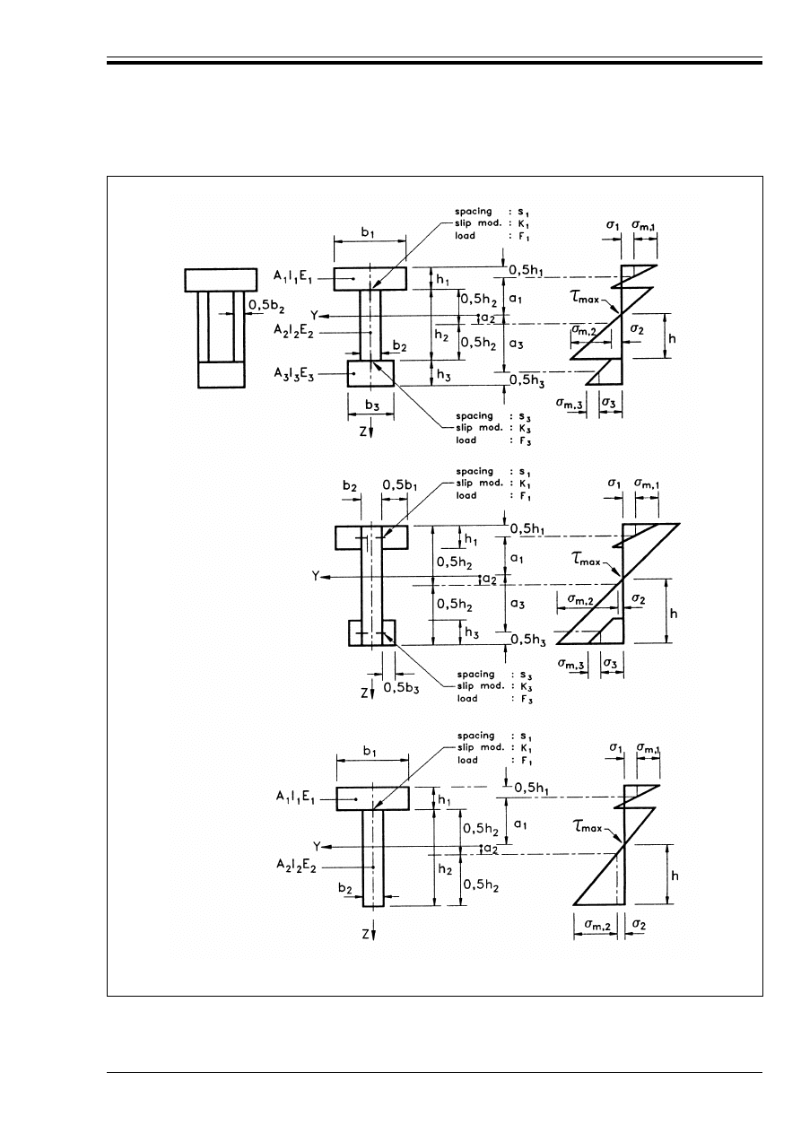
ENV 1995-1-1:1993
© BSI 02-2000
65
Figure B.1.1 — Cross-section (left) and distribution of bending stresses (right). All
measurements are positive except for a
2
which is taken as positive as shown
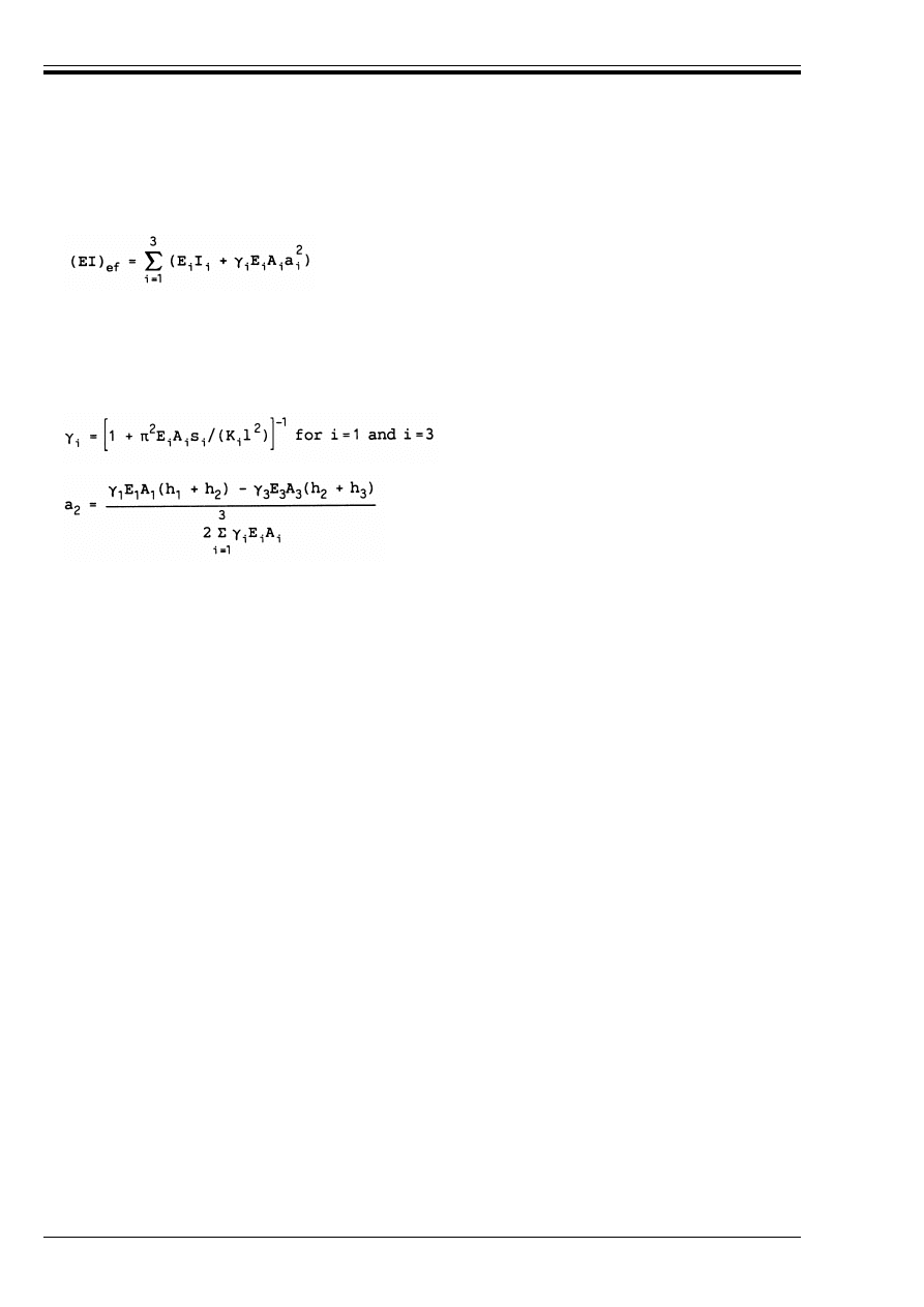
ENV 1995-1-1:1993
66
© BSI 02-2000
B.2 Effective bending stiffness
(1) The effective bending stiffness should be taken as
with mean values of E, and where:
B.3 Normal stresses
(1) The normal stresses should be taken as:
B.4 Maximum shear stress
(1) The maximum shear stresses occur where the normal stresses are zero. The maximum shear stress in
part 2 of the cross-section should be taken as
B.5 Fastener load
(1) The load on a fastener should be taken as
with i = 1 and 3, where s
i
= s
i
(x) is the spacing of the fasteners as defined in B.1.3, and V = V(x).
Annex C (informative)
Built up columns
C.1 General
C.1.1
Assumptions
(1) The following assumptions apply:
— the columns are simply supported with a length 1
— the individual parts are full length
— the load is an axial force F
c
acting in the geometric centre of gravity, (see however C.2.4).
C.1.2
Load carrying capacity
(1) For column deflection in the y-direction (see Figure C.3.1 and Figure C.4.1), the load-carrying capacity
is equal to the sum of the load-carrying capacities of the individual members.
(2) For column deflection in the z-direction (see Figure C.3.1 and Figure C.4.1) it is required that:
(B2a)
A
i
= b
i
h
i
(B2b)
I
i
= b
i
/12
(B2c)
*
2
= 1
(B2d)
(B2e)
(B2f)
For T-sections h
3
= 0
B
i
= *
i
E
i
a
i
M/(EI)
ef
(B3a)
B
m,i
= 0,5E
i
h
i
M/(EI)
ef
(B3b)
E
2,max
= (*
3
E
3
A
3
a
3
+ 0.5 E
2
b
2
h
2
) V/(b
2
(EI)
ef
)
(B4)
F
i
= *
i
E
i
A
i
a
i
s
i
V/(EI)
ef
(B5)
B
c,0,d
k k
c
f
c,0,d
(C1.2a)
h
3
i

ENV 1995-1-1:1993
© BSI 02-2000
67
where
C.2 Mechanically jointed columns
C.2.1
Assumptions
(1) Built-up columns with the cross-sections shown in Annex B are considered. It is, however, assumed that
where E
mean
should be used.
C.2.2
Effective slenderness ratio
(1) The effective slenderness ratio should be taken as
where
and (EI)
ef
is determined in accordance with Annex B.
C.2.3
Load on fasteners
(1) The load on a fastener should be determined in accordance with Annex B, (B.5), where:
C.2.4
Combined loads
(1) In cases where small moments resulting from e.g. self weight are acting apart from axial load, 5.2.1(4)
applies.
C.3 Spaced columns with packs or gussets
C.3.1
Assumptions
(1) Columns as shown in Figure C.3.1 are considered, i.e. columns with shafts spaced with packs or gussets.
The joints may be either nailed or glued or bolted with suitable connectors.
B
c,0,d
=
F
c,d
/A
tot
(C1.2b)
A
tot
is the total cross-sectional area
k
c
is determined in accordance with clause 5.2.1 but with an effective slenderness
ratio 2
ef
determined in accordance with sections C.2 – C.4.
E
1
= E
2
= E
3
= E
(C2.1)
(C2.2a)
I
ef
= (EI)
ef
/E
(C2.2b)
V
d
=
F
c,d
/(120 k
c
)
for
2
ef
k 30
(C2.3a)
F
c,d
2
e,f
/(3600 k
c
)
for 30 < 2
ef
k 60
(C2.3b)
F
c,d
/(60 k
c
)
for 60 < 2
ef
(C2.3c)
2
ef
l A
tot
/
I
ef
=
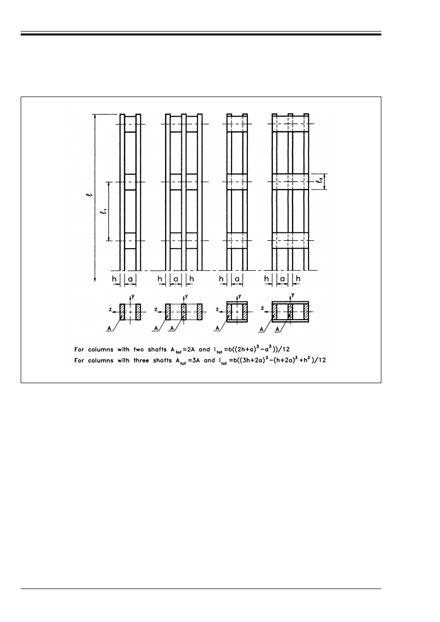
ENV 1995-1-1:1993
68
© BSI 02-2000
(2) The following assumptions apply:
— the cross-section is composed of 2, 3 or 4 identical shafts
— the cross-sections are doubly symmetrical
— the number of free bays is at least 3, i.e. the shafts are at least connected at the ends and at the third
points
— the free distance a between the shafts is not greater than 3 times the shaft thickness h for columns
with packs and not greater than 6 times the shaft thickness for columns with gussets
— the joints, packs and gussets are designed in accordance with C.3.3
— the pack length l
2
satisfies the condition: l
2
/a U 1,5
— there are at least 4 nails or 2 bolts with connectors in each shear plane. For nailed joints there are at
least 4 nails in a row at each end in the longitudinal direction of the column
— the length of the gussets satisfies the condition: l
2
/a U 2
— the columns are subjected to concentric axial loads.
C.3.2
Axial load-carrying capacity
(1) For column deflection in the y-direction (see Figure C.3.1) the load-carrying capacity is equal to the sum
of the load-carrying capacities of the individual members.
Figure C.3.1 — Spaced columns
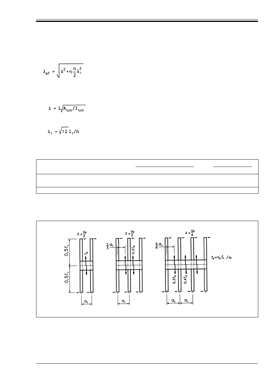
ENV 1995-1-1:1993
© BSI 02-2000
69
(2) For column deflection in the z-direction C.1.2 applies with
where
2 is the slenderness ratio for a solid column with the same length, the same area (A
tot
) and the same
second moment of area (I
tot
), i.e.,
2
1
is the slenderness ratio for the shafts. A minimum value of 2
1
= 30 should be used in (C3.2b).
n is the number of shafts
) is a factor given in Table C.3.2.
Table C.3.2 — The factor )
C.3.3
Load on fasteners gussets and packs
(1) The load on the fasteners gussets and packs should taken as shown in Figure C.3.3 with V
d
according
to section C.2.3.
C.4 Lattice columns with glued or nailed joints
C.4.1
Structures
(1) Lattice columns with N- or V-lattice and with glued or nailed joints are considered, see Figure C.4.1.
(C3.2a)
(C3.2b)
(C3.2c)
packs
gussets
glued/nailed/bolted
a
glued/nailed
permanent/long-term loading
medium/short-term loading
1
1
4
3
3,5
2,5
3
2
6
4,5
a
with connectors
Figure C.3.3 — Shear force distribution and loads on gussets and packs
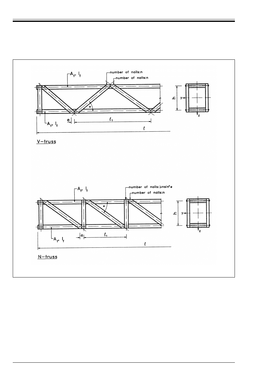
ENV 1995-1-1:1993
70
© BSI 02-2000
(2) The following assumptions apply:
— the structure is symmetrical about the y- and z-axes of the cross-section. The lattice of the two sides
may be staggered by a length of =
1
/2, where =
1
is the node distance
— there are at least 3 bays
— in nailed structures there are at least 4 nails per shear plane in each diagonal at each nodal point
— each end is braced
— the slenderness ratio of the individual flange corresponding to the node length =
1
is not greater
than 60
— no local rupture occurs in the flanges corresponding to the column length =
1
— the number of nails in the verticals (of an N-truss) is greater than n sin
2
F, where n is the number of
nails in the diagonals and F is the inclination of the diagonals.
Figure C.4.1 — Lattice columns. The area of one flange is A
f
and the second moment of
area about its own axis of gravity is I
f
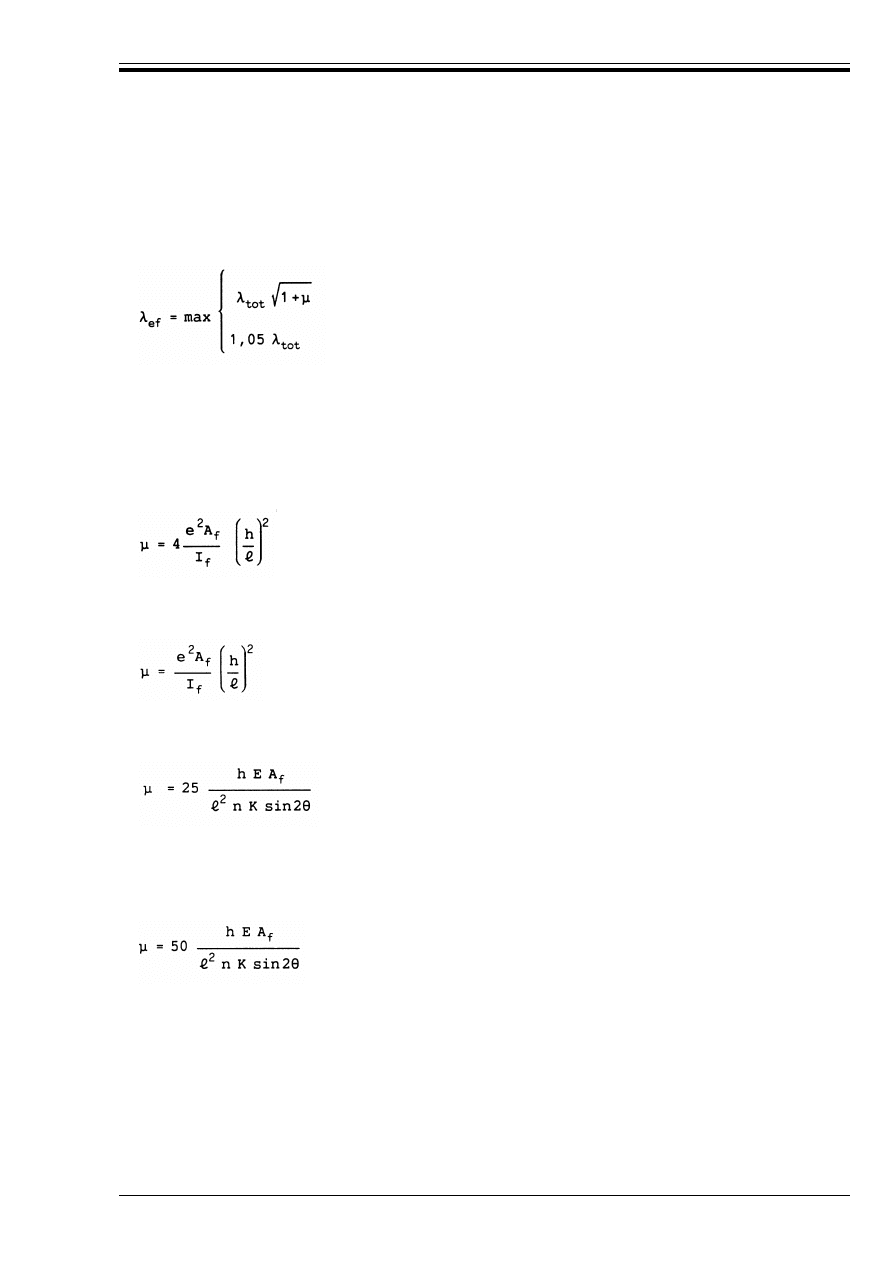
ENV 1995-1-1:1993
© BSI 02-2000
71
C.4.2
Load carrying capacity
(1) The load-carrying capacity corresponding to the deflection of the column in the y-direction is equal to
the sum of the load-carrying capacities of the flanges for deflection.
(2) For column deflection in the z-direction C.1.2 applies with:
where 2
tot
is the slenderness ratio for a solid column with the same length, the same area and the same
second moment of area, i.e.
and 4 takes the values given below.
(3) For glued V-trusses
where e is defined in Figure C.4.1.
(4) 0 For glued N-trusses
where e is defined in Figure C.4.1.
(5) For nailed V-trusses
where n is the number of nails in a diagonal and K is the slip modulus of one nail. If a diagonal consists of
two or more pieces, n is the sum of the nails (and not the number of nails per shear plane). E
mean
should
be used.
(6) For nailed N-trusses
where n is the number of nails in a diagonal and K is the slip modulus of one nail. If a diagonal consists of
two or more pieces, n is the sum of the nails (and not the number of nails per shear plane). E
mean
should
be used.
C.4.3
Shear forces
C.2.3
applies.
(C4.2a)
(C4.2b)
2
tot
ë
(C4.2c)
(C4.2d)
(C4.2e)
(C4.2f)
(C4.2g)
2
=
h
------

ENV 1995-1-1:1993
72
© BSI 02-2000
Annex D (normative)
The design of trusses with punched metal plate fasteners
D.1 General
(1) The requirements of 5.4.1.1 apply.
(2) The method given in this annex may be applied to trusses with other fasteners of a similar form, such
as nailed metal plates or plywood gussets.
D.2 Joints
(1) Splice joints may be modelled as rotationally stiff if the actual rotation under load would have no
significant effect upon member forces. This requirement is fulfilled by:
— splice joints with a resistance which is at least equal to 1,5 times the combination of applied force and
moment
— splice joints with a resistance which corresponds at least to the combination of applied force and
moment, provided that
— the joint is not subject to bending stresses which are greater than 0,3 times the member bending
strength, and
— the assembly would be stable if all such joints acted as pins.
(2) The influence of slip in the joints should be modelled either as slip moduli, or as prescribed slip values
which relate to the actual stress level in the joint.
(3) Values of the instantaneous slip modulus K
ser
, or the prescribed slip u
ser
for the serviceability limit
state should be determined by tests according to the method for determining k (= K
ser
) given in EN 26891.
(4) The instantaneous slip modulus for the ultimate limit state, K
u
, is given by
(5) The final slip modulus K
u,fin
, is given by
(6) The prescribed slip for the ultimate limit state, u
u
, is given by
(7) The final prescribed slip is given by
D.3 General analysis
(1) The requirements of 5.4.1.2 apply.
(2) For fully triangulated trusses where a small concentrated force (e.g. a man load) has a component
perpendicular to the member of < 1,5 kN, and where B
c,d
< 0,4 f
c,d
and B
t,d
< 0, 4 f
t,d
the requirements
of 5.1.9 and 5.1.10 should be replaced by
D.4 Simplified analysis
(1) The requirements of 5.4.1.3 apply.
(2) The supports may be modelled as pinned if not less than half the width of the bearing is vertically below
the eaves joint fastener, and the distance a
2
in Figure D.4 is not greater than a
1
/3 or 100 mm, whichever
is the greater.
K
u
= 2K
ser
/3
(D2a)
K
u,fin
= K
u
/(1 + k
def
)
(D2b)
u
u
= 2,0 u
ser
(D2C)
u
u,fin
= u
u
(1 + k
def
)
(D.2d)
B
m,d
k 0,75f
m,d
(D3)
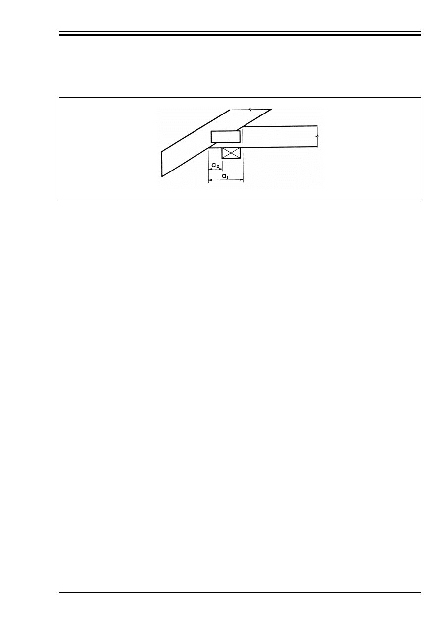
ENV 1995-1-1:1993
© BSI 02-2000
73
(3) For trusses which are loaded predominantly at the nodes, the sum of the combined bending and axial
compression stress ratios given in equations 5.1.10a and b should be limited to 0,9.
D.5 Strength verification of members
(1) The requirements of Chapter 5 apply.
D.6 Punched metal plate fasteners
D.6.1
General
(1) The following rules apply only to plates with two orthogonal directions.
D.6.2
Plate geometry
(1) The geometry of the plate is given in Figure D.6.2. The symbols are defined as follows:
Figure D.4 — Rules for a pinned support
x-direction
main direction of plate
y-direction
perpendicular to the main direction
!
angle between the x-direction and the force F
"
angle between the grain direction and the force F
*
angle between the x-direction and the joint line
A
ef
the effective area, that is, the area of the total contact surface between the plate and the
timber, reduced by those parts of the surface which are outside some specified dimension
from the edges and ends
=
length of the plate along the joint line
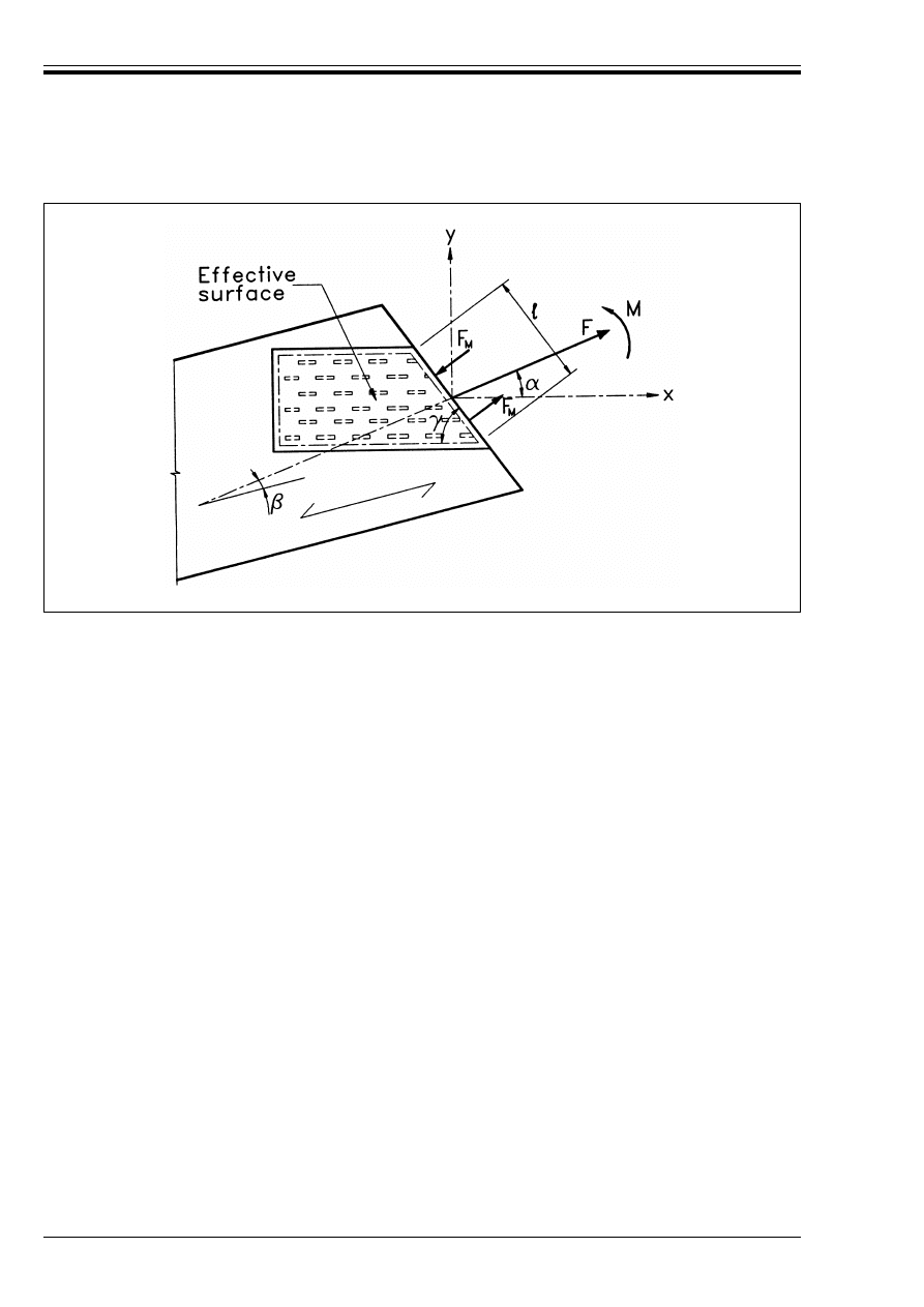
ENV 1995-1-1:1993
74
© BSI 02-2000
D.6.3
Plate strength capacities
(1) The plate shall have approved characteristic values determined from the results of tests carried out in
accordance with the methods described in prEN 1075 for the following properties:
(2) In order to calculate the design tension, compression and shear capacities of the plate the value of k
mod
shall be taken as 1,0 and *
m
as 1,1.
D.6.4
Anchorage strengths
The design anchorage strength f
a,!,",d
should either be derived from tests or calculated from:
when " k 45°, or
when 45° < " k 90°
The design anchorage strength in the grain direction is given by:
Figure D.6.2 — Geometry of nail plate connection loaded by a force F and moment M
f
a,0,0
the anchorage capacity per unit area for ! = 0° and " = 0°
f
a,90,90
the anchorage capacity per unit area for ! = 90° and " = 90°
f
t,0
the tension capacity per unit width of the plate in the x-direction (! = 0°)
f
c,0
the compression capacity per unit width of the plate in the x-direction (! = 0°)
f
v,0
the shear capacity per unit width of the plate in the x-direction (! = 0°)
f
t,90
the tension capacity per unit width of the plate in the y-direction (! = 90°)
f
c,90
the compression capacity per unit width of the plate in the y-direction (! = 90°)
f
v,90
the shear capacity per unit width of the plate in the y-direction (! = 90°)
k
1
,k
2
,!
o
constants
f
a,!,",d
= max
f
a,!,0,d
– (f
a,!,0,d
– f
!,90,90,d
) "/45°
(D6.4a)
f
a,0,0,d
– (f
a,0,0,d
– f
a,90,90,d
) sin(max (!,")),
(D6.4b)
f
a,!,",d
= f
a,0,0,d
– (f
a,0,0,d
– f
a,90,90,d
) sin(max (!,")),
(D6.4c)
f
a,!,0,d
=
f
a,0,0,d
+ k
1
!
when ! k !
0
(D6.4d)
f
a,0,0,d
+ k
1
!
0
+ k
2
(! – !
0
)
when !
0
< ! k 90°
(D6.4e)
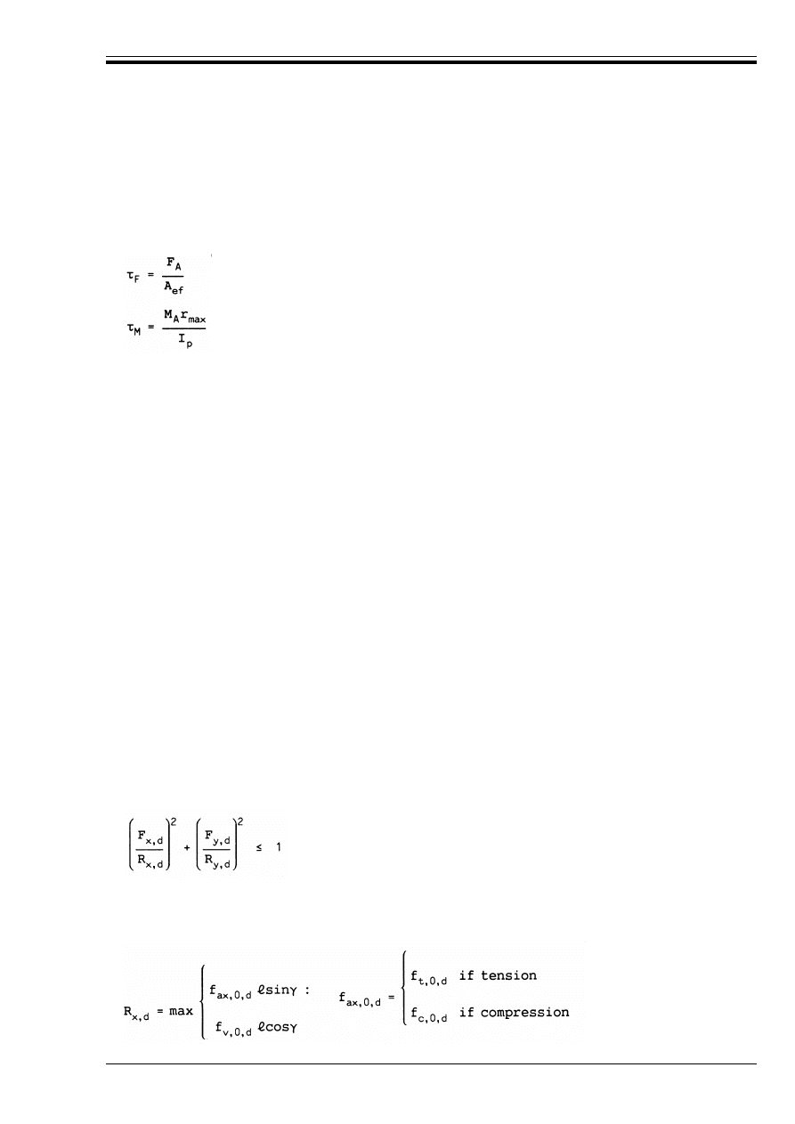
ENV 1995-1-1:1993
© BSI 02-2000
75
The constants k
1
, k
2
and !
0
should be determined by tests in accordance with prEN 1075 for the actual type
of nail plate.
D.6.5
Joint strength verification
D.6.5.1 Plate anchorage capacity
(1) The anchorage stresses E
F
and E
M
are calculated from:
where the symbols are defined as follows:
(2) Contact pressure between timber members may be taken into account to reduce the value of F
A
in
compression provided that the gap between the members has an average value which is not greater
than 1 mm, and a maximum value of 2 mm. In such cases the joint should be designed for a minimum
compression force of F
A
/2.
(3) The following conditions should be satisfied:
D.6.5.2 Plate capacity
(1) For a connection with one straight joint the forces in the two main directions are determined from the
following formulae. A positive value signifies a tension force, a negative value a compression force.
where the symbols are defined as follows:—
(2) The following condition should be satisfied:
where F
x, d
and F
y, d
are the design values of the forces in the x- and y- directions, and R
x,d
and R
y,d
are the
design values of the plate capacity in the x- and y- directions. The latter are determined as the maximum
of the capacities at sections parallel with or perpendicular to the main axes.
(D6.5.1a)
(D6.5.1b)
F
A
force acting on the plate at the centroid of the effective area
M
A
moment acting on the plate
I
p
polar moment of inertia of the effective area
r
max
the distance from the centroid to the furthest point of the effective area.
E
F,d
k f
a,!,",d
(D6.5.1c)
E
M,d
k 2f
a,90,90,d
(D6.5.1d)
E
F,d
+ E
M,d
k 1,5f
a,0,0,d
(D6.5.1e)
F
x
= F cos! ± 2F
M
sin*
(D6.5.2a)
F
y
= F sin! ± 2F
M
cos*
(D6.5.2b)
F
is the force in the joint
F
M
is the force from the moment M in the joint (F
M
= 2M/=)
(D.6.5.2c)
(D.6.5.2d)

ENV 1995-1-1:1993
76
© BSI 02-2000
(3) If the plate covers several joints, then the forces in each straight part of the joint line should be
determined so that equilibrium is fulfilled and the condition in expressions (D.6.5.2c) is satisfied in each
straight part.
(4) All critical sections should be considered.
D.6.5.3 Minimum anchorage requirements
(1) All joints should be capable of transferring a force F
r,d
acting in any direction. F
r,d
shall be assumed to
be a short-term force, acting on timber in service class 2 with the value
where L is the length of the truss in metres.
(2) The minimum overlap of the punched metal plate and the timber should be at least equal to 40 mm or
h/3, where h is the height of the timber member.
(3) Nail plates in chord splices should cover at least
? of the timber width.
(D.6.5.2e)
F
r,d
= 1,0 + 0,1L kN
(D.6.5.3)

DD ENV 1995-1-1:1994
© BSI 02-2000
National annex NA (informative)
Committees responsible
The preparation of the National Application Document for use in the UK with ENV 1995-1-1:1993 was
entrusted by Technical Committee B/525, Building and civil engineering structures, to Subcommittee
B/525/5, Structural use of timber, upon which the following bodies were represented.
British Woodworking Federation
Department of the Environment (Building Research Establishment)
Department of the Environment (Construction Directorate)
Health and Safety Executive
Institution of Civil Engineers
Institution of Structural Engineers
National House-building Council
Timber Research and Development Association
Timber Trade Federation
DD ENV
1995-1-1:1994
BSI
389 Chiswick High Road
London
W4 4AL
BSI — British Standards Institution
BSI is the independent national body responsible for preparing
British Standards. It presents the UK view on standards in Europe and at the
international level. It is incorporated by Royal Charter.
Revisions
British Standards are updated by amendment or revision. Users of
British Standards should make sure that they possess the latest amendments or
editions.
It is the constant aim of BSI to improve the quality of our products and services.
We would be grateful if anyone finding an inaccuracy or ambiguity while using
this British Standard would inform the Secretary of the technical committee
responsible, the identity of which can be found on the inside front cover.
Tel: 020 8996 9000. Fax: 020 8996 7400.
BSI offers members an individual updating service called PLUS which ensures
that subscribers automatically receive the latest editions of standards.
Buying standards
Orders for all BSI, international and foreign standards publications should be
addressed to Customer Services. Tel: 020 8996 9001. Fax: 020 8996 7001.
In response to orders for international standards, it is BSI policy to supply the
BSI implementation of those that have been published as British Standards,
unless otherwise requested.
Information on standards
BSI provides a wide range of information on national, European and
international standards through its Library and its Technical Help to Exporters
Service. Various BSI electronic information services are also available which give
details on all its products and services. Contact the Information Centre.
Tel: 020 8996 7111. Fax: 020 8996 7048.
Subscribing members of BSI are kept up to date with standards developments
and receive substantial discounts on the purchase price of standards. For details
of these and other benefits contact Membership Administration.
Tel: 020 8996 7002. Fax: 020 8996 7001.
Copyright
Copyright subsists in all BSI publications. BSI also holds the copyright, in the
UK, of the publications of the international standardization bodies. Except as
permitted under the Copyright, Designs and Patents Act 1988 no extract may be
reproduced, stored in a retrieval system or transmitted in any form or by any
means – electronic, photocopying, recording or otherwise – without prior written
permission from BSI.
This does not preclude the free use, in the course of implementing the standard,
of necessary details such as symbols, and size, type or grade designations. If these
details are to be used for any other purpose than implementation then the prior
written permission of BSI must be obtained.
If permission is granted, the terms may include royalty payments or a licensing
agreement. Details and advice can be obtained from the Copyright Manager.
Tel: 020 8996 7070.
Wyszukiwarka
Podobne podstrony:
Eurocode 3 Part 1,1 DDENV 1993 1 1 1992
Eurocode 1 Part 4 DDENV 1991 4 1995
Eurocode 3 Part 1,3 DDENV 1993 1 3 1996
Eurocode 3 Part 1,1 DDENV 1993 1 1 1992
Eurocode 3 Part 1,1 DDENV 1993 1 1 1992
Eurocode 3 Part 1 11 Pren 1993 1 11 (Eng)
Eurocode 4 Part 2 DDENV 1994 2 1997
Eurocode 3 Part 1,10 prEN 1993 1 10 2003
Eurocode 7 Part 2 DDENV 1997 2 1999
Eurocode 9 Part 2 DDENV 1999 2 1998
Eurocode 6 Part 3 DDENV 1996 3 1999
Eurocode 7 Part 1 DDENV 1997 1 1994
Eurocode 9 Part 1,1 DDENV 1999 1 1 1998
Eurocode 2 Part 2 DDENV 1992 2 1996
Eurocode 6 Part 1,3 DDENV 1996 1 3 2001
Eurocode 2 Part 1,6 DDENV 1992 1 6 1994
Eurocode 9 Part 1,2 DDENV 1999 1 2 1998
więcej podobnych podstron