DRAFT FOR DEVELOPMENT
DD ENV
1993-1-1:1992
Eurocode 3: Design of
steel structures —
Part 1.1: General rules and rules for
buildings —
(together with United Kingdom
National Application Document)
UDC 624.92.014.2:624.07

DD ENV 1993-1-1:1992
This Draft for Development,
having been prepared under
the direction of the Technical
Sector Board for Building
and Civil Engineering (B/-),
was published under the
authority of the Standards
Board and comes into effect on
15 November 1992
© BSI 04-2000
The following BSI reference
relates to the work on this
Draft for Development:
Committee reference B/525/31
ISBN 0 580 21226 2
Cooperating organizations
The European Committee for Standardization (CEN), under whose supervision
this European Standard was prepared, comprises the national standards
organizations of the following countries:
Austria
Oesterreichisches Normungsinstitut
Belgium
Institut belge de normalisation
Denmark
Dansk Standardiseringsraad
Finland
Suomen Standardisoimisliito, r.y.
France
Association française de normalisation
Germany
Deutsches Institut für Normung e.V.
Greece
Hellenic Organization for Standardization
Iceland
Technological Institute of Iceland
Ireland
National Standards Authority of Ireland
Italy
Ente Nazionale Italiano di Unificazione
Luxembourg
Inspection du Travail et des Mines
Netherlands
Nederlands Normalisatie-instituut
Norway
Norges Standardiseringsforbund
Portugal
Instituto Portuguès da Qualidade
Spain
Asociación Española de Normalización y Certificación
Sweden
Standardiseringskommissionen i Sverige
Switzerland
Association suisse de normalisation
United Kingdom
British Standards Institution
Amendments issued since publication
Amd. No.
Date
Comments

DD ENV 1993-1-1:1992
© BSI 04-2000
i
Contents
Page
Cooperating organizations
Inside front cover
National foreword
ii
Text of National Application Document
v
Foreword
2
Text of ENV 1993-1-1
13
National annex NA (informative) Committees responsible
Inside back cover

DD ENV 1993-1-1:1992
ii
© BSI 04-2000
National foreword
This publication comprises the English language version of ENV 1993-1-1:1992
Eurocode 3: Design of Steel Structures — Part 1.1: General rules and rules for
buildings, as published by the European Committee for Standardization (CEN),
plus the National Application Document (NAD) to be used with the ENV on the
design of buildings to be constructed in the United Kingdom (UK).
ENV 1993-1-1:1992 results from a programme of work sponsored by the
European Commission to make available a common set of rules for the design of
building and civil engineering works.
An ENV is made available for provisional application, but does not have the
status of a European Standard. The aim is to use the experience gained to modify
the ENV so that it can be adopted as a European Standard.
The values for certain parameters in the ENV Eurocodes may be set by CEN
members so as to meet the requirements of national regulations. These
parameters are designated by in the ENV.
During the ENV period reference should be made to the supporting documents
listed in the National Application Document (NAD).
The purpose of the NAD is to provide essential information, particularly in
relation to safety, to enable the ENV to be used for buildings constructed in the
UK. The NAD takes precedence over corresponding provisions in the ENV.
The Building Regulations 1991, Approved Document A 1992,
(published December 1991) identifies ENV 1993-1-1:1992 as appropriate
guidance, when used in conjunction with the NAD, for the design of steel
buildings.
Compliance with ENV 1993-1-1:1992 and the NAD does not in itself confer
immunity from legal obligations.
Users of this document are invited to comment on its technical content, ease of
use and any ambiguities or anomalies. These comments will be taken into account
when preparing the UK national response to CEN on the question of whether the
ENV can be converted to an EN.
Comments should be sent in writing to BSI, 2 Park Street, London W1A 2BS
quoting the document reference, the relevant clause and, where possible, a
proposed revision, within 2 years of the issue of this document.
Summary of pages
This document comprises a front cover, an inside front cover, pages i to xxii,
the ENV title page, pages 2 to 270, an inside back cover and a back cover.
This standard has been updated (see copyright date) and may have had
amendments incorporated. This will be indicated in the amendment table on the
inside front cover.

DD ENV 1993-1-1:1992
© BSI 04-2000
iii
National Application
Document
for use in the UK with
ENV 1993-1-1:1991

DD ENV 1993-1-1:1992
iv
© BSI 04-2000
Contents of National Application
Document
Page
Introduction
v
1
Scope
v
2
References
v
3
Partial safety factors, combination factors and other values
v
4
Loading codes
vii
5
Reference standards
viii
6
Additional recommendations
xi
Annex A (normative) General recommendations for structural integrity
xvi
Annex B (normative) Application rules for columns in simple framing
xvii
Table 1 — Partial safety factors (¾ factors)
v
Table 2 — Partial safety factors for fatigue strength
vi
Table 3 — Combination factors (Ò factors)
vii
Table 4 — Combination factors for accidental loads
vii
Table 5 — Reference standard 1. Weldable structural steel
viii
Table 6 — Reference standard 2. Dimensions of sections and plates
viii
Table 7 — Reference standard 2. Dimensions of sections and
plates: tolerances
ix
Table 8 — Reference standard 3. Bolts, nuts and
washers: non-pre-loaded bolts
x
Table 9 — Reference standard 3. Bolts, nuts and
washers: pre-loaded bolts
x
Table 10 — Reference standard 4. Welding consumables
x
Table 11 — Reference standard 5. Rivets
xi
Table 12 — Reference standards 6 to 9. Execution standards
xi
Table 13 — Reference standard 10. Corrosion protection
xi
Table 14 — Directly referenced supporting standards
xi
Table 15 — Maximum thickness for statically loaded structural elements
xiii
List of references
xix

ENV 1993-1-1:1992
© BSI 04-2000
v
Introduction
This National Application Document (NAD) has been prepared under the direction of the Technical Sector
Board for Building and Civil Engineering. It has been developed from:
a) a textual examination of ENV 1993-1-1:1992;
b) a parametric calibration against BS 5950, supporting standards and test data;
c) trial calculations.
1 Scope
This NAD provides information to enable ENV 1993-1-1:1992 (EC3-1.1) to be used for the design of
buildings to be constructed in the UK.
2 References
2.1 Normative references
This National Application Document incorporates, by reference, provisions from specific editions of other
publications. These normative references are cited at the appropriate points in the text and the
publications are listed on page xix. Subsequent amendments to, or revisions of, any of these publications
apply to this National Application Document only when incorporated in it by updating or revision.
2.2 Informative references
This National Application Document refers to other publications that provide information or guidance.
Editions of these publications current at the time of issue of this standard are listed on page xix, but
reference should be made to the latest editions.
3 Partial safety factors, combination factors and other values
a) The values for partial safety factors (¾) should be those given in Table 1 and Table 2 of this NAD.
b) The values for combination factors (Ò) should be those given in Table 3 and Table 4 of this NAD.
c) The value of the reduction factor Ò
vec
should be taken as 0.7.
Table 1 — Partial safety factors (¾ factors)
Reference
in EC3-1.1
Definition
Symbol
Condition
Value
Boxed
EC3
UK
2.3.2.2(1) Partial safety factors for
accidental actions
¾
A
Accidental
1.00
1.05
2.3.2.2(3) Partial safety factors for
permanent actions in
accidental design situation
¾
GA
¾
GA
Favourable
Unfavourable
1.00
1.00
0.90
1.05
2.3.3.1(1) Partial safety factors for
permanent actions
¾
G, inf
¾
G, sup
Favourable
Unfavourable
1.00
1.35
1.00
1.35
2.3.3.1(1) Partial safety factors for
variable action
¾
Q, inf
¾
Q, sup
¾
Q, sup
Favourable
Unfavourable
2 or more combined
0.00
1.50
1.50
0.00
1.50
1.50
2.3.3.1(3) Partial safety factors for
permanent action
¾
G, inf
¾
G, sup
¾
G, inf
Favourable part
Unfavourable part
Favourable and
unfavourable parts
1.10
1.35
1.00
1.10
1.35
1.00
DD ENV 1993-1-1:1992
vi
© BSI 04-2000
Table 1 — Partial safety factors (¾ factors)
Table 2 — Partial safety factors for fatigue strength
Reference
in EC3-1.1
Definition
Symbol
Condition
Value
Boxed
EC3
UK
5.1.1
Partial safety factors for steel ¾
M0
¾
M1
¾
M1
¾
M2
Resistance of Class 1, 2 or 3
cross-sections
Resistance of Class 4
cross-sections
Resistance of a member to
buckling
Resistance of net section at
bolt holes
1.10
1.10
1.10
1.25
1.05
1.05
1.05
1.20
6.1.1
Partial safety factors for
connections
¾
Mb
¾
Mr
¾
Mp
¾
Mw
Bolts
Rivets
Pins
Welds
1.25
1.25
1.25
1.25
1.35
1.35
1.35
1.35
6.5.8.1
Partial safety factors for slip
resistance
¾
Ms.ult
¾
Ms.ser
¾
Ms.ult
Ultimate limit state
Serviceability limit state
Ultimate limit state with
oversize or slotted holes
1.25
1.10
1.40
1.20
1.35
1.35
9.3.2
Partial safety factors for
fatigue loading
¾
Ff
Fatigue loading
1.00
1.00
9.3.4
Partial safety factors for
fatigue strength
¾
Mf
Fatigue strength
—
See
Table 2
C.2.5
¾ factors for brittle fracture
¾
C1
C1
1.00
1.00
C.2.5
¾ factor for brittle fracture
¾
C2
C2
Fe 430 or
Fe E 275
1.50
1.20
Fe 510 or
Fe E 355
1.50
1.10
All other grades
1.50
1.50
K.1
Partial safety factor for joint
resistance
¾
Mj
Hollow section lattice girder
connections
1.10
1.05
Inspection and access
“Fail-safe”
components
Non-“fail-safe”
components
Periodic inspection
a
and maintenance
Accessible joint detail
1.0
1.0
Periodic inspection
a
and maintenance
Poor accessibility
1.0
1.0
a
See 9.3.1(2) of EC3-1.1 concerning inspection.
DD ENV 1993-1-1:1992
© BSI 04-2000
vii
Table 3 — Combination factors (Ò factors)
Table 4 — Combination factors for accidental loads
4 Loading codes
The loading codes to be used are:
BS 648:1964, Schedule of weights of building materials.
BS 6399, Loading for buildings.
BS 6399-1:1984, Code of practice for dead and imposed loads.
BS 6399-3:1988, Code of practice for imposed roof loads.
CP 3, Code of basic data for the design of buildings.
CP 3:Chapter V, Loading.
CP 3:Chapter V-2:1972, Wind loads.
In using these documents with EC 3-1.1 the following modifications should be noted.
a) The imposed floor loads of a building should be treated as one variable action to which the reduction
factors given in BS 6399-1:1984 are applicable.
b) The wind loading should be taken as 90 % of the value obtained from CP 3:Chapter V-2:1972.
Variable action
a
Ò
0
Ò
1
Ò
2
Imposed
floor loads
Dwellings
0.5
0.4
0.2
Office and stores
0.7
0.6
0.3
Parking
0.7
0.7
0.6
Wind loads
0.7
0.2
0
Imposed roof loads
b
0.7
0.2
0
Crane
loads
c
Vertical
Horizontal
0.7
0.6
0.3
0.9 (vertical +
horizontal)
a
For the purpose of EC3-1.1 these four categories of variable actions should be treated as
separate and independent variable actions.
b
Local drifting of snow on roofs should be treated as an accidental action [see 6.1.1 c)].
c
The most onerous of the three specified alternatives should be treated as a single
variable action.
Variable action
Ò
1
or
Ò
2
for use
in A.3 and A.4
Imposed
floor loads
Dwellings
0.35
a
Offices
0.35
a
Stores
1.0
Parking
0.35
a
Wind loads
b
0.35
Imposed roof loads
0.35
Crane loads
c
Vertical
1.00
Horizontal
0.00
a
Where the variable action is of a persistent or quasi-permanent nature,
the Ò factor should be taken as 1.0.
b
The full value obtained from CP 3:Chapter V-2:1972 should be multiplied
by 0.35.
c
The values given in this table assume that the crane is stationary. The
vertical load to which the combination factor is applied is the static load
value.

DD ENV 1993-1-1:1992
viii
© BSI 04-2000
5 Reference standards
The supporting standards to be used, including materials specifications and standards for construction, are
listed in Table 5 to Table 14.
Table 5 — Reference standard 1. Weldable structural steel
Table 6 — Reference standard 2. Dimensions of sections and plates
Topic
EC3-1.1 calls up
UK supporting standard
Hot rolled
EN 10025
BS EN 10025 and BS 4360
prEN 10113
BS EN 10113 and BS 4360
prEN 10210-1
BS 4360
Cold formed
prEN 10219-1
BS 6363
Topic
EC3-1.1 calls up
UK supporting
standard
Hot rolled sections excluding structural
hollow sections
EN 10025
BS EN 10025
EN . . . . .
[B.2.2.1(2)]
BS 4
EN . . . . .
[B.2.2.1(3)]
BS 4
EN . . . . .
[B.2.2.1(4)]
BS 4848-5
EN . . . . .
[B.2.2.1(5)]
BS 4
EN . . . . .
[B.2.2.1(6)]
BS 4
EN . . . . .
[B.2.2.1(7)]
BS 4848-4
ISO 657-1 and
ISO 657-2
ISO 657-1 and
ISO 657-2
EN . . . . .
[B.2.2.1(9)]
BS 4360
EN . . . . .
[B.2.2.1(10)]
BS 4360
EN . . . . .
[B.2.2.1(11)]
BS 4360
Hot rolled structural hollow sections
prEN 10210-2
BS 4848-2
ISO 657-14
ISO 657-14
Cold finished structural hollow sections
prEN 10219-2-2
BS 6363
ISO 4019
ISO 4019

DD ENV 1993-1-1:1992
© BSI 04-2000
ix
Table 7 — Reference standard 2. Dimensions of sections and
plates: tolerances
Topic
EC3-1.1 calls up
UK supporting
standard
Hot rolled sections excluding structural
hollow sections
prEN 10034
BS 4
prEN 10056
BS 4848-4
EN . . . . .
[B.2.3.1(3)]
BS 4
EN . . . . .
[B.2.3.1(4)]
BS 4
EN . . . . .
[B.2.3.1(5)]
BS 4848-5
EN . . . . .
[B.2.3.1(6)]
BS 4
EN . . . . .
[B.2.3.1(7)]
BS 4360
EN . . . . .
[B.2.3.1(8)]
BS 4360
Structural hollow sections
prEN 10210-2
BS 4848-2
prEN 10219-2
BS 6363
Plates and flats
EN 10029
BS EN 10029
EN . . . . .
[B.2.3.4(2)]
BS 4360
EN . . . . .
[B.2.3.4(3)]
BS 4360

DD ENV 1993-1-1:1992
x
© BSI 04-2000
Table 8 — Reference standard 3. Bolts, nuts and washers:
non-pre-loaded bolts
Table 9 — Reference standard 3. Bolts, nuts
and washers: pre-loaded bolts
Table 10 — Reference standard 4.
Welding consumables
Topic
EC3-1.1 calls up
UK supporting standards
Bolts
EN 24014
BS EN 24014, BS 3692,
BS 4190, BS 4933
EN 24016
BS EN 24016, BS 3692,
BS 4190, BS 4933
EN 24017
BS EN 24017, BS 3692,
BS 4190, BS 4933
EN 24018
BS EN 24018, BS 3692,
BS 4190, BS 4933
ISO 7411
BS 4395
ISO 7412
BS 4395
Nuts
EN 24032
BS EN 24032, BS 3692,
BS 4190
EN 24034
BS EN 24034, BS 3692,
BS 4190
ISO 7413
BS 3692, BS 4190
ISO 4775
BS 4395
ISO 7414
BS 4395
Washers
ISO 7089
ISO 7089
BS 4320
ISO 7090
ISO 7090
BS 4320
ISO 7091
ISO 7091
BS 4320
ISO 7415
ISO 7415
ISO 7416
ISO 7416
Topic
EC3-1.1 calls up
UK supporting
standard
Bolts
ISO 7411
BS 4395-1 and
BS 4395-2
Nuts
ISO 4775
BS 4395-1 and
BS 4395-2
Washers
ISO 7415
BS 4395-1 and
BS 4395-2
ISO 7416
BS 4395-1 and
BS 4395-2
EC3-1.1 calls up
UK supporting standards
EN . . . . .
[B.2.5(1)]
BS 639, BS 2901, BS 2926,
BS 4105, BS 4165 and BS 7084

DD ENV 1993-1-1:1992
© BSI 04-2000
xi
Table 11 — Reference standard 5. Rivets
Table 12 — Reference standards 6 to 9.
Execution standards
Table 13 — Reference standard 10.
Corrosion protection
Table 14 — Directly referenced
supporting standards
6 Additional recommendations
6.1 Guidance on EC3-1.1
NOTE 6.1.1 to 6.1.6 should be followed when designing in accordance with EC3-1.1.
6.1.1 Chapter 2. Basis of design
a) Clause 2.1(2)
Structural integrity. Design rules to provide structural integrity by limiting the effects of accidental
damage are given in Annex A.
b) Clause 2.2.2.3
Temperature. Where, in the design of a structure, it is necessary to take account of changes in
temperature it may be assumed that in the UK the average temperature of internal steelwork varies
from – 5 °C to + 35 °C. The actual range, however, depends on the location, type and purpose of the
structure and special consideration may be necessary for structures in other conditions.
c) Clause 2.3.2.2
Accidental design situation. When designing for the accidental situation in Table 2.1 of EC3-1.1 the
values of Ò
1
, Ò
2
and A
k
should be determined from Annex A.
NOTE The values of Ò
1
and Ò
2
are also given in Table 4.
The accidental load A
k
(34 kN/m
2
, see A.4), should be multiplied by a ¾
A
factor of 1.05.
The ¾
GA
factor should be taken as 1.05, except where the dead load is considered as consisting of
unfavourable and favourable parts, in which case the favourable part should be multiplied by a ¾
GA
factor of 0.9 and the unfavourable part should be multiplied by a ¾
GA
factor of 1.05.
d) Clause 2.5
Fire resistance. Pending the issue of ENV 1993-1-2 (Eurocode 3-1.2), BS 5950-8:1990 should be used.
EC3-1.1 calls up
UK supporting standard
EN . . . . .
[B.2.6(1)]
BS 4620
EC3-1.1 calls up
UK supporting standard
EN . . . . .
[B.2.7(1)]
BS 5950-2, BS 4604-1 and
BS 4604-2, BS 5135, BS 5531
EC3-1.1 calls up
UK supporting standard
EN . . . . .
[B.2.8(1)]
BS 5493
EC3-1.1 calls up
UK supporting standards
ISO 8930
ISO 8930
ISO 6707-1
ISO 6707-1
prEN 10025
BS EN 10025
prEN 10113
BS EN 10113
EN . . . . .
[6.6.1(2)]
BS 5135

DD ENV 1993-1-1:1992
xii
© BSI 04-2000
6.1.2 Chapter 3. Materials
a) Clause 3.2
Grade A steels are not covered in EC3-1.1. They are not included in the harmonized text of EN 10025
and appear only in Annex D of BS EN 10025:1990.
Pending the superseding of grade A in UK practice by untested grade B, grade A may be used up to the
maximum thickness given in Table 15 for the conditions and temperatures given in Table 15. However,
if the conditions differ such that reference to Annex C of EC3-1.1 is necessary, then grade A steels
should not be used.
The recommendations of this clause do not apply to grade Fe 430A base plates subject to compression
only. Grade Fe 430A base plates transmitting moments to the foundation should not exceed the
thickness limits for grade Fe 430A in Table 15.
b) Clause 3.2.2.3
Maximum thickness. The maximum thickness should not exceed the value given in Table 15. Where the
steel is subjected to temperatures other than those given or where the steel grade or thickness used is
not covered by Table 15 then Annex C of EC3-1.1 may be used with a ¾
C
factor for condition C2 of 1.2 for
Fe 430 and Fe E 275 steel, 1.1 for Fe 510 and Fe E 355 steel and 1.5 for all other grades.
Crane girder loads. For crane girders under normal use, the loading rate to be used in calculations for
brittle fracture should be taken as R1 (see C.2.2 of EC3-1.1).
6.1.3 Chapter 5. Ultimate limit state
a) Table 5.2.1
In continuous framing, with elastic global analysis, rigid connections need not be full-strength.
Similarly in continuous framing with rigid-plastic global analysis, full-strength connections need not be
rigid (but see also 6.4.3.2(3) of EC3-1.1).
In rigid-plastic global analysis, where full-strength connections are not needed to resist the internal
forces and moments, partial-strength connections may be introduced provided they are remote from
plastic hinge locations.
b) Clause 5.2.3.4
Columns in simple framing. Pending the issue of Annex H of EC3-1.1 interim design rules for columns
in simple framing are given in Annex B of this NAD.
c) Clause 5.4.8
As an alternative to the formulae in 5.4.8 of EC3-1.1, the theoretical reduced plastic resistance moment
of a cross section in the presence of axial force may be used.
NOTE Formulae for such values are given in some section property tables commercially available from steel producers and
suppliers.
DD ENV 1993-1-1:1992
© BSI 04-2000
xiii
Table 15 — Maximum thickness for statically loaded
structural elements
d) Clause 5.5.1
Maximum slenderness. The value of Æ should not exceed the following:
A member with slenderness greater than 180 should be checked for self weight deflection using the
method in 4.7.3.2 of BS 5950-1:1990.
Buckling length. Where no guidance is given in EC3-1.1, the nominal effective lengths for a strut given
in 4.7.2 of BS 5950-1:1990 should be used.
Dimensions in millimetres
Steel grade and quality
Maximum thickness for lowest service temperature of
– 5 °C: Internal
– 15 °C: External
S1
a
S2
a
S1
a
S2
a
BS EN 10025
b
Fe 430 A
Fe 430 B
Fe 430 C
Fe 430 D
Fe 510 A
Fe 510 B
Fe 510 C
Fe 510 D
Fe 510 DD
d
BS EN 10113
d
Fe E 275 KG
e
Fe E 275 KT
Fe E 355 KG
e
Fe E 355 KT
50
120
250
250
40
60
150
250
250
250
250
250
250
25
32
82
250
20
20
43
117
168
250
250
168
250
30
81
235
250
25
43
115
250
250
250
250
250
250
15
23
57
150
12
13
31
79
142
250
250
142
250
a
Service conditions.
S1: either
— non-welded, or
— in compression.
S2: as welded, in tension.
In both cases this table assumes loading rate R1 and consequences of failure condition C2 defined
in Annex C of EC3-1.1.
For full details of service conditions, refer to Annex C of EC3-1.1.
b
For rolled sections over 100 mm thick, the minimum Charpy V-notch energy specified in
BS EN 10025 is subject to agreement. For thicknesses up to 150 mm, a minimum value of 27 J
at the relevant specified test temperature is necessary; a minimum value of 23 J at the relevant
specified test temperature is necessary for thicknesses over 150 mm up to 250 mm.
c
For steel grade Fe 510 DD conforming to BS EN 10025, the specified minimum
Charpy V-notch energy value is 40 J at – 20 °C. The entries in this row assume an equivalent
value of 27 J at – 30 °C.
d
For steels of delivery condition N conforming to BS EN 10113-2 over 150 mm thick and for
steels of delivery condition TM conforming to BS EN 10113-3 over 150 mm thick for long
products and over 63 mm thick for flat products, the minimum Charpy V-notch energy specified
in BS EN 10113-1 is subject to agreement. For thicknesses up to 150 mm, a minimum value
of 27 J is necessary and a minimum value of 23 J is necessary for thicknesses over 150 mm up
to 250 mm. The test temperature should be – 30 °C for KG quality steel and – 50 °C for KT
quality steel.
e
For steel of quality KG conforming to BS EN 10113-1, the specified minimum values of Charpy
V-notch energy go down to 40 J at – 20 °C. The entries in this row assume an equivalent value
of 27 J at – 30 °C.
1) for members resisting loads other than wind loads
180;
2) for members resisting self weight and wind loads only
250;
3) for any member normally acting as a tie but subject to reversal of stress resulting from
the action of wind
350.

DD ENV 1993-1-1:1992
xiv
© BSI 04-2000
e) Clause 5.5.2
Effective length factor.
1) When calculating the elastic critical moment a value of k (see Annex F of EC3-1.1) less than 0.7 may
be used for a member only where it can be demonstrated that the stiffness of the connecting members
and of the connections to be used would justify such a value. In all other cases the value of k should
not be taken as less than 0.7.
2) For normal loading conditions where no guidance is given in EC3-1.1, the recommendations in 4.3.5
of BS 5950-1:1990 for the effective length of beams and cantilevers with normal loading conditions
may be used to determine the value of k. The effective length, L
E
, referred to in BS 5950-1:1990 is
equivalent to the kL term used in Annex F of EC3-1.1. For destabilizing loads see Load position below.
Load position. For loads above or below the shear centre, the effective length factors in 1) and 2) above
should be used, in association with the appropriate value of z
g
.
Buckling resistance moment for single angles. The buckling resistance moment for a single angle should
be taken from 4.3.8 of BS 5950-1:1990.
f) Clause 5.5.4
Appendix G of BS 5950-1:1990 should be used for the design of restrained members with an
unrestrained compression flange.
g) Clause 5.7.6
Design of diagonal, tension and torsional stiffeners. 4.5.6, 4.5.7 and 4.5.8 of BS 5950-1:1990 should be
used for the design of diagonal, tension and torsional stiffeners respectively. Bearing stiffeners should
be designed in accordance with EC3-1.1.
6.1.4 Chapter 6. Connections subject to static loading
a) Clause 6.4.3.2
When allowing for overstrength effects by checking whether the design resistance of the full-strength
connection is at least 1.2 times the design plastic resistance of the members, the value ¾
Mb
for bolts in
tension should be taken as 1.2.
The rotation capacity of a connection adjacent to a haunch need not be checked provided that the
connection is capable of resisting the maximum moments and forces that would result if one or more of
the plastic hinges located in the members are overstrength, due to the relevant members having an
actual yield strength 1.2 times the specified value.
The rotation capacity need not be checked in a full-strength connection immediately adjacent to the last
hinge to form, provided that this can be clearly identified.
b) Clause 6.5.5
Bearing resistance. The values for bearing resistance given in Table 6.5.3 of EC3-1.1 may result in
larger deformations in joints than those normally accepted in the UK. Unless such deformation is
acceptable, the bearing stresses on the parent material should be limited to 0.85(f
u
+ f
y
)/¾
Mb
.
c) Clause 6.5.8.1(3)
Load combination. The load combination for the serviceability limit state should be taken as the rare
combination defined in 2.3.4(2) of EC3-1.1.
d) Clause 6.5.8.2
Pre-loading force. For high strength bolts conforming to BS 4395-1:1969 and BS 4395-2:1969, with
controlled tightening in conformity with BS 4604-1:1970 and BS 4604-2:1970, the design pre-loading
force, F
p.Cd
, to be used in design calculations should be that given in BS 4604-1:1970 and
BS 4604-2:1970.
e) Clause 6.5.8.4
Fasteners conforming to BS 4395-2:1969 should not be subjected to externally applied tension.
f) Clause 6.6.4(7)
Weld ductility. The welds should be designed for the full design resistance of the weakest element,
not 80 % of the design resistance.

DD ENV 1993-1-1:1992
© BSI 04-2000
xv
g) Clause 6.6.5.2
Throat size. The throat thickness should not be taken as more than 0.7 times the leg length
(see Figure 6.6.6 of EC3-1.1).
h) Clause 6.6.8(5)
Connecting welds. 6.6.8(5) in EC3-1.1 assumes that the axial force, N
Sd
, in the plate is equal to its
resistance, based on its effective breadth, b
eff
. In practice where the axial force is less than this
resistance the welds should have a design resistance per unit length equal to N
Sd
/b
eff
, provided that the
same size of weld extends across the full width of the plate.
6.1.5 Chapter 9. Fatigue
a) Clause 9.1.2
General. For crane supporting structures reference should be made to BS 2573-1:1983, BS 466:1984,
BS 2573-2:1980 and the crane manufacturer’s publications for loading and frequency details.
6.1.6 Annex L. Column bases
a) Clause L.1
Thickness. The thickness of the base plate should not be less than the thickness of the column flange
which it supports.
Bearing strength. When calculating the bearing strength, f
j
, of the joint, the ¾
c
factor should be taken
as 1.5.
6.2 Recommendations on subjects not covered in EC3-1.1
6.2.1 Design of purlins and slide rails
As an alternative to the general rules in EC3-1.1 purlins and side rails may be designed using the empirical
rules given in BS 5950-1:1990.
6.2.2 Web openings
Pending the issue of Annex N of EC3 the design of beams with web openings, other than those required for
fasteners, should be in accordance with 4.15 of BS 5950-1:1990.
6.2.3 Cased columns
Cased columns and beams may be designed using the rules given in 4.14 of BS 5950-1:1990.
6.2.4 Eccentrically connected T-sections and channels
a) General. All eccentrically connected members should be designed in accordance with the principles
given in 6.5.2.3(1) and 6.6.10(1) of EC3-1.1. The following application rules satisfy these principles for
eccentrically connected T-sections and channel sections.
b) Tension resistance. The tension resistance of a member may be determined in accordance with 5.4.3
of EC3-1.1 provided that the effective net area of the cross section, A
net
, is determined from the following
recommendations.
For single T-sections connected only through the flange and channel sections connected through the
web the effective net area, A
net
, should be taken as the effective net area of the connected element plus
half the area of the outstanding elements.
c) Buckling resistance. The member buckling resistance may be determined in accordance with 5.5.1 of
EC3-1.1 provided that the slenderness, Æ, is determined from the following recommendations.
1) Single channels: for a single channel connected only by its web, the connection should be by two or
more rows of symmetrically placed fasteners or an equivalent weld and the slenderness for buckling
about the minor axis should be determined from 4.7.10.4 of BS 5950-1:1990.
2) Single T-sections: for a single T-section connected only by its flange the connection should be by two
or more rows of symmetrically placed fasteners or an equivalent weld and the slenderness for buckling
about the axis parallel to the flange should be determined from 4.7.10.5 of BS 5950-1:1990.

DD ENV 1993-1-1:1992
xvi
© BSI 04-2000
Annex A (normative)
General recommendations for structural integrity
A.1 Introduction
All structures should be designed using the principles given in 2.1 of EC3-1.1. This annex gives application
rules which satisfy the principle of structural integrity given in 2.1(2) of EC3-1.1. These application rules
apply to buildings.
For the purposes of this provision, it may be assumed that substantial permanent deformation of members
and their connections is acceptable.
A.2 Tying forces
A.2.1 Recommendations for all buildings
Every building frame should be effectively tied together at each principal floor and roof level. All columns
should be effectively restrained in two directions approximately at right angles at each principal floor or
roof which they support.
This anchorage may be provided by either beams or tie members. Where possible these should be arranged
in continuous lines as close as practicable to the columns and to each edge. At re-entrant corners the
peripheral tie should be anchored into the steel framework.
Ties may be either steel members or steel reinforcement embedded in concrete or masonry provided that
they are properly anchored to the steel framework.
Steel members provided for other purposes may be utilized as ties. When they are checked as ties other
loading may be ignored. Beams designed to carry the floor or roof loading will generally be suitable
provided that their end connections are capable of resisting tension.
All ties and their end connections should be of a standard of robustness commensurate with the structure
of which they form a part and should have a design tension resistance of not less than 75 kN at floors
or 40 kN at roof level.
Ties are not required at a roof level where steelwork supports cladding weighing not more than 0.7 kN/m
2
and carries roof loads only.
Where a building is provided with expansion joints, each section between expansion joints should be
treated as a separate building for the purpose of this clause.
A.2.2 Additional recommendations for tall multi-storey buildings
Local or national regulations may stipulate that tall multi-storey buildings be designed to localize
accidental damage.
Steel-framed buildings which satisfy the recommendations of A.2.1 may be assumed to conform to this
requirement provided that the five additional conditions given below are met.
A tall multi-storey building which is required to be designed to localize accidental damage but which does
not satisfy these five additional conditions should be checked as recommended in A.3.
a) Bracing. The bracing or shear walls should be so distributed throughout the building that no
substantial portion of the structural framework is solely reliant on a single plane of bracing in each
direction.
b) Tying. The ties described in A.2.1 should be arranged in continuous lines wherever practicable
throughout each floor and roof level in two directions approximately at right angles. These and their
connections should be checked for the following design tensile forces, which need not be considered as
additive to other forces.
1) Generally: 0.5w
f
s
t
L
a
for any internal ties and 0.25w
f
s
t
L
a
for edge ties but not less than 75 kN for
floors or 40 kN at roof level
where
w
f
is the total factored dead and imposed load per unit area of floor or roof;
s
t
is the mean transverse spacing of the ties;
L
a
is the greatest distance in the direction of the tie under consideration between the centres of
adjacent lines of supporting columns, frames or walls.

DD ENV 1993-1-1:1992
© BSI 04-2000
xvii
2) At the periphery: ties anchoring columns at the periphery of a floor or roof should be checked for
the greater of:
— the force given in item b) 1) and
— 1 % of the design vertical load in the column at that level.
c) Columns. All column splices should be capable of resisting a design tensile force of not less than
two-thirds of the design vertical load applied to the column from the floor level next below the splice.
Where the steel framework is not of continuous construction in at least one direction, the columns
should be carried through at each beam-to-column connection.
d) Integrity. Any beam which carries a column should be checked, together with the members which
support it, for localization of damage as recommended in A.3.
e) Floor units. Where precast concrete or other heavy floor or roof units are used they should be
effectively anchored in the direction of their span either to each other over a support or directly to their
supports as recommended in BS 8110-1:1985 and BS 8110-2:1985.
A.3 Localization of damage
At the accidental limit state, where recommended in A.2, the effect of the removal of any single column or
beam carrying a column should be assessed for each storey of a building in turn. Where the removal of one
of these members would result in collapse of any area greater than 70 m
2
or 15 % of the area of the storey,
that member should be designed as a key element as recommended in A.4.
In this check the appropriate value of Ò of the ordinary wind load and of the ordinary imposed load should
be considered together with the dead load, except that in the case of buildings used predominantly for
storage, or where the imposed load is of a persistent nature, the full imposed load should be used. The
combination factors, Ò
1
and Ò
2
, for accidental loads are given in Table 4. The ¾
GA
factor should be taken
as 1.05 except where the dead load is considered as consisting of unfavourable and favourable parts, in
which case the favourable part should be multiplied by a ¾
GA
factor of 0.9 and the unfavourable part should
be multiplied by a ¾
GA
factor of 1.05.
A.4 Design of key elements
Key elements or members are single structural elements which support a floor or roof area of more
than 70 m
2
or 15 % of the area of the storey.
Any other steel member or other structural component which provides lateral restraint vital to the stability
of a key element should itself also be designed as a key element for the same accidental loading.
Where it is recommended in A.3 that a member be designed as a key element, the accidental load, A
k
,
should be chosen having particular regard to the importance of the key element and the consequences of
failure and should not be less than 34 kN/m
2
. The accidental load, A
k
, should be multiplied by a ¾
A
factor
of 1.05.
Accidental loads should be applied to members from appropriate directions together with the reactions
from other building components attached to the member which are subject to the same loading but limited
to the ultimate strength of these components or their connections.
In designing for the accidental situation the member should be designed for the accidental load in
combination with the dead and imposed loads [see 2.3.2.2(2) of EC3-1.1]. The combination factors for use
with loads are given in Table 4.
Annex B (normative)
Application rules for columns in simple framing
B.1 General
The application rules in B.2 to B.5 apply to columns in structures of simple framing and are intended as
application rules for use within the UK.
B.2 Pattern loading
Pattern loading need not normally be considered in simple framing. However, unbalanced loading due to
variations in span or actual loading should be taken into account.

DD ENV 1993-1-1:1992
xviii
© BSI 04-2000
B.3 Buckling length of column
Provided that the nominal moments obtained as described in B.5 are the only applied moments the
geometrical slenderness ratio of the column, 2
LT
, should be determined from Annex F of EC3-1.1 with the C
1
factor taken as 1.0.
B.4 Eccentricities
The eccentricity of the beam end reactions or other loads should be as follows.
a) For a beam supported on a cap plate, the load should be taken as acting at the face of the column, or
edge of packing if used, towards the span of the beam.
b) For a roof truss supported on a cap plate, eccentricity may be neglected provided simple connections
are used which do not develop significant moments adversely affecting the structure.
c) In all other cases the load should be taken as acting at a distance from the face of the steel column
towards the span of the beam equal to 100 mm, or at the centre of the length of stiff bearing, whichever
gives the greater eccentricity.
B.5 Unbalanced loading
Where columns are subject to unbalanced loading, they should be designed for the resulting moments. In
multi-storey buildings where the columns are effectively continuous at each floor level, the net moment at
one level should be divided between the column lengths above and below that level in proportion to the
stiffness coefficient, (I/L), of each length.
The moments due to the eccentricities given in B.4 should be assumed to have no effect at the levels above
and below the level at which they are applied.

DD ENV 1993-1-1:1992
© BSI 04-2000
xix
List of references
(see clause 2)
Normative references
BSI standards publications
BRITISH STANDARDS INSTITUTION, London
BS 466:1984, Specification for power driven overhead travelling cranes, semi-goliath and goliath cranes for
general use.
BS 648:1964, Schedule of weights of building materials.
BS 2573, Rules for the design of cranes.
BS 2573-1:1983, Specification for classification, stress calculations and design criteria for structures.
BS 2573-2:1980, Specification for classification, stress calculations and design of mechanisms.
BS 4395, Specification for high strength friction grip bolts and associated nuts and washers for structural
engineering.
BS 4395-1:1969, General grade.
BS 4395-2:1969, Higher grade bolts and nuts and general grade washers.
BS 4604, Specification for the use of high strength friction grip bolts in structural steelwork. Metric series.
BS 4604-1:1970, General grade.
BS 4604-2:1970, Higher grade (parallel shank).
BS 5950, Structural use of steelwork in building.
BS 5950-1:1990, Code of practice for design in simple and continuous construction: hot rolled sections.
BS 5950-8:1990, Code of practice for fire resistant design.
BS 6399, Loading for buildings.
BS 6399-1:1984, Code of practice for dead and imposed loads.
BS 6399-3:1988, Code of practice for imposed roof loads.
BS 8110, Structural use of concrete.
BS 8110-1:1985, Code of practice for design and construction.
BS 8110-2:1985, Code of practice for special circumstances.
CP 3, Code of basic data for the design of buildings.
CP 3:Chapter V, Loading.
CP 3:Chapter V-2:1972, Wind loads.
Informative references
BSI standards publications
BRITISH STANDARDS INSTITUTION, London
BS 4, Structural steel sections.
BS 4-1:1980, Specification for hot-rolled sections.
BS 639:1986, Specification for covered carbon and carbon manganese steel electrodes for manual metal-arc
welding.
BS 2901, Filler rods and wires for gas-shielded arc welding.
BS 2901-1:1983, Ferritic steels.
BS 2901-2:1990, Specification for stainless steels.
BS 2901-3:1990, Specification for copper and copper alloys.
BS 2901-4:1990, Specification for aluminium and aluminium alloys and magnesium alloys.
BS 2901-5:1990, Specification for nickel and nickel alloys.
BS 2926:1984, Specification for chromium and chromium-nickel steel electrodes for manual metal-arc
welding.

DD ENV 1993-1-1:1992
xx
© BSI 04-2000
BS 3692:1967, Specification for ISO metric precision hexagon bolts, screws and nuts. Metric units.
BS 4105:1990, Specification for liquid carbon dioxide, industrial.
BS 4165:1984, Specification for electrode wires and fluxes for the submerged arc welding of carbon steel and
medium-tensile steel.
BS 4190:1967, Specification for ISO metric black hexagon bolts, screws and nuts.
BS 4320:1968, Specification for metal washers for general engineering purposes. Metric series.
BS 4360:1990, Specification for weldable structural steels.
BS 4620:1970, Specification for rivets for general engineering purposes.
BS 4848, Hot-rolled structural steel sections.
BS 4848-4:1972, Equal and unequal angles.
BS 4848-5:1980, Flats.
BS 4933:1973, Specification for ISO metric black cup and countersunk head bolts and screws with hexagon
nuts.
BS 5135:1984, Specification for arc welding of carbon and carbon manganese steels.
BS 5493:1977, Code of practice for protective coating of iron and steel structures against corrosion.
BS 5531:1988, Code of practice for safety in erecting structural frames.
BS 5950, Structural use of steelwork in building.
BS 5950-2:1992, Specification for materials, fabrication and erection: hot-rolled sections.
BS 5950-3, Design in composite construction.
BS 5950-3.1:1990, Code of practice for design of simple and continuous composite beams.
BS 5950-4:1982, Code of practice for design of floors with profiled steel sheeting.
BS 5950-5:1987, Code of practice for design of cold formed sections.
BS 5950-7:1992, Specification for materials and workmanship: cold formed sections.
BS 6363:1983, Specification for welded cold formed steel structural hollow sections.
BS 7084:1989, Specification for carbon and carbon-manganese steel tubular cored welding electrodes.
BS EN 10025:1990, Specification for hot rolled products of non-alloy structural steels and their technical
delivery conditions.
BS EN 10029:1991, Specification for tolerances on dimensions, shape and mass for hot rolled steel plates.
BS EN 10113, Hot-rolled products in weldable fine grain structural steels.
BS EN 10113-1:1992, General delivery conditions.
BS EN 10113-2:1992, Delivery conditions for normalized steels.
BS EN 10113-3:1992, Delivery conditions for thermomechanical rolled steels.
BS EN 24014:1992, Hexagon head bolts. Product grades A and B.
BS EN 24016:1992, Hexagon head bolts. Product grade C.
BS EN 24017:1992, Hexagon head screws. Product grades A and B.
BS EN 24018:1992, Hexagon head screws. Product grade C.
BS EN 24032:1992, Hexagon nuts, style 1. Product grades A and B.
BS EN 24034:1992, Hexagon nuts. Product grade C.
ISO standards publications
INTERNATIONAL ORGANIZATION FOR STANDARDIZATION (ISO), GENEVA. (All publications are available from BSI Sales.)
ISO 657-1:1989, Hot-rolled steel sections — Part 2: Equal-leg angles — Dimensions.
ISO 657-2:1989, Hot-rolled steel sections — Part 2: Unequal-leg angles — Dimensions.
ISO 657-14:1982, Hot-rolled steel sections — Part 14: Hot-finished structural hollow sections — Dimensions
and sectional properties.
ISO 4019:1982, Cold-finished steel structural hollow sections — Dimensions and sectional properties.
ISO 6707-1:1989, Building and civil engineering — Vocabulary — Part 1: General terms.

DD ENV 1993-1-1:1992
© BSI 04-2000
xxi
ISO 7089:1983, Plain washers — Normal series — Product grade A.
ISO 7091:1983, Plain washers — Normal series — Product grade C.
ISO 7415:1984, Plain washers for high-strength structural bolting, hardened and tempered.
ISO 7416:1984, Plain washers, chamfered, hardened and tempered for high-strength structural bolting.
ISO 8930:1987, General principles for reliability of structures — List of equivalent terms.

xxii
blank

EUROPEAN PRESTANDARD
PRÉNORME EUROPÉENNE
EUROPÄISCHE VORNORM
ENV 1993-1-1
April 1992
UDC 624.92.014.2:624.07
Descriptors: Buildings, steel structures, computation, building codes, rules of calculation
English version
Eurocode 3: Design of steel structures —
Part 1.1: General rules and rules for buildings
Calcul des structures en acier
Partie 1.1: Règles générales et règles pour les
bâtiments
Bemessung und Konstruktion von Stahlbauten
Teil 1.1: Allgemeine Bemessungsregeln,
Bemessungsregeln für den Hochbau
This European Prestandard (ENV) was approved by CEN on 1992-04-24 as a
prospective standard for provisional application. The period of validity of this
ENV is limited initially to three years. After two years the members of CEN
will be requested to submit their comments, particularly on the question
whether the ENV can be converted into a European Standard (EN).
CEN members are required to announce the existence of this ENV in the same
way as for an EN and to make the ENV available promptly at national level in
an appropriate form. It is permissible to keep conflicting national standards in
force (in parallel to the ENV) until the final decision about the possible
conversion of the ENV into an EN is reached.
CEN members are the national standards bodies of Austria, Belgium,
Denmark, Finland, France, Germany, Greece, Iceland, Ireland, Italy,
Luxembourg, Netherlands, Norway, Portugal, Spain, Sweden, Switzerland and
United Kingdom.
CEN
European Committee for Standardization
Comité Européen de Normalisation
Europäisches Komitee für Normung
Central Secretariat: rue de Stassart 36, B-1050 Brussels
© 1992 Copyright reserved to CEN members
Ref. No. ENV 1993-1-1:1992 E

ENV 1993-1-1:1992
© BSI 04-2000
2
Foreword
0.1 Objectives of the Eurocodes
(1) The Structural Eurocodes comprise a group of
standards for the structural and geotechnical design
of buildings and civil engineering works.
(2) They are intended to serve as reference
documents for the following purposes:
a) As a means to prove compliance of building and
civil engineering works with the essential
requirements of the Construction Products
Directive (CPD)
b) As a framework for drawing up harmonised
technical specifications for construction products.
(3) They cover execution and control only to the
extent that is necessary to indicate the quality of the
construction products, and the standard of the
workmanship, needed to comply with the
assumptions of the design rules.
(4) Until the necessary set of harmonised technical
specifications for products and for methods of
testing their performance is available, some of the
Structural Eurocodes cover some of these aspects in
informative annexes.
0.2 Background to the Eurocode Programme
(1) The Commission of the European Communities
(CEC) initiated the work of establishing a set of
harmonized technical rules for the design of
building and civil engineering works which would
initially serve as an alternative to the different rules
in force in the various Member States and would
ultimately replace them. These technical rules
became known as the “Structural Eurocodes”.
(2) In 1990, after consulting their respective
Member States, the CEC transferred the work of
further development, issue and updates of the
Structural Eurocodes to CEN, and the EFTA
Secretariat agreed to support the CEN work.
(3) CEN Technical Committee CEN/TC 250 is
responsible for all Structural Eurocodes.
0.3 Eurocode programme
(1) Work is in hand on the following Structural
Eurocodes, each generally consisting of a number of
parts:
(2) Separate sub-committees have been formed by
CEN/TC250 for the various Eurocodes listed above.
(3) This part of the Structural Eurocode for Design
of Steel Structures, which had been finalised and
approved for publication under the direction of CEC,
is being issued by CEN as a European Prestandard
(ENV) with an initial life of three years.
(4) This Prestandard is intended for experimental
practical application in the design of the building
and civil engineering works covered by the scope as
given in 1.1.2 and for the submission of comments.
(5) After approximately two years CEN members
will be invited to submit formal comments to be
taken into account in determining future action.
(6) Meanwhile feedback and comments on this
Prestandard should be sent to the Secretariat of
sub-committee CEN/TC250/SC3 at the following
address:
BSI Standards
2 Park Street
London W1A 2BS
England
or to your national standards organisation.
0.4 National Application Documents
(1) In view of the responsibilities of authorities in
member countries for the safety, health and other
matters covered by the essential requirements of
the CPD, certain safety elements in this ENV have
been assigned indicative values which are identified
by . The authorities in each member country
are expected to assign definitive values to these
safety elements.
(2) Many of the harmonized supporting standards,
including the Eurocodes giving values for actions to
be taken into account and measures required for fire
protection, will not be available by the time this
Prestandard is issued. It is therefore anticipated
that a National Application Document (NAD) giving
definitive values for safety elements, referencing
compatible supporting standards and providing
national guidance on the application of this
Prestandard, will be issued by each member country
or its Standards Organisation.
EN 1991 Eurocode 1 Basis of design and
actions on structures
EN 1992 Eurocode 2 Design of concrete
structures
EN 1993 Eurocode 3 Design of steel structures
EN 1994 Eurocode 4 Design of composite steel
and concrete structures
EN 1995 Eurocode 5 Design of timber
structures
EN 1996 Eurocode 6 Design of masonry
structures
EN 1997 Eurocode 7 Geotechnical design
EN 1998 Eurocode 8 Design of structures for
earthquake resistance
In addition the following may be added to the
programme:
EN 1999 Eurocode 9 Design of aluminium
structures

ENV 1993-1-1:1992
© BSI 04-2000
3
(3) It is intended that this Prestandard is used in
conjunction with the NAD valid in the country
where the building or civil engineering works are
located.
0.5 Matters specific to this Prestandard
0.5.1 General
(1) The scope of Eurocode 3 is defined in 1.1.1 and
the scope of this Part of Eurocode 3 is defined
in 1.1.2. Additional Parts of Eurocode 3 which are
planned are indicated in 1.1.3; these will cover
additional technologies or applications, and will
complement and supplement this Part.
(2) In using this Prestandard in practice, particular
regard should be paid to the underlying
assumptions and conditions given in 1.3.
(3) In developing this Prestandard, background
documents have been prepared, which give
commentaries on, and justifications for, some of the
provisions in the Prestandard.
0.5.2 Use of Annexes
(1) The nine chapters of this Prestandard are
complemented by a number of Annexes, some
normative and some informative.
(2) The normative annexes have the same status as
the chapters to which they relate. Most have been
introduced by moving some of the more detailed
Application Rules, which are needed only in
particular cases, out of the main part of the text to
aid its clarity.
0.5.3 Concept of Reference Standards
(1) In using this Prestandard reference needs to be
made to various CEN and ISO standards. These are
used to define the product characteristics and
processes which have been assumed to apply in
formulating the design rules.
(2) This Prestandard mentions 10 “Reference
Standards” which are detailed in normative
Annex B. Each Reference Standard makes reference
to the whole or, or part of, a number of CEN and/or
ISO standards. Where any referenced CEN or ISO
standard is not yet available, the National
Application Document should be consulted for the
standard to be used instead. It is assumed that only
those grades and qualities given in normative
Annex B will be used for buildings and civil
engineering works designed to this Prestandard.
0.5.4 Weldable structural steel
(1) An important product standard quoted in the
defined Reference Standard for weldable structural
steels is EN 10025, in which grades Fe 360, Fe 430
and Fe 510 are relevant.
(2) However, EN 10025 also contains other steel
grades besides these three weldable grades. It has
been recognised that even for these three steel
grades, which past experience has shown to be
weldable, the specifications in EN 10025 are such
that within the tolerance limits for the chemical
analysis, steels could be supplied that might prove
to be difficult to weld. Therefore in referring to
EN 10025 in normative Annex B, an additional
requirement has been included in B.2.1.1(2)
concerning weldability of the steel, which should be
quoted when steels to EN 10025 are ordered.
(3) The means for achieving adequate weldability
has not been specified in this Prestandard.
However, EN 10025 offers the definition of Carbon
Equivalent Values (CEV) that can be negotiated
with the steel suppliers to ensure adequate
weldability.
0.5.5 Partial safety factors for resistances
(1) This Prestandard gives general rules for the
design of steel structures which relate to limit states
of members such as fracture in tension, failure by
instability phenomena or rupture of the
connections.
(2) It also gives particular rules related to the design
of buildings such as rules for frames, beams, lattice
girders and beam-to-column connections.
(3) Most of the rules have been calibrated against
test results in order to obtain consistent values of
the partial safety factors for resistance ¾
M
.
(4) In order to avoid a large variety of ¾
M
values, two
categories were selected:
¾
M1
= 1,1
to be applied to resistances related
to the yield strength f
y
(eg for all
instability phenomena)
¾
M2
= 1,25
to be applied to resistances related
to the ultimate tensile strength f
u
(eg net section strength in tension
or bolt and weld resistances).

ENV 1993-1-1:1992
© BSI 04-2000
4
(5) However, for the particular cases of hot-rolled I
beams with Class 1 cross-sections that are bent
about the strong axis and are not subject to failure
through instability phenomena, and of members in
tension where the cross-section verification against
yielding governs the design, it has been found from
calibration studies using data from European steel
producers, that the statistical distribution of
geometrical tolerances and yield strengths would
justify reducing the ¾
M1
factor from 1,1 to 1,0. In
view of this finding, category ¾
M0
was introduced to
allow member countries to choose
either ¾
M0
= 1,1 or ¾
M0
= 1,0.
0.5.6 Fabrication and erection
(1) Chapter 7 of this Prestandard is intended to
indicate some minimum standards of workmanship
and normal tolerances that have been assumed in
deriving the design rules given in the Prestandard.
(2) It also indicates to the designer the information
relating to a particular structure that needs to be
supplied in order to define the execution
requirements.
(3) In addition it defines normal clearances and
other practical details which the designer needs to
use in calculations.
0.5.7 Design assisted by testing
(1) Chapter 8 is not required in the course of routine
design, but is provided for use in the special
circumstances in which it may become appropriate.
(2) Only the Principles to be followed are outlined.
More detailed guidance appears in the Application
Rules given in informative Annex Y.
0.5.8 Fatigue resistance
(1) Chapter 9 has been included in this Prestandard
under the category of “General Rules”. Its inclusion
does not imply that fatigue is likely to be a design
criterion for the majority of building structures.
(2) It is anticipated that the principal role of
Chapter 9 will be as general rules that can be
referred to in subsequent parts of this Eurocode.
(3) However, its inclusion does also make possible
the application of this Prestandard to that minority
of special building structures where it is necessary
to consider the effects of repeated fluctuations of
stresses.

ENV 1993-1-1:1992
© BSI 04-2000
5
Contents
Page
Foreword
2
1
Introduction
13
1.1
Scope
13
1.1.1 Scope of Eurocode 3
13
1.1.2 Scope of Part 1.1 of Eurocode 3
13
1.1.3 Further Parts of Eurocode 3
14
1.2
Distinction between principles and
application rules
14
1.3
Assumptions
15
1.4
Definitions
15
1.4.1 Terms common to all Structural
Eurocodes
15
1.4.2 Special terms used in this Part 1.1
of Eurocode 3
16
1.5
S.I. units
16
1.6
Symbols used in Part 1.1 of Eurocode 3
18
1.6.1 Latin upper case letters
18
1.6.2 Greek upper case letters
18
1.6.3 Latin lower case letters
18
1.6.4 Greek lower case letters
19
1.6.5 Subscripts
19
1.6.6 Use of subscripts in Part 1.1 of
Eurocode 3
21
1.6.7 Conventions for member axes
22
2
Basis of design
24
2.1
Fundamental requirements
24
2.2
Definitions and classifications
24
2.2.1 Limit states and design situations
24
2.2.2 Actions
25
2.2.3 Material properties
26
2.2.4 Geometrical data
27
2.2.5 Load arrangements and load cases
27
2.3
Design requirements
27
2.3.1 General
27
2.3.2 Ultimate limit states
27
2.3.3 Partial safety factors for ultimate
limit states
29
2.3.4 Serviceability limit states
30
2.4
Durability
31
2.5
Fire resistance
32
3
Materials
32
3.1
General
32
3.2
Structural steel
32
3.2.1 Scope
32
Page
3.2.2 Material properties for hot rolled steel
32
3.2.3 Material properties for cold formed steel 33
3.2.4 Dimensions, mass and tolerances
33
3.2.5 Design values of material coefficients
33
3.3
Connecting devices
34
3.3.1 General
34
3.3.2 Bolts, nuts and washers
35
3.3.3 Other types of preloaded fasteners
35
3.3.4 Rivets
35
3.3.5 Welding consumables
35
4
Serviceability limit states
35
4.1
Basis
35
4.2
Deflections
36
4.2.1 Requirements
36
4.2.2 Limiting values
36
4.2.3 Ponding
36
4.3
Dynamic effects
37
4.3.1 Requirements
37
4.3.2 Structures open to the public
38
4.3.3 Wind-excited oscillations
38
5
Ultimate limit states
38
5.1
Basis
38
5.1.1 General
38
5.1.2 Frame design
38
5.1.3 Tension members
39
5.1.4 Compression members
39
5.1.5 Beams
39
5.1.6 Members with combined axial force
and moment
39
5.1.7 Joints and connections
39
5.1.8 Fatigue
39
5.2
Calculation of internal forces
and moments
40
5.2.1 Global analysis
40
5.2.2 Design assumptions
42
5.2.3 Structural systems
43
5.2.4 Allowance for imperfections
44
5.2.5 Sway stability
46
5.2.6 Frame stability
50
5.2.7 Column requirements for
plastic analysis
51
5.3
Classification of cross-sections
52
5.3.1 Basis
52
5.3.2 Classification
52
5.3.3 Cross-section requirements for
plastic global analysis
53

ENV 1993-1-1:1992
© BSI 04-2000
6
Page
5.3.4 Cross-section requirements when
elastic global analysis is used
53
5.3.5 Effective cross-section properties
of Class 4 cross-sections
57
5.3.6 Effects of transverse forces on webs
62
5.4
Resistance of cross-sections
62
5.4.1 General
62
5.4.2 Section properties
63
5.4.3 Tension
65
5.4.4 Compression
65
5.4.5 Bending moment
65
5.4.6 Shear
66
5.4.7 Bending and shear
67
5.4.8 Bending and axial force
67
5.4.9 Bending, shear and axial force
70
5.4.10 Transverse forces on webs
70
5.5
Buckling resistance of members
72
5.5.1 Compression members
72
5.5.2 Lateral-torsional buckling of beams
77
5.5.3 Bending and axial tension
78
5.5.4 Bending and axial compression
78
5.6
Shear buckling resistance
80
5.6.1 Basis
80
5.6.2 Design methods
81
5.6.3 Simple post-critical method
81
5.6.4 Tension field method
82
5.6.5 Intermediate transverse stiffeners
84
5.6.6 Welds
85
5.6.7 Interaction between shear force,
bending moment and axial force
86
5.7
Resistance of webs to transverse forces
88
5.7.1 Basis
88
5.7.2 Length of stiff bearing
89
5.7.3 Crushing resistance
91
5.7.4 Crippling resistance
91
5.7.5 Buckling resistance
91
5.7.6 Transverse stiffeners
93
5.7.7 Flange induced buckling
93
5.8
Triangulated structures
94
5.8.1 General
94
5.8.2 Buckling length of members
94
5.8.3 Angles as web members in compression
94
5.9
Built-up compression members
94
5.9.1 Basis
94
5.9.2 Laced compression members
95
Page
5.9.3 Battened compression members
100
5.9.4 Closely spaced built-up members
102
5.9.5 Star-battened angle members
102
6
Connections subject to static loading
104
6.1
Basis
104
6.1.1 Introduction
104
6.1.2 Applied forces and moments
105
6.1.3 Resistance of connections
105
6.1.4 Design assumptions
105
6.1.5 Fabrication and erection
105
6.2
Intersections
105
6.3
Joints loaded in shear subject to
vibration and/or load reversal
106
6.4
Classification of connections
106
6.4.1 General
106
6.4.2 Classification by rigidity
106
6.4.3 Classification by strength
106
6.5
Connections made with bolts,
rivets or pins
107
6.5.1 Positioning of holes for bolts and rivets 107
6.5.2 Deductions for fastener holes
109
6.5.3 Categories of bolted connections
113
6.5.4 Distribution of forces between fasteners 114
6.5.5 Design resistance of bolts
116
6.5.6 Design resistance of rivets
117
6.5.7 Countersunk bolts and rivets
118
6.5.8 High strength bolts in
slip-resistant connections
119
6.5.9 Prying forces
120
6.5.10 Long joints
120
6.5.11 Single lap joints with one bolt
122
6.5.12 Fasteners through packings
122
6.5.13 Pin connections
123
6.6
Welded connections
126
6.6.1 General
126
6.6.2 Geometry and dimensions
126
6.6.3 Lamellar tearing
132
6.6.4 Distribution of forces
133
6.6.5 Design resistance of a fillet weld
133
6.6.6 Design resistance of butt welds
135
6.6.7 Design resistance of plug welds
136
6.6.8 Joints to unstiffened flanges
137
6.6.9 Long joints
137
6.6.10 Angles connected by one leg
138
6.7
Hybrid connections
138

ENV 1993-1-1:1992
© BSI 04-2000
7
Page
6.8
Splices
139
6.8.1 General
139
6.8.2 Splices in compression members
139
6.8.3 Splices in tension members
139
6.9
Beam-to-column connections
139
6.9.1 Basis
139
6.9.2 Moment-rotation characteristic
139
6.9.3 Moment resistance
141
6.9.4 Rotational stiffness
141
6.9.5 Rotation capacity
141
6.9.6 Classification of beam-to-column
connections
147
6.9.7 Calculated properties
151
6.9.8 Application rules
151
6.10 Hollow section lattice girder joints
152
6.10.1 Design resistance
152
6.10.2 Application rules
153
6.11 Column bases
153
6.11.1 Base plates
153
6.11.2 Holding down bolts
153
6.11.3 Application rules
153
7
Fabrication and erection
153
7.1
General
153
7.1.1 Scope
153
7.1.2 Requirements
154
7.2
Project specification
154
7.3
Fabrication restrictions
154
7.4
Preparation of material
155
7.5
Bolted connections
155
7.5.1 Holes
155
7.5.2 Clearance in holes for fasteners
155
7.5.3 Bolts
156
7.5.4 Nuts
156
7.5.5 Washers
156
7.5.6 Tightening of bolts
157
7.5.7 Slip resistant contact surfaces
157
7.5.8 Fit of contact surfaces
157
7.6
Welded connections
157
7.7
Tolerances
158
7.7.1 Types of tolerances
158
7.7.2 Application of tolerances
158
7.7.3 Normal erection tolerances
158
7.7.4 Fabrication tolerances
161
7.7.5 Position of holding down bolts
162
7.8
Inspection and Testing
162
Page
8
Design assisted by testing
162
8.1
Basis
162
8.2
Planning of tests
163
8.3
Execution of tests
163
8.4
Test evaluation
163
8.5
Documentation
164
9
Fatigue
164
9.1
General
164
9.1.1 Basis
164
9.1.2 Scope
164
9.1.3 Limitations
164
9.1.4 Necessity for fatigue assessment
164
9.1.5 Definitions
165
9.1.6 Symbols
168
9.2
Fatigue loading
168
9.3
Partial safety factors
169
9.3.1 General
169
9.3.2 Partial safety factors for fatigue
loading
169
9.3.3 Partial safety factors for
fatigue strength
169
9.3.4 Recommended values for Y
Mf
169
9.4
Fatigue stress spectra
170
9.4.1 Calculation of stresses
170
9.4.2 Stress range in parent material
170
9.4.3 Stress range for welds
170
9.4.4 Design stress range spectrum
170
9.5
Fatigue assessment procedures
171
9.5.1 General
171
9.5.2 Fatigue assessment based on
nominal stress ranges
171
9.5.3 Fatigue assessments based on
geometric stress ranges
173
9.6
Fatigue strength
173
9.6.1 General
173
9.6.2 Fatigue strength curves for
classified details
176
9.6.3 Fatigue strength curves for
non-classified details
179
9.7
Fatigue strength modifications
180
9.7.1 Stress range in non-welded or
stress relieved details
180
9.7.2 Influence of thickness
180
9.7.3 Modified fatigue strength curves
180
9.8
Classification tables
180
Annex B (normative) Reference standards
197
B.1
Scope
197

ENV 1993-1-1:1992
© BSI 04-2000
8
Page
B.2 Definitions
197
B.2.1 Reference standard 1: “Weldable
structural steel”
197
B.2.2 Reference standard 2: “Dimensions
of sections and plates”
197
B.2.3 Tolerances
198
B.2.4 Reference standard 3: “Bolts, nuts
and washers”
198
B.2.5 Reference standard 4: “Welding
consumables”
198
B.2.6 Reference standard 5: “Rivets”
198
B.2.7 Reference standards 6 to 9: “Process
standards”
199
B.2.8 Reference standard 10: “Corrosion
protection”
199
Annex C (informative) Design against
brittle fracture
199
C.1
Resistance to brittle fracture
199
C.2
Calculation procedure
199
C.2.1 Service conditions
199
C.2.2 Loading rate
199
C.2.3 Consequences of failure
200
C.2.4 Nominal yield strength
200
C.2.5 Parameters
200
C.2.6 Calculations
201
Annex E (informative) Buckling length of
a compression member
201
E.1
Basis
201
E.2
Columns in building frames
201
Annex F (informative) Lateral-torsional
buckling
207
F.1
Elastic critical moment
207
F.1.1 Basis
207
F.1.2 General formula for cross-sections
symmetrical about the minor axis
208
F.1.3 Beams with uniform doubly
symmetric cross-sections
208
F.1.4 Beams with uniform monosymmetric
cross-sections with unequal flanges
212
F.2
Slenderness
212
F.2.1 General
212
F.2.2 Beams with uniform doubly
symmetric cross-sections
212
Annex J (normative) Beam-to-column
connections
215
J.1
Scope
215
J.1.1 Types of connections covered
215
J.1.2 Other types of connections
215
Page
J.2 Welded beam-to-column connections
217
J.2.1 Moment resistance
217
J.2.2 Supplementary web plates
217
J.2.3 Resistance of tension zone
219
J.2.4 Resistance of compression zone
222
J.2.5 Resistance of shear zone
224
J.2.6 Rotational stiffness
227
J.2.7 Rotation capacity
227
J.3
Bolted beam-to-column connections
227
J.3.1 Limitations
227
J.3.2 Moment resistance
228
J.3.3 Equivalent T-stub
232
J.3.4 Resistance of tension zone
235
J.3.5 Resistance of compression zone
245
J.3.6 Resistance of shear zone
245
J.3.7 Rotational stiffness
246
J.3.8 Rotation capacity
247
Annex K (normative) Hollow section lattice
girder connections
248
K.1
General
248
K.2
Definitions
248
K.3
Field of application
249
K.4
Analysis
250
K.5
Welds
250
K.6
Welded joints between circular
hollow sections
250
K.7
Welded joints between hollow
section brace members and square
or rectangular hollow section chords
251
K.7.1 General
251
K.7.2 Square or circular brace members
and square chords
251
K.7.3 Rectangular sections
256
K.8
Welded joints between hollow
section brace members and
an I or H section chord
256
K.9
Symbols used in tables
260
Annex L (normative) Column bases
261
L.1 Base plates
261
L.2 Holding down bolts
264
Annex M (normative) Alternative method
for fillet welds
265
Annex Y (informative) Guidelines for
loading tests
266
Y.1
General
266
Y.2
Test conditions
267
Y.3
General test procedures
267

ENV 1993-1-1:1992
© BSI 04-2000
9
Page
Y.4 Specific test procedures
267
Y.4.1 Acceptance test
267
Y.4.2 Strength test
268
Y.4.3 Test to failure
268
Y.4.4 Check tests
269
Y.4.5 Testing to determine strength
functions and model factors
269
Y.4.6 Other test procedures
270
Figure 1.1 — Dimensions and axes of sections
23
Figure 4.1 — Vertical deflections to be
considered
37
Figure 5.2.1 — Bi-linear stress-strain
relationship
41
Figure 5.2.2 — Alternative bi-linear
stress-strain relationship (for use in
elasto-plastic analysis only)
41
Figure 5.2.3 — Replacement of initial sway
imperfections by equivalent horizontal forces
46
Figure 5.2.4 — Equivalent horizontal forces
46
Figure 5.2.5 — Equivalent stabilizing force
47
Figure 5.2.6 — Bracing forces at splices in
compression members
48
Figure 5.2.7 — Building frame with beams
connecting each column at each storey level
50
Figure 5.2.8 — Sway mechanism involving
plastic hinges in columns at bases only
52
Figure 5.3.1 — Class 4 cross-sections —
axial force
61
Figure 5.3.2 — Class 4 cross-sections —
bending moment
62
Figure 5.4.1 — Staggered holes
64
Figure 5.4.2 — Angles with holes in both legs
64
Figure 5.4.3 — Stresses in web panel due to
bending moment, axial force and transverse
force
71
Figure 5.5.1 — Design values of equivalent
initial bow imperfection e
o,d
75
Figure 5.5.2 — Average yield strength f
ya
of
cold formed structural hollow sections
77
Figure 5.5.3 — Equivalent uniform moment
factors
80
Figure 5.6.1 — Tension field geometry
83
Figure 5.6.2 — End panel geometry
83
Figure 5.6.3 — Tension field stresses
85
Figure 5.6.4 — Interaction of shear buckling
resistance and moment resistance
87
Figure 5.7.1 — Forces applied through a flange 89
Figure 5.7.2 — Length of stiff bearing
90
Page
Figure 5.7.3 — Effective breadth for web
buckling resistance
92
Figure 5.7.4 — Effective cross-section of
stiffeners
93
Figure 5.9.1 — Single lacing systems on
opposite sides of main components
96
Figure 5.9.2 — Lacing systems combined
with other components perpendicular to the
longitudinal axis of the member
97
Figure 5.9.3 — Laced compression member
98
Figure 5.9.4 — Buckling lengths of angle
chords in laced members
99
Figure 5.9.5 — Battened compression member 103
Figure 5.9.6 — Closely spaced built-up
members
103
Figure 5.9.7 — Star-battened angle members
104
Figure 6.5.1 — Symbols for spacing
of fasteners
108
Figure 6.5.2 — Staggered spacing —
compression
108
Figure 6.5.3 — Spacing in tension members
109
Figure 6.5.4 — End and edge distances for
slotted holes
109
Figure 6.5.5 — Block shear — effective
shear area
111
Figure 6.5.6 — Connections of angles
113
Figure 6.5.7 — Distribution of loads
between fasteners
115
Figure 6.5.8 — Prying forces
121
Figure 6.5.9 — Effect of details on prying
forces
121
Figure 6.5.10 — Long joints
122
Figure 6.5.11 — Single lap joint with one bolt 122
Figure 6.5.12 — Bending moment in a pin
125
Figure 6.6.1 — Intermittent of fillet welds
129
Figure 6.6.2 — Single fillet welds and
single-sided partial penetration butt welds
130
Figure 6.6.3 — Effective throat of flare
groove welds in rectangular structural
hollow sections
131
Figure 6.6.4 — Effective throat of flare
groove welds in solid sections
132
Figure 6.6.5 — Avoiding lamellar tearing
132
Figure 6.6.6 — Throat thickness of a fillet
weld
134
Figure 6.6.7 — Throat thickness of a deep
penetration fillet weld
134
Figure 6.6.8 — Partial penetration butt welds 136
Figure 6.6.9 — Tee-butt welds
136

ENV 1993-1-1:1992
© BSI 04-2000
10
Page
Figure 6.6.10 — Effective breath of an
unstiffened tee-joint
137
Figure 6.7.1 — Hybrid connections
138
Figure 6.9.1 — Modelling a connection as a
rotational spring
140
Figure 6.9.2 — Derivation of approximate
moment-rotation characteristics
142
Figure 6.9.3 — Properties of a design
moment-rotation characteristic
143
Figure 6.9.4 — Moment-rotation
characteristic with an initial hinge rotation
144
Figure 6.9.5 — Rotational stiffness S
j
145
Figure 6.9.6 — Variation of rotational
stiffness with applied moment
146
Figure 6.9.7 — Rotation capacity Ì
Cd
147
Figure 6.9.8 — Recommended classification
boundaries for rigid beam-to-column
connections
149
Figure 6.9.9 — Examples of classification
of moment-rotation characteristics for
beam-to-column connections
150
Figure 6.9.10 — Critical zones in
beam-to-column connections
152
Figure 7.1 — Maximum step between
adjacent surfaces
157
Figure 7.2.1 — Normal tolerances after
erection — Part 1
160
Figure 7.2.2 — Normal tolerances after
erection — Part 2
161
Figure 9.1.1 — Design spectrum
166
Figure 9.1.2 — Fatigue strength curve
167
Figure 9.6.1 — Fatigue strength curves for
normal stress ranges
175
Figure 9.6.2 — Fatigue strength curves for
shear stress ranges
176
Figure 9.6.3 — Fatigue strength curves for
joints in tubular lattice girders
178
Figure 9.7.1 — Modified fatigue strength
curve
181
Figure E.2.1 — Buckling length ratio l/L for
a column in a non-sway mode
202
Figure E.2.2 — Buckling length ratio l/L for
a column in a sway mode
203
Figure E.2.3 — Distribution factors for
columns
204
Figure E.2.4 — Distribution factors for
continuous columns
206
Figure F.1.1 — Sign convention for
determining z
j
211
Figure J.1.1 — Beam-to-column connections
216
Page
Figure J.2.1 — Supplementary web plate
218
Figure J.2.2 — Spacing of plug welds or
bolts for supplementary web plate
220
Figure J.2.3 — Transverse force on an
unstiffened column
221
Figure J.2.4 — Column buckling modes of
an unstiffened web
223
Figure J.2.5 — Unstiffened column web
panel subject to a shear force
225
Figure J.2.6 — Column web panels with
diagonal stiffeners
226
Figure J.3.1 — Dimensions of a T-stub
233
Figure J.3.2 — Failure modes of a T-stub
flange
234
Figure J.3.3 — Effect of connection geometry
on failure mode of a T-stub flange
235
Figure J.3.4 — Yield line patterns for an
unstiffened flange
237
Figure J.3.5 — Column flange with backing
plates in the tension zone
238
Figure J.3.6 — Effective lengths of
equivalent T-stub flanges representing a
stiffened column flange
240
Figure J.3.7 — Values of µ for stiffened
column flanges
241
Figure J.3.8 — Effective lengths of
equivalent T-stub flanges representing
an end plate
243
Figure K.1 — Gap and overlap of joints
248
Figure K.2 — Eccentricity of joints
249
Figure K.3 — Values of factor k
g
253
Figure K.4 — Modes of failure —
rectangular sections
257
Figure K.5 — Types of joints
261
Figure L.1 — Area in compression under
base plate
263
Figure L.2 — Column base
264
Figure L.3 — Anchorage of holding down
bolts
265
Figure M.1 — Stresses on the throat section
of a fillet weld
266
Procedure J.3.1 Moment resistance of a
bolted beam-to-column connection —
plastic distribution of bolt forces
228
Procedure J.3.2 Moment resistance of a
bolted beam-to-column connection —
distribution of bolt forces proportional to
distance from centre of compression
230
Procedure J.3.3 Effective design resistance
for bolt-rows
244

ENV 1993-1-1:1992
© BSI 04-2000
11
Page
Table 1.1 — List of equivalent terms in
various languages
17
Table 2.1 — Design values for actions for
use in the combination of actions
28
Table 2.2 — Partial safety factors for actions
on building structures for persistent and
transient design situations
30
Table 3.1 — Nominal values of yield
strength f
y
and ultimate tensile strength
f
u
for structural steel to EN 10025 or
prEN 10113
32
Table 3.2 — Maximum thickness for
statically loaded structural elements
without reference to Annex C
34
Table 3.3 — Nominal values of yield strength
f
yb
and ultimate tensile strength f
ub
for bolts
35
Table 4.1 — Recommended limiting values
for vertical deflections
37
Table 5.2.1 — Design assumptions
43
Table 5.3.1 — Maximum width-to-thickness
ratios for compression elements (sheets 1 to 4)
54
Table 5.3.2 — Internal compression elements
59
Table 5.3.3 — Outstand compression elements
60
Table 5.5.1 — Imperfection factors
73
Table 5.5.2 — Reduction factors ·
73
Table 5.5.3 — Selection of buckling curve
for a cross-section
76
Table 6.5.1 — Reduction factors 
2
and 
3
112
Table 6.5.2 — Categories of bolted connections 114
Table 6.5.3 — Design resistances for bolts
117
Table 6.5.4 — Design bearing resistance —
based on bolt diameter
117
Table 6.5.5 — Design resistances for rivets
118
Table 6.5.6 — Geometrical conditions for
plates in pin connections
124
Table 6.5.7 — Design resistances for pin
connections
123
Table 6.6.1 — Common types of welded joints 127
Table 7.1 — Normal tolerances after erection
159
Table 7.2 — Straightness tolerances
incorporated in design rules
162
Table 9.3.1 — Partial safety factor for fatigue
strength Y
Mf
170
Table 9.6.1 — Numerical values for fatigue
strength curves for normal stress ranges
177
Table 9.6.2 — Numerical values for fatigue
strength curves for shear stress ranges
177
Table 9.6.3 — Numerical values for fatigue
strength curves for hollow sections
179
Page
Table 9.6.4 — Coefficients to account for
secondary bending moments in joints of
lattice girders made from circular hollow
sections
179
Table 9.6.5 — Coefficients to account for
secondary bending moments in joints of
lattice girders made from rectangular
hollow sections
179
Table 9.7.1 — Numerical values for
modified fatigue strength curves for normal
stress ranges
180
Table 9.8.1 — Non-welded details
(sheets 1 and 2)
182
Table 9.8.2 — Welded built-up sections
(sheets 1 and 2)
184
Table 9.8.3 — Transverse butt welds
(sheets 1 and 2)
186
Table 9.8.4 — Welded attachments with
non-load carrying welds (sheets 1 and 2)
188
Table 9.8.5 — Welded joints with
load-carrying welds (sheets 1 to 3)
190
Table 9.8.6 — Hollow sections
(sheets 1 and 2)
193
Table 9.8.7 — Lattice girder joints
(sheets 1 and 2)
195
Table C.1 — Base value of the mean lower
yield strength
200
Table C.2 — Values of constants
200
Table C.3 — Charpy V-notch test
temperature
201
Table E.1 — Effective stiffness coefficient
for a beam
205
Table E.2 — Effective stiffness coefficient
for a beam in a building frame with concrete
floor slabs
205
Table E.3 — Approximate formulae for
reduced beam stiffness coefficients due to
axial compression
207
Table F.1.1 — Values of factors C
1
, C
2
and
C
3
corresponding to values of factor k: End
moment loading
209
Table F.1.2 — Values of factors C
1
, C
2
and
C
3
corresponding to values of factor k:
Transverse loading cases
210
Table K.6.1 — Range of validity for welded
joints between circular hollow sections
251
Table K.6.2 — Design resistances of welded
joints between circular hollow sections
252
Table K.7.1 — Range of validity for welded
joints between square or circular hollow
section brace members and square hollow
section chords
254

ENV 1993-1-1:1992
12
© BSI 04-2000
Page
Table K.7.2 — Design resistances of
welded joints between square or circular
hollow section brace members and square
hollow section chords
255
Table K.8.1 — Range of validity for welded
joints between hollow sections brace
members and I or H section chords
258
Table K.8.2 — Design resistances of welded
joints between hollow section brace
members and I or H section chords
259

ENV 1993-1-1:1992
© BSI 04-2000
13
1 Introduction
1.1 Scope
1.1.1 Scope of Eurocode 3
(1) Eurocode 3 applies to the design of buildings and civil engineering works in steel. It is subdivided into
various separate parts, see 1.1.2 and 1.1.3.
(2) This Eurocode is only concerned with the requirements for resistance, serviceability and durability of
structures. Other requirements, e.g. concerning thermal or sound insulation are not considered.
(3) Execution
1)
is covered to the extent that is necessary to indicate the quality of the construction
materials and products which should be used and the standard of workmanship on site needed to comply
with the assumptions of the design rules. Generally, the rules related to execution and workmanship are
to be considered as minimum requirements which may have to be further developed for particular types of
buildings or civil engineering works
1)
and methods of construction
1)
.
(4) Eurocode 3 does not cover the special requirements of seismic design. Rules related to such
requirements are provided in ENV 1998 Eurocode 8 “Design of structures for earthquake resistance”
2)
which complements or adapts the rules of Eurocode 3 specifically for this purpose.
(5) Numerical values of the actions on buildings and civil engineering works to be taken into account in the
design are not given in Eurocode 3. They are provided in ENV 1991 Eurocode 1 “Basis of design and actions
on structures”
2)
which is applicable to all types of construction
1)
.
1.1.2 Scope of Part 1.1 of Eurocode 3
(1) Part 1.1 of Eurocode 3 gives a general basis for the design of buildings and civil engineering works in
steel.
(2) In addition, Part 1.1 gives detailed rules which are mainly applicable to ordinary buildings. The
applicability of these rules may be limited, for practical reasons or due to simplifications; their use and any
limits of applicability are explained in the text where necessary.
(3) The following subjects are dealt with in this initial version of Eurocode 3-1.1:
1)
For the meaning of this term, see 1.4.1(2)
2)
At present at the draft stage.
w
Chapter 1:
Introduction
w
Chapter 2:
Basis of design
w
Chapter 3:
Materials
w
Chapter 4:
Serviceability limit states
w
Chapter 5:
Ultimate limit states
w
Chapter 6:
Connections subject to static loading
w
Chapter 7:
Fabrication and erection
w
Chapter 8:
Design assisted by testing
w
Chapter 9:
Fatigue
w
Annex B:
Reference standards
(normative)
w
Annex C:
Design against brittle fracture
(informative)
w
Annex E:
Buckling length of a compression member
(informative)
w
Annex F:
Lateral-torsional buckling
(informative)
w
Annex J:
Beam-to-column connections
(normative)
w
Annex K:
Hollow section lattice girder connections
(normative)
w
Annex L:
Column bases
(normative)
w
Annex M:
Alternative method for fillet welds
(normative)
w
Annex Y:
Guidelines for loading tests
(informative)

ENV 1993-1-1:1992
14
© BSI 04-2000
(4) Additional Annexes are already available or under preparation, for incorporation into Part 1.1 at an
appropriate stage, after approval of their contents, as follows:
(5) Further Annexes which have been proposed for future inclusion in Part 1.1 are as follows:
(6) Chapter 1 and Chapter 2 are common to all Structural Eurocodes, with the exception of some additional
clauses which are specific to individual Eurocodes.
(7) This Part 1.1 does not cover:
• resistance to fire
• particular aspects of special types of buildings
• particular aspects of special types of civil engineering works (such as bridges, masts and towers or
offshore platforms)
• cases where special measures may be necessary to limit the consequences of accidents.
1.1.3 Further Parts of Eurocode 3
(1) This Part 1.1 of Eurocode 3 will be supplemented by further Parts 2, 3 etc. which will complement or
adapt it for particular aspects of special types of buildings and civil engineering works, special methods of
construction and certain other aspects of design which are of general practical importance.
(2) Further Parts of Eurocode 3 which, at present, are being prepared or are planned include the following:
1.2 Distinction between Principles and Application Rules
(1) Depending on the character of the individual clauses, distinction is made in this Eurocode between
Principles and Application Rules.
(2) The Principles comprise:
• general statements and definitions for which there is no alternative, as well as
• requirements and analytical models for which no alternative is permitted unless specifically stated.
(3) The Principles are printed in roman type.
(4) The Application Rules are generally recognised rules which follow the Principles and satisfy their
requirements.
(5) It is permissible to use alternative design rules different from the Application Rules given in the
Eurocode, provided that it is shown that the alternative rule accords with the relevant Principles and is at
least equivalent with regard to the resistance, serviceability and durability achieved by the structure.
w
Annex D:
The use of steel grade Fe E 460 etc
w
Annex K:
Hollow section lattice girder connections — revised version including multi-planar
joints.
w
Annex Z:
Determination of design resistance from tests
w
Annex G:
Design for torsion resistance
w
Annex H:
Modelling of building structures for analysis
w
Annex J:
Beam-to-column connections — extended version
w
Annex N:
Openings in webs
w
Annex S:
The use of stainless steel
w
Part 1.2 Fire resistance
w
Part 1.3 Cold formed thin gauge members and sheeting
w
Part 2
Bridges and plated structures
w
Part 3
Towers, masts and chimneys
w
Part 4
Tanks, silos and pipelines
w
Part 5
Piling
w
Part 6
Crane structures
w
Part 7
Marine and maritime structures
w
Part 8
Agricultural structures

ENV 1993-1-1:1992
© BSI 04-2000
15
(6) The Application Rules are printed in italics. This is an Application Rule.
1.3 Assumptions
(1) The following assumptions apply:
• Structures are designed by appropriately qualified and experienced personnel.
• Adequate supervision and quality control is provided in factories, in plants and on site.
• Construction is carried out by personnel having the appropriate skill and experience.
• The construction materials and products are used as specified in this Eurocode or in the relevant
material or product specifications.
• The structure will be adequately maintained.
• The structure will be used in accordance with the design brief.
(2) The design procedures are valid only when the requirements for execution and workmanship given in
Chapter 7 are also complied with.
(3) Numerical values identified by are given as indications. Other values may be specified by
Member States.
1.4 Definitions
1.4.1 Terms common to all Structural Eurocodes
(1) Unless otherwise stated in the following, the terminology used in International Standard ISO 8930
applies.
(2) The following terms are used in common for all Structural Eurocodes with the following meanings:
• Construction works: Everything that is constructed or results from construction operations
3)
. This
term covers both building and civil engineering works. It refers to the complete construction comprising
both structural and non-structural elements.
• Execution: The activity of creating a building or civil engineering works. The term covers work on
site; it may also signify the fabrication of components off site and their subsequent erection on site.
NOTE In English “construction” may be used instead of “execution” in certain combinations of words where there is no ambiguity
(e.g. “during construction”).
• Structure: Organized combination of connected parts designed to provide some measure of rigidity
4)
.
This term refers to load carrying parts.
• Type of building or civil engineering works: Type of “construction works” designating its
intended purpose, e.g. dwelling house, industrial building, road bridge.
NOTE “Type of construction works” is not used in English.
• Form of structure: Structural type designating the arrangement of structural elements, e.g. beam,
triangulated structure, arch, suspension bridge.
• Construction material: A material used in construction work, e.g. concrete, steel, timber, masonry.
• Type of construction: Indication of principal structural material, e.g. reinforced concrete
construction, steel construction, timber construction, masonry construction.
• Method of construction: Manner in which the construction will be carried out, e.g. cast in place,
prefabricated, cantilevered.
• Structural system: The load bearing elements of a building or civil engineering works and the way
in which these elements are assumed to function, for the purpose of modelling.
(3) The equivalent terms in various languages are given in Table 1.1.
3)
This definition accords with International Standard ISO 6707-1.
4)
International Standard ISO 6707-1 gives the same definition but adds “or a construction works having such an arrangement”.
In the Structural Eurocodes this addition is not used, in order to facilitate unambiguous translation.

ENV 1993-1-1:1992
16
© BSI 04-2000
1.4.2 Special terms used in this Part 1.1 of Eurocode 3
(1) The following terms are used in Part 1.1 of Eurocode 3 with the following meanings:
• Frame: Portion of a structure, comprising an assembly of directly connected structural elements,
designed to act together to resist load. This term refers to both rigid-jointed frames and triangulated
frames. It covers both plane frames and three-dimensional frames.
• Sub-frame: A frame which forms part of a larger frame, but is treated as an isolated frame in a
structural analysis.
• Type of framing: Terms used to distinguish between frames which are either:
• Semi-continuous, in which the structural properties of the connections need explicit consideration
in the global analysis.
• Continuous, in which only the structural properties of the members need be considered in the
global analysis.
• Simple, in which the joints are not required to resist moments.
• Global analysis: The determination of a consistent set of internal forces and moments in a
structure, which are in equilibrium with a particular set of actions on the structure.
• System length: Distance between two adjacent points at which a member is braced against lateral
displacement in a given plane, or between one such point and the end of the member.
• Buckling length: System length of an otherwise similar member with pinned ends, which has the
same buckling resistance as a given member.
• Designer: Appropriately qualified and experienced person responsible for the structural design.
1.5 S.I. units
(1) S.I. units shall be used in accordance with ISO 1000.
(2) For calculations, the following units are recommended:
w
forces and loads
:
kN, kN/m, kN/m
2
w
unit mass
:
kg/m
3
w
unit weight
:
kN/m
3
w
stresses and strengths
:
N/mm
2
(= MN/m
2
or MPa)
w
moments (bending ....)
:
kNm.

E
N
V
19
93
-1
-1
:1
99
2
©
B
S
I 0
4-
20
00
17
Table 1.1 — List of equivalent terms in various languages
English
Français
Deutsch
Italiano
Nederlands
Español
Construction works
Construction
Bauwerk
Costruzione
Bouwwerk
Construcción
Execution
Exécution
(Bau-)Ausführung
Esecuzione
Uitvoering
Ejecución
Structure
Structure
Tragwerk
Struttura
Draagconstructie
Estructura
Type of building or civil
engineering works
Nature de construction
Art des Bauwerks
Tipo di costruzione
Type bouwwerk
Natureleza de la
construcción
Form of structure
Type de structure
Art des Tragwerks
Tipo di struttura
Type
draagconstructie
Tipo de estructura
Construction material
Matériau de construction Baustoff; Werkstoff
*)
(*nur im Stahlbau)
Materiale da
costruzione
Constructie
materiaal
Material de
construcción
Type of construction
Mode de construction
Bauweise
Sistema costruttivo
Bouwwijze
Modo de
construcción
Method of construction
Procédé d’ exécution
Bauverfahren
Procedimento
esecutivo
Bouwmethode
Procedimiento de
ejecución
Structural system
Système structural
Tragsystem
Sistema strutturale
Constructief
systeem
Sistema estructural

ENV 1993-1-1:1992
18
© BSI 04-2000
1.6 Symbols used in Part 1.1 of Eurocode 3
1.6.1 Latin upper case letters
1.6.2 Greek upper case letters
1.6.3 Latin lower case letters
A
Accidental action
A
Area
B
Bolt force
C
Capacity; Fixed value; Factor
D
Damage (fatigue assessment)
E
Modulus of elasticity
E
Effect of actions
F
Action
F
Force
G
Permanent action
G
Shear modulus
H
Total horizontal load or reaction
I
Second moment of area
K
Stiffness factor (l/L)
L
Length; Span; System length
M
Moment in general
M
Bending moment
N
Axial force
Q
Variable action
R
Resistance; Reaction
S
Internal forces and moments (with subscripts d or k)
S
Stiffness (shear, rotational ... stiffness with subscripts v, j ...)
T
Torsional moment; Temperature
V
Shear force; Total vertical load or reaction
W
Section modulus
X
Value of a property of a material
%
Difference in ... (precedes main symbol)
a
Distance; Geometrical data
a
Throat thickness of a weld
a
Area ratio
b
Width; Breadth
c
Distance; Outstand
d
Diameter; Depth; Length of diagonal
e
Eccentricity; Shift of centroidal axis
e
Edge distance; End distance
f
Strength (of a material)
g
Gap; Width of a tension field
h
Height
i
Radius of gyration; Integer
k
Coefficient; Factor
l (or = or L)
Length; Span; Buckling length
a
a
l (lower case L) can be replaced by L or by = (handwritten) for certain lengths or to avoid confusion with 1 (numeral) or I
(upper case i)

ENV 1993-1-1:1992
© BSI 04-2000
19
1.6.4 Greek lower case letters
1.6.5 Subscripts
n
Ratio of normal forces or normal stresses
n
Number of ...
p
Pitch; Spacing
q
Uniformly distributed force
r
Radius; Root radius
s
Staggered pitch; Distance
t
Thickness
uu
Major axis
vv
Minor axis
xx, yy, zz
Rectangular axes
µ
(alpha)
Angle; Ratio; Factor
µ
Coefficient of linear thermal expansion
(beta)
Angle; Ratio; Factor
¾
(gamma)
Partial safety factor; Ratio
¸
(delta)
Deflection; Deformation
¼
(epsilon)
Strain; Coefficient = [235/f
y
]
0,5
(f
y
in N/mm
2
)
½
(eta)
Coefficient (in Annex E)
Ú
(theta)
Angle; Slope
Æ
(lambda)
Slenderness ratio; Ratio
È
(mu)
Slip factor; Factor
É
(nu)
Poisson’s ratio
Ô
(rho)
Reduction factor; Unit mass
Ö
(sigma)
Normal stress
Ù
(tau)
Shear stress
Ì
(phi)
Rotation; Slope; Ratio
·
(chi)
Reduction factor (for buckling)
Ò
(psi)
Stress ratio; Reduction factor
Ò
Factors defining representative values of variable actions.
A
Accidental; Area
a
Average (yield strength)
a, b....
First, second .... alternative
b
Basic (yield strength)
b
Bearing; Buckling
b
Bolt; Beam; Batten
C
Capacity; Consequences
c
Cross section
c
Concrete; column
com
Compression
cr
Critical
d
Design; Diagonal
dst
Destablizing
E
Effect of actions (with d or k)
E
Euler

ENV 1993-1-1:1992
20
© BSI 04-2000
eff
Effective
e
Effective (with further subscript)
e=
Elastic
ext
External
f
Flange; Fastener
g
Gross
G
Permanent action
h
Height; Higher
h
Horizontal
i
Inner
inf
Inferior; Lower
i, j, k
Indices (replace by numeral)
j
Joint
k
Characteristic
=
Lower
L
Long
LT
Lateral-torsional
M
Material
M
(Allowing for) bending moment
m
Bending; Mean
max
Maximum
min
Minimum
N
(Allowing for) axial force
n
Normal
net
Net
nom
Nominal
o
Hole; Initial; Outer
o
Local buckling
o
Point of zero moment
ov
Overlap
p
Plate; Pin; Packing
p
Preloading (force)
p
Partial; Punching shear
p=
Plastic
Q
Variable action
R
Resistance
r
Rivet; Restraint
rep
Representative
S
Internal force; Internal moment
s
Tensile stress (area)
s
Slip; Storey
s
Stiff; Stiffener
ser
Serviceability
stb
Stabilizing
sup
Superior; Upper
t (or ten
*)
)
Tension; Tensile
t (or tor
*)
)
Torsion

ENV 1993-1-1:1992
© BSI 04-2000
21
1.6.6 Use of subscripts in Part 1.1 of Eurocode 3
(1) Strengths and properties of steel materials are nominal values, treated as characteristic values but
written as below:
(2) To avoid ambiguity, subscripts are given in full in this Eurocode, but some may be omitted in practice
where ambiguity is not caused by their omission.
(3) Where symbols with multiple subscripts are needed, they have been assembled in the following
sequence:
(4) Dots are used to separate subscripts into pairs of characters, except as follows:
• Subscripts with more than one character are not sub-divided.
• Combinations Rd, Sd etc. are not sub-divided.
(5) Where two variant type subscripts are needed to describe a parameter, they may be separated by a
comma:
u
Major axis of cross-section
u
Ultimate (tensile strength)
ult
Ultimate (limit state)
V
(Allowing for) shear force
v
Shear; Vertical
v
Minor axis of cross-section
vec
Vectorial effects
w
Web; Weld; Warping
x
Axis along member; Extension
y
Yield
y
Axis of cross-section
z
Axis of cross-section
Ö
Normal stress
Ù
Shear stress
¹
Perpendicular
//
Parallel
f
y
yield strength
[rather than f
yk
]
f
u
ultimate strength
[rather than f
uk
]
E
modulus of elasticity
[rather than E
k
]
w
main parameter:
eg. M, N, 
w
variant type:
eg. p=, eff, b, c
w
sense:
eg. t, v
w
axis:
eg. y, z
w
location:
eg. 1, 2, 3
w
nature:
eg. R, S
w
level:
eg. d, k
w
index:
eg. 1, 2, 3
eg. M, Ò

ENV 1993-1-1:1992
22
© BSI 04-2000
1.6.7 Conventions for member axes
(1) In general the convention for member axes is:
(2) For steel members, the conventions used for cross-section axes are:
• generally:
• for angle sections:
• where necessary:
(3) The symbols used for dimensions and axes of rolled steel sections are indicated in Figure 1.1.
(4) For rolled steel sections, section properties were formerly tabulated in Reference Standards with the
following convention for cross-section axes:
(5) The convention used for subscripts which indicate axes for moments is:
“Use the axis about which the moment acts.”
(6) For example, for an I-section a moment acting in the plane of the web is denoted M
y
because it acts about
the cross-section axis parallel to the flanges.
x-x
—
along the member
y-y
—
axis of the cross-section
z-z
—
axis of the cross-section
y-y
—
cross-section axis parallel to the flanges
z-z
—
cross-section axis perpendicular to the flanges
y-y
—
axis parallel to the smaller leg
z-z
—
axis perpendicular to the smaller leg
u-u
—
major axis (where this does not coincide with the yy axis)
v-v
—
minor axis (where this does not coincide with the zz axis)
x
— cross-section axis parallel to the flanges or the smaller leg.
y
— cross-section axis perpendicular to the flanges or the smaller leg.
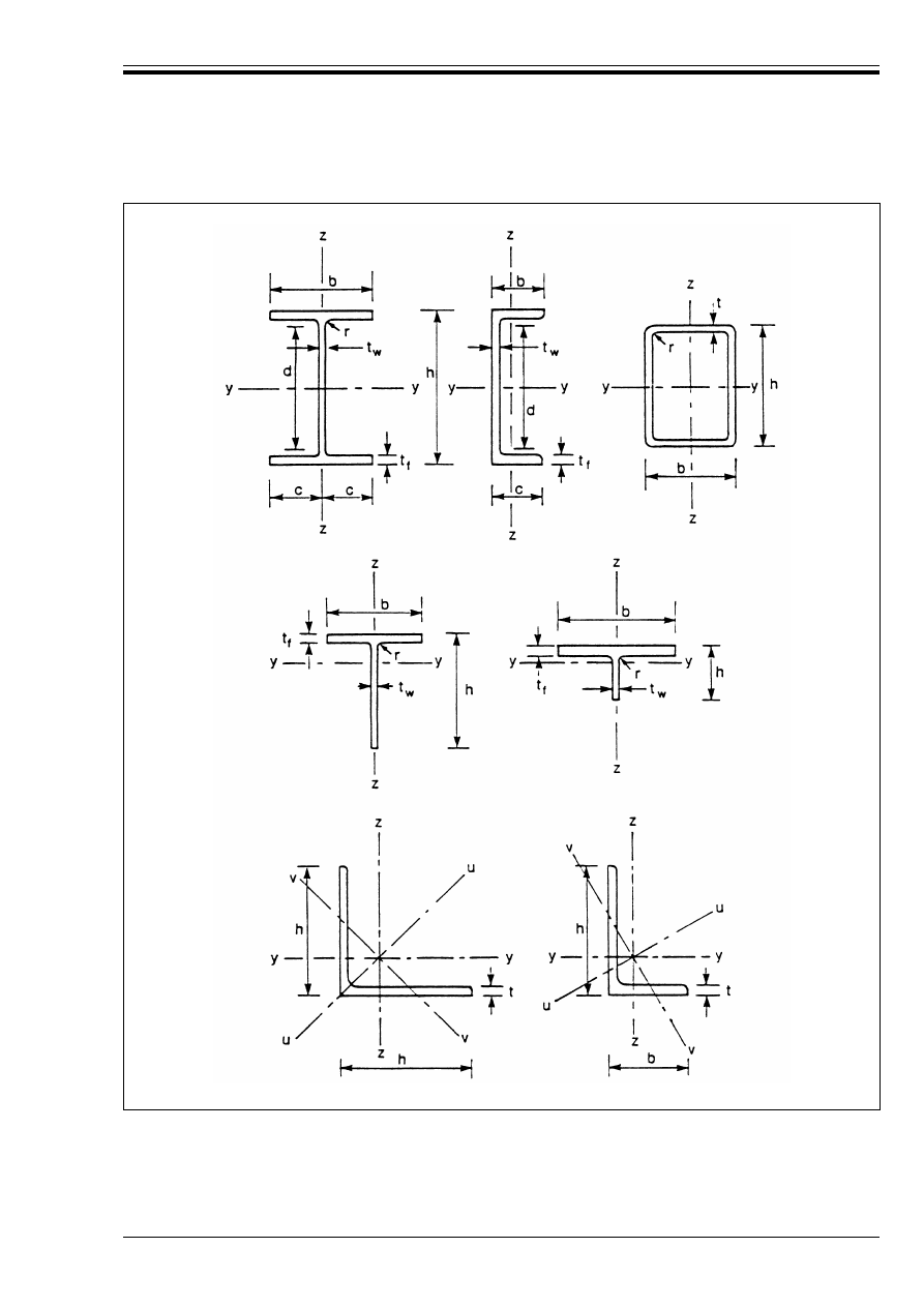
ENV 1993-1-1:1992
© BSI 04-2000
23
Figure 1.1 — Dimensions and axes of sections

ENV 1993-1-1:1992
24
© BSI 04-2000
2 Basis of design
2.1 Fundamental requirements
(1) A structure shall be designed and constructed in such a way that:
• with acceptable probability, it will remain fit for the use for which it is required, having due regard to
its intended life and its cost, and
• with appropriate degrees of reliability, it will sustain all actions and other influences likely to occur
during execution and use and have adequate durability in relation to maintenance costs.
(2) A structure shall also be designed in such a way that it will not be damaged by events like explosions,
impact or consequences of human errors, to an extent disproportionate to the original cause.
(3) The potential damage should be limited or avoided by appropriate choice of one or more of the following:
• avoiding, eliminating or reducing the hazards which the structure is to sustain
• selecting a structural form which has low sensitivity to the hazards considered
• selecting a structural form and design that can survive adequately the accidental removal of an
individual element
• tying the structure together
(4) The above requirements shall be met by the choice of suitable materials, by appropriate design and
detailing and by specifying control procedures for production, construction and use as relevant for the
particular project.
2.2 Definitions and classifications
2.2.1 Limit states and design situations
2.2.1.1 Limit states
(1) Limit states are states beyond which the structure no longer satisfies the design performance
requirements.
Limit states are classified into:
• ultimate limit states
• serviceability limit states.
(2) Ultimate limit states are those associated with collapse, or with other forms of structural failure which
may endanger the safety of people.
(3) States prior to structural collapse which, for simplicity, are considered in place of the collapse itself are
also classified and treated as ultimate limit states.
(4) Ultimate limit states which may require consideration include:
• loss of equilibrium of the structure or any part of it, considered as a rigid body,
• failure by excessive deformation, rupture, or loss of stability of the structure or any part of it, including
supports and foundations.
(5) Serviceability limit states correspond to states beyond which specified service criteria are no longer met.
(6) Serviceability limit states which may require consideration include:
• deformations or deflections which adversely affect the appearance or effective use of the structure
(including the proper functioning of machines or services) or cause damage to finishes or
non-structural elements
• vibration which causes discomfort to people, damage to the building or its contents, or which limits its
functional effectiveness.
2.2.1.2 Design situations
(1) Design situations are classified as:
• persistent situations corresponding to normal conditions of use of the structure
• transient situations, for example during construction or repair
• accidental situations.

ENV 1993-1-1:1992
© BSI 04-2000
25
2.2.2 Actions
2.2.2.1 Definitions and principal classification
5)
(1) An action (F) is:
• a force (load) applied to the structure (direct action), or
• an imposed deformation (indirect action); for example, temperature effects or settlement.
(2) Actions are classified:
i)
by their variation in time:
• permanent actions (G), e.g. self-weight of structures, fittings, ancilliaries and fixed equipment
• variable actions (Q), e.g. imposed loads, wind loads or snow loads
• accidental actions (A), e.g. explosions or impact from vehicles
ii) by their spatial variation:
• fixed actions, e.g. self-weight [but see 2.3.2.3(2) for structures very sensitive to variations in
self-weight]
• free actions, which result in different arrangements of actions, e.g. movable imposed loads, wind
loads, snow loads.
(3) Supplementary classifications relating to the response of the structure are given in the relevant clauses.
2.2.2.2 Characteristic values of actions
(1) Characteristic values F
k
are specified:
• in ENV 1991 Eurocode 1 or other relevant loading codes, or
• by the client, or the designer in consultation with the client, provided that the minimum provisions
specified in the relevant loading standards or by the competent authority are observed.
(2) For permanent actions where the coefficient of variation is large or where the actions are likely to vary
during the life of the structure (e.g. for some superimposed permanent loads), two characteristic values are
distinguished, an upper (G
k,sup
) and a lower (G
k,inf
). Elsewhere a single characteristic value (G
k
) is sufficient.
(3) The self-weight of the structure may, in most cases, be calculated on the basis of the nominal dimensions
and mean unit masses.
(4) For variable actions the characteristic value (Q
k
) corresponds to either:
• the upper value with an intended probability of not being exceeded, or the lower value with an
intended probability of not being reached, during some reference period, having regard to the intended
life of the structure or the assumed duration of the design situation, or
• the specified value.
(5) For accidental actions the characteristic value A
k
(when relevant) generally corresponds to a specified
value.
2.2.2.3 Representative values of variable actions
6)
(1) The main representative value is the characteristic value Q
k
.
(2) Other representative values are related to the characteristic value Q
k
by means of a factor Ò
i
.
These values are defined as:
(3) Supplementary representative values are used for fatigue verification and dynamic analysis.
(4) The factors Ò
0
, Ò
1
and Ò
2
are specified:
• in ENV 1991 Eurocode 1 or other relevant loading standards, or
• by the client, or the designer in consultation with the client, provided that the minimum provisions
specified in the relevant loading standards or by the competent authority are observed.
5)
Fuller definitions of the classification of actions will be found in ENV 1991 Eurocode 1.
6)
Fuller definitions of representative values will be found in ENV 1991 Eurocode 1.
w
combination value:
Ò
0
Q
k
(see 2.3.2.2)
w
frequent value:
Ò
1
Q
k
(see 2.3.4)
w
quasi-permanent value:
Ò
2
Q
k
(see 2.3.4)

ENV 1993-1-1:1992
26
© BSI 04-2000
2.2.2.4 Design values of actions
(1) The design value F
d
of an action is expressed in general terms as:
where ¾
F
is the partial safety factor for the action considered — taking account of, for example, the
possibility of unfavourable deviations of the actions, the possibility of inaccurate modelling of the actions,
uncertainties in the assessment of effects of actions and uncertainties in the assessment of the limit state
considered.
(2) Specific examples of the use of ¾
F
are:
(3) The upper and lower design values of permanent actions are expressed as follows:
• where only a single characteristic value G
k
is used [see 2.2.2.2(2)] then:
• where upper and lower characteristic values of permanent actions are used [see 2.2.2.2(2)] then:
2.2.2.5 Design values of the effects of actions
(1) The effects of actions (E) are responses (for example, internal forces and moments, stresses, strains) of
the structure to the actions. Design values of the effects of actions (E
d
) are determined from the design
values of the actions, geometrical data and material properties when relevant:
2.2.3 Material properties
2.2.3.1 Characteristic values
(1) A material property is represented by a characteristic value X
k
which in general corresponds to a fractile
in the assumed statistical distribution of the particular property of the material, specified by relevant
standards and tested under specified conditions.
(2) In certain cases a nominal value is used as the characteristic value.
(3) Material properties for steel structures are generally represented by nominal values used as
characteristic values.
(4) A material property may have two characteristic values, the upper value and the lower value. In most
cases only the lower value need be considered. However, higher values of the yield strength, for example,
should be considered in special cases where overstrength effects may produce a reduction in safety.
2.2.3.2 Design values
(1) The design value X
d
of a material property is generally defined as:
X
d
= X
k
/¾
M
where ¾
M
is the partial safety factor for the material property.
(2) For steel structures, the design resistance R
d
is generally determined directly from the characteristic
values of the material properties and geometrical data:
F
d
= ¾
F
F
k
(2.1)
G
d
=
¾
G
G
k
Q
d
=
¾
Q
Q
k
or ¾
Q
Ò
i
Q
k
A
d
=
¾
A
A
k
(if A
d
is not directly specified)
G
d,sup
=
¾
G,sup
G
k
G
d,inf
=
¾
G,inf
G
k
G
d,sup
=
¾
G,sup
G
k,sup
G
d,inf
=
¾
G,inf
G
k,inf
where G
k,inf
is the lower characteristic value of the permanent action
G
k,sup
is the upper characteristic value of the permanent action
¾
G,inf
is the lower value of the partial safety factor for the permanent action
¾
G,sup
is the upper value of the partial safety factor for the permanent action
E
d
= E(F
d
, a
d
....)
(2.2)
where a
d
is defined in 2.2.4.
R
d
= R (X
k
, a
k
, ...)/¾
M
(2.3)

ENV 1993-1-1:1992
© BSI 04-2000
27
(3) The design value R
d
may be determined from tests. Guidance is given in Chapter 8.
2.2.4 Geometrical data
(1) Geometrical data are generally represented by their nominal values:
(2) In some cases the geometrical design values are defined by:
The values of %a are given in the appropriate clauses.
(3) For imperfections to be adopted in the global analysis of the structure, see 5.2.4.
2.2.5 Load arrangements and load cases
7)
(1) A load arrangement identifies the position, magnitude and direction of a free action.
(2) A load case identifies compatible load arrangements, sets of deformations and imperfections considered
for a particular verification.
2.3 Design requirements
2.3.1 General
(1) It shall be verified that no relevant limit state is exceeded.
(2) All relevant design situations and load cases shall be considered.
(3) Possible deviations from the assumed directions or positions of actions shall be considered.
(4) Calculations shall be performed using appropriate design models (supplemented, if necessary, by tests)
involving all relevant variables. The models shall be sufficiently precise to predict the structural behaviour,
commensurate with the standard of workmanship likely to be achieved, and with the reliability of the
information on which the design is based.
2.3.2 Ultimate limit states
2.3.2.1 Verification conditions
(1) When considering a limit state of static equilibrium or of gross displacements or deformations of the
structure, it shall be verified that:
(2) When considering a limit state of rupture or excessive deformation of a section, member or connection
(fatigue excluded) it shall be verified that:
(3) When considering a limit state of transformation of the structure into a mechanism, it shall be verified
that a mechanism does not occur unless actions exceed their design values, taking account of the respective
design values of all structural properties.
(4) When considering a limit state of stability induced by second-order effects, it shall be verified that
instability does not occur unless actions exceed their design values, taking account of the respective design
values of all structural properties. In addition, sections shall be verified according to (2) above.
(5) When considering a limit state of rupture induced by fatigue, it shall be verified that the design value
of the damage indicator D
d
does not exceed unity, see Chapter 9.
where y
M
is the partial safety factor for the resistance.
a
d
= a
nom
(2.4)
a
d
= a
nom
+ %a
(2.5)
7)
Detailed rules on load arrangements and load cases are given in ENV 1991 Eurocode 1.
E
d,dst
k E
d,stb
(2.6)
where
E
d,dst
is the design effect of the destabilizing actions
and
E
d,stb
is the design effect of the stabilizing actions.
S
d
k R
d
(2.7)
where S
d
is the design value of an internal force or moment (or of a respective vector of several
internal forces or moments)
and
R
d
is the corresponding design resistance,
each taking account of the respective design values of all structural properties.
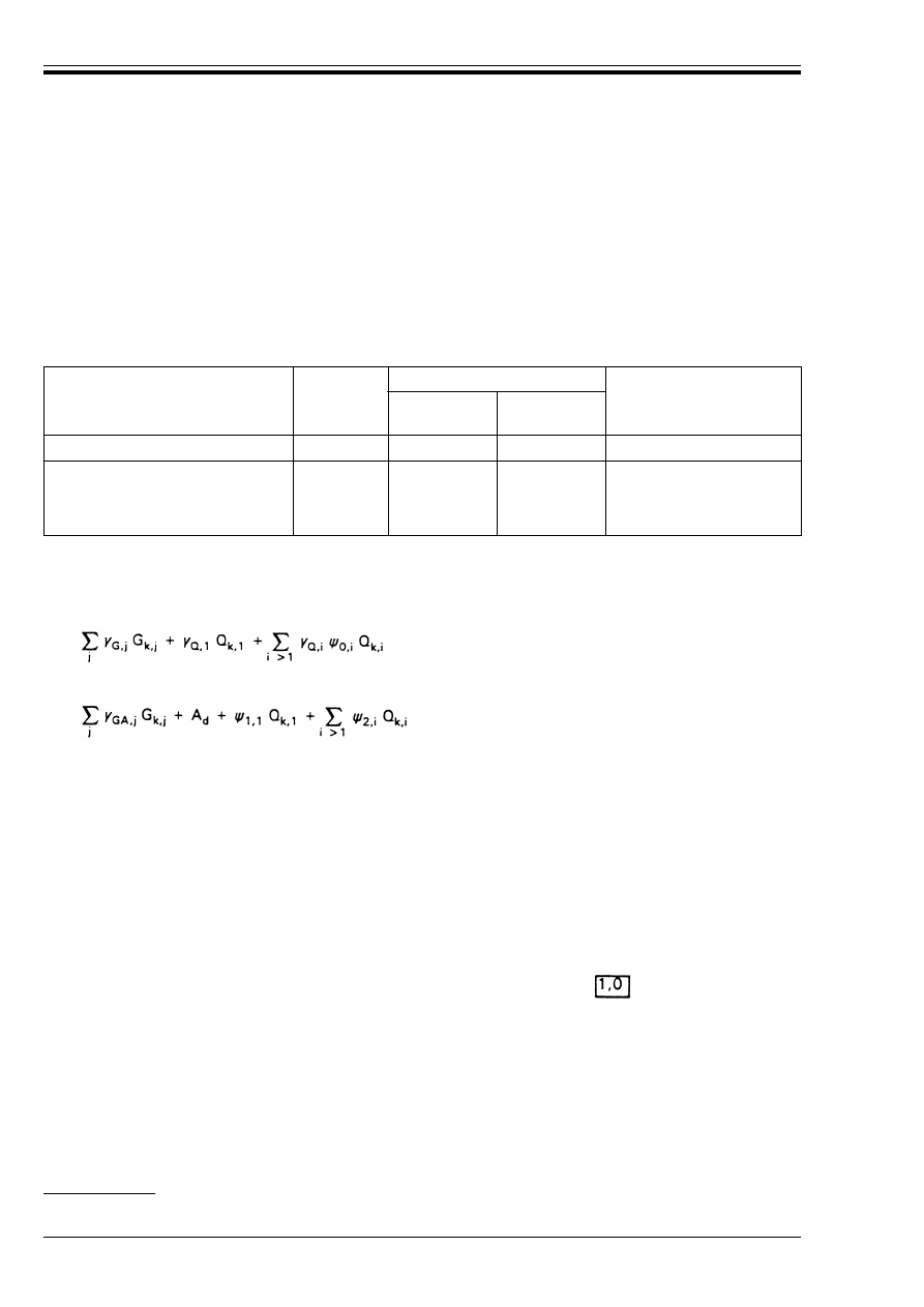
ENV 1993-1-1:1992
28
© BSI 04-2000
(6) When considering effects of actions, it shall be verified that:
2.3.2.2 Combinations of actions
(1) For each load case, design values E
d
for the effects of actions shall be determined from combination rules
involving the design values of actions given in Table 2.1.
Table 2.1 — Design values of actions for use in the combination of actions
(2) The design values given in Table 2.1 shall be combined using the following rules (given in symbolic
form):
8)
• Persistent and transient design situations for verifications other than those relating to fatigue
(fundamental combinations):
• Accidental design situations (if not specified differently elsewhere):
(3) Combinations for accidental design situations either involve an explicit accidental action A or refer to a
situation after an accidental event (A = 0). Unless specified otherwise, ¾
GA
= may be used.
(4) In expressions (2.9) and (2.10), indirect actions shall be introduced where relevant.
(5) For fatigue, see Chapter 9.
(6) Simplified combinations for building structures are given in 2.3.3.1.
E
d
k C
d
(2.8)
where E
d
is the design value of the particular effect of actions being considered
and
C
d
is the design capacity for that effect of actions.
Design situation
Permanent
actions G
d
Variable actions Q
d
Accidental actions A
d
Leading
variable action
Accompanying
variable action
Persistent and Transient
¾
G
G
k
¾
Q
Q
k
Ò
0
¾
Q
Q
k
Accidental
(if not specified
differently elsewhere)
¾
GA
G
k
Ò
1
Q
k
Ò
2
Q
k
¾
A
A
k
(if A
d
is not specified
directly)
8)
Detailed rules on combinations of actions are given in ENV 1991 Eurocode 1.
(2.9)
(2.10)
where:
G
k,j
are the characteristic values of the permanent actions
Q
k,1
is the characteristic value of one of the variable actions
Q
k,i
are the characteristic values of the other variable actions
A
d
is the design value (specified value) of the accidental action
¾
G,j
is the partial safety factor for the permanent action G
k,j
¾
GA,j
is as ¾
G,j
but for accidental design situations
¾
Q,i
is the partial safety factor for the variable action Q
k,i
and Ò
0
, Ò
1
, Ò
2
are factors defined in 2.2.2.3.

ENV 1993-1-1:1992
© BSI 04-2000
29
2.3.2.3 Design values of permanent actions
(1) In the various combinations defined above, those permanent actions that increase the effect of the
variable actions (i.e. produce unfavourable effects) shall be represented by their upper design values and
those that decrease the effect of the variable actions (i.e. produce favourable effects) by their lower design
values [see 2.2.2.4(3)].
(2) Where the results of a verification may be very sensitive to variations of the magnitude of a single
permanent action from place to place in the structure, this action shall be treated as consisting of separate
unfavourable and favourable parts. This applies in particular to the verification of static equilibrium,
see 2.3.2.4.
(3) Where a single permanent action is treated as consisting of separate unfavourable and favourable parts,
allowance may be made for the relationship between these parts by adopting special design values
[see 2.3.3.1(3) for building structures].
(4) Except for the cases mentioned in (2), the whole of each permanent action should be represented
throughout the structure by either its lower or its upper design value, whichever gives the more unfavourable
effect.
(5) For continuous beams and frames, the same design value of the self-weight of the structure [evaluated as
in 2.2.2.2(3)] may be applied to all spans, except for cases involving the static equilibrium of cantilevers
(see 2.3.2.4).
2.3.2.4 Verification of static equilibrium
(1) For the verification of static equilibrium, destabilizing (unfavourable) actions shall be represented by
upper design values and stabilizing (favourable) actions by lower design values [see 2.3.2.1(1)].
(2) For stabilizing effects, only those actions which can reliably be assumed to be present in the situation
considered shall be included in the relevant combination.
(3) Variable actions should be applied where they increase the destabilizing effects but omitted where they
would increase the stabilizing effects.
(4) Account should be taken of the possibility that non-structural elements might be omitted or removed.
(5) Permanent actions shall be represented by appropriate design values, depending on whether the
destabilizing and stabilizing effects result from:
• the unfavourable and the favourable parts of a single permanent action, see (9) below, and/or
• different permanent actions, see (10) below.
(6) The self-weights of any unrelated structural or non-structural elements made of different construction
materials should be treated as different permanent actions.
(7) The self-weight of a homogeneous structure should be treated as a single permanent action consisting of
separate unfavourable and favourable parts.
(8) The self-weights of essentially similar parts of a structure (or of essentially uniform non-structural
elements) may also be treated as separate unfavourable and favourable parts of a single permanent action.
(9) For building structures, the special partial safety factors given in 2.3.3.1(3) apply to the unfavourable
and the favourable parts of each single permanent action, as envisaged in 2.3.2.3(2).
(10) For building structures, the normal partial safety factors given in 2.3.3.1(1) apply to permanent
actions other than those covered by (9).
(11) For closely bounded or closely controlled permanent actions, smaller ratios of partial safety factors may
apply in the other Parts of Eurocode 3.
(12) Where uncertainty of the value of a geometrical dimension significantly affects the verification of static
equilibrium, this dimension shall be represented in this verification by the most unfavourable value that
it is reasonably possible for it to reach.
2.3.3 Partial safety factors for ultimate limit states
2.3.3.1 Partial safety factors for actions on building structures
(1) For the persistent and transient design situations the partial safety factors given in Table 2.2 shall be
used.
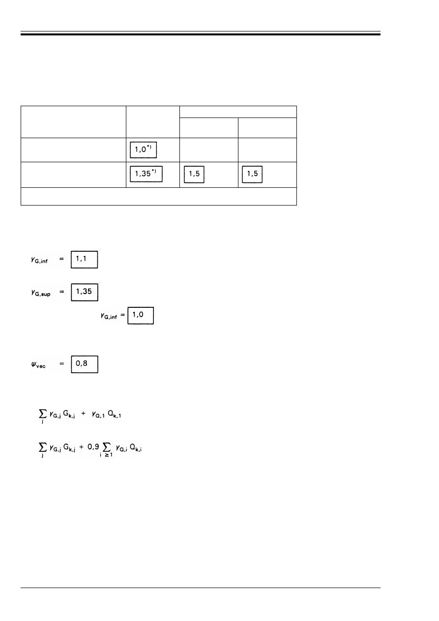
ENV 1993-1-1:1992
30
© BSI 04-2000
Table 2.2 — Partial safety factors for actions on building structures
for persistent and transient design situations
(2) For accidental design situations to which expression (2.10) applies, the partial safety factors for the
variable actions are taken as equal to 1,0.
(3) Where, according to 2.3.2.3(2), a single permanent action needs to be considered as consisting of
unfavourable and favourable parts, the favourable part may, as an alternative, be multiplied by:
and the unfavourable part by:
provided that applying
both to the favourable part and to the unfavourable part does not
give a more unfavourable effect.
(4) Where the components of a vectorial effect can vary independently, favourable components
(eg. the longitudinal force) should be multiplied by a reduction factor:
(5) For building structures, as a simplification, expression (2.9) may be replaced by whichever of the
following combinations gives the larger value:
• considering only the most unfavourable variable action:
• considering all unfavourable variable actions:
2.3.3.2 Partial safety factors for resistances
(1) Partial safety factors for resistances are given in the relevant clauses in Chapters 5 and 6.
(2) Where structural properties are determined by testing see Chapter 8.
(3) For fatigue verifications see Chapter 9.
2.3.4 Serviceability limit states
(1) It shall be verified that:
Permanent
actions (
¾
G
)
Variable actions (
¾
Q
)
Leading variable
action
Accompanying
variable actions
Favourable effect ¾
F,inf
**)
**)
Unfavourable effect ¾
F,sup
*) See also 2.3.3.1(3)
**) See Eurocode 1; in normal cases for building structures ¾
Q,inf
= 0.
(2.11)
(2.12)
E
d
k C
d
or E
d
k R
d
(2.13)
where:
C
d
is a nominal value or a function of certain design properties of materials related to the design
effect of actions considered, and
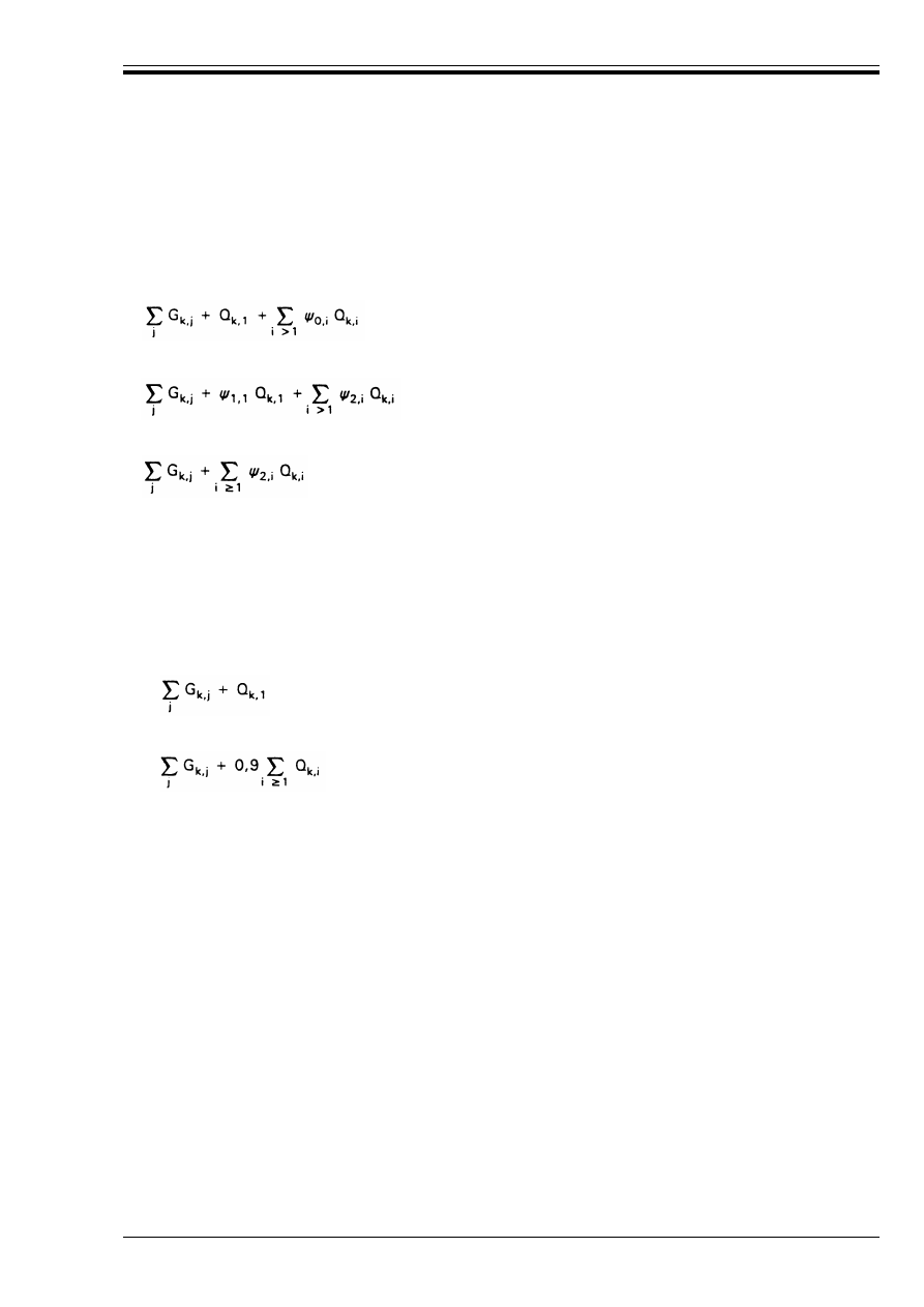
ENV 1993-1-1:1992
© BSI 04-2000
31
The required combination is identified in the particular clause for each serviceability verification,
see 4.2.1(4) and 4.3.1(4).
(2) Three combinations of actions for serviceability limit states are defined by the following expressions:
Rare combination:
Frequent combination:
Quasi-permanent combination:
where the notation is defined in 2.3.2.2(2)
(3) Where simplified compliance rules are given in the relevant clauses dealing with serviceability limit
states, detailed calculations using combinations of actions are not required.
(4) Where the design considers compliance of serviceability limit states by detailed calculations, simplified
expressions may be used for building structures.
(5) For building structures, as a simplification, expression (2.14) for the rare combination may be replaced
by whichever of the following combinations gives the larger value:
• considering only the most unfavourable variable action:
• considering all unfavourable variable actions:
These two expressions may also be used as a substitute for expression (2.15) for the frequent combination.
(6) Values of ¾
M
shall be taken as 1,0 for all serviceability limit states, except where stated otherwise in
particular clauses.
2.4 Durability
(1) To ensure an adequately durable structure, the following inter-related factors shall be considered:
• the use of the structure
• the required performance criteria
• the expected environmental conditions
• the composition, properties and performance of the materials
• the shape of members and the structural detailing
• the quality of workmanship and level of control
• the particular protective measures
• the likely maintenance during the intended life.
(2) The internal and external environmental conditions shall be estimated at the design stage to assess
their significance in relation to durability and to enable adequate provisions to be made for protection of
the materials.
E
d
is the design effect of actions, determined on the basis of one of the combinations defined below.
(2.14)
(2.15)
(2.16)
(2.17)
(2.18)
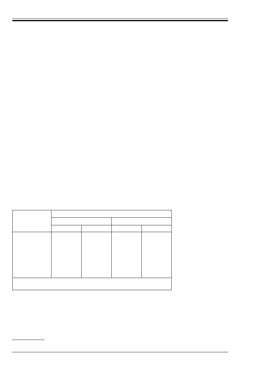
ENV 1993-1-1:1992
32
© BSI 04-2000
2.5 Fire resistance
(1) For fire resistance, refer to ENV 1993-1-2 Eurocode 3-1.2
9)
.
3 Materials
3.1 General
(1) The material properties given in this Chapter are nominal values to be adopted as characteristic values
in design calculations.
(2) Other material properties are given in the relevant Reference Standards defined in normative
Annex B.
3.2 Structural steel
3.2.1 Scope
(1) This Part 1.1 of Eurocode 3 covers the design of structures fabricated from steel material conforming to
Reference Standard 1, see normative Annex B.
(2) It may also be used for other structural steels, provided that adequate data exist to justify the
application of the relevant design and fabrication rules. Test procedures and test evaluation shall conform
with Chapters 2 and 8 of this Part 1.1 and the test requirements shall align with those required in
Reference Standard 1.
(3) For high strength steel refer to normative Annex D
9)
.
3.2.2 Material properties for hot rolled steel
3.2.2.1 Nominal values
(1) The nominal values of the yield strength f
y
and the ultimate tensile strength f
u
for hot rolled steel are
given in Table 3.1 for steel grades Fe 360, Fe 430 and Fe 510 in accordance with EN 10025 and steel grades
Fe E 275 and Fe E 355 in accordance with prEN 10113.
Table 3.1 — Nominal values of yield strength f
y
and ultimate tensile
strength f
u
for structural steel to EN 10025 or prEN 10113
(2) The nominal values in Table 3.1 may be adopted as characteristic values in calculations.
(3) As an alternative, the values specified in EN 10025 and prEN 10113 for a larger range of thicknesses
may be used.
(4) Similar values may be adopted for hot finished structural hollow sections.
(5) For high strength steel refer to normative Annex D
9)
.
9)
In preparation
Nominal steel
grade
Thickness
t mm
a
t k 40 mm
40 mm < t k 100 mm
b
f
y
(N/mm
2
)
f
u
(N/mm
2
)
f
y
(N/mm
2
)
f
u
(N/mm
2
)
EN 10025:
Fe 360
Fe 430
Fe 510
prEN 10113:
Fe E 275
Fe E 355
235
275
355
275
355
360
430
510
390
490
215
255
335
255
335
340
410
490
370
470
a
t is the nominal thickness of the element.
b
63 mm for plates and other flat products in steels of delivery condition TM to prEN 10113-3

ENV 1993-1-1:1992
© BSI 04-2000
33
3.2.2.2 Plastic analysis
(1) Plastic analysis (see 5.2.1.4) may be utilised in the global analysis of structures or their elements
provided that the steel complies with the following additional requirements:
• the ratio of the specified minimum ultimate tensile strength f
u
to the specified minimum yield
strength f
y
satisfies:
f
u
/f
y
U 1,2
• the elongation at failure on a gauge length of 5,65 ÆA
o
(where A
o
is the original cross section area) is
not less than 15 %
• the stress-strain diagram shows that the ultimate strain ¼
u
corresponding to the ultimate tensile
strength f
u
is at least 20 times the yield strain ¼
y
corresponding to the yield strength f
y
.
(2) The steel grades listed in Table 3.1 may be accepted as satisfying these requirements.
3.2.2.3 Fracture toughness
(1) The material shall have sufficient fracture toughness to avoid brittle fracture at the lowest service
temperature expected to occur within the intended life of the structure.
(2) In normal cases of welded or non-welded members in building structures subject to static loading or
fatigue loading (but not impact loading), no further check against brittle fracture is necessary if the
conditions given in Table 3.2 are satisfied.
(3) For high strength steel refer to normative Annex D.
(4) For all other cases reference should be made to informative Annex C.
3.2.3 Material properties for cold formed steel
(1) The nominal values of the yield strength and the ultimate tensile strength (to be adopted as
characteristic values in calculations) for cold formed steel are specified in ENV 1993-1-3
Eurocode 3-1.3
10)
.
(2) The average yield strength of cold finished structural hollow sections shall be determined as specified
in Figure 5.5.2.
3.2.4 Dimensions, mass and tolerances
(1) The dimensions and mass of all rolled steel sections, plates and structural hollow sections, and their
dimensional and mass tolerances, shall conform with Reference Standard 2, see normative Annex B.
3.2.5 Design values of material coefficients
(1) The material coefficients to be adopted in calculations for the steels covered by this Eurocode shall be
taken as follows:
10)
In preparation
w
modulus of elasticity
E = 210 000 N/mm
2
w
shear modulus
G = E/2(1 + É)
w
Poisson’s ratio
É = 0,3
w
coefficient of linear thermal expansion µ = 12 × 10
–6
per °C
w
unit mass
Ô = 7 850 kg/m
3
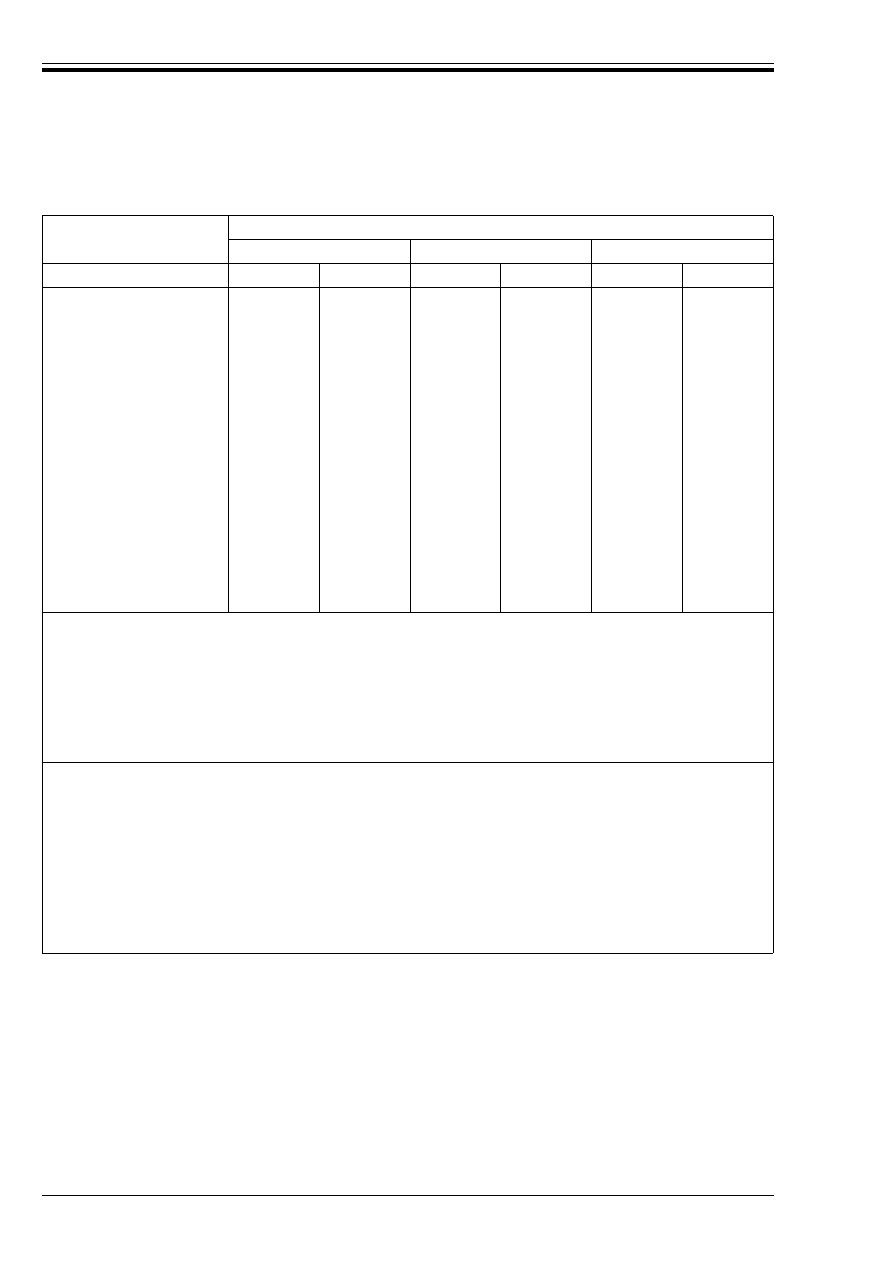
ENV 1993-1-1:1992
34
© BSI 04-2000
Table 3.2 — Maximum thickness for statically loaded structural elements without
reference to informative Annex C
3.3 Connecting devices
3.3.1 General
(1) Connecting devices shall be suitable for their specified use.
(2) Suitable connecting devices include bolts, friction grip fasteners, rivets and welds, each to the appropriate
Reference Standard, see normative Annex B.
Steel grade and quality
Maximum thickness (mm) for lowest service temperature of
0 °C
– 10 °C
– 20 °C
Service condition
S1
S2
S1
S2
S1
S2
EN 10025
(1)
:
Fe 360 B
Fe 360 C
Fe 360 D
Fe 430 B
Fe 430 C
Fe 430 D
Fe 510 B
Fe 510 C
Fe 510 D
Fe 510 DD
(2)
prEN 10113:
(3)
Fe E 275 KG
(4)
Fe E 275 KT
Fe E 355 KG
(4)
Fe E 355 KT
150
250
250
90
250
250
40
106
250
250
250
250
250
250
41
110
250
26
63
150
12
29
73
128
250
250
128
250
108
250
250
63
150
250
29
73
177
250
250
250
250
250
30
75
212
19
45
127
9
21
52
85
192
250
85
250
74
187
250
45
123
250
21
52
150
250
250
250
250
250
22
53
150
14
33
84
6
16
38
59
150
250
59
150
Service conditions
(5)
:
S1
S2
Either:
• non-welded, or
• in compression
As welded, in tension
In both cases this table assumes loading rate R1 and consequences of failure condition C2,
see informative Annex C.
Notes:
(1) For rolled sections over 100 mm thick, the minimum Charpy V-notch energy specified in EN 10025 is subject to agreement. For
thicknesses up to 150 mm, a minimum value of 27 J at the relevant specified test temperature is required and 23 J for thicknesses
over 150 mm up to 250 mm.
(2) For steel grade Fe 510 DD to EN 10025, the specified minimum Charpy V-notch energy value is 40 J at – 20 °C. The entries in
this row assume an equivalent value of 27 J at – 30 °C.
(3) For steels of delivery condition N to prEN 10113-2 over 150 mm thick and for steels of delivery condition TM to prEN 10113-3
over 150 mm thick for long products and over 63 mm thick for flat products, the minimum Charpy V-notch energy specified in
prEN 10113 is subject to agreement. For thicknesses up to 150 mm, a minimum value of 27 J is required and 23 J for thicknesses
over 150 mm up to 250 mm. The test temperature should be – 30 °C for KG quality steel and – 50 °C for KT quality steel.
(4) For steel of quality KG to prEN 10113, the specified minimum values of Charpy V-notch energy go down to 40 J at – 20 °C. The
entries in this row assume an equivalent value of 27 J at – 30 °C.
(5) For full details of service conditions, refer to informative Annex C.
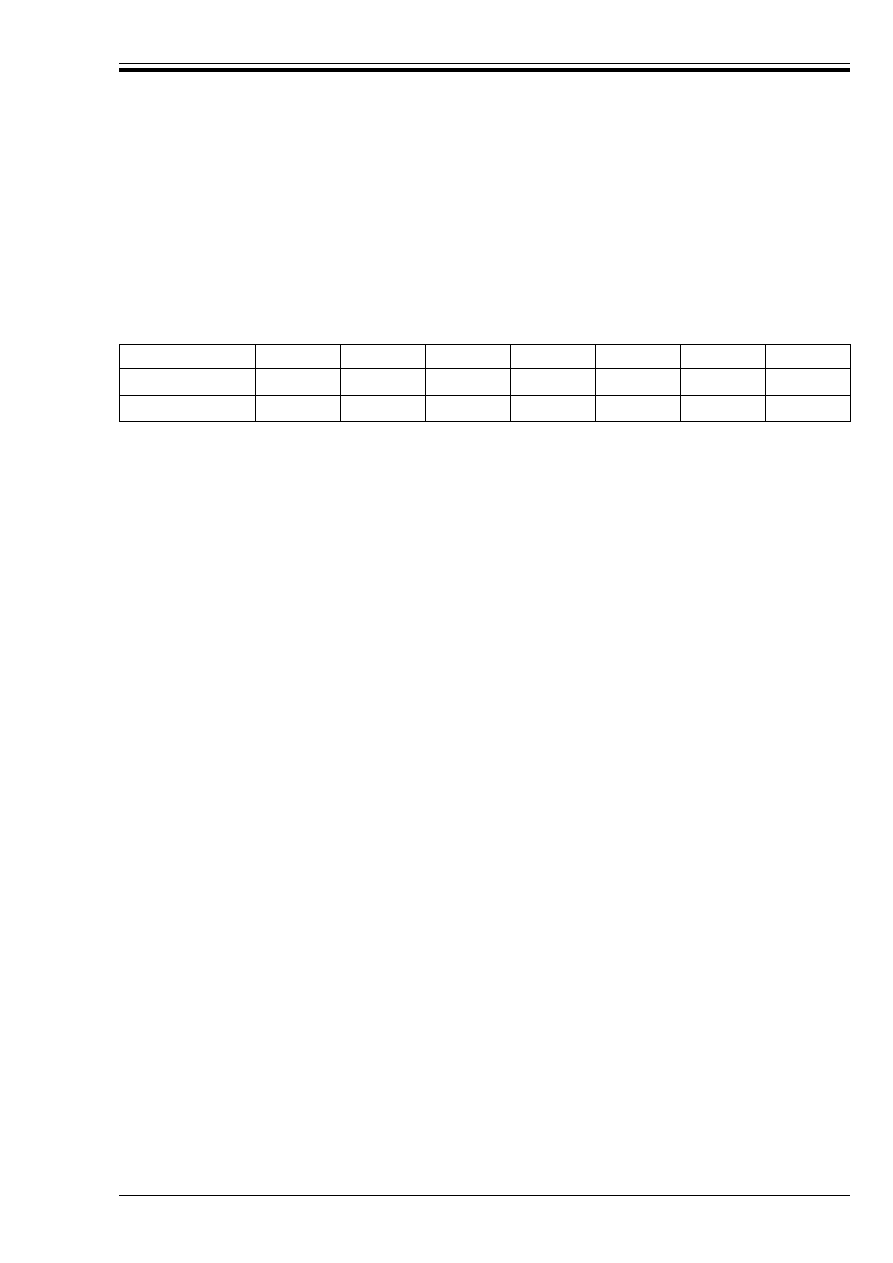
ENV 1993-1-1:1992
© BSI 04-2000
35
3.3.2 Bolts, nuts and washers
3.3.2.1 General
(1) Bolts, nuts and washers shall conform with Reference Standard 3, see normative Annex B.
(2) Bolts of grades lower than 4.6 or higher than 10.9 shall not be used unless test results prove their
acceptability in a particular application.
(3) The nominal values of the yield strength f
yb
and the ultimate tensile strength f
ub
(to be adopted as
characteristic values in calculations) are given in Table 3.3.
Table 3.3 — Nominal values of yield strength f
yb
and ultimate tensile strength f
ub
for bolts
3.3.2.2 Preloaded bolts
(1) High strength bolts may be used as preloaded bolts with controlled tightening, if they conform with the
requirements for preloaded bolts in Reference Standard 3.
(2) Other suitable types of high strength bolts may also be used as preloaded bolts with controlled
tightening, when agreed between the client, the designer and the competent authority.
3.3.3 Other types of preloaded fasteners
(1) Other suitable types of high strength fasteners (such as high strength swaged fasteners) may also be
used as preloaded fasteners, when agreed between the client, the designer and the competent authority,
provided that they have similar mechanical properties to those required for preloaded bolts and are capable
of being reliably tightened to appropriate specified initial preloads.
3.3.4 Rivets
(1) The material properties, dimensions and tolerances of steel rivets shall conform with Reference
Standard 5, see normative Annex B.
3.3.5 Welding consumables
(1) All welding consumables shall conform with Reference Standard 4, see normative Annex B.
(2) The specified yield strength, ultimate tensile strength, elongation at failure and minimum
Charpy V-notch energy value of the filler metal, shall all be either equal to, or better than, the
corresponding values specified for the steel grade being welded.
4 Serviceability limit states
4.1 Basis
(1) Serviceability limit states, see also 2.2.1.1, for steelwork are:
• deformations or deflections which adversely affect the appearance or effective use of the structure
(including the proper functioning of machines or services)
• vibration, oscillation or sway which causes discomfort to the occupants of a building or damage to its
contents
• deformations, deflections, vibration, oscillation or sway which causes damage to finishes or
non-structural elements.
(2) To avoid exceeding these limits, it is necessary to limit deformations, deflections and vibrations.
(3) Except when specific limiting values are agreed between the client, the designer and the competent
authority, the limiting values given in this Chapter should be applied.
(4) When plastic global analysis is used for the ultimate limit state, the possibility that plastic redistribution
of forces and moments would also occur at the serviceability limit state should be investigated. This should
be permitted only where it can be shown that it will not be repeated. It should also be taken into account in
calculating the deformations.
(5) Where preloaded bolts are used in Category B connections [see 6.5.3.1(3)] the requirements given
in 6.5.8 for slip-resistance at the serviceability limit state shall be satisfied.
Bolt grade
4.6
4.8
5.6
5.8
6.8
8.8
10.9
f
yb
(N/mm
2
)
240
320
300
400
480
640
900
f
ub
(N/mm
2
)
400
400
500
500
600
800
1 000

ENV 1993-1-1:1992
36
© BSI 04-2000
4.2 Deflections
4.2.1 Requirements
(1) Steel structures and components shall be so proportioned that deflections are within the limits agreed
between the client, the designer and the competent authority as being appropriate to the intended use and
occupancy of the building and the nature of the materials to be supported.
(2) Recommended limits for deflections are given in 4.2.2. In some cases more stringent limits
(or exceptionally, less stringent limits) will be appropriate to suit the use of the building or the characteristics
of the cladding materials or to ensure the proper operation of lifts etc.
(3) The values given in 4.2.2 are empirical values. They are intended for comparison with the results of
calculations and should not be interpreted as performance criteria.
(4) The design values given in 2.3.4 for the rare combination should be used in connection with all limiting
values given in section 4.2.
(5) The deflections should be calculated making due allowance for any second order effects, the rotational
stiffness of any semi-rigid joints and the possible occurrence of any plastic deformations at the serviceability
limit state.
4.2.2 Limiting values
(1) The limiting values for vertical deflections given below are illustrated by reference to the simply
supported beam shown in Figure 4.1, in which:
(2) For buildings, the recommended limits for vertical deflections are given in Table 4.1, in which L is the
span of the beam. For cantilever beams, the length L to be considered is twice the projecting length of the
cantilever.
(3) For crane gantry girders and runway beams, the horizontal and vertical deflections should be limited
according to the use and class of the equipment.
(4) For buildings the recommended limits for horizontal deflections at the tops of the columns are:
4.2.3 Ponding
(1) To ensure the correct discharge of rainwater from a flat or nearly flat roof, the design of all roofs with a
slope of less than 5 % should be checked to ensure that rainwater cannot collect in pools. In this check, due
allowance should be made for possible construction inaccuracies and settlements of foundations, deflections
of roofing materials, deflections of structural members and the effects of precamber. This also applies to
floors of car parks and other open sided structures.
(2) Precambering of beams may reduce the likelihood of rainwater collecting in pools, provided that
rainwater outlets are appropriately located.
¸
max
= ¸
1
+ ¸
2
Ð ¸
0
(4.1)
where ¸
max
is the sagging in the final state relative to the straight line joining the supports.
¸
0
is the pre-camber (hogging) of the beam in the unloaded state, (state 0).
¸
1
is the variation of the deflection of the beam due to the permanent loads immediately
after loading, (state 1).
and
¸
2
is the variation of the deflection of the beam due to the variable loading plus any time
dependent deformations due to the permanent load, (state 2).
w
Portal frames without gantry cranes:
h/150
w
Other single storey buildings:
h/300
w
In a multistorey building:
w
In each storey
h/300
w
On the structure as a whole
h
o
/500
where h is the height of the column or of the storey
and
h
o
is the overall height of the structure.
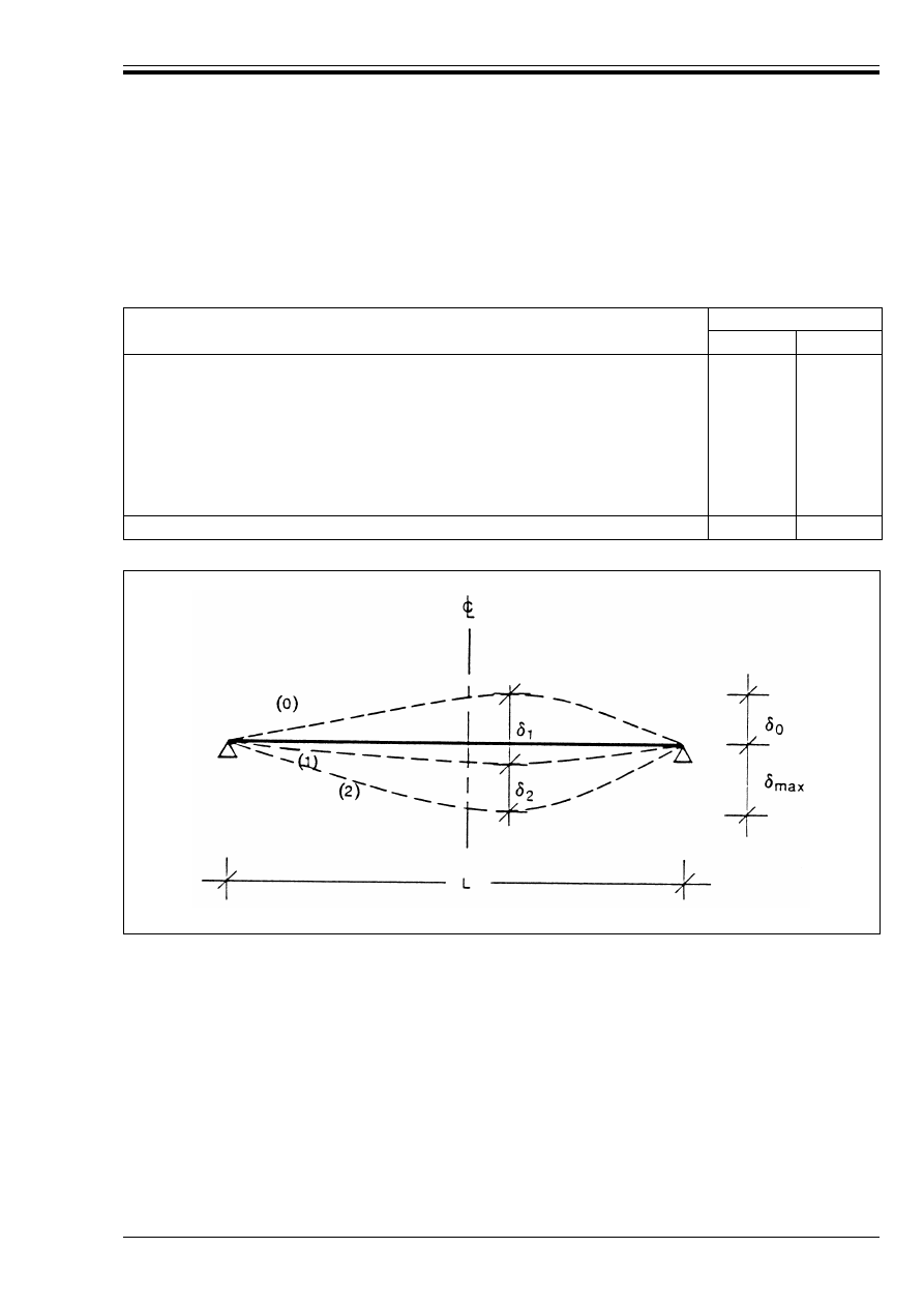
ENV 1993-1-1:1992
© BSI 04-2000
37
(3) Where the roof slope is less than 3 % additional calculations should be made to check that collapse cannot
occur due to the weight of water:
• either collected in pools which may be formed due to the deflection of structural members or roofing
material
• or retained by snow.
Table 4.1 — Recommended limiting values for vertical deflections
4.3 Dynamic effects
4.3.1 Requirements
(1) Suitable provisions shall be made in the design for the effects of imposed loads which can induce impact,
vibration, etc.
(2) The dynamic effects to be considered at the serviceability limit state are vibration caused by machines
and oscillation caused by harmonic resonance.
(3) The natural frequencies of structures or parts of structures should be sufficiently different from those of
the excitation source to avoid resonance.
(4) The design values given in 2.3.4 for the frequent combination should be used in connection with all
limiting values given in section 4.3.
Conditions
Limits (see Figure 4.1)
¸
max
¸
2
Roofs generally
Roofs frequently carrying personnel other than for maintenance
Floors generally
Floors and roofs supporting plaster or other brittle finish or non-flexible
partitions
Floors supporting columns (unless the deflection has been included in the
global analysis for the ultimate limit state)
L/200
L/250
L/250
L/250
L/400
L/250
L/300
L/300
L/350
L/500
Where ¸
max
can impair the appearance of the building
L/250
—
Figure 4.1 — Vertical deflections to be considered

ENV 1993-1-1:1992
38
© BSI 04-2000
4.3.2 Structures open to the public
(1) The oscillation and vibration of structures on which the public can walk shall be limited to avoid
significant discomfort to users.
(2) In the case of floors over which people walk regularly, such as the floors of dwellings, offices and the like,
the lowest natural frequency of the floor construction should not be lower than 3 cycles/second. This
condition will be satisfied if the instantaneous total deflection ¸
1
+ ¸
2
(as defined in 4.2.2 but calculated
using the frequent combination) is less than 28 mm. These limits may be relaxed where justified by high
damping values.
(3) In the case of a floor which is jumped or danced on in a rhythmical manner, such as the floor of a
gymnasium or dance hall, the lowest natural frequency of that floor should not be less
than 5 cycles/second. This condition will be satisfied if the deflection calculated as above is not greater
than 10 mm.
(4) If necessary, a dynamic analysis may be carried out to show that the accelerations and frequencies which
would be produced would not be such as to cause significant discomfort to users or damage to equipment.
4.3.3 Wind — excited oscillations
(1) Unusually flexible structures, such as very slender tall buildings or very large roofs, and unusually
flexible elements, such as light tie rods, shall be investigated under dynamic wind loads both for vibrations
in plane and also for vibrations normal to the wind direction.
(2) Such structures should be examined for:
• gust induced vibrations
• vortex induced vibrations
(3) See also ENV 1991 Eurocode 1
11)
.
5 Ultimate limit states
5.1 Basis
5.1.1 General
(1) Steel structures and components shall be so proportioned that the basic design requirements for the
ultimate limit state given in Chapter 2 are satisfied.
(2) The partial safety factor ¾
M
shall be taken as follows:
5.1.2 Frame design
(1) Frames shall be checked for:
• resistance of cross-sections (5.4)
• resistance of members (5.5)
• resistance of connections (Chapter 6)
• frame stability (5.2.6)
• static equilibrium (2.3.2.4)
11)
In preparation
w
resistance of Class 1, 2 or 3 cross-section:
a
¾
M0
=
w
resistance of Class 4 cross-section:
a
¾
M1
=
w
resistance of member to buckling:
¾
M1
=
w
resistance of net section at bolt holes:
¾
M2
=
w
resistance of connections:
see Chapter 6
a
For classification of cross-sections see 5.3

ENV 1993-1-1:1992
© BSI 04-2000
39
(2) When checking the resistance of cross-sections and members of a frame, each member may be treated as
isolated from the frame, with forces and moments applied to each end as determined from the frame
analysis. The conditions of restraint at each end should be determined by considering the member as part of
the frame and should be consistent with the type of analysis (see 5.2.1 and 5.2.2) and mode of failure
(see 5.2.6).
5.1.3 Tension members
(1) Tension members shall be checked for:
• resistance of cross-sections (5.4.3)
5.1.4 Compression members
(1) Compression members shall be checked for:
• resistance of cross-sections (5.4.4)
• resistance to buckling (5.5.1)
5.1.5 Beams
(1) Members subject to bending shall be checked for:
• resistance of cross-sections (5.4)
• resistance to lateral-torsional buckling (5.5.2)
• resistance to shear buckling (5.6)
• resistance to flange-induced buckling (5.7.7)
• resistance to web crippling (5.7.1)
5.1.6 Members with combined axial force and moment
(1) Members subject to combined axial force and moment shall be checked for:
• resistance of cross-sections to the combined effects (5.4.8)
• resistance of members to the combined effects (5.5.3 and 5.5.4)
• the criteria for beams (5.1.5)
• the criteria for tension members (5.1.3) or compression members (5.1.4) as appropriate
5.1.7 Joints and connections
(1) Joints and connections shall satisfy the requirements specified in Chapter 6.
5.1.8 Fatigue
(1) Where repeated fluctuating loads are applied to a structure, its resistance to fatigue shall be checked.
(2) For hot-rolled steelwork and for hot finished and cold-finished structural hollow sections, the
requirements given in Chapter 9 shall be satisfied.
(3) For cold-formed steelwork, the design rules given in ENV 1993-1-3 Eurocode 3-1.3
12)
cover only
structures which are predominantly statically loaded. Cold-formed steelwork should not be used for
structures in which fatigue predominates, unless adequate data for the fatigue assessment are available
which demonstrate that the fatigue resistance is sufficient.
(4) For building structures a fatigue check is not normally required, except for:
• members supporting lifting appliances or rolling loads,
• members supporting vibrating machinery,
• members subject to wind-induced oscillations,
• members subject to crowd-induced oscillations.
12)
In preparation

ENV 1993-1-1:1992
40
© BSI 04-2000
5.2 Calculation of internal forces and moments
5.2.1 Global analysis
5.2.1.1 Methods of analysis
(1) The internal forces and moments in a statically determinate structure shall be obtained using statics.
(2) The internal forces and moments in a statically indeterminate structure may generally be determined
using either:
a) elastic global analysis (5.2.1.3)
b) plastic global analysis (5.2.1.4)
(3) Elastic global analysis may be used in all cases.
(4) Plastic global analysis may be used only where the member cross-sections satisfy the requirements
specified in 5.2.7 and 5.3.3 and the steel material satisfies the requirements specified in 3.2.2.2.
(5) When the global analysis is carried out by applying the loads in a series of increments, it may be assumed
to be sufficient, in the case of building structures, to adopt simultaneous proportional increases of all loads.
5.2.1.2 Effects of deformations
(1) The internal forces and moments may generally be determined using either:
a) first order theory, using the initial geometry of the structure.
b) second order theory, taking into account the influence of the deformation of the structure.
(2) First order theory may be used for the global analysis in the following cases:
a) braced frames (5.2.5.3)
b) non-sway frames (5.2.5.2)
c) design methods which make indirect allowances for second-order effects (5.2.6).
(3) Second order theory may be used for the global analysis in all cases.
5.2.1.3 Elastic global analysis
(1) Elastic global analysis shall be based on the assumption that the stress-strain behaviour of the material
is linear, whatever the stress level.
(2) This assumption may be maintained for both first-order and second-order elastic analysis, even where
the resistance of a cross-section is based on its plastic resistance, see 5.3.3.
(3) Following a first-order elastic analysis, the calculated bending moments may be modified by
redistributing up to 15 % of the peak calculated moment in any member, provided that:
a) the internal forces and moments in the frame remain in equilibrium with the applied loads, and
b) all the members in which the moments are reduced have Class 1 or Class 2 cross-sections (see 5.3).
(4) The design assumptions for the connections shall satisfy the requirements specified in 5.2.2.
5.2.1.4 Plastic global analysis
(1) Plastic global analysis may be carried out using either:
• Rigid-Plastic methods.
• Elastic-Plastic methods.
(2) The following methods of Elastic-Plastic analysis may be used:
• Elastic — Perfectly Plastic
• Elasto-plastic
(3) When plastic global analysis is used, lateral restraint shall be provided at all plastic hinge locations at
which plastic hinge rotation may occur under any load case.
(4) The restraint should be provided within a distance along the member from the theoretical plastic hinge
location not exceeding half the depth of the member.
(5) Rigid-Plastic methods should not be used for second-order analysis, except as specified in 5.2.6.3.
(6) In “Rigid-Plastic” analysis elastic deformations of the members and the foundations are neglected and
plastic deformations are assumed to be concentrated at plastic hinge locations.
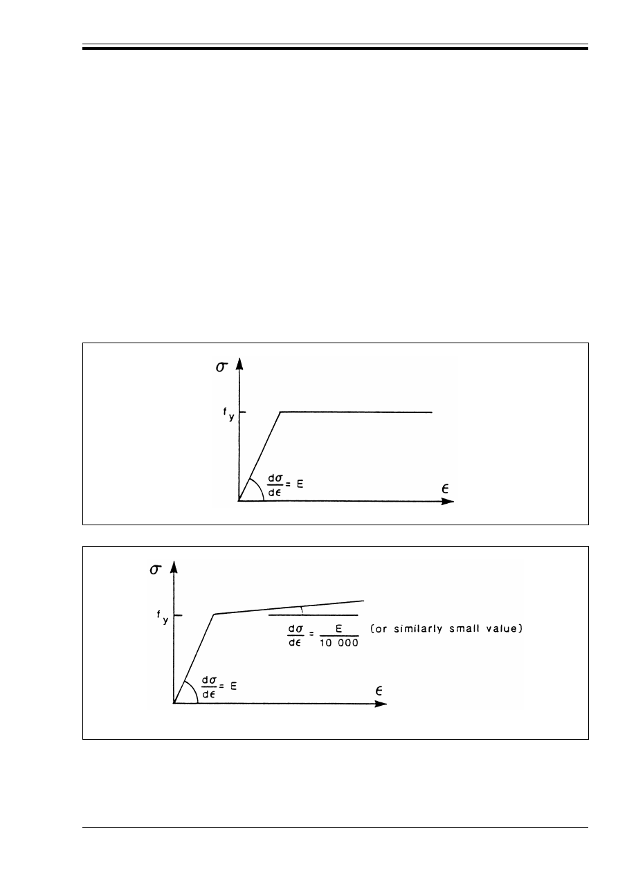
ENV 1993-1-1:1992
© BSI 04-2000
41
(7) In “Elastic — Perfectly Plastic” analysis, it is assumed that the cross-section remains fully elastic until
the plastic resistance moment is reached and then becomes fully plastic. Plastic deformations are assumed
to be concentrated at the plastic hinge locations.
(8) In “Elasto-plastic” analysis, the bi-linear stress-strain relationship indicated in Figure 5.2.1 may be used
for the grades of structural steel specified in Chapter 3. Alternatively, a more precise relationship may be
adopted. The cross-section remains fully elastic until the stress in the extreme fibres reaches the yield
strength. As the moment continues to increase, the section yields gradually as plasticity spreads across the
cross-section and plastic deformations extend partially along the member.
(9) To avoid possible computational difficulties when using a computer for elasto-plastic analysis, the
alternative bi-linear stress-strain relationship indicated in Figure 5.2.2 may be used if necessary.
(10) When elastic-plastic analysis is carried out, it may be assumed to be sufficient, in the case of building
structures, to apply the loads in a series of increments, stopping when the full design load is reached, and to
use the resulting internal forces and moments to check the resistances of the cross-sections and the buckling
resistances of the members.
(11) In the case of building structures, it is not normally necessary to consider the effects of alternating
plasticity.
Figure 5.2.1 — Bi-linear stress-strain relationship
Figure 5.2.2 — Alternative bi-linear stress-strain relationship (for use in elasto-plastic
analysis only)

ENV 1993-1-1:1992
42
© BSI 04-2000
5.2.2 Design assumptions
5.2.2.1 Basis
(1) The assumptions made in the global analysis of the structure shall be consistent with the anticipated
type of behaviour of the connections.
(2) The assumptions made in the design of the members shall be consistent with (or conservative in relation
to) the method used for the global analysis and with the anticipated type of behaviour of the connections.
(3) Table 5.2.1 shows the type of connections required for different types of framing, depending on the
method of global analysis used.
(4) The requirements for the various types of connections are given in 6.4.2 and 6.4.3
(5) For classification of beam-to-column connections as rigid or semi-rigid see 6.9.6.
(6) When it is necessary to calculate the elastic critical load for failure of a frame in a sway mode, account
should be taken of the effects of any semi-rigid connections, irrespective of whether elastic analysis or plastic
analysis is used for the global analysis of the frame.
(7) Where semi-rigid connections are used, the initial value of the rotational stiffness (see 6.9.6) should be
used when calculating elastic critical loads or buckling lengths.
5.2.2.2 Simple framing
(1) In simple framing the connections between the members may be assumed not to develop moments. In the
global analysis, members may be assumed to be effectively pin connected.
(2) The connections should satisfy the requirements for nominally pinned connections, either:
a) as given in 6.4.2.1.
b) as given in 6.4.3.1
5.2.2.3 Continuous framing
(1) Elastic analysis should be based on the assumption of full continuity, with rigid connections which
satisfy the requirements given in 6.4.2.2.
(2) Rigid-Plastic analysis should be based on the assumption of full continuity, with full strength
connections which satisfy the requirements given in 6.4.3.2.
(3) Elastic-Plastic analysis should be based on the assumption of full continuity with rigid full-strength
connections which satisfy the requirements given in both 6.4.2.2 and 6.4.3.2.
5.2.2.4 Semi-continuous framing
(1) Elastic analysis should be based on reliably predicted design moment-rotation or force-displacement
characteristics for the connections used.
(2) Rigid-Plastic analysis should be based on the design moment resistances of connections which have been
demonstrated to have sufficient rotation capacity, see 6.4.3 and 6.9.5.
(3) Elastic-Plastic analysis should be based on the design moment-rotation characteristics of the
connections, see 6.9.2.

ENV 1993-1-1:1992
© BSI 04-2000
43
Table 5.2.1 — Design assumptions
5.2.3 Structural systems
5.2.3.1 Structures
(1) The extent of global analysis required depends on the form of structure, as follows:
a) Simple structural elements:
Single-span beams and individual tension or compression members are statically determinate.
Triangulated frames may be statically determinate or statically indeterminate.
b) Continuous beams and non-sway frames:
Continuous beams and frames in which sway effects are negligible, or are eliminated by suitable means
(see 5.2.5), shall be analysed under appropriate arrangements of the variable loads to determine those
combinations of internal forces and moments which are critical for verifying the resistance of the
individual members and of the connections.
c) Sway frames:
Sway frames (see 5.2.5) shall be analysed under those arrangements of the variable loads which are
critical for failure in a sway mode. In addition, sway frames shall also be analysed for the non-sway
mode as described in b).
(2) The initial sway imperfections specified in 5.2.4.3 — and member imperfections where necessary,
see 5.2.4.2(4) — shall be included in the global analysis of all frames.
Type of framing
Method of global analysis
Types of connections
Simple
Pin joints
Nominally pinned (6.4.2.1)
Nominally pinned (6.4.3.1)
Continuous
Elastic
Rigid (6.4.2.2)
Nominally pinned (6.4.3.1)
Rigid-Plastic
Full-strength (6.4.3.2)
Nominally pinned (6.4.3.1)
Elastic-Plastic
Full-strength — Rigid
(6.4.3.2 and 6.4.2.2)
Nominally pinned
(6.4.3.1 and 6.4.2.1)
Semi-continuous
Elastic
Semi-rigid (6.4.2.3)
Rigid (6.4.2.2)
Nominally pinned (6.4.2.1)
Rigid-Plastic
Partial-strength (6.4.3.3)
Full-strength (6.4.3.2)
Nominally pinned (6.4.3.1)
Elastic-Plastic
Partial-strength — Semi-rigid
(6.4.3.3 and 6.4.2.3)
Partial-strength — Rigid
(6.4.3.3 and 6.4.2.2)
Full-strength — Semi-rigid
(6.4.3.2 and 6.4.2.3)
Full-strength — Rigid
(6.4.3.2 and 6.4.2.2)
Nominally pinned
(6.4.3.1 and 6.4.2.1)

ENV 1993-1-1:1992
44
© BSI 04-2000
5.2.3.2 Sub-frames
(1) For the global analysis, the structure may be sub-divided into a number of sub-frames, provided that:
• the structural interaction between the sub-frames is reliably modelled.
• the arrangement of the sub-frames is appropriate for the structural system used.
• account is taken of possible adverse effects of interaction between the sub-frames.
5.2.3.3 Stiffness of bases
(1) Account shall be taken of the deformation characteristics of the bases or other foundations to which
columns have moment-resisting connections. Appropriate rotational stiffness values shall be adopted in all
methods of global analysis other than the rigid-plastic method.
(2) Where an actual pin or rocker is used, the rotational stiffness of the foundation shall be taken as zero.
(3) Optionally, appropriate rotational stiffness values may also be adopted to represent the semi-rigid nature
of nominally pinned bases.
5.2.3.4 Simple framing
(1) Suitable methods of modelling structures with simple framing are given in Annex H
13)
.
5.2.3.5 Continuous framing
(1) Suitable sub-frames for global analysis of rigid-jointed frames are given in Annex H
13)
.
5.2.3.6 Semi-continuous framing
(1) Suitable sub-frames may also be used for the global analysis of structures with semi-continuous framing,
see Annex H
13)
.
5.2.4 Allowance for imperfections
5.2.4.1 Basis
(1) Appropriate allowances shall be incorporated to cover the effects of practical imperfections, including
residual stresses and geometrical imperfections such as lack of verticality, lack of straightness, lack of fit
and the unavoidable minor eccentricities present in practical connections.
(2) Suitable equivalent geometric imperfections may be used, with values which reflect the possible effects
of all types of imperfection.
(3) The effects of imperfections shall be taken into account in the following cases:
a) Global analysis
b) Analysis of bracing systems
c) Member design
5.2.4.2 Method of application
(1) Imperfections shall be allowed for in the analysis by including appropriate additional quantities,
comprising frame imperfections, member imperfections and imperfections for analysis of bracing systems.
(2) The effects of the frame imperfections given in 5.2.4.3 shall be included in the global analysis of the
structure. The resulting forces and moments shall be used for member design.
(3) The effects of the imperfections given in 5.2.4.4 shall be included in the analysis of bracing systems. The
resulting forces shall be used for member design.
(4) The effects of member imperfections (see 5.2.4.5) may be neglected when carrying out the global
analysis of frames, except in sway frames (see 5.2.5.2) in the case of members which are subject to axial
compression, which have moment-resisting connections and in which:
13)
To be prepared at a later stage.
(5.1)
where N
Sd
is
the design value of the compressive force
and
is
the in-plane non-dimensional slenderness (see 5.5.1.2) calculated using a buckling
length equal to the system length.
Æ

ENV 1993-1-1:1992
© BSI 04-2000
45
5.2.4.3 Frame imperfections
(1) The effects of imperfections shall be allowed for in frame analysis by means of an equivalent geometric
imperfection in the form of an initial sway imperfection Ì determined from:
(2) Columns which carry a vertical load N
Sd
of less than 50 % of the mean value of the vertical load per
column in the plane considered, shall not be included in n
c
.
(3) Columns which do not extend through all the storeys included in n
s
shall not be included in n
c
. Those
floor levels and roof levels which are not connected to all the columns included in n
c
shall not be included
when determining n
s
.
NOTE Where more than one combination of n
c
and n
s
satisfies these conditions, any such combination can safely be used.
(4) These initial sway imperfections apply in all horizontal directions, but need only be considered in one
direction at a time.
(5) The possible torsional effects on the structure of anti-symmetric sways, on two opposite faces, shall also
be considered.
(6) If more convenient, the initial sway imperfection may be replaced by a closed system of equivalent
horizontal forces, see Figure 5.2.3.
(7) In beam-and-column building frames, these equivalent horizontal forces should be applied at each floor
and roof level and should be proportionate to the vertical loads applied to the structure at that level,
see Figure 5.2.4.
(8) The horizontal reactions at each support should be determined using the initial sway imperfection and
not the equivalent horizontal forces. In the absence of actual horizontal loads, the net horizontal reaction is
zero.
5.2.4.4 Imperfections for analysis of bracing systems
(1) The effects of imperfections shall be allowed for in the analysis of bracing systems which are required
to provide lateral stability within the length of beams or compression members, by means of an equivalent
geometric imperfection of the members to be restrained, in the form of an initial bow imperfection:
in which n
r
is the number of members to be restrained.
(2) For convenience, the initial bow imperfections of the members to be restrained by a bracing system, may
be replaced by the equivalent stabilizing force shown in Figure 5.2.5.
(3) Where the bracing system is required to stabilize a beam, the force N in Figure 5.2.5 should be obtained
from:
(4) At points where beams or compression members are spliced, it shall also be verified that the bracing
system is able to resist a local force equal to k
r
N/100 applied to it by each beam or compression member
which is spliced at that point, and to transmit this force to the adjacent points at which that beam or
compression member is restrained, see Figure 5.2.6.
(5) When checking for this local force, any external loads acting on the bracing system shall also be
included, but the forces arising from the imperfection given in (1) may be omitted.
Ì = k
c
k
s
Ì
o
(5.2)
with
Ì
o
= 1/200
k
c
= [0,5 + 1/n
c
]
0,5
but k
c
k 1,0
and
k
s
= [0,2 + 1/n
s
]
0,5
but k
s
k 1,0
where n
c
is the number of columns per plane
and
n
s
is the number of storeys.
e
o
= k
r
L/500.
(5.3)
where L is the span of the bracing system
and
k
r
= [0,2 + 1/n
r
]
0,5
but k
r
k 1,0
N = M/h
(5.4)
where
M is the maximum moment in the beam
and
h is the overall depth of the beam.
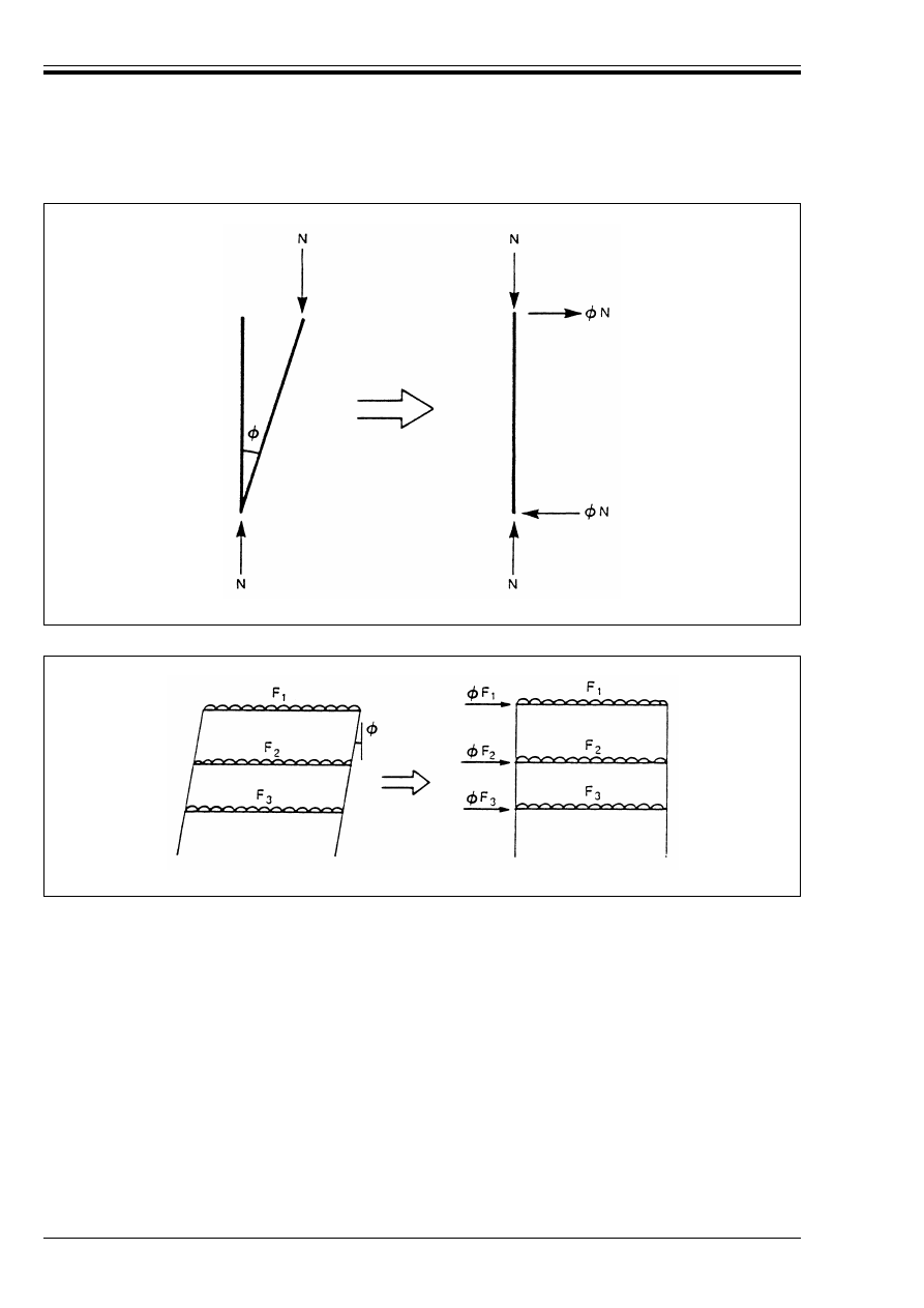
ENV 1993-1-1:1992
46
© BSI 04-2000
5.2.4.5 Member imperfections
(1) Normally the effects of imperfections on member design shall be incorporated by using the appropriate
buckling formulae given in this Eurocode.
(2) Alternatively, for a compression member, the initial bow imperfection specified in 5.5.1.3 may be
included in a second order analysis of the member.
(3) Where it is necessary (according to 5.2.4.2) to allow for member imperfections in the global analysis, the
imperfections specified in 5.5.1.3 shall be included and second order global analysis shall be used.
5.2.5 Sway stability
5.2.5.1 Sway stiffness
(1) All structures shall have sufficient stiffness to limit lateral sway. This may be supplied by:
a) the sway stiffness of bracing systems, which may be:
• triangulated frames
• rigid-jointed frames
• shear walls, cores and the like
Figure 5.2.3 — Replacement of initial sway imperfections by equivalent horizontal forces
Figure 5.2.4 — Equivalent horizontal forces
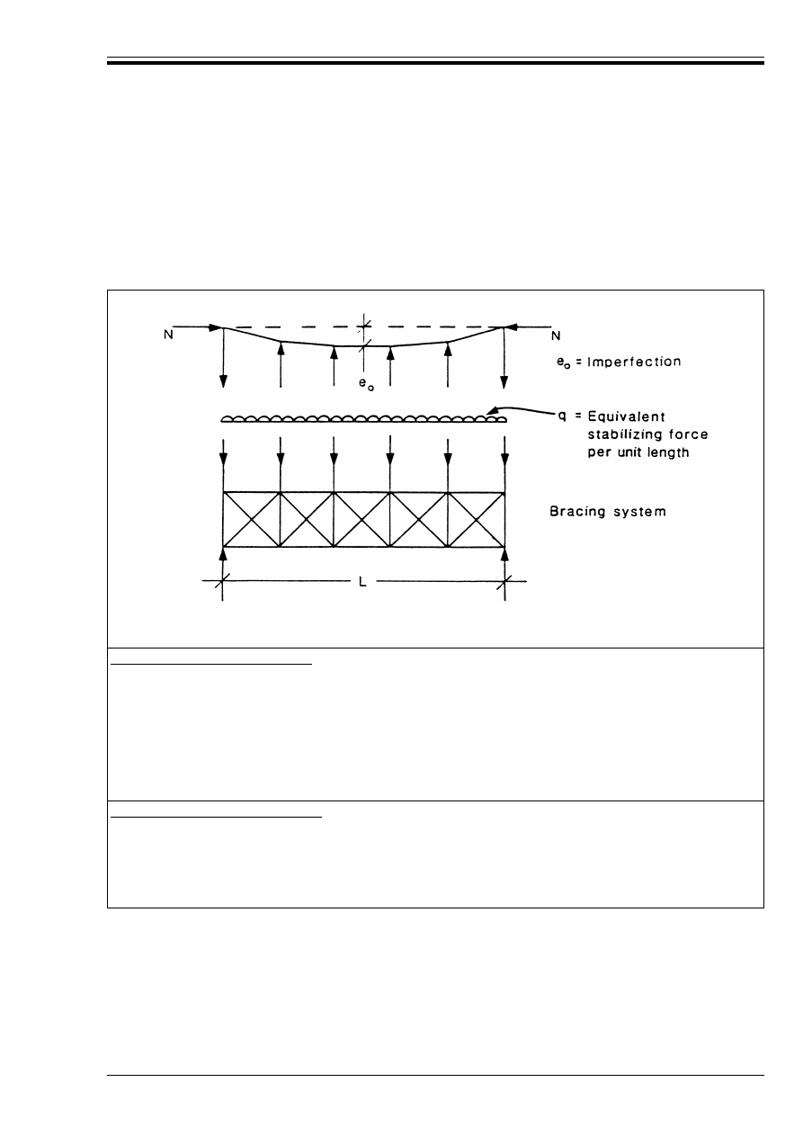
ENV 1993-1-1:1992
© BSI 04-2000
47
b) the sway stiffness of the frames, which may be supplied by one or more of the following:
• triangulation
• the stiffness of the connections
• cantilever columns
(2) Semi-rigid connections may be used, provided that they can be demonstrated to provide sufficient
reliable rotational stiffness (see 6.9.4) to satisfy the requirements for sway-mode frame stability, see 5.2.6.
The force N is assumed uniform within the span L of the bracing system. For non-uniform force
this is slightly conservative.
For a single restrained member:
for
¸
q
k
: q =
for
¸
q
>
: q =
where
¸
q
is the in-plane deflection of the bracing system due to q plus any external loads
and
µ
= 500 ¸
q
/L
but µ U 0,2
For multiple restrained members:
for
¸
q
k
: q =
for
¸
q
>
: q =
Figure 5.2.5 — Equivalent stabilizing force
L
2500
-------------
N
50L
----------
L
2500
-------------
N
60L
---------- 1 !
+
[
]
L
2500
-------------
CN
60L
---------- k
r
0,2
+
[
]
L
2500
-------------
CN
60L
---------- k
r
!
+
[
]
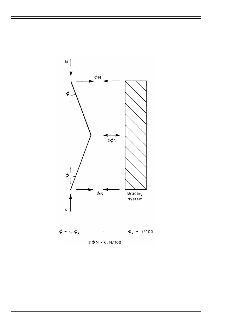
ENV 1993-1-1:1992
48
© BSI 04-2000
5.2.5.2 Classification as sway or non-sway
(1) A frame may be classified as non-sway if its response to in-plane horizontal forces is sufficiently stiff for
it to be acceptably accurate to neglect any additional internal forces or moments arising from horizontal
displacements of its nodes.
(2) Any other frame shall be classified as a sway frame and the effects of the horizontal displacements of
its nodes taken into account in its design, see 5.2.1.2.
Figure 5.2.6 — Bracing forces at splices in compression elements
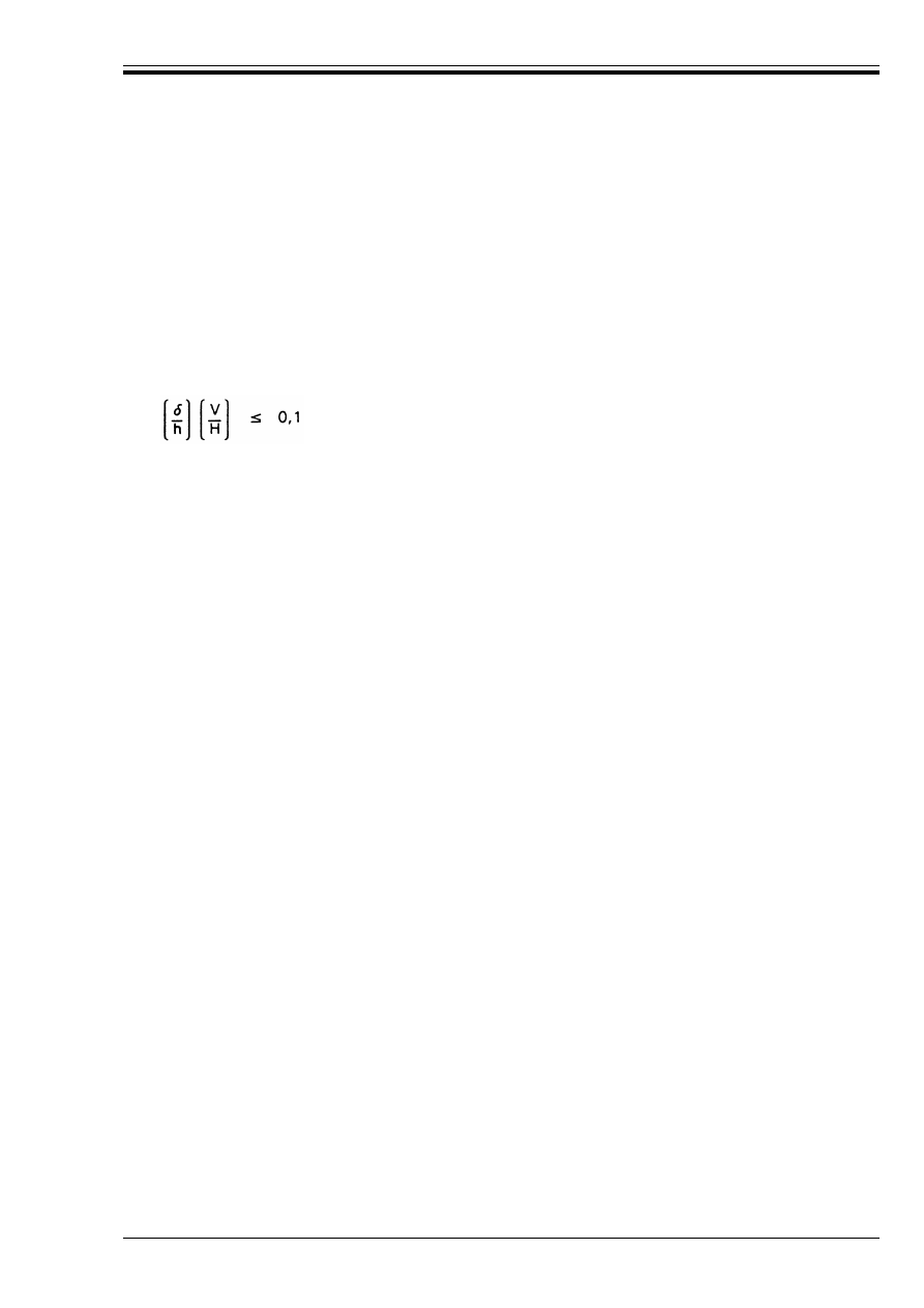
ENV 1993-1-1:1992
© BSI 04-2000
49
(3) A frame may be classified as non-sway for a given load case if the elastic critical load ratio V
Sd
/V
cr
for
that load case satisfies the criterion:
(4) Beam-and-column type plane frames in building structures with beams connecting each column at each
storey level (see Figure 5.2.7) may be classified as non-sway for a given load case if the following criterion is
satisfied. When first order theory is used, the horizontal displacements in each storey due to the design loads
(both horizontal and vertical), plus the initial sway imperfection (see 5.2.4.3) applied in the form of
equivalent horizontal forces, should satisfy the criterion:
(5) For sway frames, the requirements for frame stability given in 5.2.6 should also be satisfied.
5.2.5.3 Classification as braced or unbraced
(1) A frame may be classified as braced if its sway resistance is supplied by a bracing system with a
response to in-plane horizontal loads which is sufficiently stiff for it to be acceptably accurate to assume
that all horizontal loads are resisted by the bracing system.
(2) A steel frame may be classified as braced if the bracing system reduces its horizontal displacements by
at least 80 %.
(3) A braced frame may be treated as fully supported laterally.
(4) The effects of the initial sway imperfections (see 5.2.4.3) in the braced frame shall be taken into account
in the design of the bracing system.
(5) The initial sway imperfections (or the equivalent horizontal forces, see 5.2.4.3) plus any horizontal loads
applied to a braced frame, may be treated as affecting only the bracing system.
(6) The bracing system should be designed to resist:
• any horizontal loads applied to the frames which it braces,
• any horizontal or vertical loads applied directly to the bracing system,
• the effects of the initial sway imperfections (or the equivalent horizontal forces) from the bracing
system itself and from all the frames which it braces.
(7) Where the bracing system is a frame or sub-frame, it may itself be either sway or non-sway, see 5.2.5.2.
(8) When applying the criterion given in 5.2.5.2(3) to a frame or sub-frame acting as a bracing system, the
total vertical load acting on all the frames which it braces should also be included.
(9) When applying the criterion given in 5.2.5.2(4) to a frame or sub-frame acting as a bracing system, the
total horizontal and vertical load acting on all the frames which it braces should also be included, plus the
initial sway imperfection applied in the form of the equivalent horizontal forces from the bracing system
itself and from all the frames which it braces.
V
Sd
/V
cr
k0,1
(5.5)
where
V
Sd
is the design value of the total vertical load
and
V
cr
is its elastic critical value for failure in a sway mode.
(5.6)
where
¸
is the horizontal displacement at the top of the storey, relative to the bottom of the storey
h
is the storey height
H
is the total horizontal reaction at the bottom of the storey
and
V
is the total vertical reaction at the bottom of the storey.
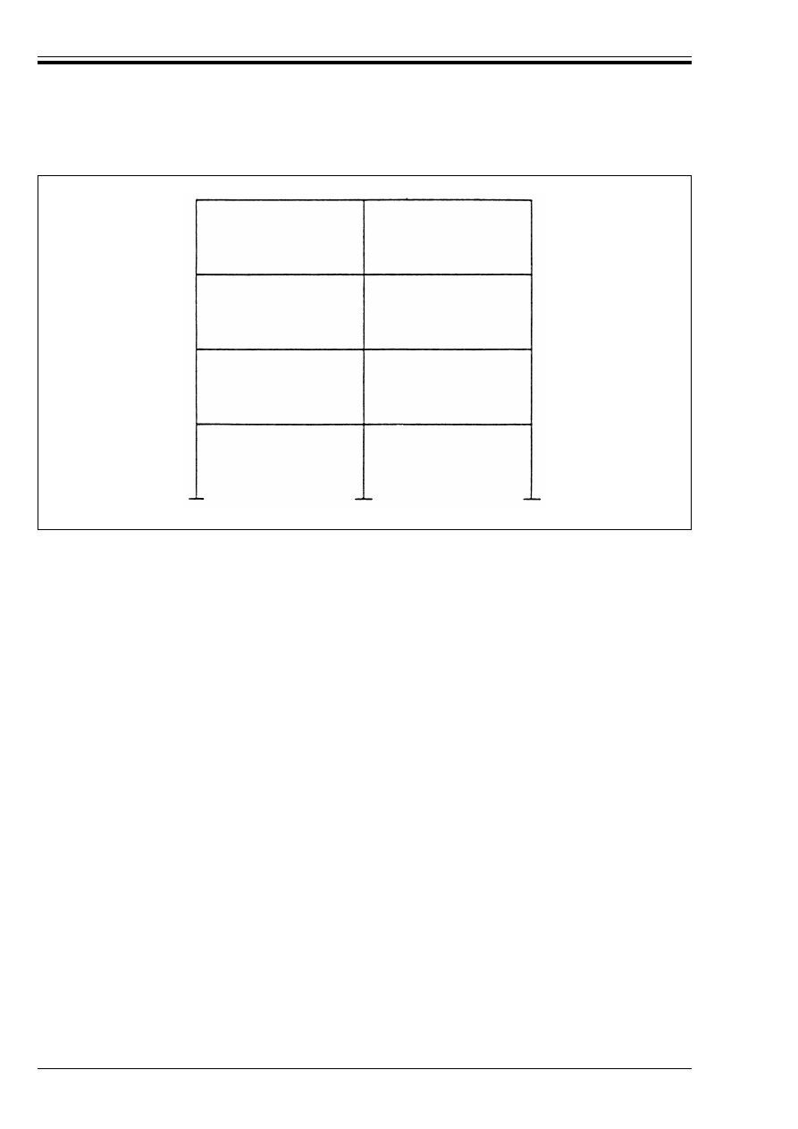
ENV 1993-1-1:1992
50
© BSI 04-2000
5.2.6 Frame stability
5.2.6.1 General
(1) All frames shall have adequate resistance to failure in a sway mode. However, where the frame is shown
to be a non-sway frame, see 5.2.5.2, no further sway mode verification is required.
(2) All frames, including sway frames, shall also be checked for adequate resistance to failure in non-sway
modes.
(3) A check should be included for the possibility of local storey-height failure modes.
(4) Frames with non-triangulated pitched roofs shall also be checked for snap-through buckling.
(5) The use of rigid-plastic analysis with plastic hinge locations in the columns shall be limited to cases
where it can be demonstrated that the columns are able to form hinges with sufficient rotation capacity,
see 5.2.7.
5.2.6.2 Elastic analysis of sway frames
(1) When elastic global analysis is used, the second order effects in the sway mode shall be included, either
directly by using second order elastic analysis, or indirectly by using one of the following alternatives:
a) first order elastic analysis, with amplified sway moments.
b) first order elastic analysis, with sway-mode buckling lengths.
(2) When second order elastic global analysis is used, in-plane buckling lengths for the non-sway mode may
be used for member design.
(3) In the amplified sway moments method, the sway moments found by a first order elastic analysis should
be increased by multiplying them by the ratio:
(4) The amplified sway moments method should not be used when the elastic critical load ratio V
Sd
/V
cr
is
more than 0,25.
Figure 5.2.7 — Building frame with beams connecting each column at each storey level
(5.7)
where
V
Sd
is the design value of the total vertical load
and
V
cr
is its elastic critical value for failure in a sway mode.
1
1 V
Sd
/
V
cr
–
-------------------------------

ENV 1993-1-1:1992
© BSI 04-2000
51
(5) Sway moments are those associated with the horizontal translation of the top of a storey relative to the
bottom of that storey. They arise from horizontal loading and may also arise from vertical loading if either
the structure or the loading is asymmetrical.
(6) As an alternative to determining V
Sd
/V
cr
direct the following approximation may be used in
beam-and-column type frames as described in 5.2.5.2(4):
where ¸, h, H and V are as defined 5.2.5.2(4).
(7) When the amplified sway moments method is used, in-plane buckling lengths for the non-sway mode may
be used for member design.
(8) When first order elastic analysis, with sway-mode in-plane buckling lengths, is used for column design,
the sway moments in the beams and the beam-to-column connections should be amplified by at least 1,2
unless a smaller value is shown to be adequate by analysis.
5.2.6.3 Plastic analysis of sway frames
(1) When plastic global analysis is used, allowance shall be made for the second order effects in the sway
mode.
(2) This should generally be done by using second order elastic-plastic analysis, see 5.2.1.4.
(3) However, as an alternative, rigid-plastic analysis with indirect allowance for second-order effects, as
given in (4) below, may be adopted in the following cases:
a) Frames one or two storeys high in which either:
• no plastic hinge locations occur in the columns, or
• the columns satisfy 5.2.7.
b) Frames with fixed bases, in which the sway failure mode involves plastic hinge locations in the columns
at the fixed bases only, see Figure 5.2.8, and the design is based on an incomplete mechanism in which
the columns are designed to remain elastic at the calculated plastic hinge moment.
(4) In the cases given in (3), V
Sd
/V
cr
should not exceed 0,20 and all the internal forces and moments should
be amplified by the ratio given in 5.2.6.2(3).
(5) In-plane buckling lengths for the non-sway mode may be used for member design. These should be
determined with due allowance for the effects of plastic hinges.
5.2.7 Column requirements for plastic analysis
(1) In frames it is necessary to ensure that where plastic hinges are required to form in members which are
also under compression, adequate rotation capacity is available.
(2) This criterion may be assumed to be satisfied when elastic-plastic global analysis is used, provided that
the cross-sections satisfy the requirements given in 5.3.3.
(3) When plastic hinge locations occur in the columns of frames designed using first order rigid-plastic
analysis, the columns should satisfy the following:
(4) where is the in-plane non-dimensional slenderness (see 5.5.1.2) calculated using a buckling length
equal to the system length.
(5) In frames designed using first order rigid-plastic global analysis, columns containing plastic hinge
locations should also be checked for resistance to in-plane buckling, using buckling lengths equal to their
system lengths.
(6) Except for the method outlined in 5.2.6.3(3) b), first order rigid-plastic global analysis should not be used
for unbraced frames with more than two storeys.
(5.8)
w
in braced frames:
(5.9)
w
in unbraced frames:
(5.10)
Æ
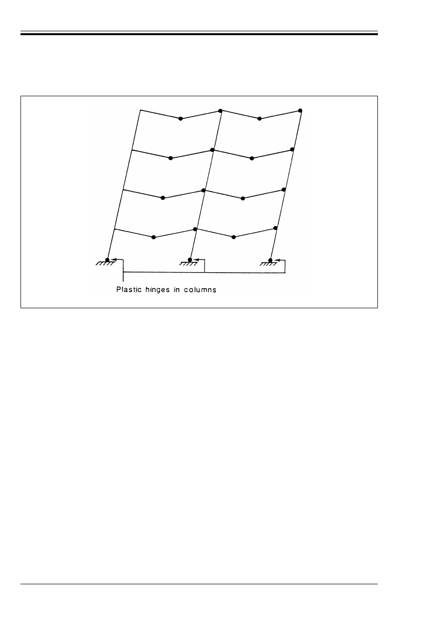
ENV 1993-1-1:1992
52
© BSI 04-2000
5.3 Classification of cross-sections
5.3.1 Basis
(1) When plastic global analysis is used, the members shall be capable of forming plastic hinges with
sufficient rotation capacity to enable the required redistribution of bending moments to develop.
(2) When elastic global analysis is used, any class of cross-section may be used for the members, provided
that the design of the members takes into account the possible limits on the resistance of cross-sections due
to local buckling.
5.3.2 Classification
(1) Four classes of cross-sections are defined, as follows:
• Class 1 cross-sections are those which can form a plastic hinge with the rotation capacity required for
plastic analysis.
• Class 2 cross-sections are those which can develop their plastic moment resistance, but have limited
rotation capacity.
• Class 3 cross-sections are those in which the calculated stress in the extreme compression fibre of the
steel member can reach its yield strength, but local buckling is liable to prevent development of the
plastic moment resistance.
• Class 4 cross-sections are those in which it is necessary to make explicit allowances for the effects of
local buckling when determining their moment resistance or compression resistance.
(2) Effective widths may be used in Class 4 cross-sections to make the necessary allowances for reductions
in resistance due to the effects of local buckling, see 5.3.5.
(3) The classification of a cross-section depends on the proportions of each of its compression elements.
(4) Compression elements include every element of a cross-section which is either totally or partially in
compression, due to axial force or bending moment, under the load combination considered.
(5) The various compression elements in a cross-section (such as a web or a flange) can, in general, be in
different classes.
Figure 5.2.8 — Sway mechanism involving plastic hinges in columns at bases only

ENV 1993-1-1:1992
© BSI 04-2000
53
(6) A cross-section is normally classified by quoting the highest (least favourable) class of its compression
elements.
(7) Alternatively the classification of a cross-section may be defined by quoting both the flange classification
and the web classification.
(8) The limiting proportions for Class 1, 2, and 3 compression elements should be obtained from
Table 5.3.1. An element which fails to satisfy the limits for Class 3 should be taken as Class 4.
5.3.3 Cross-section requirements for plastic global analysis
(1) At plastic hinge locations, the cross-section of the member which contains the plastic hinge shall have
an axis of symmetry in the plane of loading.
(2) At plastic hinge locations, the cross-section of the member which contains the plastic hinge shall have
a rotation capacity of not less than the required rotation at that plastic hinge location.
(3) To satisfy the above requirement, the required rotations should be determined from a rotation analysis.
(4) For building structures in which the required rotations are not calculated, all members containing
plastic hinges shall have Class 1 cross-sections at the plastic hinge location.
(5) Where the cross-sections of the members vary along their length, the following additional criteria should
be satisfied:
a) Adjacent to plastic hinge locations, the thickness of the web should not be reduced for a distance along
the beam from the plastic hinge location of at least 2d, where d is the clear depth of the web at the plastic
hinge location.
b) Adjacent to plastic hinge locations, the compression flange should be Class 1 for a distance along the
beam from the plastic hinge location of not less than the greater of:
• 2d, where d is as defined in a)
• the distance to the point at which the moment in the beam has fallen to 0,8 times the plastic moment
resistance at the point concerned.
c) Elsewhere the compression flange should be Class 1 or Class 2 and the web should be Class 1, Class 2
or Class 3.
5.3.4 Cross-section requirements when elastic global analysis is used
(1) When elastic global analysis is used, the role of cross-section classification is to identify the extent to
which the resistance of a cross-section is limited by its local buckling resistance.
(2) When all the compression elements of a cross-section are Class 2, the cross-section may be taken as
capable of developing its full plastic resistance moment.
(3) When all the compression elements of a cross-section are Class 3, its resistance may be based on an
elastic distribution of stresses across the cross-section, limited to the yield strength at the extreme fibres.
(4) When yielding first occurs on the tension side of the neutral axis, the plastic reserves of the tension zone
may be utilised when determining the resistance of a Class 3 cross-section, using the method given in
ENV 1993-1-3 Eurocode 3-1.3
14)
.
(5) The resistance of a cross-section with a Class 2 compression flange but a Class 3 web may alternatively
be determined by treating the web as an effective Class 2 web with a reduced effective area, using the method
given in ENV 1994-1-1 Eurocode 4-1.1
14)
.
(6) When any of the compression elements of a cross-section is Class 4 the cross-section shall be designed
as a Class 4 cross-section, see 5.3.5.
14)
In preparation.
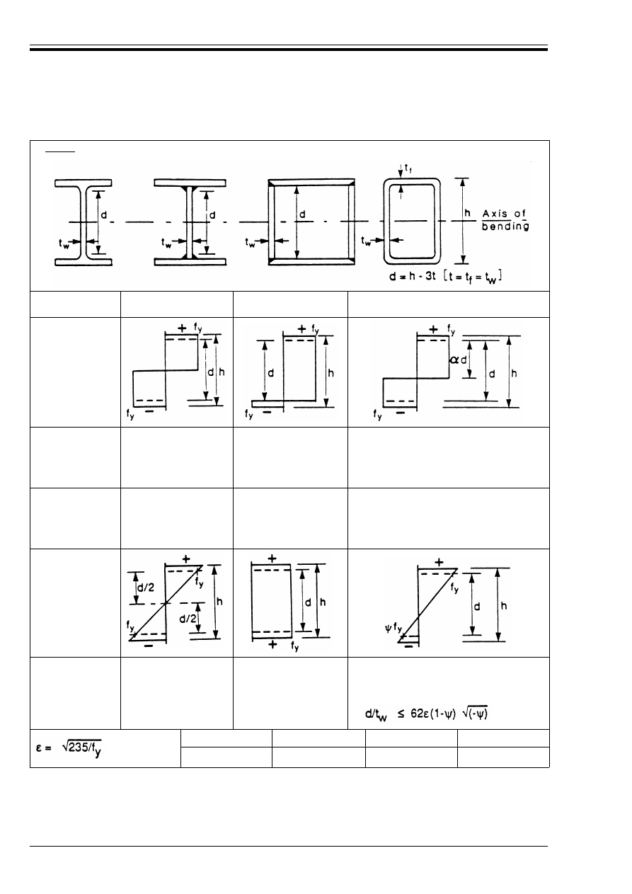
ENV 1993-1-1:1992
54
© BSI 04-2000
Table 5.3.1 — Maximum width-to-thickness ratios for compression elements (Sheet 1)
a) Webs: (internal elements perpendicular to axis of bending)
Class
Web subject to bending
Web subject to
compression
Web subject to bending and compression
Stress
distribution in
element
(compression
positive)
1
d/t
W
k 72¼
d/t
W
k 33¼
when ! > 0,5:
d/t
W
k 396¼/(13! – 1)
when ! k0,5:
d/t
W
k 36¼/!
2
d/t
W
k 83¼
d/t
W
k 38¼
when ! > 0,5:
d/t
W
k 456¼/(13! – 1)
when µ k 0,5:
d/t
W
k 41,5¼/!
Stress
distribution in
element
(compression
positive)
3
d/t
W
k 124¼
d/t
W
k 42¼
when > > – 1:
d/t
W
k 42¼/(0,67 + 0,33>)
when > k – 1:
f
y
235
275
355
¼
1
0,92
0,81
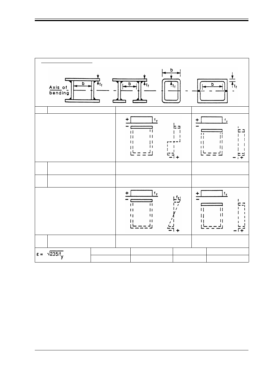
ENV 1993-1-1:1992
© BSI 04-2000
55
Table 5.3.1 — Maximum width-to-thickness ratios for compression elements (Sheet 2)
b) Internal flange elements: (internal elements parallel to axis of bending)
Class
Type
Section in bending
Section in compression
Stress distribution in
element and across section
(compression positive)
1
Rolled Hollow Section
Other
(b-3t
f
)/t
f
b/t
f
k 33¼
k 33¼
(b-3t
f
)/t
f
b/t
f
k 42¼
k 42¼
2
Rolled Hollow Section
Other
(b-3t
f
)/t
f
b/t
f
k 38¼
k 38¼
(b-3t
f
)/t
f
b/t
f
k 42¼
k 42¼
Stress distribution in
element and across section
(compression positive)
3
Rolled Hollow Section
Other
(b-3t
f
)/t
f
b/t
f
k 42¼
k 42¼
(b-3t
f
)/t
f
b/t
f
k 42¼
k 42¼
f
Y
235
275
355
¼
1
0,92
0,81
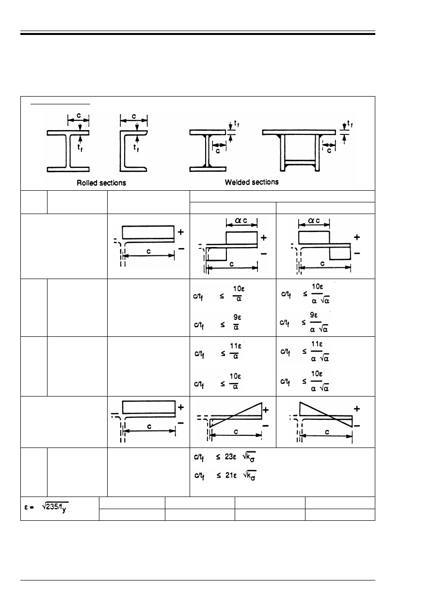
ENV 1993-1-1:1992
56
© BSI 04-2000
Table 5.3.1 — Maximum width-to-thickness ratios for compression elements (Sheet 3)
c) Outstand flanges:
Class
Type of section
Flange subject to
compression
Flange subject to compression and bending
Tip in compression
Tip in tension
Stress distribution
in element
(compression positive)
1
Rolled
c/t
f
k 10¼
Welded
c/t
f
f
k 9¼
2
Rolled
c/t
f
k 11¼
Welded
c/t
f
k 10¼
Stress distribution
in element
(compression positive)
3
Rolled
c/t
f
k 15¼
Welded
c/t
f
k 14¼
For k
Ö
see Table 5.3.3
f
y
235
275
355
¼
1
0,92
0,81
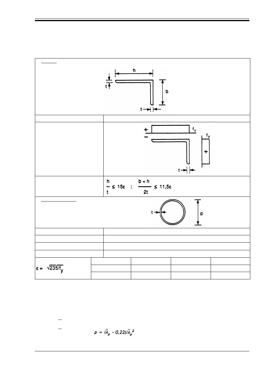
ENV 1993-1-1:1992
© BSI 04-2000
57
Table 5.3.1 — Maximum width-to-thickness ratios for compression elements (Sheet 4)
5.3.5 Effective cross-section properties of Class 4 cross-sections
(1) The effective cross-section properties of Class 4 cross-sections shall be based on the effective widths of
the compression elements [see 5.3.2(2)].
(2) The effective widths of flat compression elements should be obtained using Table 5.3.2 for internal
elements and Table 5.3.3 for outstand elements.
(3) As an approximation, the reduction factor Ô may be obtained as follows:
d) Angles:
Refer also to c)
“Outstand flanges”
(see Sheet 3).
(Does not apply to
angles in continuous
contact with other
components)
Class
Section in compression
Stress distribution
across section
(compression positive)
3
e) Tubular sections:
Class
Section in bending and/or compression
1
d/t k 50¼
2
2
d/t k 70¼
2
3
d/t k 90¼
2
f
y
235
275
355
¼
1
0,92
0,81
¼
2
1
0,85
0,66
w
when k 0,673:
Ô = 1
w
when > 0,673:
(5.11)
Æ
p
Æ
p
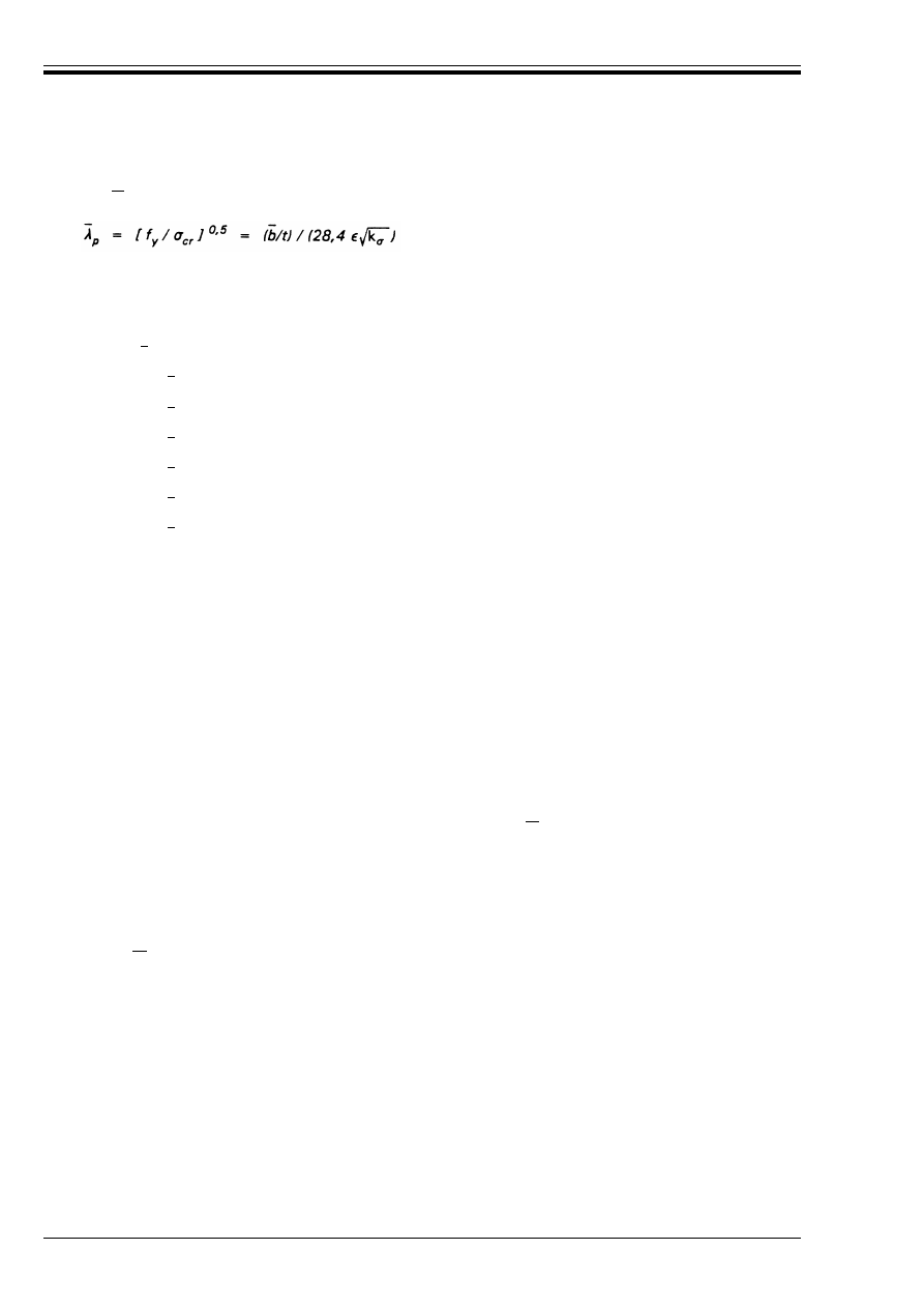
ENV 1993-1-1:1992
58
© BSI 04-2000
(4) To determine the effective widths of flange elements, the stress ratio Ò used in Table 5.3.2 or Table 5.3.3
may be based on the properties of the gross cross-section.
(5) To determine the effective width of a web, the stress ratio Ò used in Table 5.3.2 may be obtained using the
effective area of the compression flange but the gross area of the web.
(6) Generally the centroidal axis of the effective cross-section will shift by a dimension e compared to the
centroidal axis of the gross cross-section, see Figure 5.3.1 and Figure 5.3.2. This should be taken into account
when calculating the properties of the effective cross-section.
(7) When the cross-section is subject to an axial force, the method given in 5.4.8.3 should be used to take
account of the additional moment %M given by:
(8) Except as given in (9), for greater economy the plate slenderness
of an element may be determined
using the maximum calculated compressive stress Ö
com.Ed
in that element in place of the yield strength f
y
,
provided that Ö
com.Ed
is determined using the effective widths b
eff
of all the compression elements. This
procedure generally requires an iterative calculation in which Ò is determined again at each step from the
stresses calculated on the effective cross-section defined at the end of the previous step, including the stresses
from the additional moment %M.
(9) However, when verifying the design buckling resistance of a member using section 5.5, the plate
slenderness of an element should always be based on its yield strength f
y
when calculating the values of
A
eff
, e
N
and W
eff
.
where is the plate slenderness given by:
in which t
is the relevant thickness
Ö
cr
is the critical plate-buckling stress
k
Ö
is the buckling factor corresponding to the stress ratio Ò from Table 5.3.2 or
Table 5.3.3 as appropriate
and
is the appropriate width (see Table 5.3.1) as follows:
= d for webs
= b for internal flange elements (except RHS)
= b – 3t for flanges of RHS
= c for outstand flanges
= (b + h)/2 for equal-leg angles
= h or (b + h)/2 for unequal-leg angles
%M = N e
N
(5.12)
where e
N
is the shift of the centroidal axis when the effective cross-section is subject to uniform
compression, see Figure 5.3.1.
and N is positive for compression.
Æ
p
b
b
b
b
b
b
b
Æ
p
Æ
p
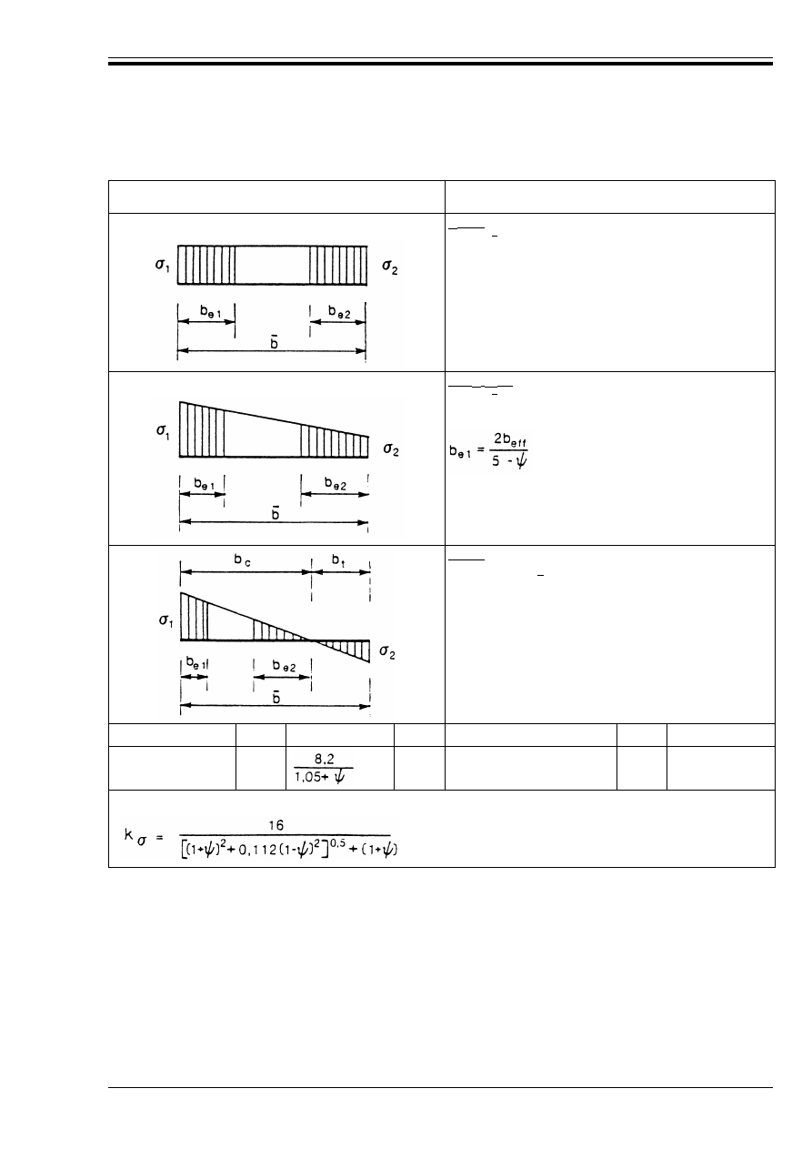
ENV 1993-1-1:1992
© BSI 04-2000
59
Table 5.3.2 — Internal compression elements
Stress distribution
(compression positive)
Effective width b
eff
Ò = 1:
b
eff
= Ô
b
e1
= 0.5b
eff
b
e2
= 0,5b
eff
1 > Ò U 0:
b
eff
= Ô
b
e2
= b
eff
– b
e1
Ò < 0:
b
eff
= Ô b
c
= @ /(1 – Ò)
b
e1
= 0,4b
eff
b
e2
= 0,6b
eff
Ò = Ö
2
/Ö
1
1
1 > Ò > 0
0
0 > Ò > – 1
– 1
– 1 > Ò > – 2
Buckling factor k
Ö
4,0
7,81
7,81 – 6,29 Ò + 9,78 Ò
2
23,9
5,98(1 – Ò)
2
Alternatively, for 1 U Ò U – 1:
b
b
b
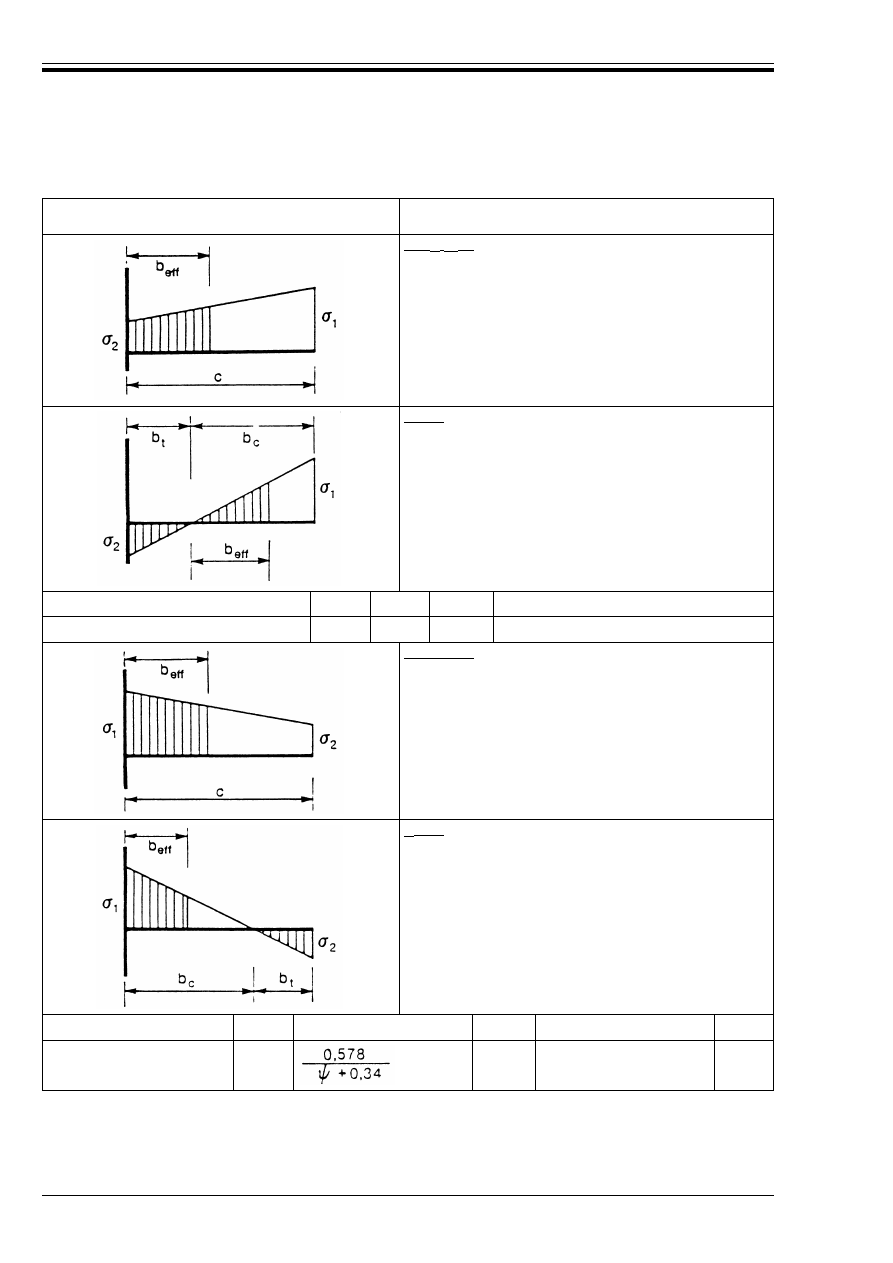
ENV 1993-1-1:1992
60
© BSI 04-2000
Table 5.3.3 — Outstand compression elements
Stress distribution
(compression positive)
Effective width b
eff
1 > Ò U 0:
b
eff
= Ôc
Ò < 0:
b
eff
= Ôb
c
= Ôc/(1 – Ò)
Ò = Ö
2
/Ö
1
1
0
– 1
1 UÒU– 1
Buckling factor k
Ö
0,43
0,57
0,85
0,57 – 0,21 Ò + 0,07 Ò
2
1 > Ò U 0:
b
eff
= Ôc
Ò < 0:
b
eff
= Ôb
c
= Ôc/(1 – Ò)
Ò = Ö
2
/Ö
1
1
1 > Ò > 0
0
0 > Ò > – 1
– 1
Buckling factor k
Ö
0,43
1,70
1,7 – 5 Ò + 17,1 Ò
2
23,8
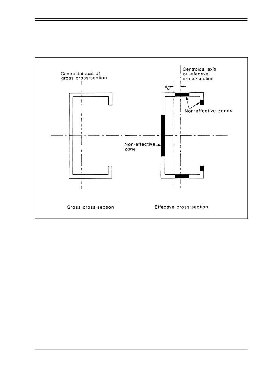
ENV 1993-1-1:1992
© BSI 04-2000
61
Figure 5.3.1 — Class 4 cross-sections — axial force
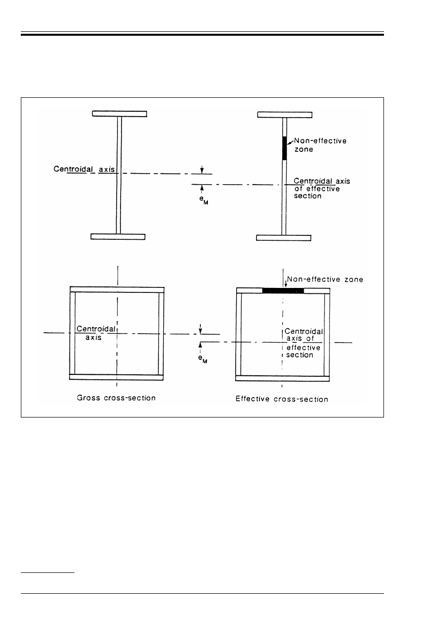
ENV 1993-1-1:1992
62
© BSI 04-2000
5.3.6 Effects of transverse forces on webs
(1) The effects of significant transverse compressive stresses on the local buckling resistance of a web shall
be taken into account in design. Such stresses may arise from transverse forces on a member and at
member intersections.
(2) The presence of significant transverse compressive stresses may effectively reduce the maximum values
of the depth-to-thickness ratios d/t
w
for Class 1, Class 2 and Class 3 webs below those given in
Table 5.3.1, depending on the spacing of any web stiffeners.
(3) A recognised method of verification should be used. Reference may be made to the application rules for
stiffened plating given in ENV 1993-2 Eurocode 3-2
15)
.
5.4 Resistance of cross-sections
5.4.1 General
(1) This clause covers the resistance of member cross-sections, which may be limited by:
• the plastic resistance of the gross cross-section
Figure 5.3.2 — Class 4 cross-sections — bending moment
15)
In preparation.

ENV 1993-1-1:1992
© BSI 04-2000
63
• the resistance of the net section at holes for fasteners
• shear lag effects
• local buckling resistance
• shear buckling resistance.
(2) The plastic resistance of a cross-section may be verified by finding a stress distribution which equilibrates
the internal forces and moments without exceeding the yield strength, provided that this stress distribution
is feasible, considering the associated plastic deformations.
(3) In addition to the requirements given in this clause, the buckling resistance of the member shall also
be verified, see 5.5.
(4) Where appropriate, frame stability should also be verified, see 5.2.1.2 and 5.2.6.
5.4.2 Section properties
5.4.2.1 Gross cross-section
(1) The properties of the gross cross-section shall be determined using the specified dimensions. Holes for
fasteners need not be deducted, but allowance shall be made for larger openings. Splice materials and
battens shall not be included.
5.4.2.2 Net area
(1) The net area of a member or element cross-section shall be taken as its gross area less appropriate
deductions for all holes and other openings.
(2) When calculating net section properties, the deduction for a single fastener hole shall be the gross cross-
sectional area of the hole in the plane of its axis. For countersunk holes, appropriate allowance shall be
made for the countersunk portion.
(3) Provided that the fastener holes are not staggered, the total area to be deducted for fastener holes shall
be the maximum sum of the sectional areas of the holes in any cross-section perpendicular to the member
axis.
(4) When the fastener holes are staggered, the total area to be deducted for fastener holes shall be the
greater of:
a) the deduction for non-staggered holes given in (3)
b) the sum of the sectional areas of all holes in any diagonal or zig-zag line extending progressively across
the member or part of the member, less s
2
t/(4p) for each gauge space in the chain of
holes, see Figure 5.4.1
where s is the staggered pitch, the spacing of the centres of two consecutive holes in the chain
measured parallel to the member axis.
p is the spacing of the centres of the same two holes measured perpendicular to the member
axis.
and
t is the thickness.
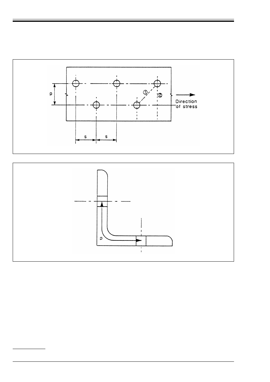
ENV 1993-1-1:1992
64
© BSI 04-2000
(5) In an angle or other member with holes in more than one plane, the spacing p shall be measured along
the centre of thickness of the material, see Figure 5.4.2.
5.4.2.3 Shear lag effects
(1) Shear lag effects in flanges may be neglected provided that:
(2) When these limits are exceeded an effective breadth of flange should be taken.
(3) The calculation of effective breadths of flanges is covered in ENV 1993-1-3 Eurocode 3-1.3
16)
and
ENV 1993-2 Eurocode 3-2
16)
.
Figure 5.4.1 — Staggered holes
Figure 5.4.2 — Angles with holes in both legs
w
for outstand elements:
c k L
o
/20
w
for internal elements:
b k L
o
/10
where L
o
is the length between points of zero moment.
b is the breadth
and
c
is the outstand
16)
In preparation.

ENV 1993-1-1:1992
© BSI 04-2000
65
5.4.3 Tension
(1) For members in axial tension, the design value of the tensile force N
sd
at each cross-section shall
satisfy:
where N
t.Rd
is the design tension resistance of the cross-section, taken as the smaller of:
a) the design plastic resistance of the gross cross-section
b) the design ultimate resistance of the net cross-section at holes for fasteners
(2) In Category C connections designed to be slip-resistant at the ultimate limit state (see 6.5.3.1), the
design plastic resistance of the net section at holes for fasteners N
net.Rd
shall not be taken as more than:
(3) For angles connected through one leg, see also 6.5.2.3 and 6.6.10. Similar consideration should also be
given to other types of sections connected through outstands such as T-sections and channels.
(4) Where ductile behaviour is required, the design plastic resistance N
p
=
.Rd
shall be less than the design
ultimate resistance of the net section at fastener holes N
u.Rd
, that is:
5.4.4 Compression
(1) For members in axial compression, the design value of the compressive force N
Sd
at each cross-section
shall satisfy:
where N
c.Rd
is the design compression resistance of the cross-section, taken as the smaller of:
a) the design plastic resistance of the gross section
N
pl.Rd
= Af
y
/¾
M0
b) the design local buckling resistance of the gross section
N
o.Rd
= A
eff
f
y
/¾
M1
where A
eff
is the effective area of the cross-section, see 5.3.5.
(2) The design compression resistance of the cross-section N
c.Rd
may be determined as follows:
(3) In the case of unsymmetrical Class 4 sections, the method given in 5.4.8.3 should be used to allow for the
additional moment %M due to the eccentricity of the centroidal axis of the effective section, see 5.3.5(7).
(4) In addition, the buckling resistance of the member shall also be verified, see 5.5.1.
(5) Fastener holes need not be allowed for in compression members, except for oversize and slotted holes.
5.4.5 Bending moment
5.4.5.1 Basis
(1) In the absence of shear force, the design value of the bending moment M
Sd
at each cross-section shall
satisfy:
where M
c.Rd
is the design moment resistance of the cross-section, taken as the smallest of:
a) the design plastic resistance moment of the gross section
M
p
=
.Rd
= W
p
=
f
y
/¾
M0
N
Sd
k N
t.Rd
(5.13)
N
p
=
.Rd
= Af
y
/¾
M0
N
u.Rd
= 0,9 A
net
f
u
/¾
M2
N
net.Rd
= A
net
f
y
/¾
M0
(5.14)
N
u.Rd
U N
p
=
.Rd
(5.15)
This will be satisfied if:
0,9[A
net
/A] U [f
y
/f
u
] [¾
M2
/¾
M0
]
N
Sd
k N
c.Rd
(5.16)
Class 1, 2 or 3 cross-sections:
N
c.Rd
= Af
y
/¾
M0
Class 4 cross-sections:
N
c.Rd
= A
eff
f
y
/¾
M1
M
Sd
k M
c.Rd
(5.17)

ENV 1993-1-1:1992
66
© BSI 04-2000
b) the design local buckling resistance moment of the gross section
M
o.Rd
= W
eff
f
y
/¾
M1
where W
eff
is the effective section modulus (see 5.3.5).
c) the design ultimate resistance moment of the net section at bolt holes M
u.Rd
, see 5.4.5.3.
(2) For a Class 3 cross-section the design moment resistance of the gross section shall be taken as the design
elastic resistance moment given by:
(3) Refer to 5.4.7 for combinations of bending moment and shear force.
(4) In addition, the resistance of the member to lateral-torsional buckling shall also be verified, see 5.5.2.
5.4.5.2 Bending about one axis
1) In the absence of shear force, the design moment resistance of a cross-section without holes for
fasteners may be determined as follows:
5.4.5.3 Holes for fasteners
(1) Fastener holes in the tension flange need not be allowed for, provided that for the tension flange:
(2) When A
f.net
/A
f
is less than this limit, a reduced flange area may be assumed which satisfies the limit.
(3) Fastener holes in the tension zone of the web need not be allowed for, provided that the limit given in (1)
is satisfied for the complete tension zone comprising the tension flange plus the tension zone of the web.
(4) Fastener holes in the compression zone of the cross-section need not be allowed for, except for oversize
and slotted holes.
5.4.5.4 Bi-axial bending
(1) For bending about both axes, the methods given in 5.4.8 shall be used.
5.4.6 Shear
(1) The design value of the shear force V
Sd
at each cross-section shall satisfy:
where V
p
=
.Rd
is the design plastic shear resistance given by:
V
p
=
.Rd
= A
v
(f
y
/Æ3)/¾
M0
where A
v
is the shear area.
(2) The shear area A
v
may be taken as follows:
M
e
=
.Rd
= W
e
=
f
y
/¾
M0
(5.18)
Class 1 or 2 cross-sections:
M
c.Rd
= W
p
=
f
y
/¾
M0
Class 3 cross-sections:
M
c.Rd
= W
e
=
f
y
/¾
M0
Class 4 cross-sections:
M
c.Rd
= W
eff
f
y
/¾
M1
0,9 [A
f.net
/A
f
] U [f
y
/f
u
] [¾
M2
/¾
M0
]
(5.19)
V
Sd
k V
p
=
.Rd
(5.20)
a) rolled I and H sections, load parallel to web
A – 2bt
f
+ (t
w
+ 2r)t
f
b) rolled channel sections, load parallel to web
A – 2bt
f
+ (t
w
+ r)t
f
c) welded I, H and box sections, load parallel to web
C(dt
w
)
d) welded I, H, channel and box sections, load parallel to flanges
A – C(dt
w
)
e) rolled rectangular hollow sections of uniform thickness:
load parallel to depth
Ah/(b + h)
load parallel to breadth
Ab/(b + h)
f) circular hollow sections and tubes of uniform thickness
2A/Ï
g) plates and solid bars
A
where
A
is the cross-section area
b
is the overall breadth
d
is the depth of the web
h
is the overall depth
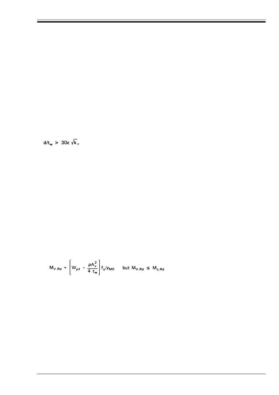
ENV 1993-1-1:1992
© BSI 04-2000
67
(3) For other cases A
v
should be determined analogously.
(4) For simplicity, the value of A
v
for a rolled I, H or channel section, load parallel to web, may be taken
as 1,04ht
w
.
(5) In appropriate cases the formulae in (2) may be applied to components of a built-up section.
(6) If the web thickness is not constant, t
w
should be taken as the minimum thickness.
(7) In addition the shear buckling resistance shall also be verified as specified in 5.6 when:
• for an unstiffened web:
d/t
w
> 69¼
• for a stiffened web:
where k
Ù
is the buckling factor for shear, see 5.6.3
(8) Fastener holes need not be allowed for in shear verifications provided that:
(9) When A
v.net
is less than this limit, an effective shear area of (f
u
/f
y
) A
v.net
may be assumed.
The block shear criterion given in 6.5.2.2 shall also be verified at the ends of a member.
5.4.7 Bending and shear
(1) The theoretical plastic resistance moment of a cross-section is reduced by the presence of shear. For
small values of the shear force this reduction is so small that it is counter-balanced by strain hardening
and may be neglected. However, when the shear force exceeds half the plastic shear resistance, allowance
shall be made for its effect on the plastic resistance moment.
(2) Provided that the design value of the shear force V
Sd
does not exceed 50 % of the design plastic shear
resistance V
p
=
.Rd
no reduction need be made in the resistance moments given by 5.4.5.2.
(3) When V
Sd
exceeds 50 % of V
p
=
.Rd
the design resistance moment of the cross-section should be reduced to
M
V.Rd
the reduced design plastic resistance moment allowing for the shear force, obtained as follows:
a) for cross-sections with equal flanges, bending about the major axis:
where Ô = (2V
Sd
/V
p
=
.Rd
– 1)
2
b) for other cases: M
V.Rd
should be taken as the design plastic resistance moment of the cross-section,
calculated using a reduced strength (1 – p) f
y
for the shear area, but not more than M
c.Rd
.
NOTE Paragraph (3) applies to Class 1, 2, 3 and 4 cross-sections. The appropriate value of M
c.Rd
should be used, see 5.4.5.2.
5.4.8 Bending and axial force
5.4.8.1 Class 1 and 2 cross-sections
(1) For class 1 and 2 cross-sections, the criterion to be satisfied in the absence of shear force is:
where M
N.Rd
is the reduced design plastic resistance moment allowing for the axial force.
r
is the root radius
t
f
is the flange thickness
and
t
w
is the web thickness
and ¼ = [235/f
y
]
0,5
(f
y
in N/mm
2
)
A
v.net
U (f
y
/f
u
) A
v
(5.21)
(5.22)
M
Sd
k M
N.Rd
(5.23)
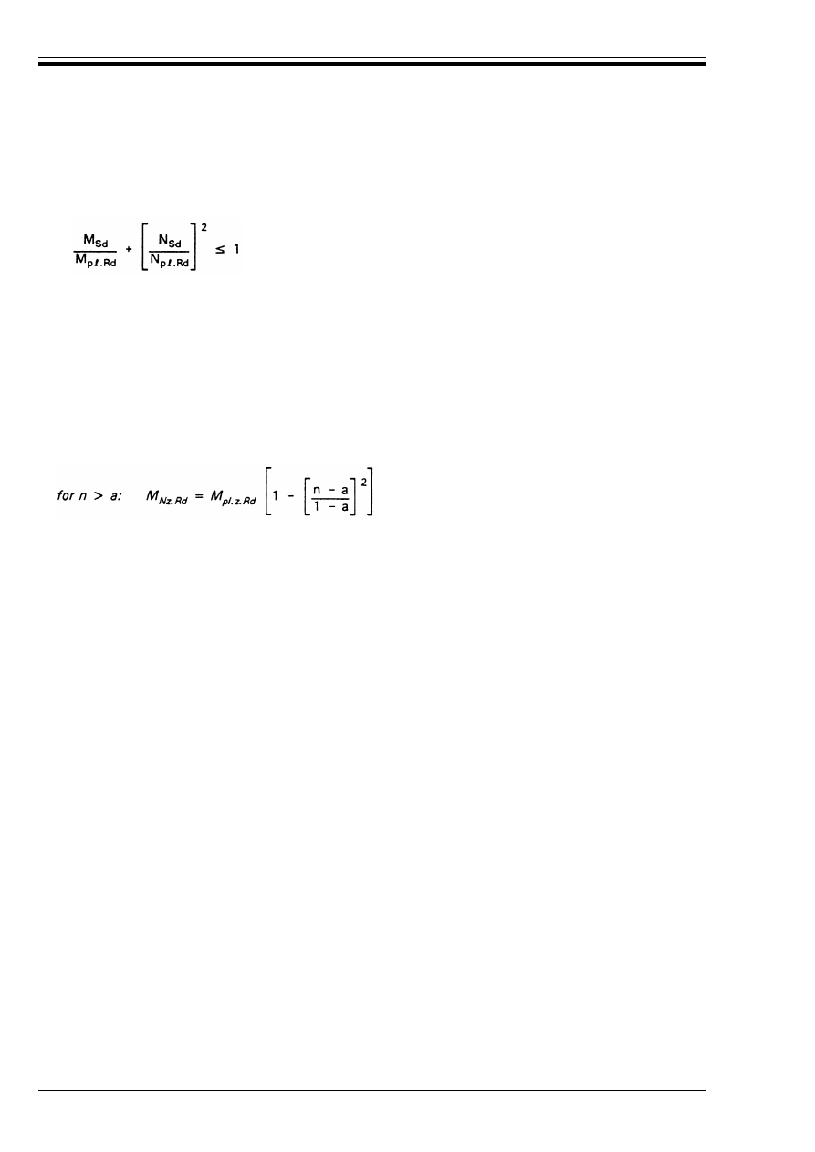
ENV 1993-1-1:1992
68
© BSI 04-2000
(2) For a plate without bolt holes, the reduced design plastic resistance moment is given by:
M
N.Rd
= M
p
=
.Rd
[1 – (N
Sd
/N
p
=
.Rd
)
2
]
and the criterion becomes:
(3) In flanged sections, the reduction of the theoretical plastic resistance moment by the presence of small
axial forces is counter-balanced by strain hardening and may be neglected. However, for bending about the
y-y-axis, allowance shall be made for the effect of the axial force on the plastic resistance moment when the
axial force exceeds half the plastic tension resistance of the web, or a quarter of the plastic tension
resistance of the cross-section, whichever is smaller. Similarly, for bending about the z-z-axis, allowance
shall be made for the effect of the axial force when it exceeds the plastic tension resistance of the web.
(4) For cross-sections without bolt holes, the following approximations may be used for standard rolled I or
H sections:
(5) The expressions given in (4) may also be used for welded I or H sections with equal flanges.
(6) The approximations given in (4) may be further simplified (for standard rolled I or H sections only) to:
(7) For cross-sections without bolt holes, the following approximations may be used for rectangular
structural hollow sections of uniform thickness:
(8) The expressions given in (7) may also be used for welded box sections with equal flanges and equal webs,
by taking:
a
w
= (A-2bt
f
)/A but a
w
k 0,5
a
f
= (A-2ht
w
)/A but a
f
k 0,5
(9) The approximations given in (7) may be further simplified for standard rectangular structural hollow
sections of uniform thickness, as follows:
• for a square section:
• for a rectangular section:
(10) For cross-sections without bolt holes, the following approximation may be used for circular tubes of
uniform thickness:
(5.24)
M
Ny.Rd
= M
p
=
.y.Rd
(1 – n)/(1 – 0,5a) but M
Ny.Rd
k M
p
=
.y.Rd
(5.25)
for n k a: M
Nz.Rd
k M
p
=
.z.Rd
(5.26)
where n = N
Sd
/N
p
=
.Rd
and
a = (A-2bt
f
)/A
but a k 0,5
M
Ny.Rd
= 1,11M
p
=
.y.Rd
(1 – n) but M
Ny.Rd
k M
p
=
.y.Rd
(5.27)
for n k 0,2: M
Nz.Rd
k M
p
=
.z.Rd
for n > 0,2:
M
Nz.Rd
= 1,56M
p
=
.z.Rd
(1 – n)(n + 0,6)
(5.28)
M
Ny.Rd
=
M
pt.y.Rd
(1 – n)/(1 – 0,5a
w
)
but M
Ny.Rd
k M
p
=
.y.Rd
(5.29)
M
Nz.Rd
=
M
p
=
.z.Rd
(1 – n)/(1 – 0,5a
f
)
but M
Nz.Rd
k M
p
=
.z.Rd
(5.30)
where a
w
=
(A – 2bt)/A
but a
w
k 0,5
and a
f
=
(A – 2ht)/A
M
N.Rd
= 1,26M
p
=
.Rd
(1 – n)
but M
N.Rd
k M
p
=
.Rd
(5.31)
M
Ny.Rd
= 1,33M
p
=
.y.Rd
(1 – n)
but M
Ny.Rd
k M
p
=
.y.Rd
(5.32)
M
Nz.Rd
= M
p
=
.z.Rd
(1 – n)/(0,5 + ht/A)
but M
Nz.Rd
k M
p
=
.z.Rd
(5.33)
M
N.Rd
= 1,04M
p
=
.Rd
(1 – n
1,7
)
but M
N.Rd
k M
p
=
.Rd
(5.34)
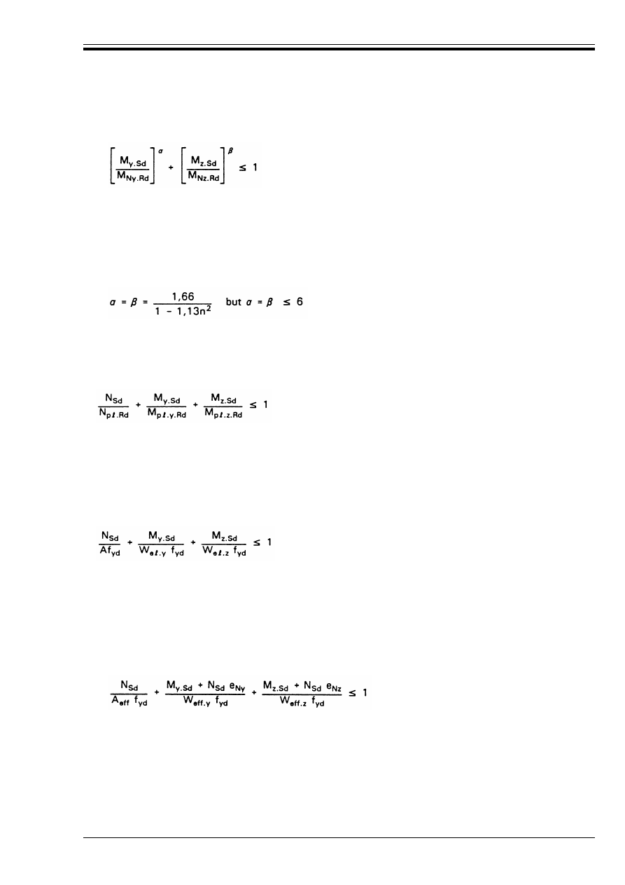
ENV 1993-1-1:1992
© BSI 04-2000
69
(11) For bi-axial bending the following approximate criterion may be used:
in which µ and ¶ are constants, which may conservatively be taken as unity, otherwise as follows:
• I and H sections:
µ = 2; ¶ = 5n but 
U 1
• circular tubes:
µ = 2; ¶ = 2
• rectangular hollow sections:
• solid rectangles and plates:
µ = ¶ = 1,73 + 1,8n
3
where n = N
Sd
/N
p
=
.Rd
(12) As a further conservative approximation, the following criterion may be used:
5.4.8.2 Class 3 cross-sections
(1) In the absence of shear force, Class 3 cross-sections will be satisfactory if the maximum longitudinal
stress Ö
x.Ed
satisfies the criterion:
where f
yd
= f
y
/¾
M0
(2) For cross-sections without holes for fasteners, the above criterion becomes:
5.4.8.3 Class 4 cross-sections
(1) In the absence of shear force, Class 4 cross-sections will be satisfactory if the maximum longitudinal
stress Ö
x.Ed
calculated using the effective widths of the compression elements [see 5.3.2(2)] satisfies the
criterion:
where f
yd
= f
y
/¾
M1
(2) For cross-sections without holes for fasteners, the above criterion becomes:
(5.35)
(5.36)
Ö
x.Ed
k f
yd
(5.37)
(5.38)
Ö
x.Ed
k f
yd
(5.39)
(5.40)
where
A
eff
is
the effective area of the cross-section when subject to uniform compression.
W
eff
is
the effective section modulus of the cross-section when subject only to moment about
the relevant axis.
e
N
is
the shift of the relevant centroidal axis when the cross-section is subject to uniform
compression.
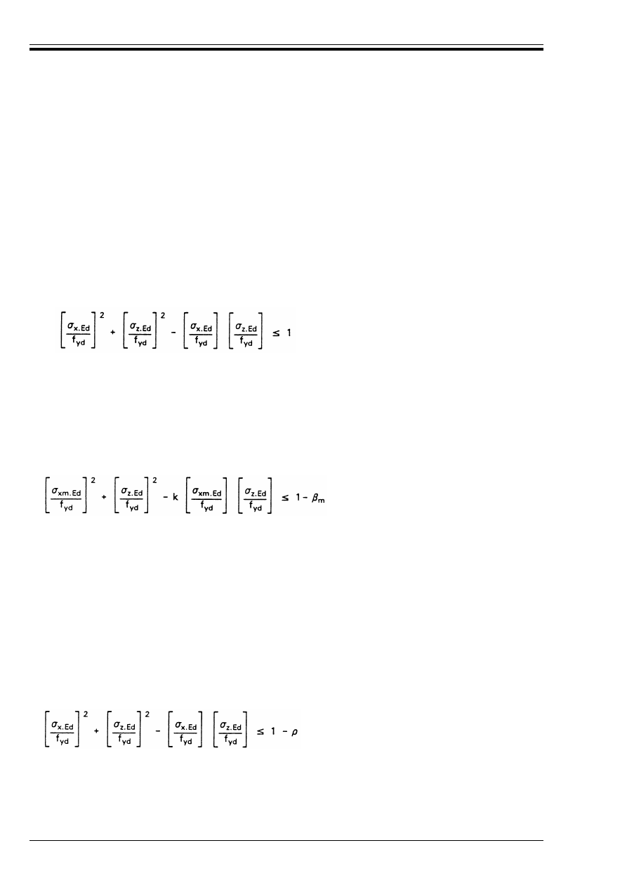
ENV 1993-1-1:1992
70
© BSI 04-2000
5.4.9 Bending, shear and axial force
(1) When the shear force exceeds half the plastic shear resistance, allowance shall be made for the effect of
both shear force and axial force on the reduced plastic resistance moment.
(2) Provided that the design value of the shear force V
Sd
does not exceed 50 % of the design plastic shear
resistance V
p
=
.Rd
no reduction need be made in combinations of moment and axial force that meet the criteria
in 5.4.8.
(3) When V
Sd
exceeds 50 % of V
p
=
.Rd
the design resistance of the cross-section to combinations of moment and
axial force should be calculated using a reduced yield strength (1 – Ô)f
y
for the shear area,
where Ô = (2V
Sd
/V
p
=
.Rd
– 1)
2
.
5.4.10 Transverse forces on webs
(1) In the absence of shear force, the web of a member subject to a transverse force in the plane of the web,
see Figure 5.4.3, in addition to any combination of moment and axial force on the cross-section, shall at all
points satisfy the following yield criterion:
In expression (5.41) above, Ö
x.Ed
and Ö
z.Ed
shall each be taken as positive for compression and negative for
tension.
(2) When the moment resistance is based on a plastic distribution of stresses in the cross-section, the above
criterion may be assumed to be satisfied when:
(3) Provided that the design value of the shear force V
Sd
does not exceed 50 % of the design plastic shear
resistance V
p
=
.Rd
, the criterion given in (2) may be adopted without any modification to allow for shear.
(4) When V
Sd
exceeds 50 % of V
p
=
.Rd
the yield criterion given in (1) should be modified to:
where Ô = (2V
Sd
/V
p
=
.Rd
– 1)
2
(5.41)
where Ö
x.Ed
is
the design value of the local longitudinal stress due to moment and axial force at the
point
Ö
z.Ed
is
the design value of the stress at the same point due to the transverse force
and
f
yd
= f
y
/¾
M0
(5.42)
where
Ö
xm.Ed
is the design value of the mean longitudinal stress in the web
m
= M
w.Sd
/M
pl.w.Rd
M
w.Sd
is the design value of the moment in the web
M
p
=
.w.Rd
= 0,25t
w
d
2
f
y
/¾
M0
and
k is obtained as follows:
for
Ö
xm.Ed
/Ö
z.Ed
k 0: k = 1 – 
m
for
Ö
xm.Ed
/Ö
z.Ed
> 0:
w
if 
m
k 0,5: k = 0,5 (1 + 
m
)
w
if 
m
> 0,5: k = 0,5 (1 – 
m
)
(5.43)
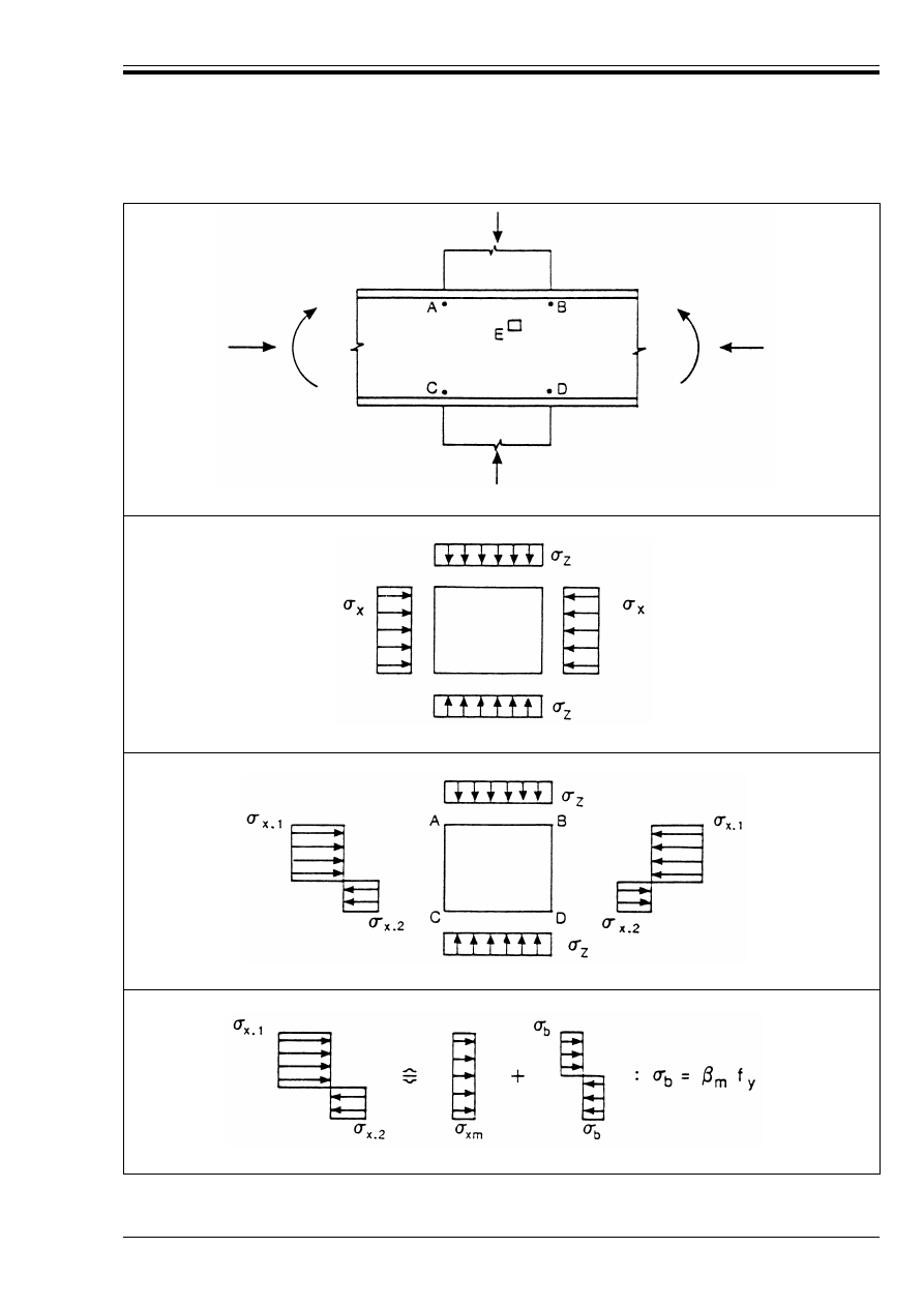
ENV 1993-1-1:1992
© BSI 04-2000
71
(a)Layout
(b) Stresses in element E
(c) Stresses in panel ABCD
(d) Approximate equivalent longitudinal stresses
Figure 5.4.3 — Stresses in web panel due to bending moment, axial force and
transverse force
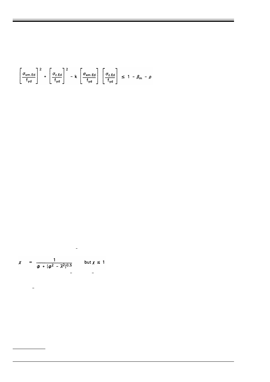
ENV 1993-1-1:1992
72
© BSI 04-2000
(5) When V
Sd
exceeds 50 % of V
p
=
.Rd
and the moment resistance is based on a plastic distribution of stresses
in the cross-section, the following approximate criterion may be adopted:
where k and 
m
are as defined in (2).
(6) The effective value of the transverse stress Ö
z.Ed
due to a point load should be determined by assuming it
to be uniformly distributed over a length s equal to the lesser of the depth d of the web and the spacing a of
the transverse web stiffeners.
(7) The effective value of the transverse stress Ö
z.Ed
due to a load distributed over a length between transverse
web stiffeners less than their spacing a should similarly be determined by assuming it to be distributed over
a length s determined as in (6).
(8) The effects of transverse compressive forces on the local buckling resistance of the web should be checked,
see 5.3.6.
(9) In addition the crippling resistance and the buckling resistance of the web should be checked, see 5.7.4
and 5.7.5.
5.5 Buckling resistance of members
5.5.1 Compression members
5.5.1.1 Buckling resistance
(1) The design buckling resistance of a compression member shall be taken as:
and · is the reduction factor for the relevant buckling mode.
(2) For hot rolled steel members with the types of cross-section commonly used for compression members,
the relevant buckling mode is generally “flexural” buckling.
(3) In some cases the “torsional” or “flexural-torsional” modes may govern. Reference may be made to
ENV 1993-1-3 Eurocode 3-1.3
17)
.
5.5.1.2 Uniform members
(1) For constant axial compression in members of constant cross-section, the value of · for the appropriate
non-dimensional slenderness , may be determined from:
(2) The imperfection factor µ corresponding to the appropriate buckling curve shall be obtained from
Table 5.5.1.
(5.44)
N
b.Rd
= · 
A
Af
y
/¾
M1
(5.45)
where 
A
= 1 for Class 1, 2 or 3 cross-sections
A
= A
eff
/A for Class 4 cross-sections
17)
In preparation
(5.46)
where
Ì
= 0,5 [1 + µ( – 0,2) +
2
]
µ
is an imperfection factor
= [
A
Af
y
/N
cr
]
0,5
= (Æ/Æ
1
) [
A
]
0,5
Æ
is the slenderness for the relevant buckling mode
Æ
1
= Ï [E/f
y
]
0,5
= 93,9¼
¼
= [235/f
y
]
0,5
(f
y
in N/mm
2
)
and
N
cr
is the elastic critical force for the relevant buckling mode.
Æ
Æ
Æ
Æ
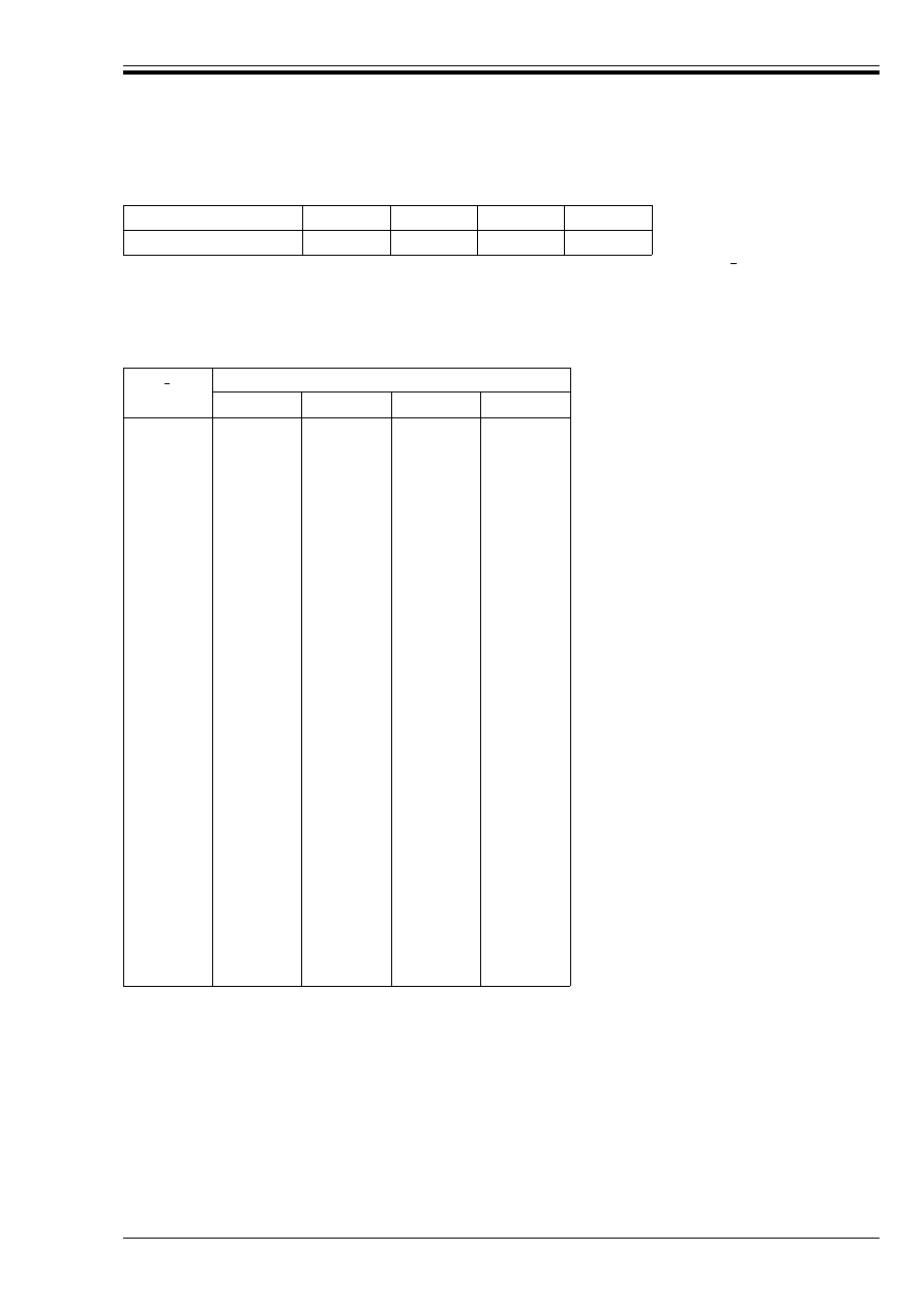
ENV 1993-1-1:1992
© BSI 04-2000
73
Table 5.5.1 — Imperfection factors
(3) Values of the reduction factor · for the appropriate non-dimensional slenderness may be obtained
from Table 5.5.2.
(4) Alternatively, uniform members may be verified using second order analysis, see 5.5.1.3(4)
and 5.5.1.3(6).
Table 5.5.2 — Reduction factors ·
5.5.1.3 Non-uniform members
(1) Tapered members and members with changes of cross-section within their length may be verified using
second order analysis, see (4) and (6).
(2) Alternatively, simplified methods of analysis may be based on modifications of the basic procedure for
uniform members.
(3) No one method is preferred. Any recognised method may be used provided that it can be demonstrated to
be conservative.
(4) Second order analysis of a member shall incorporate the appropriate equivalent initial bow imperfection
given in Figure 5.5.1 corresponding to the relevant buckling curve, depending on the method of analysis
and type of cross-section verification.
Bucking curve
a
b
c
d
Imperfection factor µ
0,21
0,34
0,49
0,76
Buckling curve
a
b
c
d
0,2
0,3
0,4
0,5
0,6
0,7
0,8
0,9
1,0
1,1
1,2
1,3
1,4
1,5
1,6
1,7
1,8
1,9
2,0
2,1
2,2
2,3
2,4
2,5
2,6
2,7
2,8
2,9
3,0
1,0000
0,9775
0,9528
0,9243
0,8900
0,8477
0,7957
0,7339
0,6656
0,5960
0,5300
0,4703
0,4179
0,3724
0,3332
0,2994
0,2702
0,2449
0,2229
0,2036
0,1867
0,1717
0,1585
0,1467
0,1362
0,1267
0,1182
0,1105
0,1036
1,0000
0,9641
0,9261
0,8842
0,8371
0,7837
0,7245
0,6612
0,5970
0,5352
0,4781
0,4269
0,3817
0,3422
0,3079
0,2781
0,2521
0,2294
0,2095
0,1920
0,1765
0,1628
0,1506
0,1397
0,1299
0,1211
0,1132
0,1060
0,0994
1,0000
0,9491
0,8973
0,8430
0,7854
0,7247
0,6622
0,5998
0,5399
0,4842
0,4338
0,3888
0,3492
0,3145
0,2842
0,2577
0,2345
0,2141
0,1962
0,1803
0,1662
0,1537
0,1425
0,1325
0,1234
0,1153
0,1079
0,1012
0,0951
1,0000
0,9235
0,8504
0,7793
0,7100
0,6431
0,5797
0,5208
0,4671
0,4189
0,3762
0,3385
0,3055
0,2766
0,2512
0,2289
0,2093
0,1920
0,1766
0,1630
0,1508
0,1399
0,1302
0,1214
0,1134
0,1062
0,0997
0,0937
0,0882
Æ
Æ

ENV 1993-1-1:1992
74
© BSI 04-2000
(5) The equivalent initial bow imperfections given in Figure 5.5.1 shall also be used where it is necessary
(according to 5.2.4.5) to include member imperfections in the global analysis.
(6) When the imperfections given in Figure 5.5.1 are used, the resistances of the cross-sections shall be
verified as specified in 5.4, but using ¾
M1
in place of ¾
M0
.
5.5.1.4 Flexural buckling
(1) For flexural buckling the appropriate buckling curve shall be determined from Table 5.5.3.
(2) Sections not contained in Table 5.5.3 shall be classified analogously.
(3) The slenderness Æ shall be taken as follows:
(4) Cold formed structural hollow sections shall be verified using either:
a) the basic yield strength f
yb
of the flat sheet material out of which the member is made by
cold-forming, with buckling curve b.
b) The average yield strength f
ya
of the member after cold-forming, determined in conformity with the
definition given in Figure 5.5.2, with buckling curve c.
5.5.1.5 Buckling length
(1) The buckling length = of a compression member with both ends effectively held in position laterally, may
conservatively be taken as equal to its system length L.
(2) Alternatively the buckling length = may be determined using informative Annex E.
Æ =
=/i
(5.47)
where i is the radius of gyration about the relevant axis, determined using the properties of the gross
cross-section.
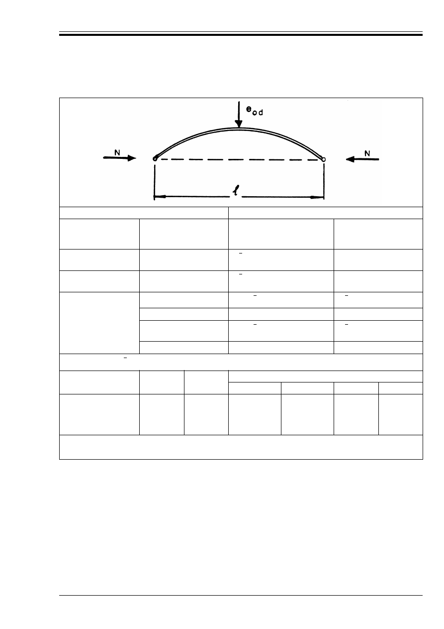
ENV 1993-1-1:1992
© BSI 04-2000
75
Cross-section
Method of global analysis
Method used to verify
resistance
Section type and axis
Elastic or
Rigid — Plastic or
Elastic — Perfectly plastic
Elasto-plastic
(plastic zone method)
Elastic
[5.4.8.2]
Any
µ(
– 0,2) k
¾
W
e
=
/A
—
Linear plastic
[5.4.8.1(12)]
Any
µ(
– 0,2) k
¾
W
p
=
/A
—
Non-linear plastic
[5.4.8.1(1) to (11)]
I-section yy-axis
1,33µ( – 0,2) k
¾
W
p
=
/A
µ(
– 0,2) k
¾
W
p
=
/A
I-section zz-axis
2,0 k
¾
e
eff
/¼
k
¾
e
eff
/¼
Rectangular hollow
section
1,33µ( – 0,2) k
¾
W
p
=
/A
µ(
– 0,2) k
¾
W
p
=
/A
Circular hollow section
1,5 k
¾
e
eff
/¼
k
¾
e
eff
/¼
k
¾
= (1 – k
¸
) + 2k
¸
but k
¾
U 1,0
Buckling curve
Ö
e
eff
k
¸
¾
M1
= 1,05
¾
M1
= 1,10
¾
M1
= 1,15
¾
M1
= 1,20
a
b
c
d
0,21
0,34
0,49
0,76
=/600
=/380
=/270
=/180
0,12
0,08
0,06
0,04
0,23
0,15
0,11
0,08
0,33
0,22
0,16
0,11
0,42
0,28
0,20
0,14
Non-uniform members:
Use value of W
e
=
/A or W
p
=
/A at centre of buckling length =
Figure 5.5.1 — Design values of equivalent initial bow imperfection e
o,d
Æ
Æ
Æ
Æ
Æ
Æ
Æ
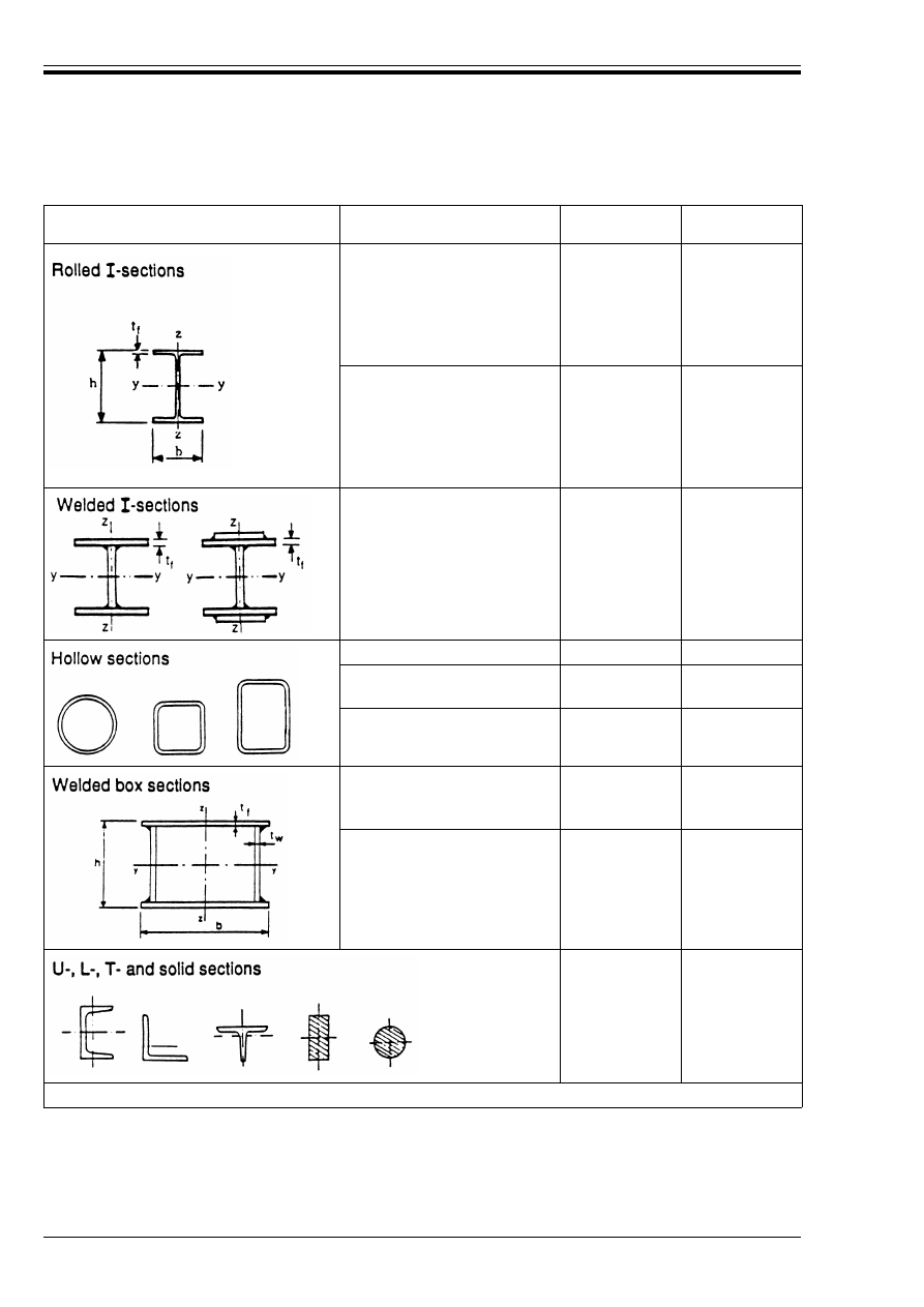
ENV 1993-1-1:1992
76
© BSI 04-2000
Table 5.5.3 — Selection of buckling curve for a cross-section
Cross section
Limits
Buckling about
axis
Buckling curve
h/b > 1,2:
t
f
k 40 mm
40 mm <t
f
k 100 mm
y – y
z – z
y – y
z – z
a
b
b
c
h/b k1,2:
t
f
k 100 mm
t
f
> 100 mm
y – y
z – z
y – y
z – z
a
b
d
d
t
f
k40 mm
t
f
> 40 mm
y – y
z – z
y – y
z – z
b
c
c
d
hot rolled
any
a
cold formed
— using f
yb
a
any
b
cold formed
— using f
ya
a
any
c
generally
(except as below)
any
b
thick welds and
b/t
f
< 30
h/t
W
< 30
y – y
z – z
c
c
any
c
a
See 5.5.1.4(4) and Figure 5.5.2
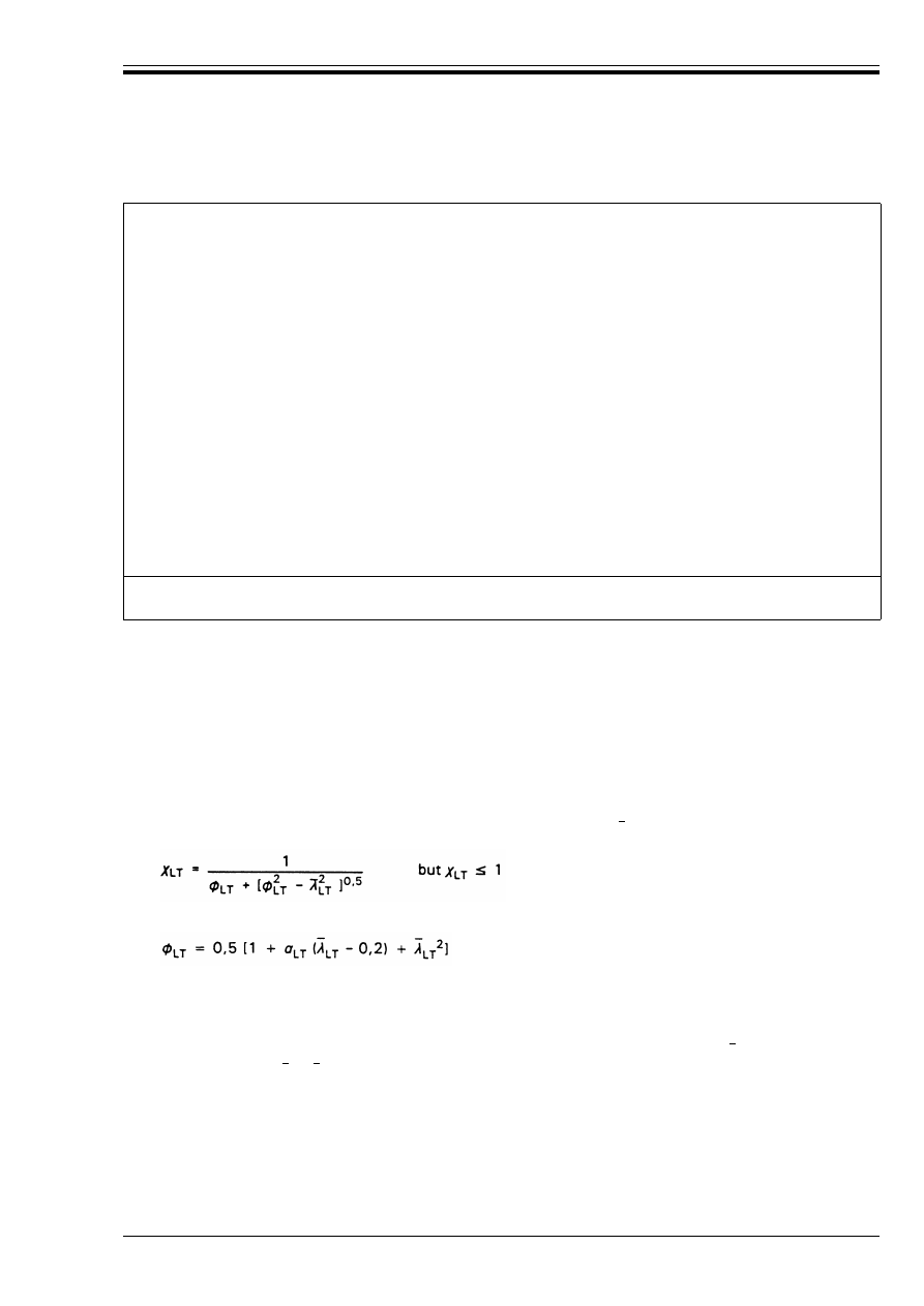
ENV 1993-1-1:1992
© BSI 04-2000
77
5.5.2 Lateral-torsional buckling of beams
(1) The design buckling resistance moment of a laterally unrestrained beam shall be taken as:
(2) The value of ·
LT
for the appropriate non-dimensional slenderness may be determined from:
(3) The values of the imperfection factor µ
LT
for lateral torsional buckling should be taken as:
µ
LT
= 0,21 for rolled sections
µ
LT
= 0,49 for welded sections
(4) Values of the reduction factor ·
LT
for the appropriate non-dimensional slenderness may be obtained
from Table 5.5.2 with and · = ·
LT
, using:
• for rolled sections:
curve a (µ = 0,21)
• for welded sections:
curve c (µ = 0,49)
Average yield strength:
The average yield strength f
ya
may be determined from full size section tests or as follows:
f
ya
= f
yb
+ (knt
2
/A
g
)(f
u
– f
yb
)
where:
f
yb
, f
u
t
A
g
k
is the tensile yield strength and tensile ultimate strength of the basic material as defined
below (N/mm
2
)
is the material thickness (mm)
is the gross cross-sectional area (mm
2
)
is the coefficient depending on the type of forming:
w
w
k = 7 for cold rolling
k = 5 for other methods of forming
n
is the number of 90° bend in the section with an internal radius < 5t (fractions of 90° bends
should be counted as fractions of n)
and f
ya
should not exceed f
u
or 1,2 f
yb
The increase in yield strength due to cold working should not be utilised for members which are welded,
annealed, galvanised (after forming) or subject to heat treatment after forming which may produce
softening.
Basic material:
Basic material is the flat sheet material out of which sections are made by cold-forming.
Figure 5.5.2 — Average yield strength f
ya
of cold formed structural hollow sections
M
b.Rd
= ·
LT
W
W
pl.y
f
y
/¾
M1
(5.48)
where
W
= 1 for Class 1 or Class 2 cross-sections
W
= W
el.y
/W
pl.y
for Class 3 cross-sections
W
= W
eff.y
/W
pl.y
for Class 4 cross-sections
and
·
LT
is the reduction factor for lateral-torsional buckling.
(5.49)
in which:
Æ
LT
Æ
LT
Æ
Æ
LT
=
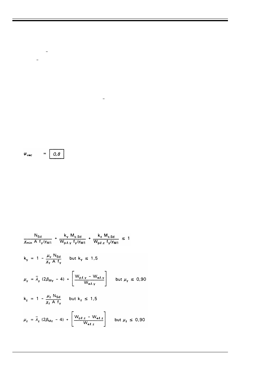
ENV 1993-1-1:1992
78
© BSI 04-2000
(5) The value of may be determined from:
(6) Information for the calculation of M
cr
(or for the direct calculation of Æ
LT
) is given in informative
Annex F.
(7) Where the non-dimensional slenderness k 0,4 no allowance for lateral-torsional buckling is
necessary.
(8) A beam with full restraint does not need to be checked for lateral-torsional buckling.
5.5.3 Bending and axial tension
(1) Members subject to combined bending and axial tension shall be checked for resistance to
lateral-torsional buckling, treating the axial force and bending moment as a vectorial effect, see 2.3.3.1(4).
(2) Where the axial force and bending moment can vary independently, the design value of the axial tension
should be multiplied by a reduction factor for vectorial effects:
(3) The not calculated stress Ö
com.Ed
(which can exceed f
¾
) in the extreme compression fibre due to the vectorial
effects should be determined from:
(4) The verification should be carried out using an effective design internal moment M
eff.Sd
obtained from:
M
eff.Sd
= W
com
Ö
com.Ed
(5) The design buckling resistance moment M
b.Rd
should be obtained using 5.5.2.
5.5.4 Bending and axial compression
(1) Members with Class 1 and Class 2 cross-sections subject to combined bending and axial compression
shall satisfy:
= [
W
W
p
=
.y
f
y
/M
cr
]
0,5
= [Æ
LT
/Æ
1
] [
W
]
0,5
where Æ
1
= Ï [E/f
y
]
0,5
= 93,9¼
¼
= [235/f
y
]
0,5
(f
y
in N/mm
2
)
and
M
cr
is the elastic critical moment for lateral-torsional buckling.
Ö
com.Ed
= M
Sd
/W
com
– Ò
vec
N
Ù
.Sd
/A
(5.50)
where
W
com
is the elastic section modulus for the extreme compression fibre
and
N
Ù
.Sd
is the design value of the axial tension
(5.51)
in which:
X
min
is the lesser of ·
y
and ·
z
where ·
y
and ·
z
are the reduction factors from 5.5.1 for the y-y and z-z axes respectively
and
My
and 
Mx
are equivalent uniform moment factors for flexural buckling, see (7).
Æ
LT
Æ
LT
Æ
LT
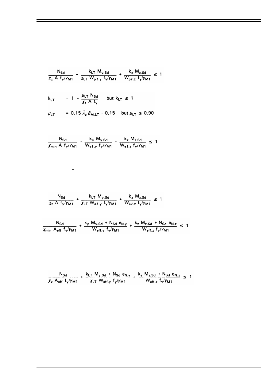
ENV 1993-1-1:1992
© BSI 04-2000
79
(2) Members with Class 1 and Class 2 cross-sections for which lateral-torsional buckling is a potential
failure mode shall also satisfy:
(3) where 
M.LT
is an equivalent uniform moment factor for lateral-torsional buckling, see (7).
Members with Class 3 cross-sections subject to combined bending and axial load shall satisfy:
(4) Members with Class 3 cross-sections for which lateral-torsional buckling is a potential failure mode
shall also satisfy:
(5) Members with Class 4 cross-sections subject to combined bending and axial load shall satisfy:
(6) Members with Class 4 cross-sections for which lateral-torsional buckling is a potential failure mode
shall also satisfy:
(7) The equivalent uniform moment factors 
M.y
, 
M.z
and "
M.LT
shall be obtained from Figure 5.5.3 according
to the shape of the bending moment diagram between the relevant braced points as follows:
(5.52)
in which:
(5.53)
where k
y
, k
z
and ·
min
are as in (1)
È
y
=
(2 
My
– 4) but È
y
k 0,90
and
È
z
=
(2 
Mz
– 4) but È
z
k 0,90
(5.54)
(5.56)
where k
y
, k
z
and ·
min
are as in (1)
È
y
and È
z
are as in (3)
and
A
eff
, W
eff.y
, W
eff.z
, e
Ny
and e
N.z
are as in 5.4.8.3.
(5.57)
factor:
moment
about axis:
points braced
in direction:
M.y
y-y
z-z
M.z
z-z
y-y
M.LT
y-y
y-y
Æ
y
Æ
z
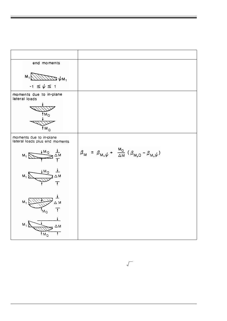
ENV 1993-1-1:1992
80
© BSI 04-2000
5.6 Shear buckling resistance
5.6.1 Basis
(1) Webs with d/t
w
greater than 69¼ for an unstiffened web, or 30¼
[see 5.4.6(7)] for a stiffened web,
shall be checked for resistance to shear buckling.
(2) The shear buckling resistance of a web depends on the depth-to-thickness ratio d/t
w
and the spacing of
any intermediate web stiffeners.
(3) The shear buckling resistance may also depend on the anchorage of tension fields by end stiffeners or
by flanges. The anchorage provided by flanges is reduced by longitudinal stresses due to bending moment
and axial load.
Moment diagram
Equivalent uniform moment factor
M
M,
Ò
= 1,8 – 0,7Ò
M,Q
= 1,3
M,Q
= 1,4
M
Q
= | max M|due to lateral load only
% M
|max M|
|max M|+|min M|
for moment diagram without
change of sign
for moment diagram with change
of sign
Figure 5.5.3 — Equivalent uniform moment factors
k
Ù
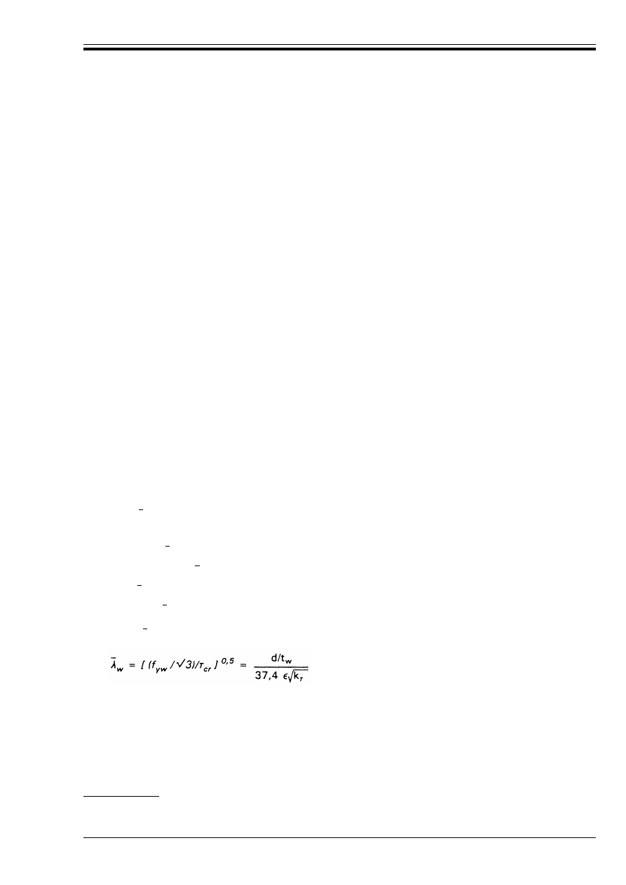
ENV 1993-1-1:1992
© BSI 04-2000
81
(4) All webs with d/t
w
greater than 69¼ shall be provided with transverse stiffeners at the supports.
5.6.2 Design methods
(1) For webs without intermediate transverse stiffeners and for webs with transverse stiffeners only, the
shear buckling resistance may be verified using either:
a) the simple post-critical method (see 5.6.3), or
b) the tension field method (see 5.6.4).
(2) Alternatively, the methods given in Part 2 of Eurocode 3 may be adopted.
(3) The simple post-critical method can be used for webs of I-section girders, with or without intermediate
transverse stiffeners, provided that the web has transverse stiffeners at the supports.
(4) The tension field method may be used for webs with transverse stiffeners at the supports plus
intermediate transverse stiffeners, provided that adjacent panels or end posts provide anchorage for the
tension fields. However it should not be used where:
(5) Where the transverse stiffeners are widely spaced, the tension field method becomes over-conservative. It
is not recommended for use where:
a/d > 3,0
(6) For both methods, intermediate transverse stiffeners should be checked as specified in 5.6.5 and welds
should be checked as specified in 5.6.6.
(7) For webs with longitudinal stiffeners refer to ENV 1993-2 Eurocode 3-2
18)
.
5.6.3 Simple post-critical method
(1) In the simple post-critical method, the design shear buckling resistance V
ba.Rd
should be obtained from:
where Ù
ba
is the simple post-critical shear strength.
(2) The simple post-critical shear strength Ù
ba
should be determined as follows:
a) when k 0,8:
= (f
yw
/Æ3)
b) when 0,8 <
< 1,2:
= [1 – 0,625 (
– 0,8)] (f
yw
/Æ3)
c) when U 1,2:
= [0,9/
] (f
yw
/Æ3)
in which is the web slenderness given by:
(3) The buckling factor for shear k
Ù
is given by the following:
• For webs with transverse stiffeners at the supports but no intermediate transverse stiffeners:
k
Ù
= 5,34
a/d < 1,0
where
a
is the clear spacing between transverse stiffeners
and
d
is the depth of the web
18)
In preparation.
V
ba.Rd
= d t
w
Ù
ba
/¾
M1
(5.58)
where
Ù
cr
is the elastic critical shear strength
and
k
Ù
is the buckling factor for shear.
Æ
w
Ù
ba
Æ
w
Ù
ba
Æ
w
Æ
w
Ù
ba
Æ
w
Æ
w
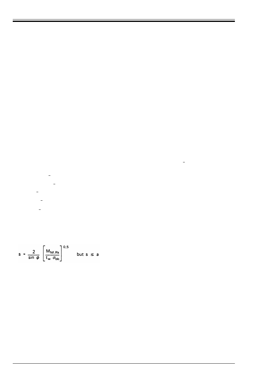
ENV 1993-1-1:1992
82
© BSI 04-2000
• For webs with transverse stiffeners at the supports and intermediate transverse stiffeners
with a/d < 1:
k
Ù
= 4 + 5,34/(a/d)
2
• For webs with transverse stiffeners at the supports and intermediate transverse stiffeners with
a/d U 1:
k
Ù
= 5,34 + 4/(a/d)
2
5.6.4 Tension field method
5.6.4.1 Shear buckling resistance
(1) In the tension field method, the design shear buckling resistance V
bb.Rd
should be obtained from:
(2) The initial shear buckling strength Ù
bb
should be determined as follows: when k 0,8:
a) Ù
bb
= (f
yw
/Æ3)
b) when 0,8 <
< 1,25:
Ù
bb
= [1 – 0,8 (
– 0,8)] (f
yw
/Æ3)
c) when U 1,25:
Ù
bb
= [1/
w
2
] (f
yw
/Æ3)
In which is as given in 5.6.3(2).
(3) The width of the tension field g is given by:
g = d cos Ì – (a – s
c
– s
t
) sin Ì
where s
c
and s
t
are the anchorage lengths of the tension field along the compression and tension flanges
respectively, obtained from:
where M
Nf.Rk
is the reduced plastic resistance moment of the flange.
(4) When calculating the plastic resistance moment of a flange, any lips or flange stiffeners should be
neglected. The reduced plastic resistance moment M
Nf.Rk
allowing for the longitudinal force N
f.Sd
in the flange
(due to the moment M
Sd
and any axial force N
Sd
in the member), is given by:
where b and t
f
are the width and thickness of the relevant flange.
V
bb.Rd
= [(d t
w
Ù
bb
) + 0,9 (g t
w
Ö
bb
sin Ì)]/¾
M1
(5.59)
where
Ö
bb
is the strength of the tension field, obtained from:
Ö
bb
= [f
yw
2
– 3Ù
bb
2
+ Ò
2
]
0,5
– Ò
in which Ò is 1,5Ù
bb
sin 2Ì
where
Ì
is the inclination of the tension field
g
is the width of the tension field, see Figure 5.6.1
and
Ù
bb
is the initial shear buckling strength.
M
Nf.Rk
= 0,25 bt
f
2
f
yf
[1 – [N
f.Sd
/(bt
f
f
yf
/¾
M0
)]
2
]
(5.60)
Æ
w
Æ
w
Æ
w
Æ
w
Æ
Æ
w
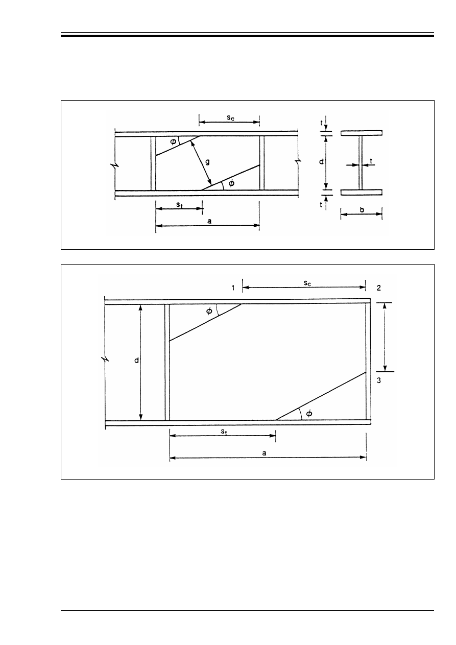
ENV 1993-1-1:1992
© BSI 04-2000
83
5.6.4.2 Inclination of the tension field
(1) The inclination of the tension field Ì varies between a minimum of G/2 and a maximum of G where G is
the slope of the panel diagonal given by:
G = arctan (d/a)
(2) The minimum value G/2 applies when the flanges are fully utilised in resisting the bending moment in
the member. The maximum value of G applies to the complete tension field condition with s = a.
(3) The appropriate value of Ì in any other case is the value (between the limits G/2 and G), which gives the
maximum value of the design shear buckling resistance V
bb.Rd
.
(4) Any other value of Ì (between the limits G/2 and G) is conservative. As an approximation Ì = G/1,5 may
be assumed. Alternatively, iteration may be used to find the optimum value of Ì.
Figure 5.6.1 — Tension field geometry
Figure 5.6.2 — End panel geometry
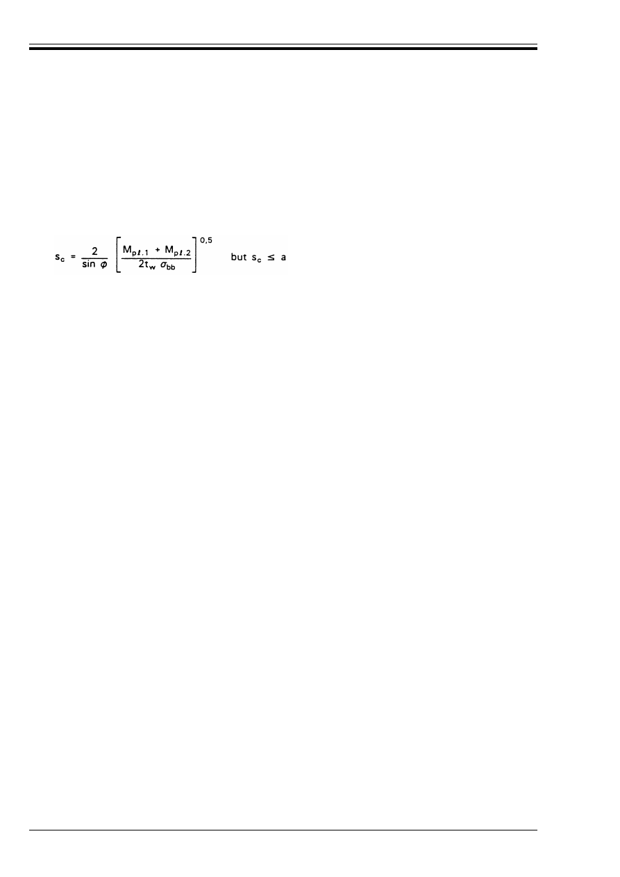
ENV 1993-1-1:1992
84
© BSI 04-2000
5.6.4.3 End panels
(1) Unless a suitable end post is supplied to anchor the tension field, end panels should be designed using
the simple post-critical method given in 5.6.3.
(2) When a suitable end post which satisfies the criterion given in (4) is used, the design shear buckling
resistance should be determined as given in 5.6.4.1, except that the anchorage length s
c
should be obtained
from (3), see Figure 5.6.2.
(3) When a single plate end post of breadth b
s
and thickness t
s
is used, the anchorage length s
c
should be
determined from:
(4) A single plate end post required to resist the tension field anchorage force F
bb
should satisfy the criterion:
(5) If an end post does not satisfy the criterion in (4), an increased value of Ì may be adopted such that the
anchorage length s
s
is reduced sufficiently for the criterion to be satisfied, provided that a reduced value of
the shear buckling resistance is then determined for the end panel corresponding to this increased value of Ì.
5.6.4.4 End post details
(1) The welds connecting the end post to the top flange should be designed to resist M
p
=
.2
, F
bb
and N
s2
.
(2) A twin-stiffener type of end post may be used as an alternative to the single plate type shown in
Figure 5.6.2, provided that the design expressions given in 5.6.4.3 are adjusted accordingly.
5.6.5 Intermediate transverse stiffeners
(1) For both the simple post-critical method and the tension field method, the compression force N
s
in an
intermediate transverse stiffener should be obtained from:
in which Ù
bb
is the initial shear buckling strength from 5.6.4.1(2); the lower value of Ù
bb
for the two panels
adjacent to the stiffener should be used.
(2) The buckling resistance of the stiffeners should be determined as specified in 5.7.6.
(3) The second moment of area of an intermediate transverse stiffener should satisfy the following:
if a/d < Æ2:
if a/d U Æ2:
(5.61)
where
M
p
=
.1
= 0,25bt
f
2
f
yf
[1 – [N
f1
/(bt
f
f
yf
)]
2
]
N
f1
= g t
w
Ö
bb
cos Ì
M
p
=
.2
is the lesser of M
Nf
and M
Ns
M
Nf
= 0,25 bt
f
2
f
yf
[1 – [F
bb
/(bt
f
f
yf
)]
2
]
M
Ns
= 0,25 b
s
t
s
2
f
ys
[1 – [N
s2
/(b
s
t
s
f
ys
)]
2
]
F
bb
= t
w
s
s
Ö
bb
cos
2
Ì
N
s2
= t
w
s
c
Ö
bb
sin
2
Ì
and
s
s
= d – (a – s
t
) tan Ì
M
p
=
.2
+ M
p
=
.3
U 0,5F
bb
s
s
(5.62)
where
M
p
=
.3
= 0,25 b
s
t
s
2
f
ys
[1 – [N
s3
/(b
s
t
s
f
ys
)]
2
]
and
N
s3
= V
Sd
– Ù
bb
t
w
(d – s
s
)
N
s
= V
Sd
– d t
w
Ù
bb
/¾
M1
but N
s
U 0
(5.63)
l
s
U 1,5d
3
t
w
3
/a
2
(5.64)
l
s
U 0,75dt
w
3
(5.65)
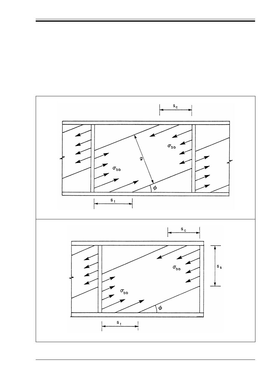
ENV 1993-1-1:1992
© BSI 04-2000
85
5.6.6 Welds
(1) The forces used to check the web-to-flange welds shall be compatible with the stress fields in the web
panels according to the method used to determine the shear buckling resistance.
(2) The design of the web-to-stiffener welds should also be consistent with the design assumptions for the web
panels.
(3) The tensile stresses in the web panels for the tension field method are indicated in Figure 5.6.3.
(a) Internal panel
(b) End panel
Figure 5.6.3 — Tension field stresses

ENV 1993-1-1:1992
86
© BSI 04-2000
5.6.7 Interaction between shear force, bending moment and axial force
5.6.7.1 General
(1) Provided that the flanges can resist the whole of the design values of the bending moment and axial force
in the member, the design shear resistance of the web need not be reduced to allow for the moment and axial
force in the member, except as given in 5.6.4.1(4) for the tension field method.
(2) For the procedure in other cases, refer to:
• 5.6.7.2 for the simple post-critical method.
• 5.6.7.3 for the tension field method.
5.6.7.2 Simple post-critical method
(1) The cross-section may be assumed to be satisfactory, without investigating the effect of the shear force on
the design moment resistance, if both the following criteria are satisfied:
When an axial force N
Sd
is also applied, the value of M
f.Rd
should be reduced accordingly, see 5.4.8.
(2) Provided that V
Sd
does not exceed 50 % of V
ba.Rd
the design resistance of the cross-section to bending
moment and axial force need not be reduced to allow for the shear force.
(3) When V
Sd
exceeds 50 % of V
ba.Rd
the following criterion should be satisfied:
If an axial force N
Sd
is also applied, then M
p
=
.Rd
should be replaced by the reduced plastic resistance moment
M
N.Rd
(see 5.4.8).
NOTE Paragraph (3) applies to Class 1, 2, 3 and 4 cross-sections, provided that the design resistance appropriate for that class of
cross-section in the absence of shear force is not exceeded.
(4) The interaction between shear force and bending moment is illustrated in Figure 5.6.4(a).
M
Sd
k M
f.Rd
(5.66a)
and
V
Sd
k V
ba.Rd
(5.66b)
where
M
f.Rd
is the design plastic moment resistance of a cross-section consisting of the flanges
only, taking account of the effective width b
eff
of the compression flange, see 5.3.5.
and
V
ba.Rd
is the design shear buckling resistance from 5.6.3.
M
Sd
k M
f.Rd
+ (M
p
=
.Rd
– M
f.Rd
) [1 – (2 V
Sd
/V
ba.Rd
– 1)
2
]
(5.67)
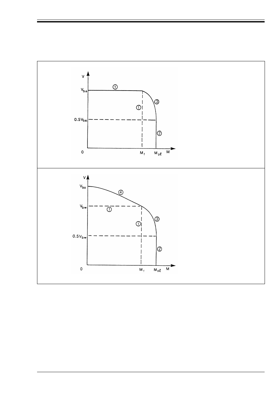
ENV 1993-1-1:1992
© BSI 04-2000
87
5.6.7.3 Tension field method
(1) The cross-section may be assumed to be satisfactory, without investigating the effect of the shear force on
the design moment resistance, if both the following criteria are satisfied:
When an axial force N
Sd
is also applied, the value of M
f.Rd
should be reduced accordingly, see 5.4.8.
e See 5.6.7.2(1)
f See 5.6.7.2(2)
g See 5.6.7.2(3)
(a) Simple post-critical method
e See 5.6.7.3(1) to (3)
f See 5.6.7.3(4)
g See 5.6.7.3(5)
h See 5.6.7.3(6)
(b) Tension field method
Figure 5.6.4 — Interaction of shear buckling resistance and moment resistance
M
Sd
k M
f.Rd
(5.68a)
and
V
Sd
kV
bw.Rd
(5.68b)
where
M
sd
and V
Sd
are each taken as the maximum respective value within the panel between adjacent
transverse web stiffeners
M
f.Rd
is as given in 5.6.7.2(1)
and V
bw.Rd
is the “web only” shear buckling resistance.

ENV 1993-1-1:1992
88
© BSI 04-2000
(2) The “web only” shear buckling resistance V
bw.Rd
is the specific value of V
bb.Rd
from 5.6.4 for the case where
the flanges are resisting a moment M
Sd
equal to M
f.Rd
and consequently in 5.6.4.1(4) the reduced plastic
resistance moment of the flange M
Nf.Rk
= 0.
(3) For a section with equal flanges and no axial force, V
bw.Rd
should be calculated assuming:
s
c
= s
t
= 0
and Ì = G/2
(4) Provided that V
Sd
does not exceed 50 % of V
bw.Rd
the design resistance of the cross-section to bending
moment and axial force need not be reduced to allow for the shear force.
(5) When V
Sd
exceeds 50 % of V
bw.Rd
but does not exceed V
bw.Rd
the following criterion should be satisfied:
When an axial force N
Sd
is also applied, then M
p
=
.Rd
should be replaced by the reduced plastic resistance
moment M
N.Rd
(see 5.4.8).
NOTE Paragraph (5) applies to Class 1, 2, 3 and 4 cross-sections, provided that the design resistance appropriate for that class of
cross-section in the absence of shear force is not exceeded.
(6) When V
Sd
exceeds V
bw.Rd
the following criterion should be satisfied:
where V
bb.Rd
is obtained from 5.6.4.1, taking account of M
Sd
and N
Sd
in 5.6.4.1(4).
(7) The interaction between shear force and bending moment is illustrated in Figure 5.6.4(b).
(8) In this figure, V
bo.Rd
is the specific value of V
bb.Rd
for the case where M
Sd
= 0.
5.7 Resistance of webs to transverse forces
5.7.1 Basis
(1) The resistance of an unstiffened web to transverse forces applied through a flange, is governed by one
of the following modes of failure:
• crushing of the web close to the flange, accompanied by plastic deformation of the flange,
• crippling of the web in the form of localised buckling and crushing of the web close to the flange,
accompanied by plastic deformation of the flange.
• buckling of the web over most of the depth of the member
(2) A distinction is made between two types of load application, as follows:
• Forces applied through one flange and resisted by shear forces in the web, see Figure 5.7.1(a).
• Forces applied to one flange and transferred through the web directly to the other flange,
see Figure 5.7.1(b).
(3) Where forces are applied through one flange and resisted by shear forces in the web, the resistance of the
web to transverse forces should be taken as the smaller of:
• the crushing resistance (see 5.7.3).
• the crippling resistance (see 5.7.4).
(4) Where forces are applied to one flange and transferred through the web directly to the other flange, the
resistance of the web to transverse forces should be taken as the smaller of:
• the crushing resistance (see 5.7.3).
• the buckling resistance (see 5.7.5).
(5) Where, in a practical case, the details are such that there is doubt over which mode governs, all three
modes should be considered.
(6) In addition the effect of the transverse force on the moment resistance of the member should be considered,
see 5.3.6 and 5.4.10.
(7) The crippling resistance of a stiffened web between the locations of transverse web stiffeners, is basically
similar to that of an unstiffened web, with some increase due to the presence of the stiffeners.
M
Sd
kM
f.Rd
+ (M
pt.Rd
– M
f.Rd
) [1 – (2V
Sd
/V
bw.Rd
– 1)
2
]
(5.69)
V
Sd
kV
bb.Rd
(5.70)
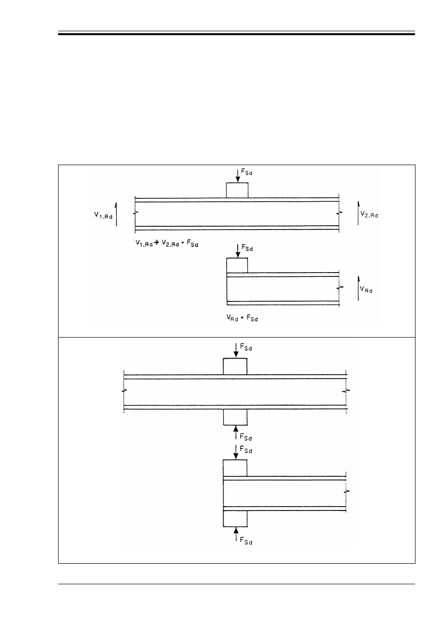
ENV 1993-1-1:1992
© BSI 04-2000
89
5.7.2 Length of stiff bearing
(1) The length of stiff bearing on the flange is the distance over which the applied force is effectively
distributed.
(2) The resistance of the web to transverse forces is influenced by the length of stiff bearing.
(3) The length of stiff bearing s
s
should be determined by dispersion of load through solid steel material
which is properly fixed in place at a slope of 1 : 1, see Figure 5.7.2. No dispersion should be taken through
loose packs.
(a) Forces resisted by shear in the web
(b) Forces transmitted directly through the web
Figure 5.7.1 — Forces applied through a flange
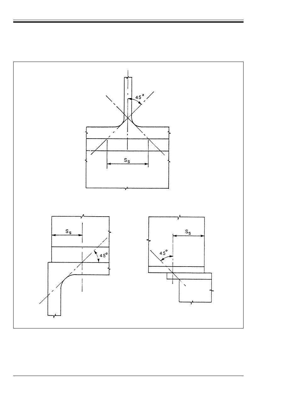
ENV 1993-1-1:1992
90
© BSI 04-2000
Figure 5.7.2 — Length of stiff bearing
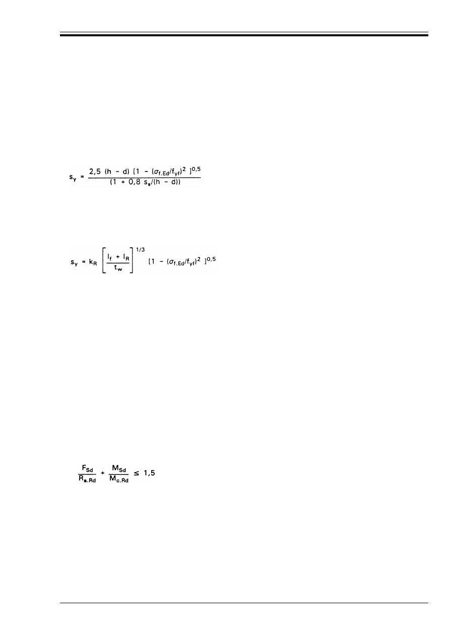
ENV 1993-1-1:1992
© BSI 04-2000
91
5.7.3 Crushing resistance
(1) The design crushing resistance R
y.Rd
of the web of an I, H or U section should be obtained from:
in which s
y
is given by:
but b
f
should not be taken as more than 25t
f
where Ö
f.Ed
is the longitudinal stress in the flange.
(2) For a rolled I, H or U section s
y
may alternatively be obtained from:
(3) At the end of a member s
y
should be halved.
(4) For wheel loads from cranes, transmitted through a crane rail bearing on a flange but not welded to it,
the design crushing resistance of the web R
y.Rd
should be taken as:
in which:
or more approximately:
• when the crane rail is mounted directly on the flange, k
R
= 3,25
• when a suitable resilient pad not less than 5 mm thick is interposed between the crane rail and the
beam flange: k
R
= 4,0
5.7.4 Crippling resistance
(1) The design crippling resistance R
a.Rd
of the web of an I, H or U section should be obtained from:
(2) Where the member is also subject to bending moments, the following criteria should be satisfied:
5.7.5 Buckling resistance
(1) The design buckling resistance R
b.Rd
of the web of an I, H or U section should be obtained by considering
the web as a virtual compression member with an effective breadth b
eff
obtained from:
(2) Near the ends of a member (or at openings in the web) the effective breadth b
eff
should not be taken as
greater than the breadth actually available, measured at mid-depth, see Figure 5.7.3.
(3) The buckling resistance should be determined from 5.5.1 using buckling curve c and 
A
= 1.
(4) The buckling length of the virtual compression member should be determined from the conditions of
lateral and rotational restraint at the flanges at the point of load application.
(5) The flange through which the load is applied should normally be restrained in position at the point of
load application. Where this is not practicable, a special buckling investigation should be carried out.
R
y.Rd
= (s
s
+ s
y
) t
w
f
yw
/¾
M1
(5.71)
s
y
= 2t
f
(b
f
/t
w
)
0,5
[f
yf
/f
yw
]
0,5
[1 – (Ö
f.Ed
/f
yf
)
2
]
0,5
(5.72)
(5.73)
R
y.Rd
= s
y
t
w
f
yw
/¾
M1
(5.74)
(5.75)
s
y
= 2(h
R
+ t
f
) [1 – (Ö
f.Ed
/f
yf
)
2
]
0,5
(5.76)
where
h
R
is the height of the crane rail
l
f
is the second moment of area of the flange about its horizontal centroidal axis
l
R
is the second moment of area of the crane rail about its horizontal centroidal axis
and
k
R
is a constant taken as follows:
R
a.Rd
= 0,5t
w
2
(Ef
yw
)
0,5
[(t
f
/t
w
)
0,5
+ 3(t
w
/t
f
)(s
s
/d)]/¾
M1
(5.77)
where s
s
is the length of stiff bearing from 5.7.2(3)
but
s
s
/d should not be taken as more than 0,2.
F
Sd
kR
a.Rd
(5.78a)
M
Sd
k M
c.Rd
(5.78b)
and
(5.78c)
b
eff
= [h
2
+ s
s
2
]
0,5
(5.79)
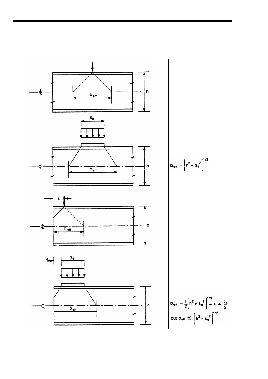
ENV 1993-1-1:1992
92
© BSI 04-2000
b
eff
= h
b
eff
=
but b
eff
k h
Figure 5.7.3 — Effective breadth for web buckling resistance
h
2
--- a
+
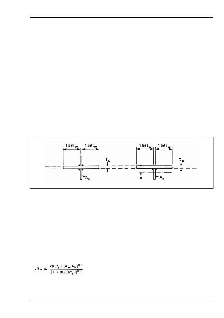
ENV 1993-1-1:1992
© BSI 04-2000
93
5.7.6 Transverse stiffeners
(1) When checking the buckling resistance, the effective cross-section of a stiffener should be taken as
including a width of web plate equal to 30¼t
w
, arranged with 15¼t
w
each side of the stiffener,
see Figure 5.7.4. At the ends of the member (or openings in the web) the dimension of 15¼t
w
should be limited
to the actual dimension available.
(2) The out-of-plane buckling resistance should be determined from 5.5.1, using buckling curve c and a
buckling length = of not less than 0,75d, or more if appropriate for the conditions of restraint.
(3) End stiffeners and stiffeners at internal supports should normally be double sided and symmetric about
the centreline of the web.
(4) Stiffeners at locations where significant external forces are applied should preferably be symmetric.
(5) Where single sided or other asymmetric stiffeners are used, the resulting eccentricity should be allowed
for, using clause 5.5.4.
(6) In addition to checking the buckling resistance, the cross-section resistance of a load bearing stiffener
should also be checked adjacent to the loaded flange. The width of web plate included in the effective
cross-section should be limited to s
y
(see 5.7.3) and allowance should be made for any openings cut in the
stiffener to clear the web-to-flange welds.
(7) For intermediate transverse stiffeners it is only necessary to check the buckling resistance, provided that
they are not subject to external loads.
5.7.7 Flange induced buckling
(1) To prevent the possibility of the compression flange buckling in the plane of the web, the ratio d/t
w
of
the web shall satisfy the following criterion:
(2) The value of the factor k should be taken as follows:
Class 1 flanges: 0,3
Class 2 flanges: 0,4
Class 3 or Class 4 flanges: 0,55
(3) When the girder is curved in elevation, with the compression flange on the concave face, the criterion
should be modified to:
where r is the radius of curvature of the compression flange.
(4) When the girder has transverse web stiffeners, the limiting value of d/t
w
may be increased accordingly.
Figure 5.7.4 — Effective cross-section of stiffeners
d/t
w
= k (E/f
yf
)[A
w
/A
fc
]
0,5
(5.80)
where
A
w
is the area of the web
A
fc
is the area of the compression flange
and
f
yf
is the yield strength of the compression flange.
(5.81)

ENV 1993-1-1:1992
94
© BSI 04-2000
5.8 Triangulated structures
5.8.1 General
(1) Triangulated structures such as lattice girders and triangulated bracing subject to predominantly static
loading may be analysed by assuming that the member ends are nominally pin-jointed.
(2) The buckling resistance of the compression members in such structures may be determined from 5.5.1
for compression members or 5.5.4 bending and axial compression. The buckling length may be determined
from 5.8.2. For built-up compression members, see section 5.9.
(3) For the design of angles as web members, see 5.8.3.
(4) For the design of lattice towers and masts see ENV 1993-3 Eurocode 3-3
19)
.
5.8.2 Buckling length of members
(1) For chord members generally and for out-of-plane buckling of web members, the buckling length = shall
be taken as equal to the system length L, unless a smaller value is justified by analysis.
(2) Web members may be designed for in-plane buckling using a buckling length smaller than the system
length, provided that the chords supply appropriate end restraint and the end connections supply
appropriate fixity (at least 2 bolts if bolted).
(3) Under these conditions, in normal triangulated structures the buckling length = of web members for
in-plane buckling may be taken as 0,9L, except for angle sections.
(4) For angle sections used as web members in compression see 5.8.3.
5.8.3 Angles as web members in compression
(1) Provided that the chords supply appropriate end restraint to the web members and the end connections
of the web members supply appropriate fixity (at least two bolts if bolted), the eccentricities may be neglected
and end fixities allowed for in the design of angles used as web members in compression, by using an effective
slenderness ratio obtained as follows:
where is as defined in 5.5.1.2 and the axes are as defined in Figure 1.1.
(2) This modified slenderness ratio should be used with buckling curve c in 5.5.1 to determine the
buckling resistance.
(3) When only single bolts are used for end connections of angle web members or when the end connection
has poor stiffness, the eccentricity should be taken into account using 5.5.4 and the buckling length = should
be taken as equal to the system length L.
5.9 Built-up compression members
5.9.1 Basis
(1) Built-up compression members consisting of two or more main components connected together at
intervals to form a single compound member shall be designed incorporating an equivalent geometric
imperfection comprising an initial bow e
o
of not less than =/500.
(2) The deformation of the compound member shall be taken into account in determining the internal forces
and moments in the main components, internal connections and any subsidiary components such as lacings
or battens.
(3) The design of the main and subsidiary components shall be checked using the methods given in 5.4
and 5.5. The design of the internal connections shall be checked using Chapter 6.
(4) The design procedures given in 5.9.2 to 5.9.5 apply only to built-up members with two main components,
except where it is explicitly stated that they can be applied to members with more than two main components.
19)
To be prepared at a later stage
for buckling about the v-v axis:
= 0,35 + 0,7
(5.82)
for buckling about the y-y axis:
= 0,50 + 0,7
(5.83)
for buckling about the z-z axis:
= 0,50 + 0,7
(5.84)
Æ
eff
Æ
eff.v
Æ
v
Æ
eff.y
Æ
y
Æ
eff.z
Æ
z
Æ
Æ
eff

ENV 1993-1-1:1992
© BSI 04-2000
95
(5) In addition to the axial forces, allowance should also be made for any other forces or moments applied to
the member, such as the effects of the self-weight or wind resistance of the member.
5.9.2 Laced compression members
5.9.2.1 Application
(1) The design procedure given in this sub-clause is for a design compressive force N
Sd
applied to a
built-up member consisting of two similar parallel chords of uniform cross section, with a fully triangulated
system of lacing which is uniform throughout the length of the member.
(2) The chords may be solid members or may themselves be laced or battened in the perpendicular plane.
(3) Where variations on the above are necessary, the procedure should be supplemented or modified as
appropriate.
5.9.2.2 Constructional details
(1) Where possible, single lacing systems on opposite sides of the main components shall be corresponding
systems as shown in Figure 5.9.1(a), arranged so that one is in the shadow of the other.
(2) Single lacing systems on opposite sides of the main components shall not be mutually opposed in
direction as shown in Figure 5.9.1(b), unless the resulting torsional deformation of the main components
can be accepted.
(3) Tie panels shall be provided at the ends of lacing systems, at points where the lacing is interrupted and
at connections with other members.
(4) Tie panels may take the form of battens conforming with 5.9.3.2; alternatively cross braced panels of
similar rigidity may be used.
(5) Except for these tie panels, if other components perpendicular to the longitudinal axis of the member
are combined with double intersection lacing systems [see Figure 5.9.2(a)], or single intersection lacing
systems mutually opposed in direction on opposite sides of the main components [see Figure 5.9.2(b)], the
resulting internal forces produced in the lacings due to the continuity of the main components shall be
determined and allowed for in the design of the lacings and their end connections.
(6) The lacings shall be positively connected to the main components, either by fasteners or by welding.
5.9.2.3 Second moment of area
(1) The effective second moment of area l
eff
of a laced compression member with two main components should
be taken as:
5.9.2.4 Chord forces at mid-length
(1) The chord force N
f.Sd
at mid-length should be determined from:
(2) Values of S
v
for various lacing systems are given in Figure 5.9.3.
5.9.2.5 Buckling resistance of chords
(1) The buckling length of a chord in the plane of a lacing system should be taken as the system length a
between lacing connections.
(2) In a member with four chords made of equal-leg angles with lacing in both directions, the buckling
length = for buckling about the weakest axis depends on the arrangement of the lacings, see Figure 5.9.4.
l
eff
= 0,5 h
o
2
A
f
(5.85)
where
A
f
is the cross-sectional area of one chord
and
h
o
is the distance between centroids of chords.
N
f.Sd
= 0,5 N
Sd
+ M
s
/h
o
(5.86)
where
M
s
= N
Sd
e
o
/(1 – N
Sd
/N
cr
– N
Sd
/S
v
)
e
o
= =/500 (see 5.9.1)
N
cr
= Ï
2
El
eff
eff
/=
2
and
S
v
is the shear stiffness of the lacings (the shear force required to produce unit shear
deformation).
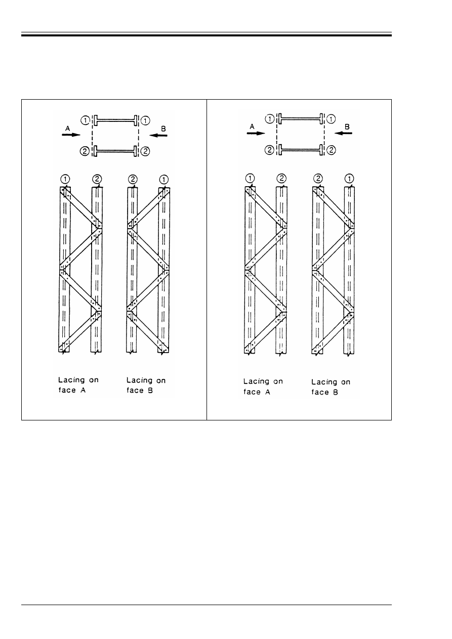
ENV 1993-1-1:1992
96
© BSI 04-2000
(a) Corresponding lacing systems
(Recommended system)
(b) Mutually opposed lacing systems
(Not recommended)
Figure 5.9.1 — Single lacing systems on opposite sides of main components
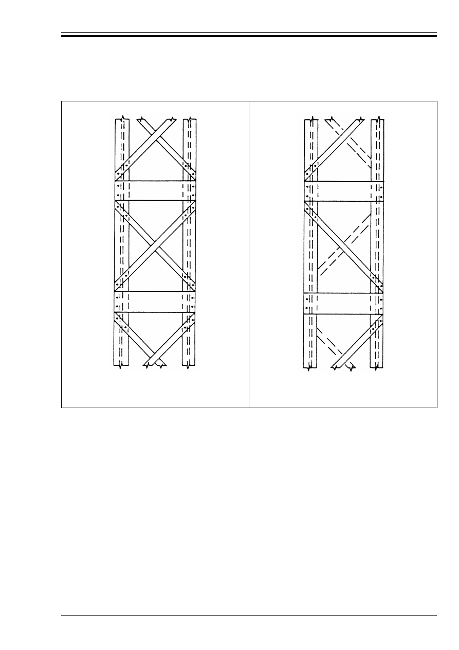
ENV 1993-1-1:1992
© BSI 04-2000
97
(a) Double intersection
lacing system
(b) Mutually opposed
lacing system
(not recommended)
Figure 5.9.2 — Lacing systems combined with other components perpendicular to the
longitudinal axis of the member
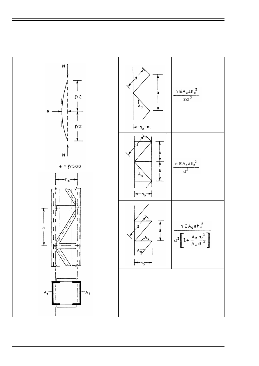
ENV 1993-1-1:1992
98
© BSI 04-2000
System
S
v
n is the number of planes of lacings.
A
d
and A
y
refer to a single plane.
Figure 5.9.3 — Laced compression member
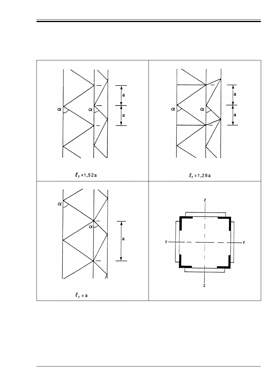
ENV 1993-1-1:1992
© BSI 04-2000
99
Figure 5.9.4 — Buckling lengths of angle chords in laced members
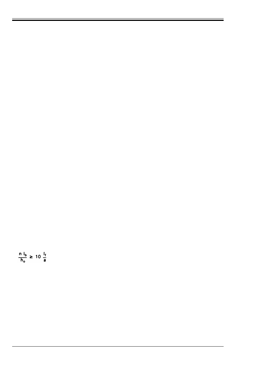
ENV 1993-1-1:1992
100
© BSI 04-2000
5.9.2.6 Lacing forces
(1) The lacing forces adjacent to the ends of the member should be derived from the internal shear force V
s
taken as:
5.9.3 Battened compression members
5.9.3.1 Application
(1) The design procedure given in this sub-clause is for a design compressive force N
Sd
applied to a
built-up member consisting of two similar parallel chords of uniform cross-section, spaced apart and
inter-connected by means of battens, which are rigidly connected to the chords and uniformly spaced
throughout the length of the member.
(2) The chords may be solid members or may themselves be laced or battened in the perpendicular plane.
(3) Where variations on the above are necessary the procedure should be supplemented or modified as
appropriate.
5.9.3.2 Constructional details
(1) Battens shall be supplied at each end of the member.
(2) Battens should also be supplied at intermediate points where loads are applied or lateral restraint is
supplied.
(3) Intermediate battens should be supplied to divide the length of the member into at least 3 panels. There
should be at least 3 panels between points which are taken as laterally restrained in the plane of the battens.
As far as possible, the intermediate battens should be spaced and proportioned uniformly throughout the
length of the member.
(4) Where parallel planes of battens are supplied, the battens in each plane should be arranged opposite each
other.
(5) When S
v
is evaluated disregarding the flexibility of the batten plates themselves [see 5.9.3.4(3)], the width
of an end batten along the length of the member should not be less than h
o
, and the width of an intermediate
batten should not be less than 0,5 h
o
, where h
o
is the distance between the centroids of the chords.
(6) Unless the flexibility of the batten plates is explicitly taken into account in the evaluation of S
v
, the battens
should also satisfy:
V
s
= Ï M
s
/=
(5.87)
with M
s
from 5.9.2.4
The force N
d
in a diagonal lacing is given by:
(5.88)
with d, n and h
0
from Figure 5.9.3.
(5.89)
where
l
b
is the in-plane second moment of area of one batten
l
f
is the in-plane second moment of area of one chord
h
o
is the distance between centroids of chords
a
is the system length between centrelines of battens
and
n
is the number of planes of battens.
N
d
V
s
d
nh
0
------------
=
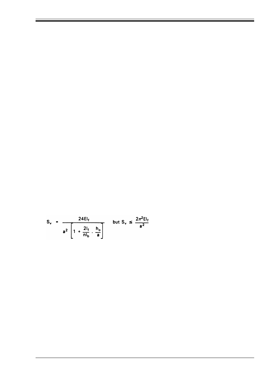
ENV 1993-1-1:1992
© BSI 04-2000
101
5.9.3.3 Second moment of area
(1) The effective in-plane second moment of area l
eff
of a battened compression member with two main
components should be taken as:
5.9.3.4 Chord forces at mid-length
(1) The chord force N
f.Sd
at mid-length should be determined from:
(2) Provided that the criterion in 5.9.3.2(6) is satisfied, the shear stiffness S
v
should be taken as:
(3) When the criterion in 5.9.3.2(6) is not satisfied, the flexibility of the batten plates should be taken into
account by obtaining S
v
from:
5.9.3.5 Buckling resistance of chords
(1) The buckling length of a chord in the plane of the battens should be taken as the system length a between
centrelines of battens.
5.9.3.6 Moments and shears due to battening
(1) The battens, their connections to the chords and the chords themselves should be checked for the moments
and forces in the end panel indicated in Figure 5.9.5, in which the internal shear force V
s
is taken as:
(2) For the purpose of this check, the axial force in each chord may be taken as 0,5N
Sd
even when there are
only three panels in the length of the member.
(3) In the case of chords with unsymmetric cross-sections (such as channels) the reduced plastic resistance
moments for use in the expression given in 5.4.8.1(11) may be taken as the mean of the values for positive
and negative bending moments for the purpose of this check.
l
eff
= 0,5h
o
2
A
f
+ 2Èl
f
(5.90)
with È obtained from the following:
Æ
k 75:
È = 1
75 < Æ < 150:
È = 2 – Æ/75
Æ
U 150:
È = 0
in which Æ = =/i
o
where A
f
is the cross-sectional area of one chord
l
f
is the second moment of area of one chord
h
o
is the distance between centroids of chords
i
o
= [0,5 l
1
/A
f
]
0,5
and
l
f
is the value of l
eff
with È = 1
N
f.Sd
= 0,5(N
Sd
+ M
s
h
o
A
f
/l
eff
)
(5.91)
where
M
s
= N
Sd
e
o
/(1 – N
Sd
/N
cr
– N
Sd
/S
v
)
e
o
= =/500 (see 5.9.1)
N
cr
= Ï
2
El
eff
eff
/=
2
S
v
= 2Ï
2
El
eff
f
/a
2
(5.92)
(5.93)
V
s
= Ï M
s
s
/=
(5.94)
with M
s
from 5.9.3.4.

ENV 1993-1-1:1992
102
© BSI 04-2000
5.9.4 Closely spaced built-up members
(1) Built-up compression members such as those shown in Figure 5.9.6, with main components in contact or
closely spaced and connected through packing plates, need not be treated as battened members provided that
they are connected together by bolts or welds at a spacing of not more than 15 i
min
, where i
min
is the minimum
radius of gyration of a main component.
(2) The interconnecting bolts or welds should be designed to transmit the longitudinal shear between the
main components derived from the internal shear force V
s
.
(3) V
s
may be taken as 2,5 % of the axial force in the member. Alternatively V
s
may be determined as
in 5.9.3.6.
(4) The longitudinal shear per interconnection may be taken as 0,25V
s
a/i
min
where a is the system length of
the main components centre-to-centre of interconnections.
5.9.5 Star-battened angle members
(1) Built-up compression members consisting of two similar angle members connected by pairs of battens in
two perpendicular planes as shown in Figure 5.9.7, may be checked for buckling about the y-y axis as a single
integral member, provided that the buckling lengths in the two perpendicular planes y-y and z-z are equal
and provided that the spacing of pairs of battens is not more than 70 i
min
where i
min
is the minimum radius
of gyration of one angle.
(2) In the case of unequal-leg angles it may be assumed that:
where i
o
is the minimum radius of gyration of the built-up member.
i
y
= i
o
/1,15
(5.95)
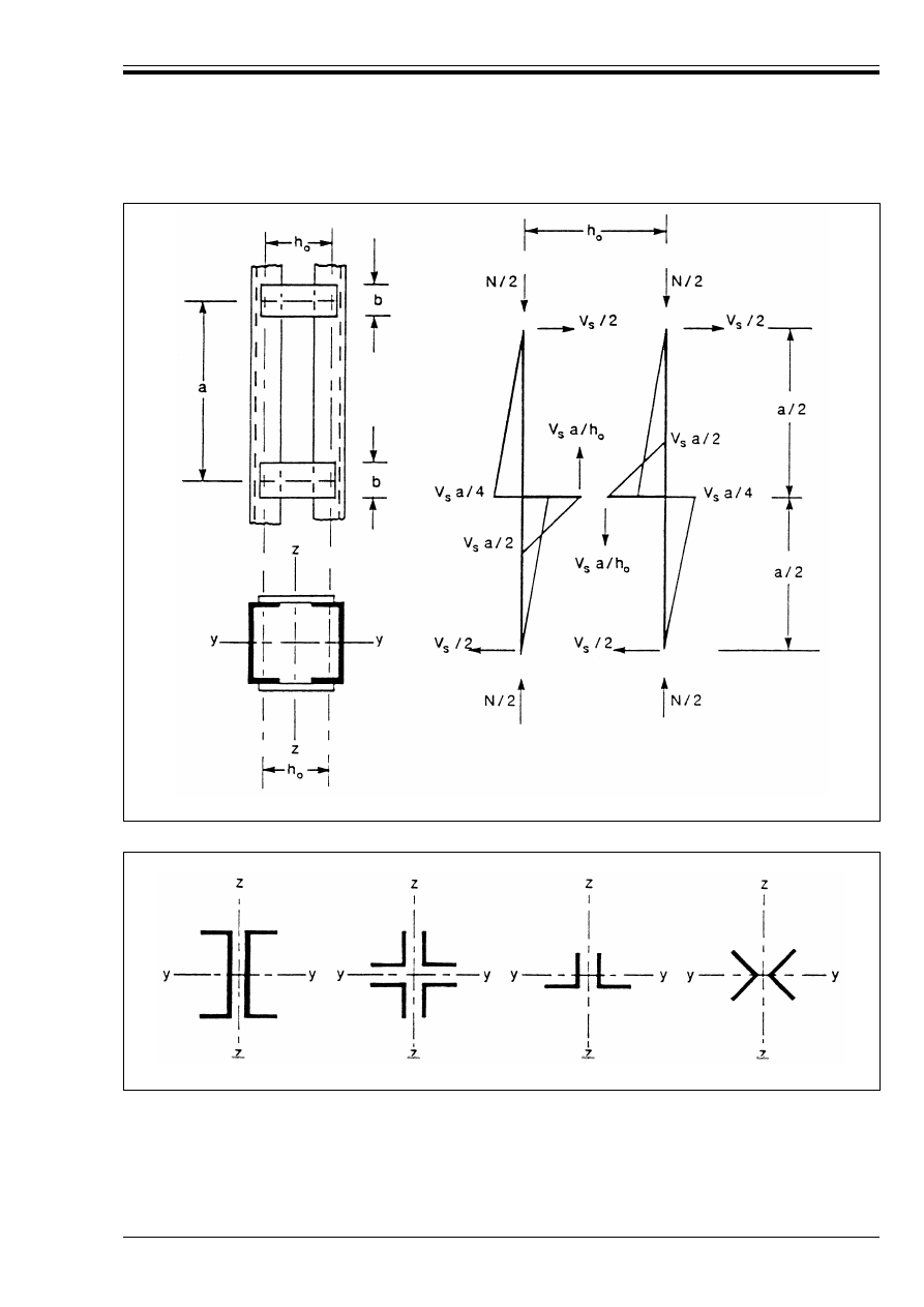
ENV 1993-1-1:1992
© BSI 04-2000
103
Figure 5.9.5 — Battened compression member
Figure 5.9.6 — Closely spaced built-up members
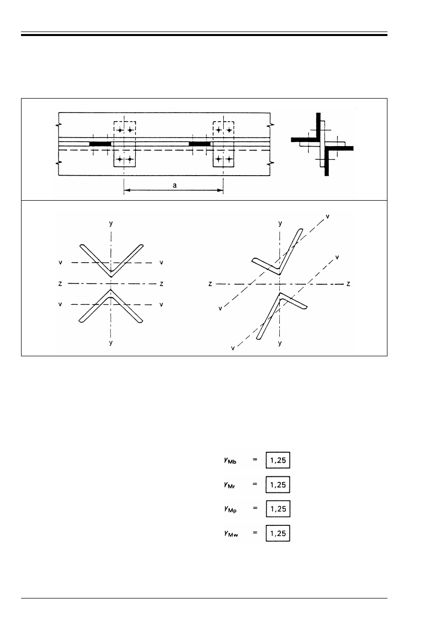
ENV 1993-1-1:1992
104
© BSI 04-2000
6 Connections subject to static loading
6.1 Basis
6.1.1 Introduction
(1) All connections shall have a design resistance such that the structure remains effective and is capable
of satisfying all the basic design requirements given in Chapter 2.
(2) The partial safety factor ¾
M
shall be taken as follows:
(3) Connections subject to fatigue shall also satisfy the requirements given in Chapter 9.
Figure 5.9.7 — Star-battened angle members
w
resistance of bolted connections:
w
resistance of rivetted connections:
w
resistance of pin connections:
w
resistance of welded connections:
w
slip resistance:
see 6.5.8.1
w
resistance of joints in hollow section lattice girders:
see Annex K
w
resistance of members and cross-sections:
¾
M0
, ¾
M1
and ¾
M2
see 5.1.1

ENV 1993-1-1:1992
© BSI 04-2000
105
6.1.2 Applied forces and moments
(1) The forces and moments applied to connections at the ultimate limit state shall be determined by global
analysis conforming with Chapter 5.
(2) These applied forces and moments shall include:
• second order effects;
• the effects of imperfections, see 5.2.4;
• the effects of connection flexibility in the case of semi-rigid connections, see 6.9.
6.1.3 Resistance of connections
(1) The resistance of a connection shall be determined on the basis of the resistances of the individual
fasteners or welds.
(2) Linear-elastic analysis shall generally be used in the design of the connection. Alternatively
non-linear analysis of the connection may be employed provided that it takes account of the load
deformation characteristics of all the components of the connection.
(3) If the design model is based on yield lines, the adequacy of this model shall be demonstrated on the basis
of physical tests.
6.1.4 Design assumptions
(1) Connections may be designed by distributing the internal forces and moments in whatever rational way
is best, provided that:
a) the assumed internal forces and moments are in equilibrium with the applied forces and moments,
b) each element in the connection is capable of resisting the forces or stresses assumed in the analysis,
c) the deformations implied by this distribution are within the deformation capacity of the fasteners or
welds and of the connected parts, and
d) the deformations assumed in any design model based on yield lines are based on rigid body rotations
(and in-plane deformations) which are physically possible.
(2) In addition, the assumed distribution of internal forces shall be realistic with regard to relative
stiffnesses within the joint. The internal forces will seek to follow the path with the greatest rigidity. This
path shall be clearly identified and consistently followed throughout the design of the connection.
(3) Residual stresses and stresses due to tightening of fasteners and due to ordinary accuracy of fit-up need
not normally be allowed for.
6.1.5 Fabrication and erection
(1) Ease of fabrication and erection shall be considered in the design of all joints and splices.
(2) Attention should be paid to:
• the clearances necessary for safe erection,
• the clearances needed for tightening fasteners,
• the need for access for welding,
• the requirements of welding procedures, and
• the effects of angular and length tolerances on fit-up.
(3) Attention should also be paid to the requirements for:
• subsequent inspection,
• surface treatment, and
• maintenance.
NOTE For detailed rules on fabrication and erection see Chapter 7.
6.2 Intersections
(1) Members meeting at a joint shall normally be arranged with their centroidal axes intersecting at a
point.
(2) Where there is eccentricity at intersections this shall be taken into account, except in the case of
particular types of structures where it has been demonstrated that it is not necessary.

ENV 1993-1-1:1992
106
© BSI 04-2000
(3) In the case of joints with angles or tees connected by at least two bolts at each connection, the setting
out lines for the bolts in the angles and tees may be substituted for the centroidal axes for the purpose of
intersection at the joints.
6.3 Joints loaded in shear subject to vibration and/or load reversal
(1) Where a joint loaded in shear is subject to impact or significant vibration, either welding or else bolts
with locking devices, preloaded bolts, injection bolts or other types of bolt which effectively prevent
movement shall be used.
(2) Where slipping is not acceptable in a joint because it is subject to reversal of shear load (or for any other
reason), either preloaded bolts in a slip-resistant connection (Category B or C as appropriate, see 6.5.3),
fitted bolts or welding shall be used.
(3) For wind and/or stability bracings, bolts in bearing type connections (Category A in 6.5.3) may normally
be used.
6.4 Classification of connections
6.4.1 General
(1) The structural properties of all connections shall be such as to achieve the assumptions made in the
analysis of the structure and in the design of the members.
(2) Connections may be classified:
• by rigidity, see 6.4.2.
• by strength, see 6.4.3.
(3) The types of connections should conform with Table 5.2.1 depending on the member design assumptions
and the method of global analysis, see 5.2.2.
6.4.2 Classification by rigidity
6.4.2.1 Nominally pinned connections
(1 )A nominally pinned connection shall be so designed that it cannot develop significant moments which
might adversely affect members of the structure.
(2) Nominally pinned connections should be capable of transmitting the forces calculated in design and
should be capable of accepting the resulting rotations.
6.4.2.2 Rigid connections
(1) A rigid connection shall be so designed that its deformation has no significant influence on the
distribution of internal forces and moments in the structure, nor on its overall deformation.
(2) The deformations of rigid connections should be such that they do not reduce the resistance of the
structure by more than 5 %.
(3) Rigid connections should be capable of transmitting the forces and moments calculated in design.
6.4.2.3 Semi-rigid connections
(1) A connection which does not meet the criteria for a rigid connection or a nominally pinned connection
given in 6.4.2.2(1) and 6.4.2.1(1) shall be classified as a semi-rigid connection.
(2) Semi-rigid connections should provide a predictable degree of interaction between members, based on the
design moment-rotation characteristics of the joints.
(3) Semi-rigid connections should be capable of transmitting the forces and moments calculated in design.
6.4.3 Classification by strength
6.4.3.1 Nominally pinned connections
(1) A nominally pinned connection shall be capable of transmitting the calculated design forces, without
developing significant moments which might adversely affect members of the structure.
(2) The rotation capacity of a nominally pinned connection should be sufficient to enable all the necessary
plastic hinges to develop under the design loads.

ENV 1993-1-1:1992
© BSI 04-2000
107
6.4.3.2 Full-strength connections
(1) The design resistance of a full strength connection shall be not less than that of the member connected.
(2) Where the rotation capacity of a full-strength connection is limited, overstrength effects should be taken
into account. If the design resistance of the connection is at least 1,2 times the design plastic resistance of the
member, the rotation capacity of the connection need not be checked.
(3) The rigidity of a full-strength connection should be such that, under the design loads, the rotations at the
necessary plastic hinges do not exceed their rotation capacities.
6.4.3.3 Partial-strength connections
(1) The design resistance of a partial-strength connection shall not be less than that necessary to transmit
the calculated design forces and moments, but may be less than that of the member connected.
(2) The rotation capacity of a partial-strength connection which occurs at a plastic hinge location shall not
be less than that needed to enable all the necessary plastic hinges to develop under the design loads.
(3) The rotation capacity of a connection may be demonstrated by experimental evidence. Experimental
demonstration is not required when using details which experience has proved have adequate properties.
(4) The rigidity of a partial-strength connection should be such that the rotation capacity of none of the
necessary plastic hinges is exceeded under the design loads.
6.5 Connections made with bolts, rivets or pins
6.5.1 Positioning of holes for bolts and rivets
6.5.1.1 Basis
(1) The positioning of holes for bolts and rivets shall be such as to prevent corrosion and local buckling and
to facilitate the installation of the bolts or rivets.
(2) The positioning of the holes shall also be in conformity with the limits of validity of the rules used to
determine the design resistances of the bolts and rivets.
6.5.1.2 Minimum end distance
(1) The end distance e
1
from the centre of a fastener hole to the adjacent end of any part, measured in the
direction of load transfer (see Figure 6.5.1), should be not less than 1,2d
o
, where d
o
is the hole diameter,
see 7.5.2.
(2) The end distance should be increased if necessary to provide adequate bearing resistance, see 6.5.5
and 6.5.6.
6.5.1.3 Minimum edge distance
(1) The edge distance e
2
from the centre of a fastener hole to the adjacent edge of any part, measured at right
angles to the direction of load transfer (see Figure 6.5.1), should normally be not less than 1,5d
o
.
(2) The edge distance may be reduced to not less than 1,2d
o
provided that the design bearing resistance is
reduced accordingly, see 6.5.5 and 6.5.6.
6.5.1.4 Maximum end and edge distances
(1) Where the members are exposed to the weather or other corrosive influences, the maximum end or edge
distance should not exceed 40 mm + 4t, where t is the thickness of the thinner outer connected part.
(2) In other cases the end or edge distance should not exceed 12t or 150 mm, whichever is the larger.
The edge distance should also not exceed the maximum to satisfy local buckling requirements for an
outstand element. This requirement does not apply to fasteners interconnecting the components of tension
members. The end distance is not affected by this requirement.
6.5.1.5 Minimum spacing
(1) The spacing p
1
between centres of fasteners in the direction of load transfer (see Figure 6.5.1), should be
not less than 2,2d
o
. This spacing should be increased if necessary to provide adequate bearing resistance,
see 6.5.5 and 6.5.6.
(2) The spacing p
2
between rows of fasteners, measured perpendicular to the direction of load transfer
(see Figure 6.5.1), should normally be not less than 3,0d
o
. This spacing may be reduced to 2,4d
o
provided
that the design bearing resistance is reduced accordingly, see 6.5.5 and 6.5.6.
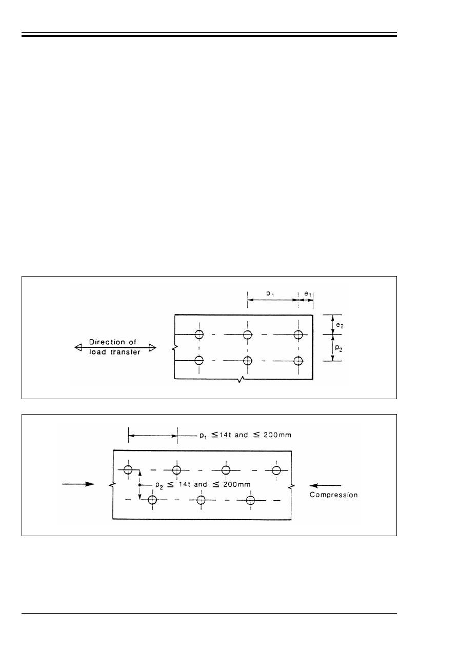
ENV 1993-1-1:1992
108
© BSI 04-2000
6.5.1.6 Maximum spacing in compression members
(1) The spacing p
1
of the fasteners in each row and the spacing p
2
between rows of fasteners, should not exceed
the lesser of 14t or 200 mm. Adjacent rows of fasteners may be symmetrically staggered,
see Figure 6.5.2.
(2) The centre-to-centre spacing of fasteners should also not exceed the maximum width which satisfies local
buckling requirements for an internal element, see 5.3.4.
6.5.1.7 Maximum spacing in tension members
(1) In tension members the centre-to-centre spacing p
1,i
of fasteners in inner rows may be twice that given
in 6.5.1.6(1) for compression members, provided that the spacing p
1,o
in the outer row along each edge does
not exceed that given in 6.5.1.6(1), see Figure 6.5.3.
(2) Both of these values may be multiplied by 1,5 in members not exposed to the weather or other corrosive
influences.
6.5.1.8 Slotted holes
(1) The minimum distance e
3
from the axis of a slotted hole to the adjacent end or edge of any part
(see Figure 6.5.4) should not be less than 1,5d
o
.
(2) The minimum distance e
4
from the centre of the end radius of a slotted hole to the adjacent end or edge
of any part (see Figure 6.5.4) should not be less than 1,5d
o
.
Figure 6.5.1 — Symbols for spacing of fasteners
Figure 6.5.2 — Staggered spacing — compression
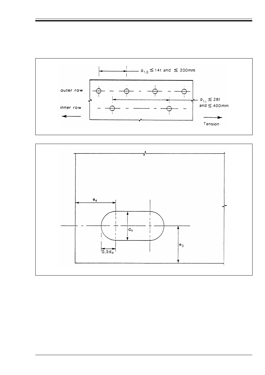
ENV 1993-1-1:1992
© BSI 04-2000
109
6.5.2 Deductions for fastener holes
6.5.2.1 General
(1) In the design of connections in compression members, no deduction for fastener holes is normally
required except for oversize or slotted holes.
(2) In the design of connections in other types of member the provisions given in 5.4.3, 5.4.5.3(3)
and 5.4.6(8) apply for tension, bending moment and shear force respectively.
6.5.2.2 Design shear rupture resistance
(1) “Block shear” failure at a group of fastener holes near the end of a beam web or a bracket,
see Figure 6.5.5, shall be prevented by using appropriate hole spacing. This mode of failure generally
consists of tensile rupture along the line of fastener holes on the tension face of the hole group, accompanied
by gross section yielding in shear at the row of fastener holes along the shear face of the hole group,
see Figure 6.5.5.
Figure 6.5.3 — Spacing in tension members
Figure 6.5.4 — End and edge distances for slotted holes

ENV 1993-1-1:1992
110
© BSI 04-2000
(2) The design value of the effective resistance to block shear V
eff.Rd
should be determined from:
(3) The effective shear area A
v.eff
should be determined as follows:
V
eff.Rd
= (f
Y
/Æ3) A
v.eff
/¾
M0
(6.1)
where A
v.eff
is the effective shear area
A
v.eff
= t L
v.eff
where
L
v.eff
= L
v
+ L
1
+ L
2
but L
v.eff
k L
3
in which L
1
= a
1
but L
1
k 5 d
L
2
= (a
2
– k d
o.t
) (f
u
/f
y
)
and
L
3
= L
v
+ a
1
+ a
3
but L
3
< (L
v
+ a
1
+ a
3
– nd
o.v
) (f
u
/f
y
)
where a
1
, a
2
, a
3
and L
v
are as indicated in Figure 6.5.5
d
is the nominal diameter of the fasteners
d
o.t
is the hole size for the tension face, generally the hole diameter, but for horizontally
slotted holes the slot length should be used
d
o.v
is the hole size for the shear face, generally the hole diameter, but for vertically slotted
holes the slot length should be used
n
is the number of fastener holes on the shear face
t
is the thickness of the web or bracket
and k is a coefficient with values as follows:
w
for a single row of bolts: k = 0,5
w
for two rows of bolts:
k = 2,5
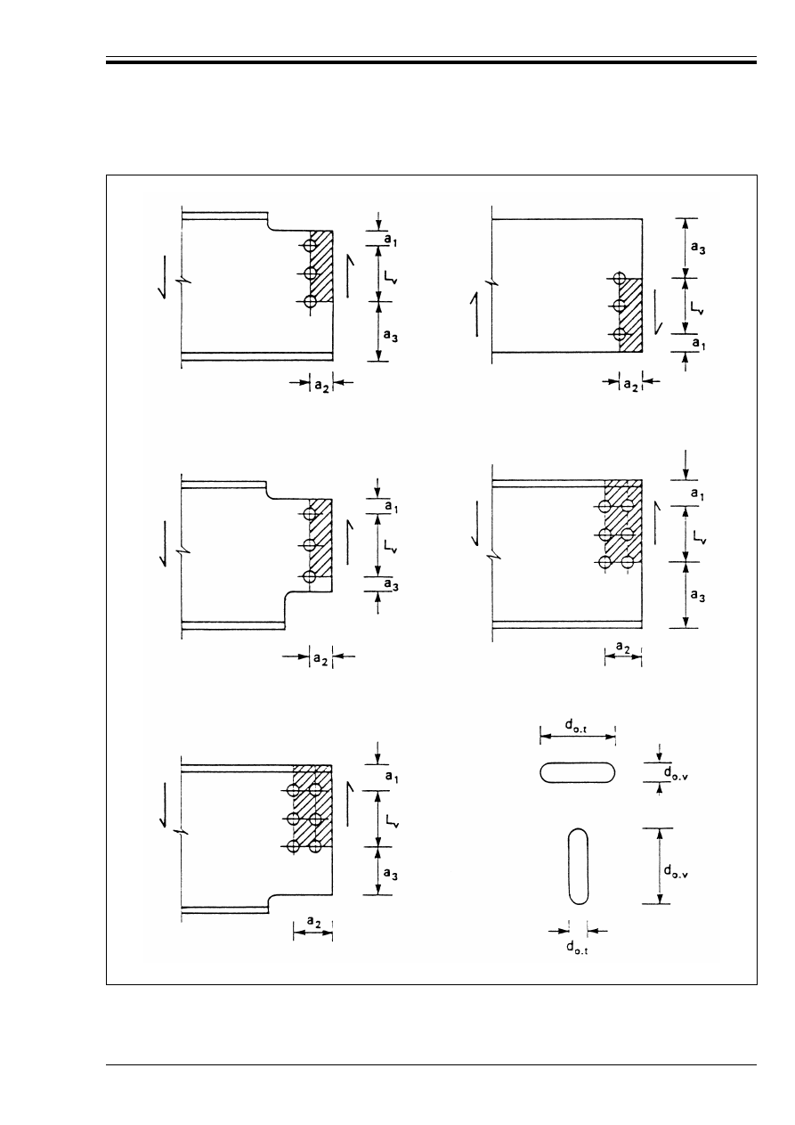
ENV 1993-1-1:1992
© BSI 04-2000
111
Figure 6.5.5 — Block shear — effective shear area
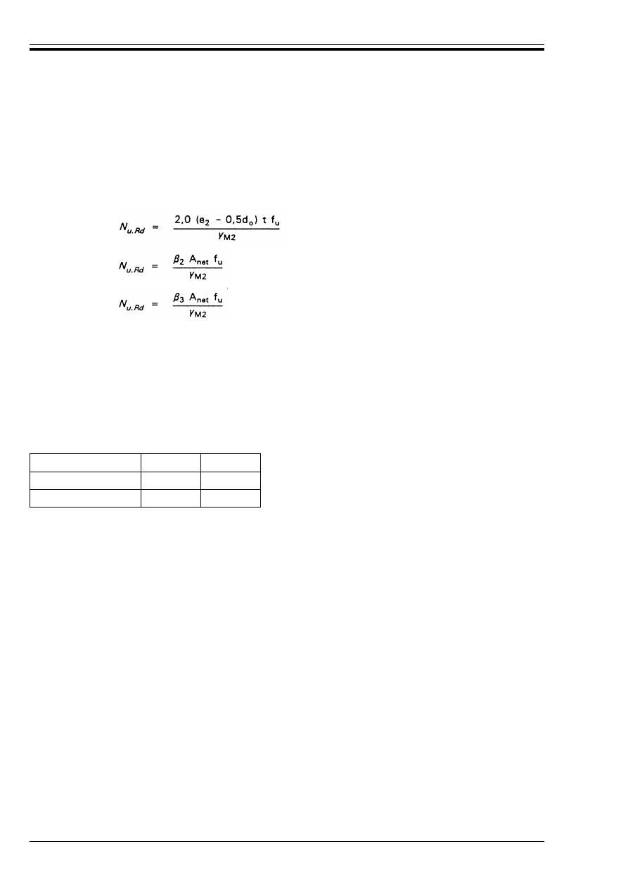
ENV 1993-1-1:1992
112
© BSI 04-2000
6.5.2.3 Angles connected by one leg
(1) In the case of unsymmetrical or unsymmetrically connected members such as angles connected by one
leg, the eccentricity of fasteners in end connections and the effects of the spacing and edge distances of the
bolts shall be taken into account when determining the design resistance.
(2) Angles connected by a single row of bolts in one leg, see Figure 6.5.6, may be treated as concentrically
loaded and the design ultimate resistance of the net section determined as follows:
(3) The design buckling resistance of a compression member, see 5.5.1, should be based on the gross
cross-sectional area, but should not be taken as more than the design resistance of the cross-section given
in (2).
Table 6.5.1 — Reduction factors 
2
and 
3
with 1 bolt:
(6.2)
with 2 bolts:
(6.3)
with 3 bolts:
(6.4)
where 
2
and 
3
are reduction factors dependent on the pitch p
1
as given in Table 6.5.1.
For intermediate values of p
1
the value of ¶ may be determined by linear interpolation.
and
A
net
is the net area of the angle. For an unequal-leg angle connected by its smaller leg, A
net
should
be taken as equal to the net section area of an equivalent equal-leg angle of leg size equal to that of
the smaller leg.
Pitch
p
1
k 2,5 d
o
U 5,0 d
o
2 bolts
2
0,4
0,7
3 bolts or more
3
0,5
0,7
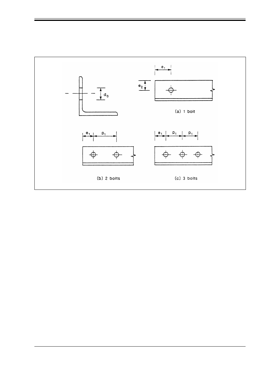
ENV 1993-1-1:1992
© BSI 04-2000
113
6.5.3 Categories of bolted connections
6.5.3.1 Shear connections
(1) The design of a bolted connection loaded in shear shall conform with one of the following categories,
see Table 6.5.2.
(2) Category A: Bearing type
In this category ordinary bolts (manufactured from low carbon steel) or high strength bolts, from grade 4.6
up to and including grade 10.9, shall be used. No preloading and special provisions for contact surfaces are
required. The design ultimate shear load shall not exceed the design shear resistance nor the design
bearing resistance, obtained from 6.5.5.
(3) Category B: Slip-resistant at serviceability limit state
In this category preloaded high strength bolts with controlled tightening in conformity with Reference
Standard 8 shall be used. Slip shall not occur at the serviceability limit state. The combination of actions
to be considered shall be selected from 2.3.4 depending on the load cases where resistance to slip is
required. The design serviceability shear load should not exceed the design slip resistance, obtained
from 6.5.8. The design ultimate shear load shall not exceed the design shear resistance nor the design
bearing resistance, obtained from 6.5.5.
(4) Category C: Slip-resistant at ultimate limit state
In this category preloaded high strength bolts with controlled tightening in conformity with Reference
Standard 8 shall be used. Slip shall not occur at the ultimate limit state. The design ultimate shear load
shall not exceed the design slip resistance obtained from 6.5.8 nor the design bearing resistance obtained
from 6.5.5.
In addition, at the ultimate limit state the design plastic resistance of the net section at bolt holes
N
net.Rd
(see 5.4.3) shall be taken as:
Figure 6.5.6 — Connections of angles
N
net.Rd
= A
net
f
y
/¾
M0
(5.14)

ENV 1993-1-1:1992
114
© BSI 04-2000
Table 6.5.2 — Categories of bolted connections
6.5.3.2 Tension connections
(1) The design of a bolted connection loaded in tension shall conform with one of the following categories,
see Table 6.5.2.
(2) Category D: Connections with non-preloaded bolts
In this category ordinary bolts (manufactured from low carbon steel) or high strength bolts up to and
including grade 10.9 shall be used. No preloading is required. This category shall not be used where the
connections are frequently subjected to variations of tensile loading. However, they may be used in
connections designed to resist normal wind loads.
(3) Category E: Connections with preloaded high strength bolts
In this category preloaded high strength bolts with controlled tightening in conformity with Reference
Standard 8 shall be used. Such preloading improves fatigue resistance. However, the extent of the
improvement depends on detailing and tolerances.
(4) For tension connections of both Categories D and E no special treatment of contact surfaces is necessary,
except where connections of Category E are subject to both tension and shear
(combination E-B or E-C).
6.5.4 Distribution of forces between fasteners
(1) The distribution of internal forces between fasteners at the ultimate limit state shall be proportional to
the distance from the centre of rotation, see Figure 6.5.7(a), in the following cases:
• Category C slip-resistant connections
• Other shear connections where the design shear resistance F
v.Rd
of a fastener is less than the design
bearing resistance F
b.Rd
.
(2) In other cases the distribution of internal forces between fasteners at the ultimate limit state may be either
as in (1) or else plastic, see Figure 6.5.7. Any reasonable distribution may be assumed provided that it
satisfies the requirements given in 6.1.4.
(3) In a lap joint, the same bearing resistance in any particular direction should be assumed for each
fastener.
Shear connections
Category
Criteria
Remarks
A
bearing type
F
v.Sd
F
v.Sd
k F
v.Rd
k F
b.Rd
No preloading required.
All grades from 4.6 to 10.9.
B
slip-resistant at serviceability
F
v.Sd.ser
F
v.sd
F
v.sd
k F
s.Rd.ser
k F
v.Rd
k F
b.Rd
Preloaded high strength bolts.
No slip at the serviceability limit state.
C
slip-resistant at ultimate
F
v.Sd
F
v.Sd
k F
s.Rd
k F
b.Rd
Preloaded high strength bolts.
No slip at the ultimate limit state.
Tension capacity
Category
Creterion
Remarks
D
non-preloaded
F
t.Sd
k F
t.Rd
No preloading required.
All grades from 4.6 to 10.9.
E
preloaded
F
t.Sd
k F
t.Rd
Preloaded high strength bolts.
Key:
F
v.Sd.ser
F
v.Sd
F
v.Rd
F
b.Rd
F
s.Rd.ser
F
s.Rd
F
t.sd
F
t.Rd
=
=
=
=
=
=
=
=
design shear force per bolt for the serviceability limit state
design shear force per bolt for the ultimate limit state
design shear resistance per bolt
design bearing resistance per bolt
design slip resistance per bolt at the serviceability limit state
design slip resistance per bolt at the ultimate limit state
design tensile force per bolt for the ultimate limit state
design tension resistance per bolt
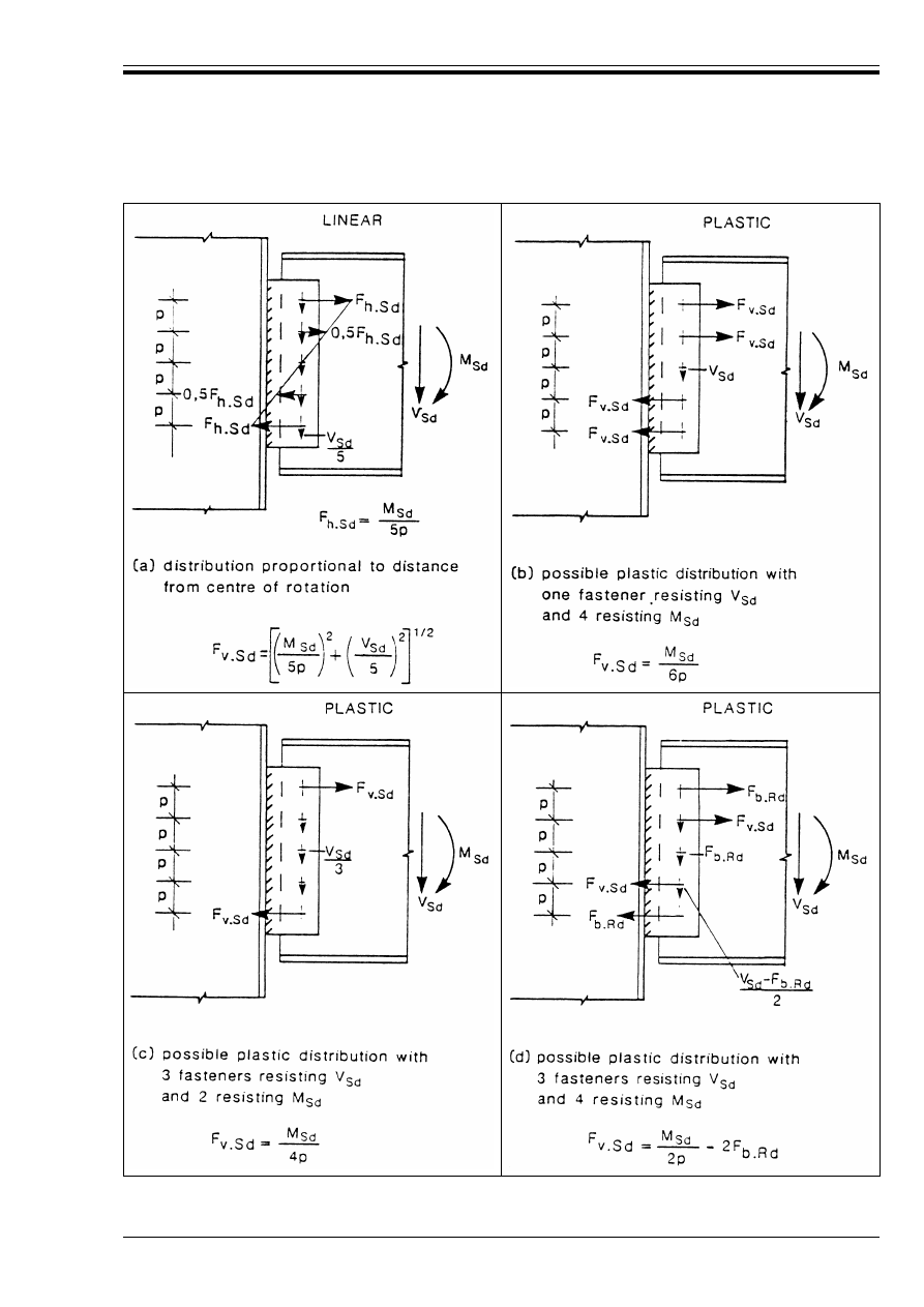
ENV 1993-1-1:1992
© BSI 04-2000
115
Figure 6.5.7 — Distribution of loads between fasteners
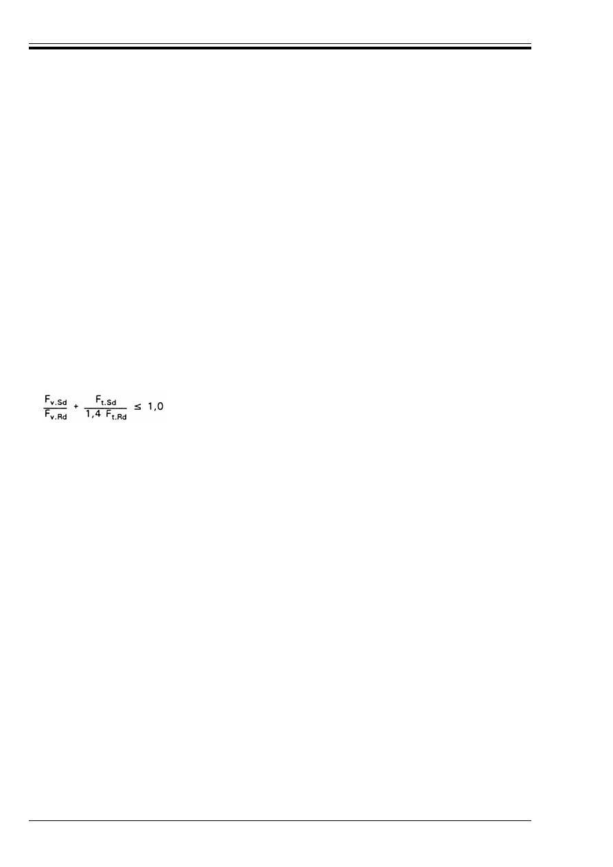
ENV 1993-1-1:1992
116
© BSI 04-2000
6.5.5 Design resistances of bolts
(1) The design resistances given in this clause apply to standard manufactured bolts of strength grades
from grade 4.6 up to and including grade 10.9, which conform with Reference Standard 3,
see normative Annex B. Nuts and washers shall also conform with Reference Standard 3 and shall have
the corresponding specified strengths.
(2) At the ultimate limit state the design shear force F
v.Sd
on a bolt shall not exceed the lesser of:
• the design shear resistance F
v.Rd
• the design bearing resistance F
b.Rd
both as given in Table 6.5.3.
(3) The design tensile force F
t.Sd
, inclusive of any force due to prying action, shall not exceed the design
tension resistance B
t.Rd
of the bolt-plate assembly.
(4) The design tension resistance of the bolt-plate assembly B
t.Rd
shall be taken as the smaller of the design
tension resistance F
t.Rd
given in Table 6.5.3 and the design punching shear resistance of the bolt head and
the nut, B
p.Rd
obtained from:
(5) Bolts subject to both shear force and tensile force shall in addition satisfy the following:
(6) The design resistances for tension and for shear through the threaded portion given in Table 6.5.3 are
restricted to bolts manufactured in conformity with Reference Standard 3. For other items with cut
threads, such as holding-down bolts or tie rods fabricated from round steel bars where the threads are cut
by the steelwork fabricator and not by a specialist bolt manufacturer, the relevant values from
Table 6.5.3 shall be reduced by multiplying them by a factor of 0,85.
(7) The values for design shear resistance F
v.Rd
given in Table 6.5.3 apply only where the bolts are used in
holes with nominal clearances not exceeding those for standard holes as specified in 7.5.2(1).
(8) M12 and M14 bolts may also be used in 2 mm clearance holes provided that:
• for bolts of strength grade 4.8, 5.8, 6.8 or 10.9 the design shear resistance F
v.Rd
is taken as 0,85 times
the value given in Table 6.5.3.
• the design shear resistance F
v.Rd
(reduced as above if applicable) is not less than the design bearing
resistance F
b.Rd
.
(9) The values for the design bearing resistance in Table 6.5.3 apply only where the edge distance e
2
is not
less than 1,5 d
o
and the spacing p
2
measured transverse to the load direction is at least 3,0 d
o
.
(10) If e
2
is reduced to 1,2 d
o
and/or p
2
is reduced to 2,4 d
o
, then the bearing resistance F
b.Rd
should be
reduced to 2/3 of the value given in Table 6.5.3. For intermediate values 1,2 d
o
< e
2
k 1,5 d
o
and/or 2,4 d
o
k p
2
k 3d
o
the value of F
b.Rd
may be determined by linear interpolation.
(11) For bolts in standard clearance holes (see 7.5.2), conservative values of the design bearing resistance
F
b.Rd
, based on the bolt diameter d, may be obtained from Table 6.5.4.
B
p.Rd
= 0,6 Ï d
m
t
p
f
u
/¾
Mb
(6.5)
where t
p
is the thickness of the plate under the bolt head or the nut
and
d
m
is the mean of the across points and across flats dimensions of the bolt head or the nut,
whichever is smaller
(6.6)
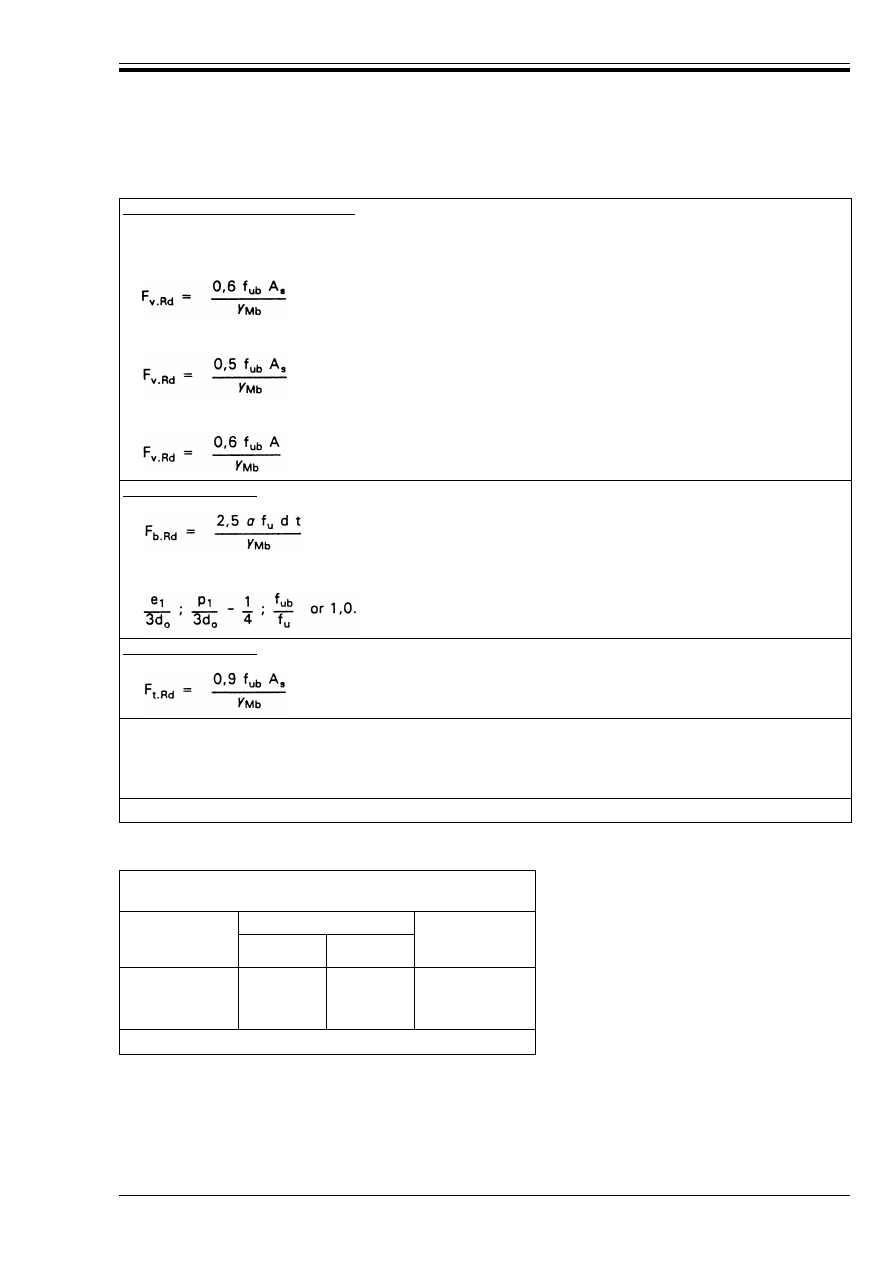
ENV 1993-1-1:1992
© BSI 04-2000
117
Table 6.5.3 — Design resistance for bolts
Table 6.5.4 — Design bearing resistance —
based on bolt diameter
6.5.6 Design resistance of rivets
(1) At the ultimate limit state the design shear force F
v.Sd
on a rivet shall not exceed the lesser of:
• the design shear resistance F
v.Rd
• the design bearing resistance F
b.Rd
both as given in Table 6.5.5.
Shear resistance per shear plane:
if the shear plane passes through the threaded portion of the bolt:
w
for strength grades 4.6, 5.6 and 8.8:
w
for strength grades 4.8, 5.8, and 10.9:
if the shear plane passes through the unthreaded portion of the bolt:
Bearing resistance:
where µ is the smallest of:
Tension resistance:
A is the gross cross-section area of bolt
A
s
is the tensile stress area of bolt
d is the bolt diameter
d
o
is the hole diameter
See also
Table 6.5.4
for values of design bearing resistance based on bolt diameter.
Conservative values for bolts in standard clearance
holes (see 7.5.2) with ¾
Mb
= 1,25
Nominal bearing
class
Minimum dimensions
Design bearing
resistance
F
b.Rd
e
1
p
1
low
medium
high
1,7d
2,5d
3,4d
2,5d
3,4d
4,3d
1,0 f
u
dt
aa
1,5 f
u
dt
aa
2,0 f
u
dt
aa
a
but F
b.Rd
k 2,0 f
ub
dt
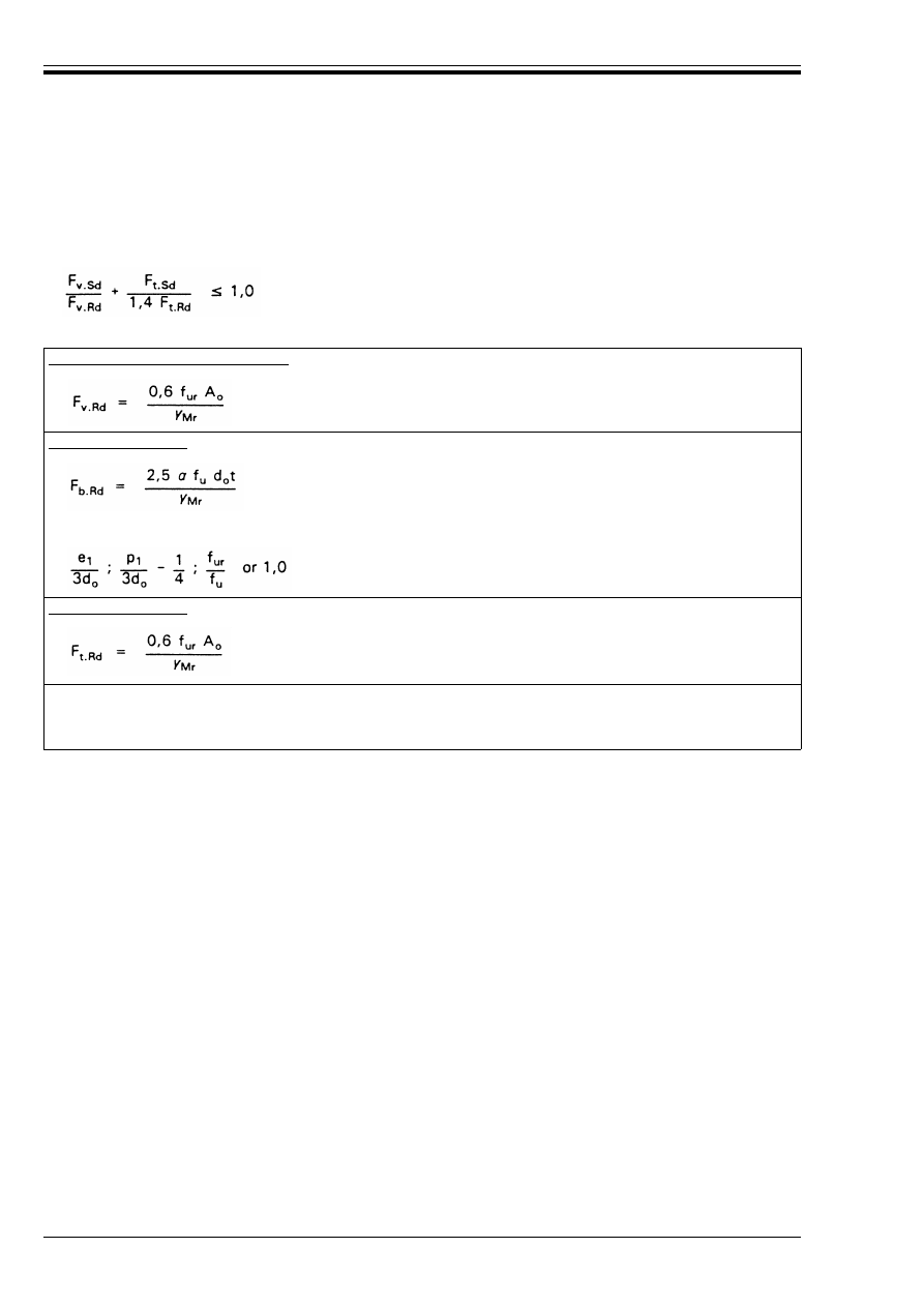
ENV 1993-1-1:1992
118
© BSI 04-2000
(2) Riveted connections shall be designed to transfer forces essentially in shear. If tension is necessary to
satisfy equilibrium, the design tensile force F
t.Sd
shall not exceed the design tension resistance F
t.Rd
given
in Table 6.5.5.
(3) Rivets subject to both shear and tensile forces shall in addition satisfy the following:
Table 6.5.5 — Design resistances for rivets
(4) The values for the design bearing resistance F
b.Rd
in Table 6.5.5 apply only where the edge distance e
2
is not less than 1,5 d
o
and the spacing p
2
measured transverse to the load direction is at least 3,0 d
o
.
(5) For smaller values of e
2
and/or p
2
the same reduction of F
b.Rd
should be applied as given in 6.5.5(10) for
bolts.
(6) For grade Fe 360 the “as driven” value of f
ur
may be taken as 400 N/mm
2
.
(7) As a general rule, the grip length of a rivet should not exceed 4,5d for hammer riveting and 6,5d for press
riveting.
6.5.7 Countersunk bolts and rivets
(1) The design tension resistance F
t.Rd
of a countersunk bolt or rivet shall be taken as 0,7 times the design
tension resistance given in Table 6.5.3 or Table 6.5.5 respectively.
(2) The angle and depth of countersinking shall conform with Reference Standard 3, otherwise the tension
resistance shall be adjusted accordingly.
(3) The design bearing resistance F
b.Rd
of a countersunk bolt or rivet shall be calculated as specified in 6.5.5
or 6.5.6 respectively, with half the depth of the countersink deducted from the thickness t of the relevant
part joined.
(6.6)
Shear resistance per shear plane:
Bearing resistance:
where µ is the smallest of:
Tension resistance:
A
o
is the area of the rivet hole
d
o
is the diameter of the rivet hole
f
ur
is the specified ultimate tensile strength of the rivet.
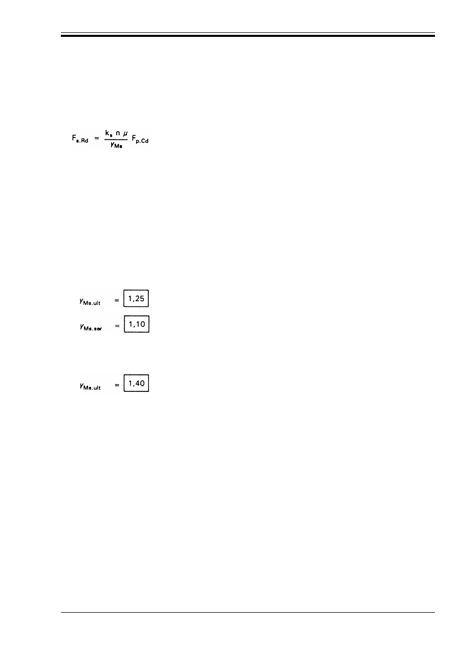
ENV 1993-1-1:1992
© BSI 04-2000
119
6.5.8 High strength bolts in slip-resistant connections
6.5.8.1 Slip resistance
(1) The design slip resistance of a preloaded high-strength bolt shall be taken as:
(2) The value of k
s
shall be taken as follows:
• where the holes in all the plies have standard nominal clearances as specified in 7.5.2(1):
k
s
= 1,0
• for oversize holes, as specified in 7.5.2(6), or short slotted holes, as specified in 7.5.2(9):
k
s
= 0,85
• for long slotted holes, as specified in 7.5.2(10):
k
s
= 0,7
(3) For bolts in standard nominal clearance holes and for bolts in slotted holes with the axis of the slot
perpendicular to the direction of load transfer, the partial safety factor for slip resistance ¾
Ms
be taken as:
(4) Connections with bolts in oversize holes or in slotted holes with the axis of the slot parallel to the
direction of load transfer, shall be designed as Category C, slip-resistant at the ultimate limit state.
In this case, the partial safety factor for slip resistance shall be taken as:
6.5.8.2 Preloading
(1) For high strength bolts conforming with Reference Standard 3, with controlled tightening in conformity
with Reference Standard 8, the design preloading force F
p.Cd
, to be used in the design calculations, shall be
taken as:
(2) Where other types of preloaded bolts or other types of preloaded fasteners are used, the design
preloading force F
p.Cd
shall be agreed between the client, the designer and the competent authority.
6.5.8.3 Slip factor
(1) The design value of the slip factor È is dependent on the specified class of surface treatment as given in
Reference Standard 8. The value of È should be taken as follows:
È = 0,50 for class A surfaces
È = 0,40 for class B surfaces
È = 0,30 for class C surfaces
È = 0,20 for class D surfaces
(2) The classification of any surface treatment shall be based on tests on specimens representative of the
surfaces used in the structure using the procedure set out in Reference Standard 8.
(6.7)
where F
p.Cd
is the design preloading force, given in 6.5.8.2
È
is the slip factor, see 6.5.8.3
and
n
is the number of friction interfaces.
for the ultimate limit state,
for the serviceability limit state.
F
p.Cd
= 0,7 f
ub
A
s
(6.8)
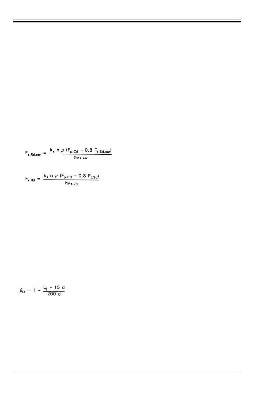
ENV 1993-1-1:1992
120
© BSI 04-2000
(3) Provided that the contact surfaces have been treated in conformity with Reference Standard 8 the
following surface treatments may be classified without further testing:
6.5.8.4 Combined tension and shear
(1) If a slip-resistant connection is subjected to an applied tensile force F
t
in addition to the shear force F
v
tending to produce slip, the slip resistance per bolt shall be taken as follows:
• Category B: Slip-resistant at serviceability:
• Category C: Slip-resistant at ultimate:
(2) If, in a moment connection, the applied tensile force is counterbalanced by a contact force on the
compression side, no reduction of the slip resistance is required.
6.5.9 Prying forces
(1) Where fasteners are required to carry an applied tensile force, they shall be proportioned to also resist
the additional force due to prying action, where this can occur, see Figure 6.5.8.
(2) The prying forces depend on the relative stiffness and geometrical proportions of the parts of the
connection, see Figure 6.5.9.
(3) If the effect of the prying force is taken advantage of in the design of the parts, then the prying force should
be determined by a suitable analysis analogous to that incorporated in the application runs given in
normative Annex J for beam-to-column connections.
6.5.10 Long joints
(1) Where the distance L
j
between the centres of the end fasteners in a joint, measured in the direction of
the transfer of force (see Figure 6.5.10), is more than 15 d, where d is the nominal diameter of the bolts or
rivets, the design shear resistance F
v.Rd
of all the fasteners calculated as specified in 6.5.5 or 6.5.6 as
appropriate shall be reduced by multiplying it by a reduction factor 
Lf
, given by:
(2) This provision does not apply where there is a uniform distribution of force transfer over the length of
the joint, e.g. the transfer of shear force from the web of a section to the flange.
In class A: — surfaces blasted with shot or grit, with any loose rust removed, no pitting;
— surfaces blasted with shot or grit, and spray-metallized with aluminium;
— surfaces blasted with shot or grit, and spray-metallized with a zinc-based coating
certified to provide a slip factor of not less than 0,5;
In class B: — surfaces blasted with shot or grit, and painted with an alkali-zinc silicate paint to
produce a coating thickness of 50–80 Èm.
In class C: — surfaces cleaned by wire brushing or flame cleaning, with any loose rust removed;
In class D: — surfaces not treated.
(6.9)
(6.10)
(6.11)
but 
Lf
k1,0 and 
Lf
U0,75
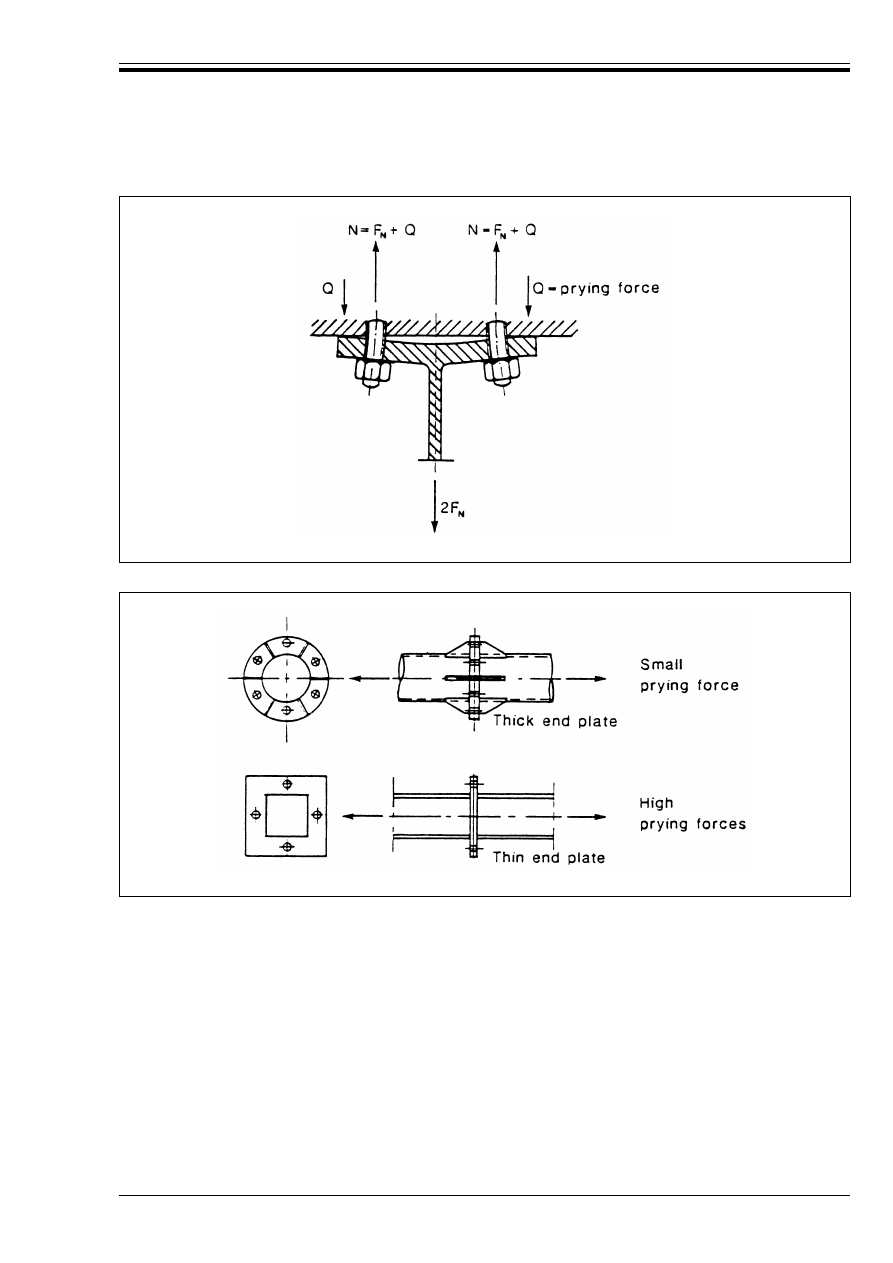
ENV 1993-1-1:1992
© BSI 04-2000
121
Figure 6.5.8 — Prying forces
Figure 6.5.9 — Effect of details on prying forces
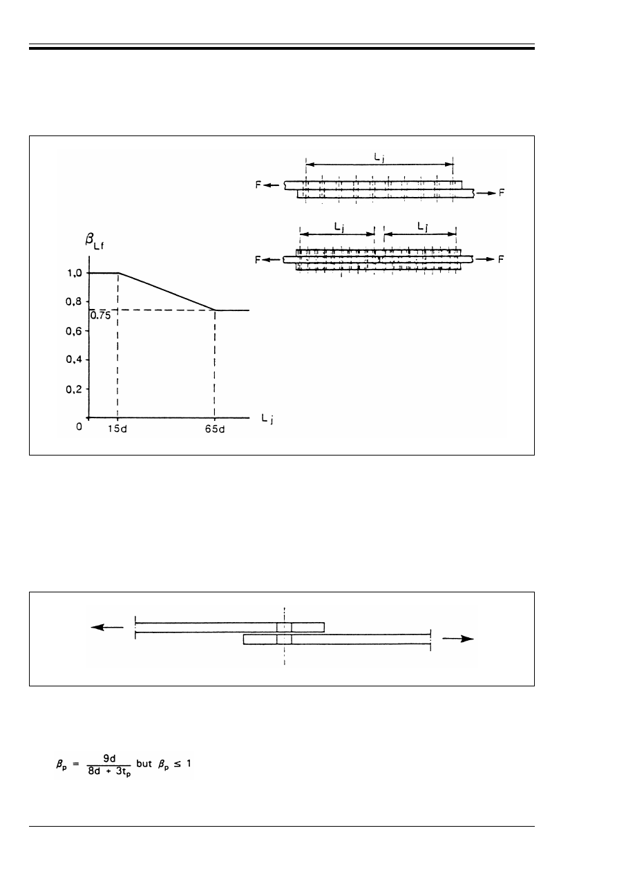
ENV 1993-1-1:1992
122
© BSI 04-2000
6.5.11 Single lap joints with one bolt
(1) In single lap joints of flats with only one bolt, see Figure 6.5.11, the bolt shall be provided with washers
under both the head and the nut to avoid pull-out failure.
(2) The bearing resistance F
b.Rd
determined in accordance with 6.5.5 shall be limited to:
(3) In the case of high strength bolts, grades 8.8 or 10.9, hardened washers should be used for single lap
joints of flats with only one bolt, even where the bolts are not preloaded.
6.5.12 Fasteners through packings
(1) Where bolts or rivets transmitting load in shear and bearing pass through packings of total thickness
t
p
greater than one-third of the nominal diameter d, the design shear resistance F
v.Rd
calculated as specified
in 6.5.5 or 6.5.6 as appropriate, shall be reduced by multiplying it by a reduction factor 
p
given by:
(2) For double shear connections with packings on both sides of the splice, t
p
should be taken as the thickness
of the thicker packing.
Figure 6.5.10 — Long joints
F
b.Rd
k 1,5 f
u
dt/¾
Mb
(6.12)
NOTE Single rivets should not be used in single lap joints.
Figure 6.5.11 — Single lap joint with one bolt
(6.13)
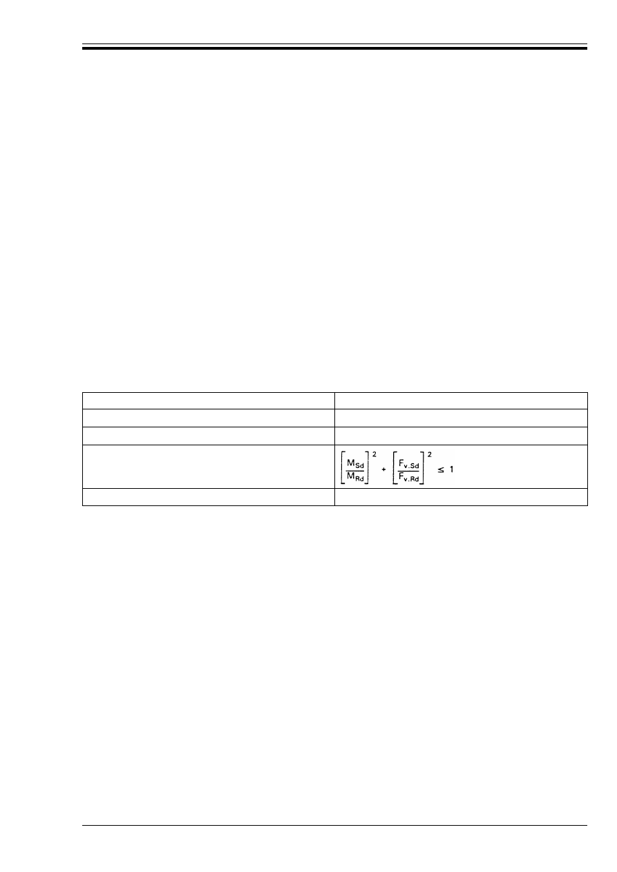
ENV 1993-1-1:1992
© BSI 04-2000
123
(3) Any additional fasteners required due to the application of the reduction factor 
p
may optionally be
placed in an extension of the packing.
6.5.13 Pin connections
6.5.13.1 Scope
(1) This clause applies to pin connections where free rotation is required. Pin connections in which no
rotation is required may be designed as single bolted connections, see 6.5.5 and 6.5.11.
6.5.13.2 Pin holes and pin plates
(1) The geometry of plates in pin connections shall be in accordance with the dimensional requirements
given in Table 6.5.6.
(2) At the ultimate limit state the design force N
Sd
in the plate shall not exceed the design bearing
resistance given in Table 6.5.7.
(3) Pin plates provided to increase the net area of a member or to increase the bearing resistance of a pin
shall be of sufficient size to transfer the design force from the pin into the member and shall be arranged
to avoid eccentricity.
6.5.13.3 Design of pins
(1) The bending moments in a pin should be calculated as indicated in Figure 6.5.12.
(2) At the ultimate limit state the design forces and moments in a pin shall not exceed the relevant design
resistances given in Table 6.5.7.
Table 6.5.7 — Design resistances for pin connections
Criterion
Resistance
Shear of the pin
F
v.Rd
= 0,6 A f
up
/¾
Mp
Bending of the pin
M
Rd
= 0,8 W
e
=
f
yp
/¾
Mp
Combined shear and bending of the pin
Bearing of the plate and the pin
F
b.Rd
= 1,5 t d f
y
/¾
Mp
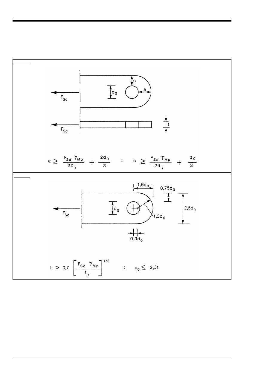
ENV 1993-1-1:1992
124
© BSI 04-2000
Table 6.5.6 — Geometrical conditions for plates in pin connections
Type A: Given thickness t
Type B: Given geometry
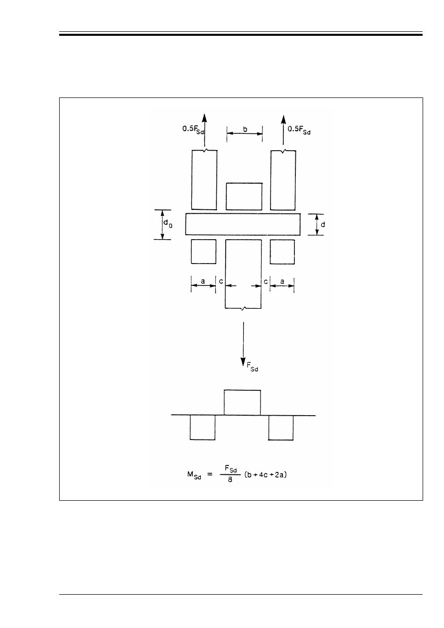
ENV 1993-1-1:1992
© BSI 04-2000
125
Figure 6.5.12 — Bending moment in a pin

ENV 1993-1-1:1992
126
© BSI 04-2000
6.6 Welded connections
6.6.1 General
(1) Connections made by welding shall comform with the relevant requirements concerning materials and
execution specified in Chapter 3 and Chapter 7.
(2) The provisions of section 6.6 apply to:
• Weldable structural steels meeting the requirements of section 3.2 and Chapter 7.
• Welding by an arc welding process, defined in accordance with EN..... “Welding processes”
20)
as
follows:
111 — metal-arc welding with covered electrodes
114 — flux-cored arc welding (without gas shield)
12 — submerged arc welding
131 — MIG (metal inert gas) welding
135 — MAG (metal active gas) welding
136 — flux-cored wire metal-arc welding (with active gas shield)
141 — TIG (tungsten inert gas) welding
• Material thicknesses of 4 mm and over. For welds in thinner material refer to ENV 1993-1-3
Eurocode 3-1.3
20)
.
• Joints in which the weld metal is compatible with the parent metal in terms of mechanical properties.
(3) Welds subject to fatigue shall also satisfy the requirements given in Chapter 9.
6.6.2 Geometry and dimensions
6.6.2.1 Type of weld
(1) For the purpose of this Eurocode, welds shall generally be classified as:
• fillet welds,
• slot welds,
• butt welds,
• plug welds, or
• flare groove welds.
(2) Butt welds may be either:
• full penetration butt welds, or
• partial penetration butt welds.
(3) Both slot welds and plug welds may be in either:
• circular holes, or
• elongated holes.
(4) Weld classification is illustrated in Table 6.6.1.
20)
In preparation
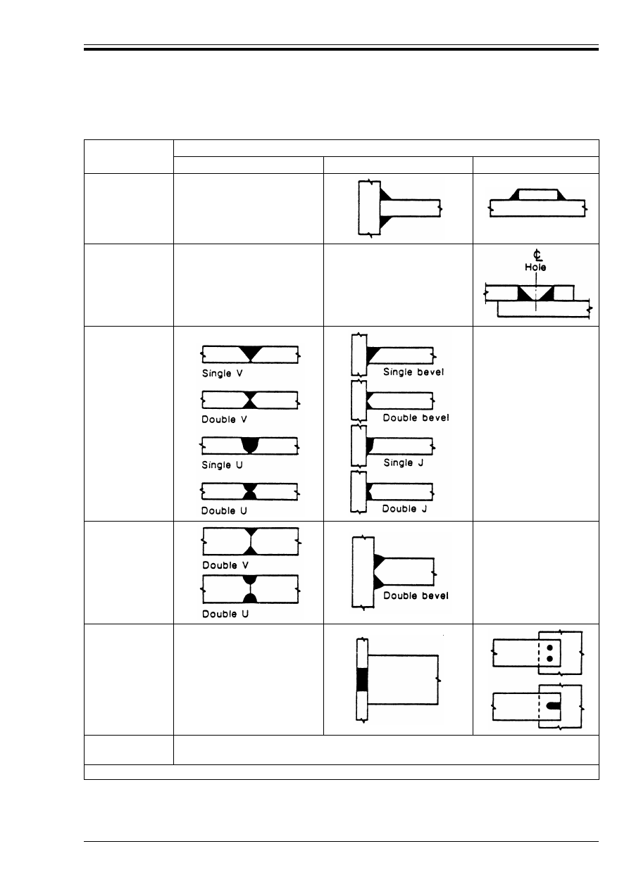
ENV 1993-1-1:1992
© BSI 04-2000
127
Table 6.6.1 — Common types of welded joints
Type of weld
Type of joint
Butt joint
Tee-butt joint
Lap joint
Fillet weld
Slot weld
Full penetration
butt weld
a
Partial
penetration butt
weld
a
Plug weld
Flare groove
welds
See Figure 6.6.3 and Figure 6.6.4
a
Butt welds can sometimes be formed without cutting any weld preparation in either component

ENV 1993-1-1:1992
128
© BSI 04-2000
6.6.2.2 Fillet welds
(1) Fillet welds may be used for connecting parts where the fusion faces form an angle of between 60°
and 120°.
(2) Smaller angles than 60° are also permitted. However, in such cases the weld shall be considered to be
a partial penetration butt weld.
(3) For angles over 120°, fillet welds shall not be relied upon to transmit forces.
(4) Fillet welds should not terminate at corners of parts or members, but should be returned continuously,
full sized, around the corner for a length equal to twice the leg size of the weld, wherever such a return can
be made in the same plane.
(5) End returns should be indicated on the drawings.
(6) Fillet welds may be continuous or intermittent.
(7) Intermittent fillet welds shall not be used in corrosive conditions.
(8) In an intermittent fillet weld, the clear unconnected gaps between the ends of each length of
weld (see Figure 6.6.1) shall not be more than the smallest of:
a) 200 mm;
b) 12 times the thickness of the thinner part when the part connected is in compression;
c) 16 times the thickness of the thinner part when the part connected is in tension;
d) one-quarter of the distance between stiffeners, when used to connect stiffeners to a plate or other part
subjected to compression or shear.
(9) In an intermittent fillet weld, the clear unconnected gap shall be measured between the ends of welds
on opposing sides or on the same side, whichever is shorter.
(10) In any run of intermittent fillet welds there shall always be a length of weld at each end of the part
connected.
(11) In a fabricated member in which plates are connected by means of intermittent fillet welds, a
continuous fillet weld shall be provided on each side of the plate for a length at each end equal to at least
three-quarters of the width of the narrower plate concerned (see Figure 6.6.1).
(12) A single fillet weld shall not be used to transmit a bending moment about the longitudinal axis of the
weld if it produces tension at the root of the weld, nor to transmit a significant tensile force perpendicular
to the longitudinal axis of the weld in situations which would effectively produce such a bending moment.
(13) A fillet weld may be used as part of a weld group around the perimeter of a structural hollow section,
see Figure 6.6.2(a), but should not be used in the situation indicated in Figure 6.6.2(c).
(14) When a single fillet weld is used to transmit a force perpendicular to its longitudinal axis, the
eccentricity of the weld (relative to the line of action of the force to be resisted) shall be taken into account.
(15) There is normally no eccentricity of this nature in welded connections of structural hollow sections.
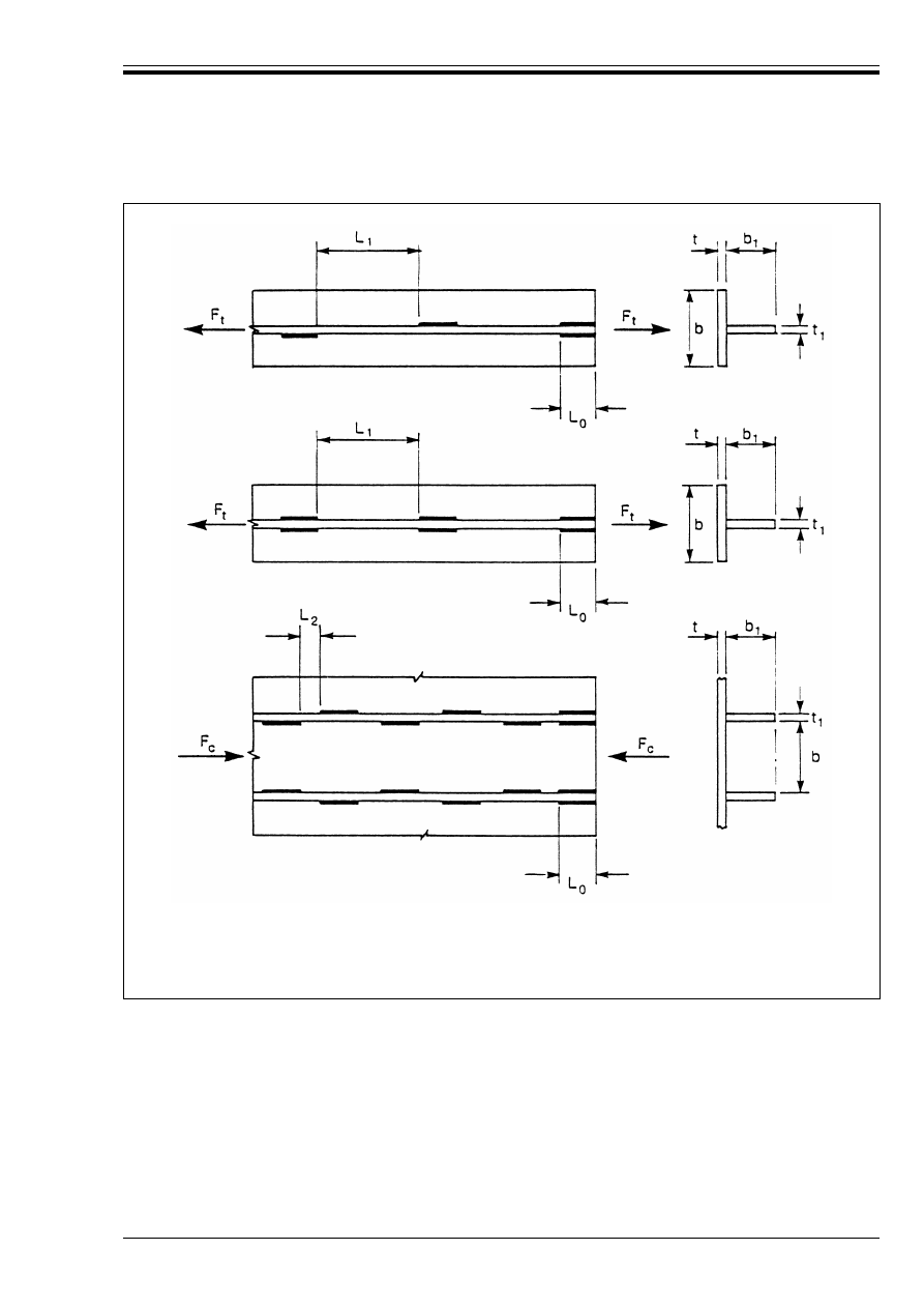
ENV 1993-1-1:1992
© BSI 04-2000
129
L
0
U 0,75b or 0,75b
1
— whichever is smaller
L
1
k 16t or 16t
1
or 200 mm — whichever is smallest
L
2
k 12t or 12t
1
or 0,25b or 200 mm — whichever is smallest
Figure 6.6.1 — Intermittent fillet welds
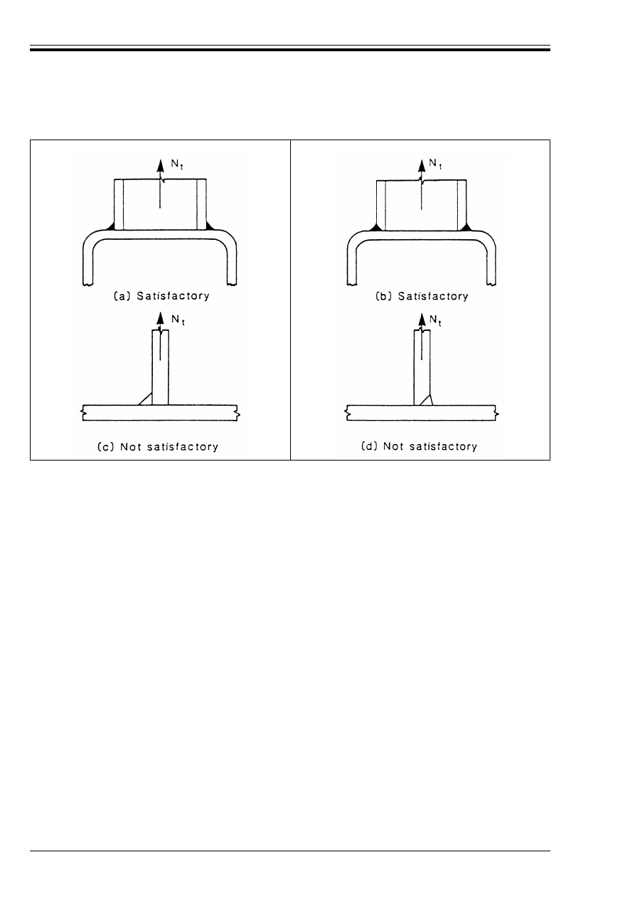
ENV 1993-1-1:1992
130
© BSI 04-2000
6.6.2.3 Slot welds
(1) Slot welds, comprising fillet welds in circular or elongated holes, may be used only to transmit shear or
to prevent the buckling or separation of lapped parts.
(2) The diameter of a circular hole, or width of an elongated hole, for a slot weld shall not be less than four
times the thickness of the part containing it.
(3) The ends of elongated holes shall be semi-circular, except for those ends which extend to the edge of the
part concerned.
6.6.2.4 Butt welds
(1) A full penetration butt weld is defined as a butt weld that has complete penetration and fusion of weld
and parent metal throughout the thickness of the joint.
(2) A partial penetration butt weld is defined as a butt weld that has joint penetration which is less than
the full thickness of the parent material.
(3) A single-sided partial penetration butt weld shall not be used to transmit a bending moment about the
longitudinal axis of the weld if it produces tension at the root of the weld, nor to transmit a significant
tensile force perpendicular to the longitudinal axis of the weld in situations which would effectively produce
such a bending moment.
(4) A single sided partial penetration butt weld may be used as part of a weld group around the perimeter of
a structural hollow section, see Figure 6.6.2(b), but should not be used in the situation indicated in
Figure 6.6.2(d).
(5) When a single-sided partial penetration weld is used to transmit a force perpendicular to its
longitudinal axis, the eccentricity of the weld (relative to the line of action of the force to be resisted) shall
be taken into account.
(6) There is normally no eccentricity of this nature in welded connections of structural hollow sections.
(7) Intermittent butt welds shall not be used.
Figure 6.6.2 — Single fillet welds and single-sided partial penetration butt welds
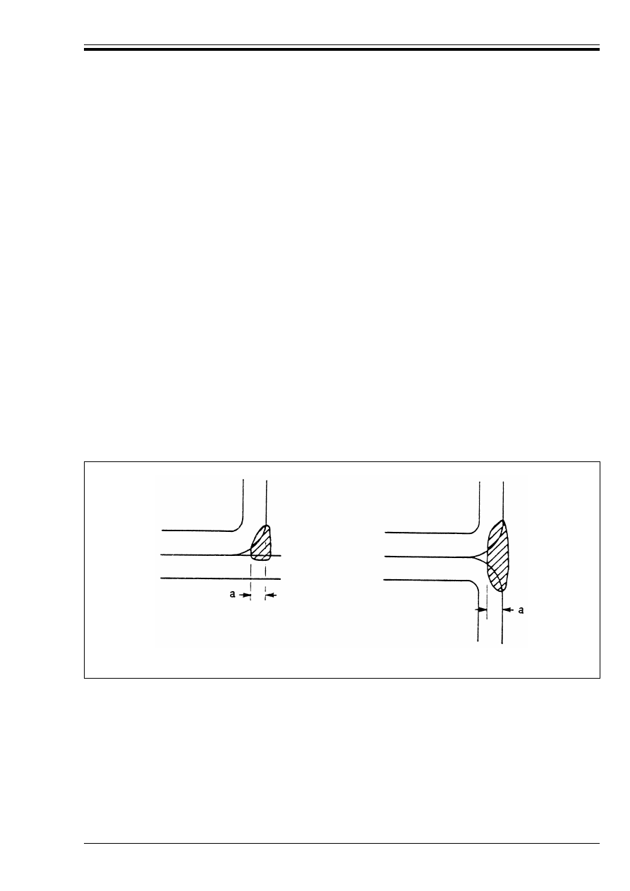
ENV 1993-1-1:1992
© BSI 04-2000
131
6.6.2.5 Plug welds
(1) Plug welds, comprising welds which fill circular or elongated holes, shall not be used to resist externally
applied tension, but they may be used:
• to transmit shear, or
• to prevent the buckling or separation of lapped parts, or
• to inter-connect the components of built-up members.
(2) The diameter of a circular hole, or width of an elongated hole, for a slot weld shall be at least 8 mm more
than the thickness of the part containing it.
(3) The ends of elongated holes shall either be semi-circular or else shall have corners which are rounded
to a radius of not less than the thickness of the part containing the slot, except for those ends which extend
to the edge of the part concerned.
(4) The thickness of a plug weld in material up to 16 mm thick shall be equal to the thickness of the
material. The thickness of a plug weld in material over 16 mm thick shall be at least half the thickness of
the material and not less than 16 mm.
(5) The centre to centre spacing of plug welds shall not exceed the value necessary to prevent local buckling.
6.6.2.6 Flare groove welds
(1) In rectangular structural hollow sections the effective throat thickness of flare-V and
flare-bevel-groove welds (see Figure 6.6.3) shall be determined by means of trial welds for each set of
procedural conditions.
(2) The trial welds shall be sectioned and measured to establish welding techniques that will ensure that
the design throat thickness is achieved in production.
(3) For solid bars the same procedure shall be used to determine the effective throat thickness of
flare-groove welds, when fitted flush to the surface of the solid section of the bars (see Figure 6.6.4).
Figure 6.6.3 — Effective throat of flare groove welds in rectangular
structural hollow sections
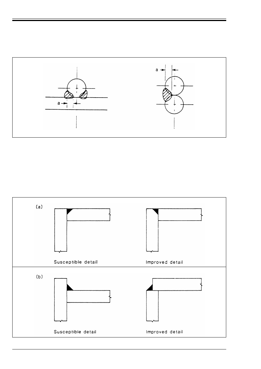
ENV 1993-1-1:1992
132
© BSI 04-2000
6.6.3 Lamellar tearing
(1) Joint details causing through-thickness stresses originating from welding carried out under conditions
of restraint shall be avoided whenever possible.
(2) Where such details are unavoidable, appropriate measures shall be taken to minimise the possibility of
lamellar tearing.
(3) If tensile stresses perpendicular to the surface of the part (due to external loads or due to residual welding
stresses) occur in a flat part more than 15 mm thick, then the combination of the welding procedure, the
through-thickness properties of the material and the joint detail, see Figure 6.6.5, should be such as to avoid
lamellar tearing.
Figure 6.6.4 — Effective throat of flare groove welds in solid sections
Figure 6.6.5 — Avoiding lamellar tearing

ENV 1993-1-1:1992
© BSI 04-2000
133
6.6.4 Distribution of forces
(1) The distribution of forces in a welded connection may be calculated on the assumption of either elastic
or plastic behaviour in conformity with 6.1.3 and 6.1.4.
(2) Normally it is acceptable to assume a simplified load distribution within the welds.
(3) Residual stresses and stresses not participating in the transfer of load need not be included when
checking the resistance of a weld. This applies specifically to the normal stress parallel to the axis of a weld.
(4) Welded connections shall be designed to have adequate deformation capacity.
(5) In joints where plastic hinges may form, the welds shall be designed to provide at least the same design
resistance as the weakest of the connected parts.
(6) In other joints where deformation capacity for joint rotation is required due to the possibility of
excessive straining, the welds require sufficient strength not to rupture before general yielding in the
adjacent parent material.
(7) In general this will be satisfied if the design resistance of the weld is not less than 80 % of the design
resistance of the weakest of the connected parts.
6.6.5 Design resistance of a fillet weld
6.6.5.1 Effective length
(1) The effective length of a fillet weld shall be taken as the overall length of the full-size fillet, including
end returns. Provided that the weld is full size throughout this length, no reduction in effective length need
be made for either the start or the termination of the weld.
(2) Welds with effective lengths shorter than 40 mm or 6 times the throat thickness, whichever is larger,
should be ignored for transmission of forces.
(3) Where the stress distribution along a weld is significantly influenced by the stiffness of the members or
parts joined, the non-uniformity of the stress distribution may be neglected, provided that the design
resistance is correspondingly reduced.
(4) The effective breadths of welded joints designed to transfer transverse loads to an unstiffened flange of
an I, H or box section should be reduced as specified in 6.6.8.
(5) The design resistances of welds in long joints should be reduced as specified in 6.6.9.
6.6.5.2 Throat thickness
(1) The throat thickness, a, of a fillet weld shall be taken as the height of the largest triangle which can be
inscribed within the fusion faces and the weld surface, measured perpendicular to the outer side of this
triangle, see Figure 6.6.6.
(2) The throat thickness of a fillet weld should not be less than 3 mm.
(3) In determining the resistance of a deep penetration fillet weld, account may be taken of its additional
throat thickness, see Figure 6.6.7, provided that it is shown by preliminary trials that the required
penetration can consistently be achieved.
(4) In the case of a fillet weld made by an automatic submerged arc process, the throat thickness may be
increased by 20 % or 2 mm, whichever is smaller, without resorting to preliminary trials.
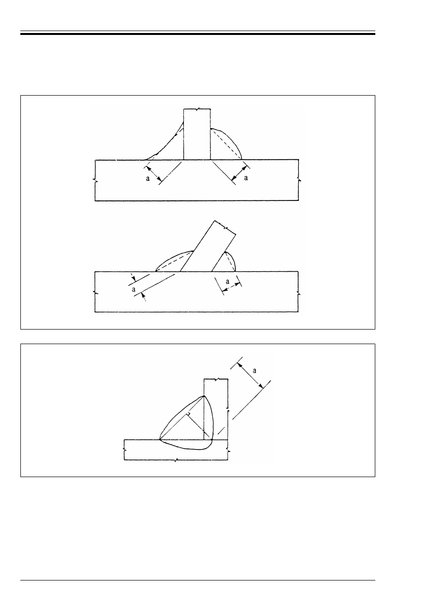
ENV 1993-1-1:1992
134
© BSI 04-2000
6.6.5.3 Resistance per unit length
(1) The design resistance per unit length of a fillet weld shall be determined using either the method given
below, or else the alternative method given in normative Annex M.
(2) The resistance of a fillet weld may be assumed to be adequate if, at every point in its length, the
resultant of all the forces per unit length transmitted by the weld does not exceed its design resistance
F
w.Rd
.
(3) Independent of the orientation of the weld, the design resistance per unit length F
w.Rd
shall be
determined from:
Figure 6.6.6 — Throat thickness of a fillet weld
Figure 6.6.7 — Throat thickness of a deep penetration fillet weld
F
w.Rd
= f
vw.d
a
(6.14)

ENV 1993-1-1:1992
© BSI 04-2000
135
(4) The design shear strength f
vw.d
of the weld shall be determined from:
(5) The value of the correlation factor 
w
should be taken as follows:
(6) For intermediate values of f
u
, the value of 
w
may be determined by linear interpolation.
6.6.6 Design resistance of butt welds
6.6.6.1 Full penetration butt welds
(1) The design resistance of a full penetration butt weld shall be taken as equal to the design resistance of
the weaker of the parts joined, provided that the weld is made with a suitable electrode (or other welding
consumable) which will produce all-weld tensile specimens having both a minimum yield strength and a
minimum tensile strength not less than those specified for the parent metal.
6.6.6.2 Partial penetration butt welds
(1) The resistance of a partial penetration butt weld shall be determined as for a deep penetration fillet
weld, see 6.6.5.
(2) The throat thickness of a partial penetration butt weld shall be taken as the depth of penetration that
can consistently be achieved.
(3) The throat thickness that can consistently be achieved may be determined by preliminary trials.
(4) Where the weld preparation is of the U, V, J or bevel type, see Figure 6.6.8, the throat thickness should
be taken as the nominal depth of preparation minus 2 mm, unless a larger value is shown to be justified by
preliminary trials.
6.6.6.3 Tee-butt joints
(1) The resistance of a tee-butt joint, consisting of a pair of partial penetration butt welds reinforced by
superimposed fillet welds, may be determined as for a full penetration butt weld (see 6.6.6.1) if the total
nominal throat thickness, exclusive of the unwelded gap, is not less than the thickness t of the part forming
the stem of the tee joint, provided that the unwelded gap is not more than (t/5) or 3 mm, whichever is less,
see Figure 6.6.9(a).
(2) The resistance of a tee-butt joint which does not meet the requirements given in (1) shall be determined
as for a deep penetration fillet weld, see 6.6.5. The throat thickness shall be determined in conformity with
the provisions for both fillet welds (see 6.6.5.2) and partial penetration butt welds (see 6.6.6.2).
(3) The throat thickness should be taken as the nominal throat thickness minus 2 mm [see Figure 6.6.9(b)],
unless a larger value is shown to be justified by preliminary trials.
where f
vw.d
is the design shear strength of the weld.
(6.15)
where f
u
is the nominal ultimate tensile strength of the weaker part joined.
and 
w
is the appropriate correlation factor.
Steel grade
Ultimate tensile
strength f
u
Correlation factor
w
EN 10025:
Fe 360
360 N/mm
2
0,8
Fe 430
430 N/mm
2
0,85
Fe 510
510 N/mm
2
0,9
prEN 10113:
Fe E 275
390 N/mm
2
0,8
Fe E 355
490 N/mm
2
0,9
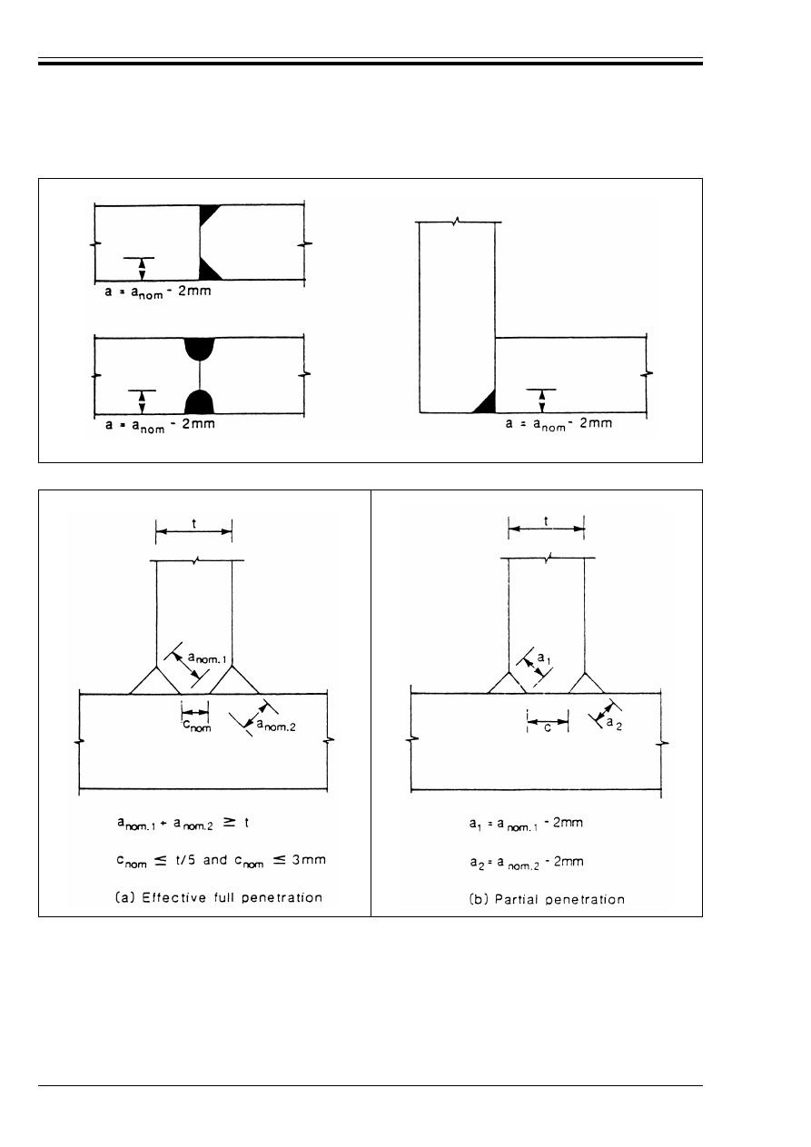
ENV 1993-1-1:1992
136
© BSI 04-2000
6.6.7 Design resistance of plug welds
(1) The design resistance F
w.Rd
of a plug weld (see 6.6.2.5) shall be taken as f
vw.d
A
w
, where f
vw.d
is the design
shear strength of a weld given in 6.6.5.3(4).
(2) The effective area A
w
of a plug weld shall be taken as the area of the hole.
(3) Slot welds (see 6.6.2.3) shall be considered as fillet welds. The design resistance of a slot weld shall be
determined from 6.6.5.
Figure 6.6.8 — Partial penetration butt welds
Figure 6.6.9 — Tee-butt welds
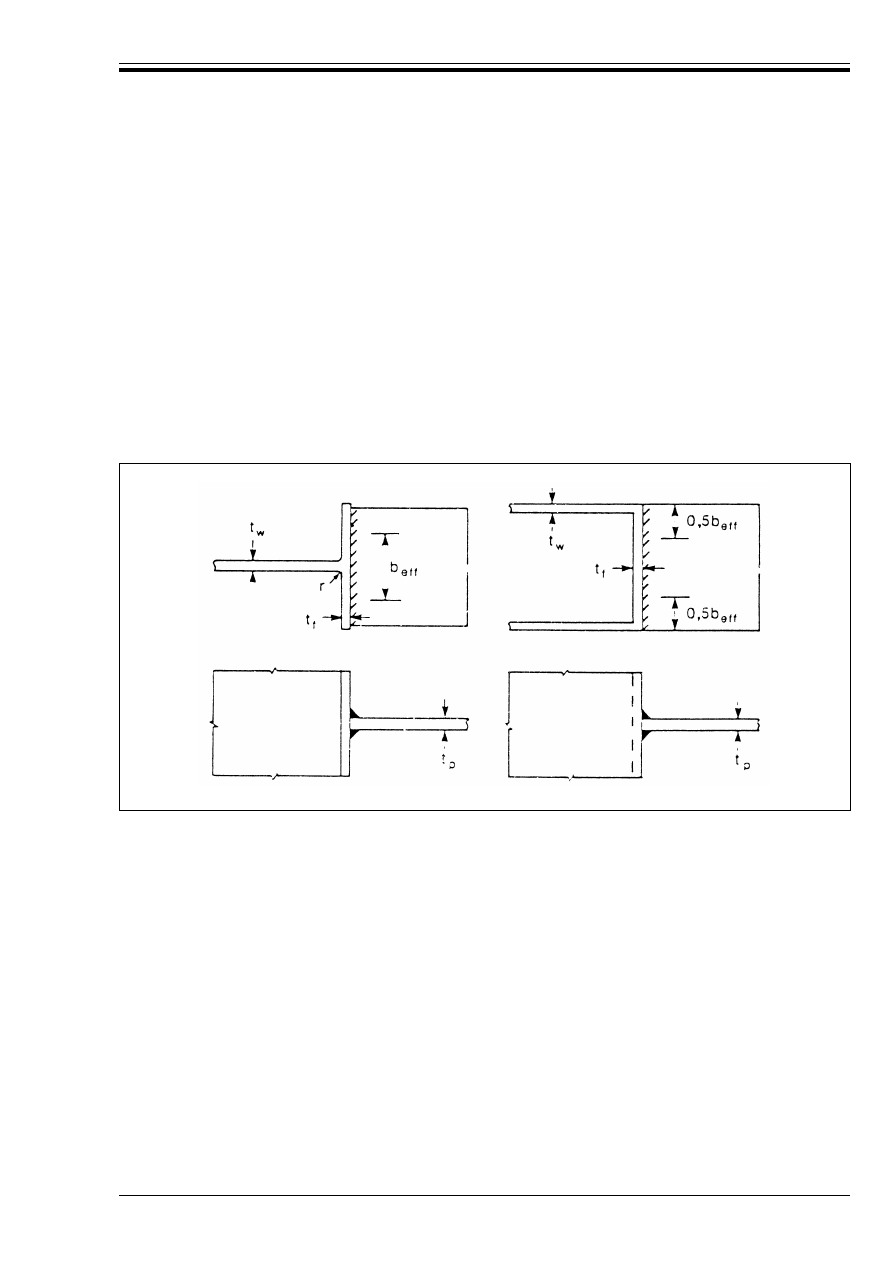
ENV 1993-1-1:1992
© BSI 04-2000
137
6.6.8 Joints to unstiffened flanges
(1) In a tee-joint of a plate to an unstiffened flange of an I, H or a box section, a reduced effective breadth
shall be taken into account both for the parent material and for the welds, see Figure 6.6.10.
(2) For an I or H sect/on the effective breadth b
eff
should be obtained from:
(3) If b
eff
is less than 0,7 times the full breadth, the joint should be stiffened.
(4) For a box section the effective breadth b
eff
should be obtained from:
(5) The welds connecting the plate to the flange shall have a design resistance per unit length not less than
the design resistance per unit width of the plate.
6.6.9 Long joints
(1) In lap joints the design resistance of a fillet weld shall be reduced by multiplying it by a reduction
factor 
Lw
to allow for the effects of non-uniform distribution of stress along its length.
(2) This provision does not apply when the stress distribution along the weld corresponds to the stress
distribution in the adjacent base metal, as, for example, in the case of a weld connecting the flange and the
web of a plate girder.
(3) Generally in lap joints longer than 150a the reduction factor 
Lw
should be taken as 
Lw.1
given by:
(4) For fillet welds longer than 1,7 metres connecting transverse stiffeners in plated members, the reduction
factor 
Lw
may be taken as 
Lw.2
given by:
b
eff
= t
w
+ 2r + 7t
f
but
b
eff
k t
w
+ 2r + 7(t
f
2
/t
p
)(f
y
/f
yp
)
(6.16)
where f
Y
is the design strength of the member
and f
Yp
is the design strength of the plate.
b
eff
= 2t
w
+ 5t
f
but
b
eff
k2t
w
+ 5(t
f
2
/t
p
) (f
y
/f
yp
)
(6.17)
Figure 6.6.10 — Effective breadth of an unstiffened tee-joint
Lw.1
= 1,2 – 0,2L
j
/(150a)
(6.18)
but 
Lw.1
k 1,0
where L
j
is the overall length of the lap in the direction of the force transfer.
Lw.2
= 1,1 – L
w
/17
(6.19)
but 
Lw.2
k 1,0 and 
Lw.2
U 0,6
where L
j
is the length of the weld (in metres).
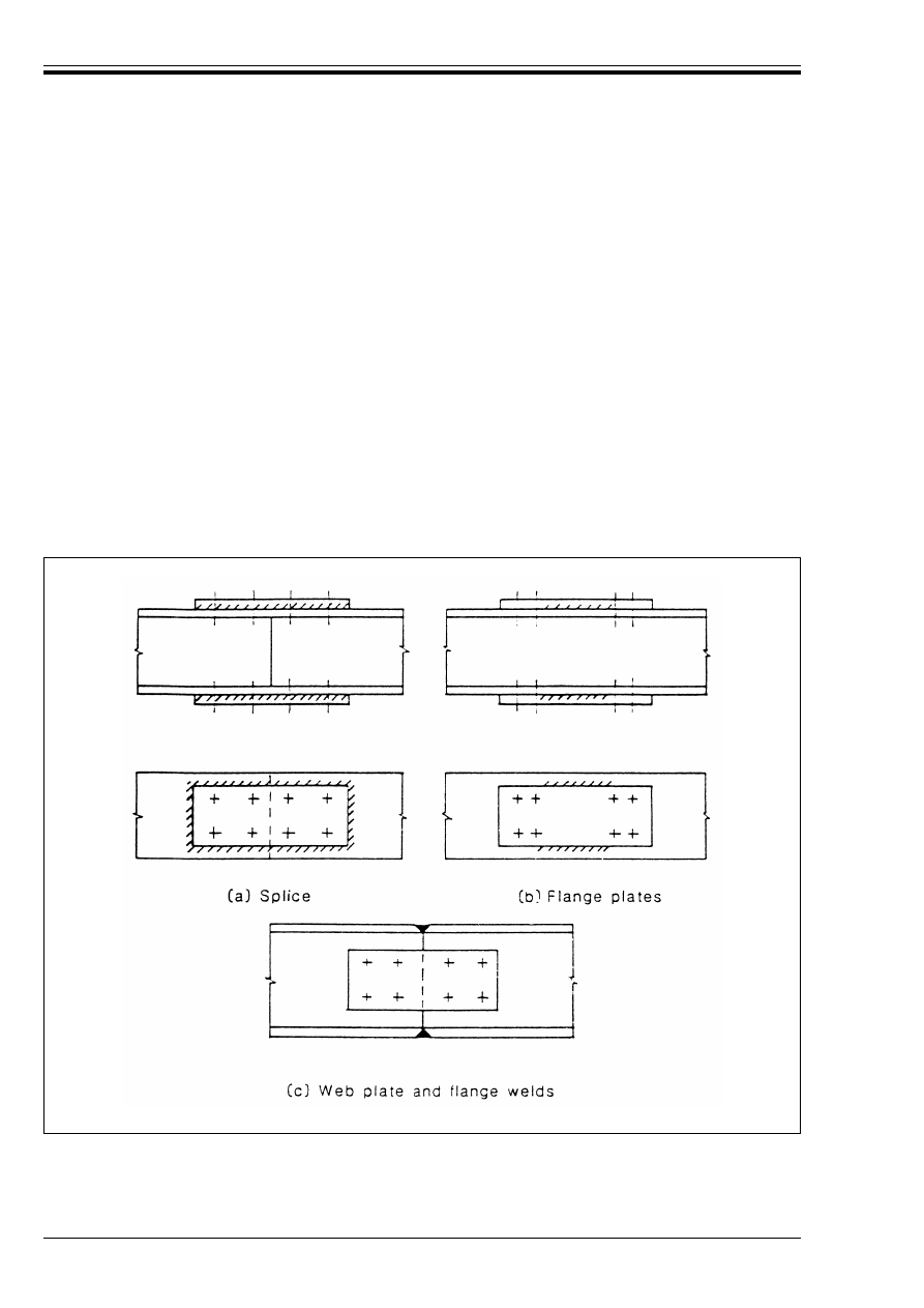
ENV 1993-1-1:1992
138
© BSI 04-2000
6.6.10 Angles connected by one leg
(1) In angles connected by one leg, the eccentricity of welded lap joint end connections may be allowed for
by adopting an effective cross-sectional area and then treating the member as concentrically loaded.
(2) For an equal-leg angle, or an unequal-leg angle connected by its larger leg, the effective area may be taken
as equal to the gross area.
(3) For an unequal-leg angle connected by its smaller leg, the effective area should be taken as equal to the
gross cross-sectional area of an equivalent equal-leg angle of leg size equal to that of the smaller leg, when
determining the design resistance of the cross-section, see 5.4.3 and 5.4.4. However when determining the
design buckling resistance of a compression member, see 5.5.1, the actual gross cross-sectional area should
be used.
6.7 Hybrid connections
(1) When different forms of fasteners are used to carry a shear load or when welding and fasteners are used
in combination, see Figure 6.7.1, then one form of connector shall normally be designed to carry the total
load.
(2) As an exception to this provision, preloaded high-strength bolts in connections designed as
slip-resistant at the ultimate limit state (Category C in 6.5.3.1) may be assumed to share load with welds,
provided that the final tightening of the bolts is carried out after the welding is complete.
Figure 6.7.1 — Hybrid connections

ENV 1993-1-1:1992
© BSI 04-2000
139
6.8 Splices
6.8.1 General
(1) This section applies to the design of joints within the length of a member or other structural part.
(2) Splices shall be designed to hold the connected members in place.
(3) Wherever practicable the members shall be arranged so that the centroidal axis of any splice material
coincides with the centroidal axis of the member. If eccentricity is present then the resulting forces shall
be taken into account.
6.8.2 Splices in compression members
(1) Where the members are not prepared for full contact in bearing, splice material shall be provided to
transmit the internal forces and moments in the member at the spliced section, including the moments due
to applied eccentricity, initial imperfections and second order deformations.
(2) Where the members are prepared for full contact in bearing, the splice shall be designed to provide
continuity of stiffness about both axes and to resist any tension where moments are present for any reason,
including those given in (1).
(3) The alignment of the abutting ends shall be maintained by cover plates or other means. The splice
material and its fastenings shall be proportioned to carry a force at the abutting ends, acting in any
direction perpendicular to the axis of the member, of not less than 2,5 % of the compressive force in the
member.
6.8.3 Splices in tension members
(1) A splice in a member or part subject to tension shall be designed to transmit all the moments and forces
to which the member of part is subjected at that point.
6.9 Beam-to-column connections
6.9.1 Basis
(1) The design moment resistance M
Rd
of a beam-to-column connection shall not be less than the applied
design moment M
Sd
.
(2) The moment-rotation characteristics of a beam-to-column connection shall be consistent with the
assumptions made in the global analysis of the structure and with the assumptions made in the design of
the members, see 5.2.2.1.
6.9.2 Moment-rotation characteristic
(1) The determination of the design moment-rotation characteristics of beam-to-column connections shall
be based on theory supported by experimental evidence.
(2) As an approximation to the real behaviour, a beam-to-column connection may be represented by a
rotational spring connecting the centre lines of the column and the connected beam at the point of
intersection, as indicated in Figure 6.9.1.
(3) Generally the actual moment-rotation characteristic of a beam-to-column connection is non-linear.
(4) An approximate design moment-rotation characteristic may be derived from a more precise
characteristic by adopting any appropriate curve, including a linearised approximation (e.g. bi-linear or
tri-linear), provided that the approximate curve lies wholly below the more precise characteristic,
see Figure 6.9.2.
(5) A design moment-rotation characteristic (see Figure 6.9.3) shall define three main properties, as
follows:
• moment resistance (see 6.9.3)
• rotational stiffness (see 6.9.4)
• rotation capacity (see 6.9.5)
(6)When using elastic global analysis it is not necessary to consider the rotation capacity of rigid or
se mi-rigid connections, see 6.4.2.
(7) In certain cases the moment-rotation behaviour of a beam-to-column connection includes some initial
rotation due to bolt slip or lack of fit, as indicated in Figure 6.9.4. Where this occurs, an initial hinge
rotation Ì
o
shall also be included in the design moment-rotation characteristic, see Figure 6.9.4(b).
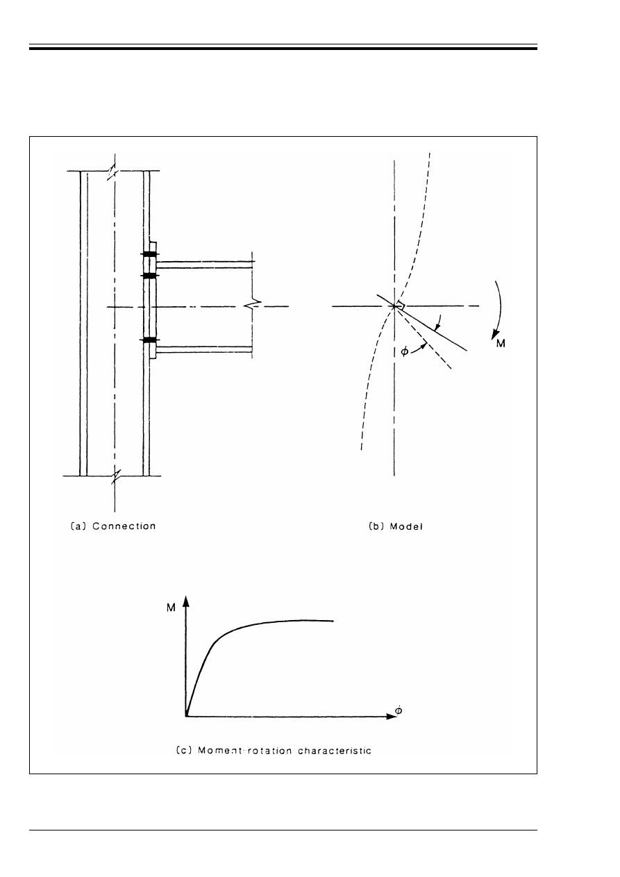
ENV 1993-1-1:1992
140
© BSI 04-2000
Figure 6.9.1 — Modelling a connection as a rotational spring

ENV 1993-1-1:1992
© BSI 04-2000
141
6.9.3 Moment resistance
(1) The design moment resistance M
Rd
is equal to the peak value of the design moment-rotation
characteristic.
6.9.4 Rotational stiffness
(1) Full benefit may be taken of a non-linear design moment-rotation characteristic by using incremental
calculation procedures.
(2) Except as indicated in (1), the rotational stiffness S
j
shall be taken as the secant stiffness as indicated
in Figure 6.9.5.
(3) Different values of the secant stiffness may be used, depending on the design moment M
Sd
for the load
case and limit state under consideration, see Figure 6.9.6.
6.9.5 Rotation capacity
(1) The design rotation capacity Ì
Cd
of a beam-to-column connection shall be taken as the rotation achieved
at the maximum design moment resistance of the connection, see Figure 6.9.7.
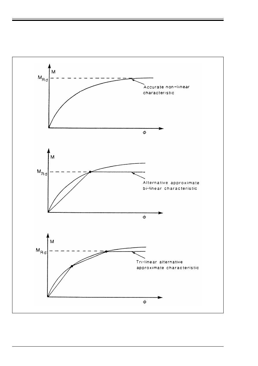
ENV 1993-1-1:1992
142
© BSI 04-2000
Figure 6.9.2 — Derivation of approximate moment-rotation characteristics
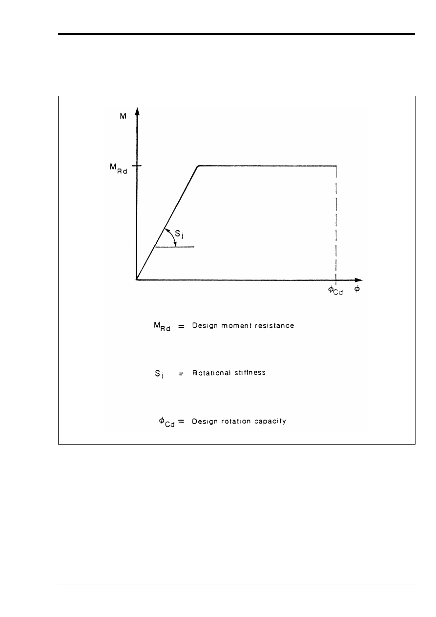
ENV 1993-1-1:1992
© BSI 04-2000
143
Figure 6.9.3 — Properties of a design moment-rotation characteristic
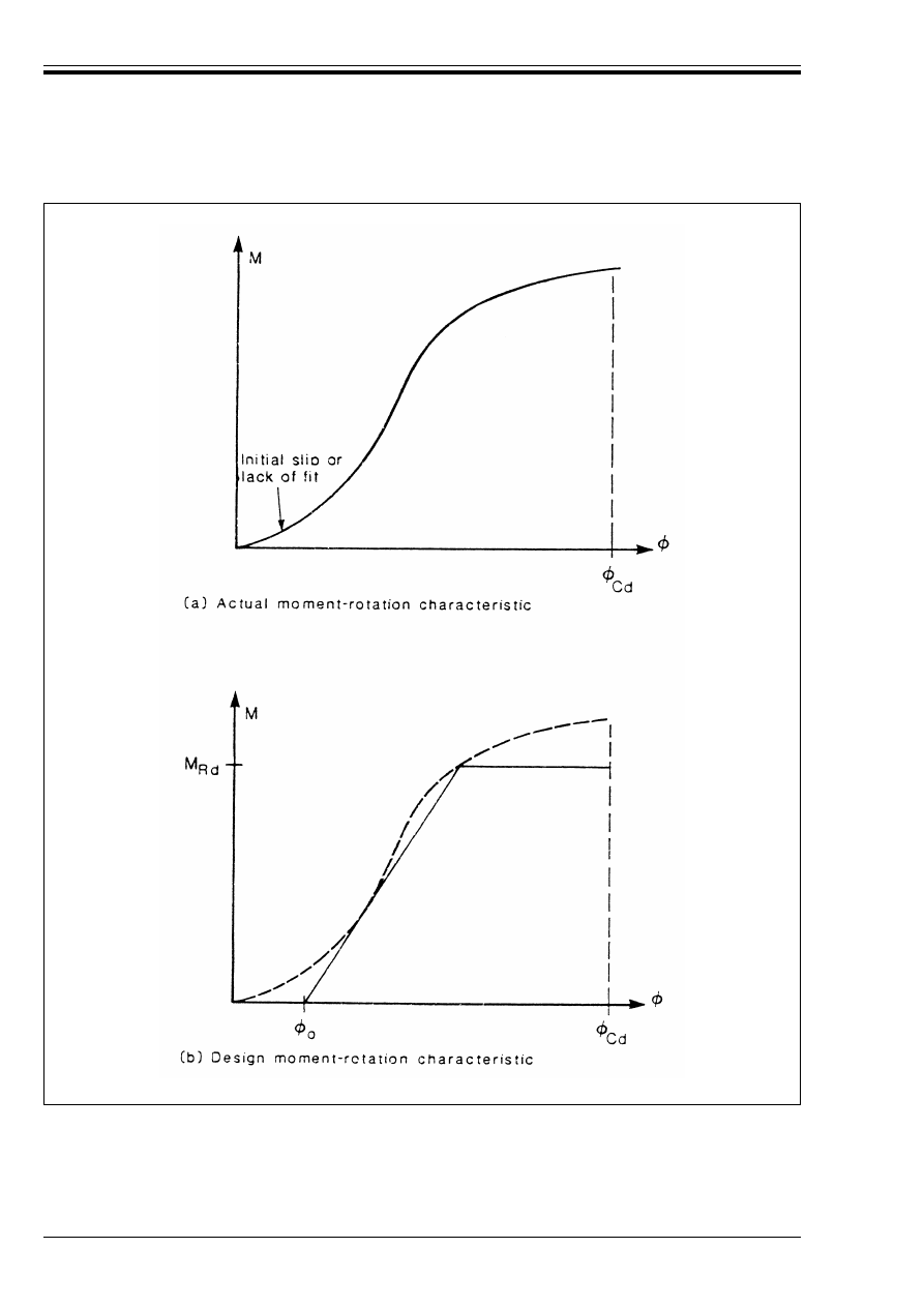
ENV 1993-1-1:1992
144
© BSI 04-2000
Figure 6.9.4 — Moment-rotation characteristic with an initial hinge rotation
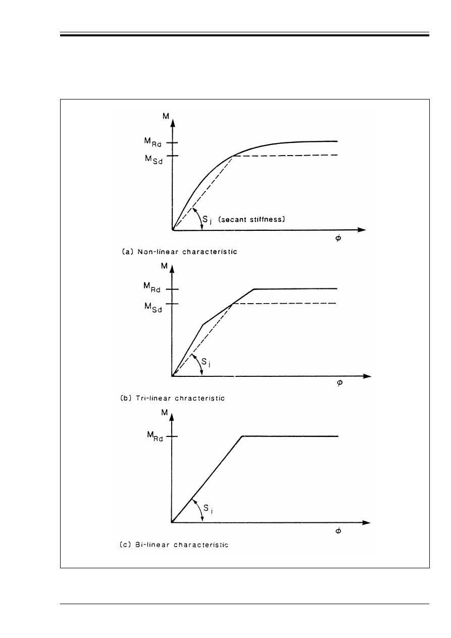
ENV 1993-1-1:1992
© BSI 04-2000
145
Figure 6.9.5 — Rotational stiffness S
j
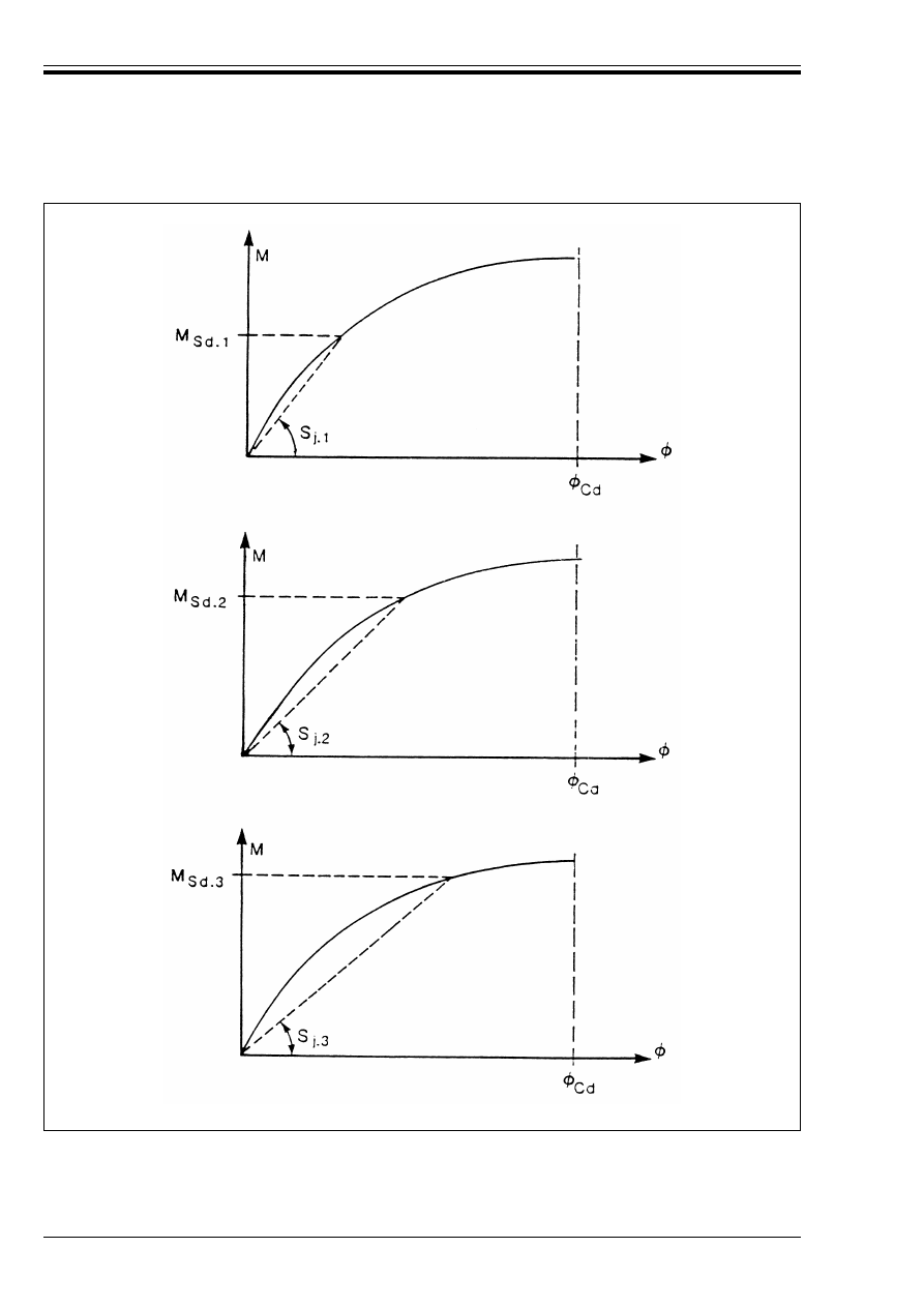
ENV 1993-1-1:1992
146
© BSI 04-2000
Figure 6.9.6 — Variation of rotational stiffness with applied moment
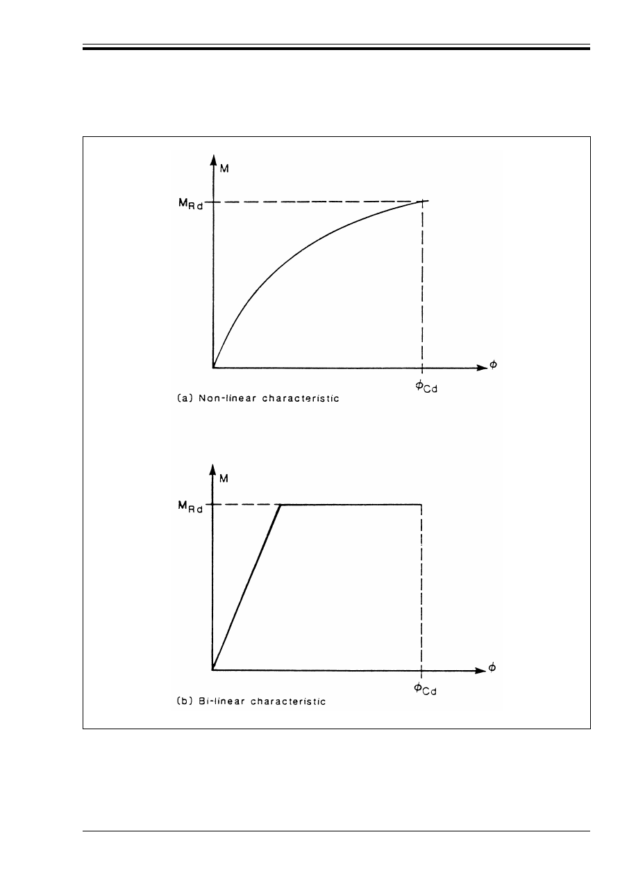
ENV 1993-1-1:1992
© BSI 04-2000
147
6.9.6 Classification of beam-to-column connections
6.9.6.1 Basis
(1) Beam-to-column connections may be classified:
• by rotational stiffness, see 6.9.6.2.
• by moment resistance, see 6.9.6.3.
Figure 6.9.7 — Rotation capacity Ì
Cd

ENV 1993-1-1:1992
148
© BSI 04-2000
6.9.6.2 Rotational stiffness
(1) The rotational stiffness of a beam-to-column connection may be classified as:
• nominally pinned, see 6.4.2.1.
• rigid, see 6.4.2.2.
• semi-rigid, see 6.4.2.3.
(2) A beam-to-column connection may be classified as rigid or nominally pinned on the basis of particular
or general experimental evidence, or significant experience of previous satisfactory performance in similar
cases or by calculations based on test evidence.
(3) A beam-to-column connection may be classified as nominally pinned if its rotational stiffness S
j
(based on a moment rotation characteristic representative of its actual anticipated behaviour) satisfies the
condition:
(4) A beam-to-column connection in a braced frame, or in an unbraced frame which satisfies the condition
specified in (5), may be considered to be rigid compared to the connected beam, if the rising portion of its
moment-rotation characteristic lies above the solid line on the appropriate diagram in Figure 6.9.8.
(5) The line given in Figure 6.9.8(a) for an unbraced frame may be used only for frames in which every storey
satisfies:
(6) If the rising portion of its moment-rotation characteristic lies below the appropriate line in Figure 6.9.8,
a beam-to-column connection should be classified as semi-rigid, unless it also satisfies the requirements for
a nominally pinned connection.
(7) Connections which are classified as rigid or nominally pinned, may optionally be treated as semi-rigid.
6.9.6.3 Moment resistance
(1) With respect to the design moment resistance, beam-to-column connections may be classified as:
• nominally pinned, see 6.4.3.1.
• full-strength, see 6.4.3.2.
• partial-strength, see 6.4.3.3.
(2) A beam-to-column connection may be classified as nominally pinned if its design moment resistance M
Rd
is not greater than 0,25 times the design plastic moment resistance of the connected beam M
p
=
.Rd
, provided
that it also has sufficient rotation capacity.
(3) A beam-to-column connection may be classified as full-strength if its design moment resistance M
Rd
is at
least equal to the design plastic moment resistance of the connected beam M
p
=
.Rd
, provided that it also has
sufficient rotation capacity.
(4) If the design moment resistance M
Rd
of a beam-to-column connection is at least 1,2 times the design
plastic moment resistance of the member M
p
=
.Rd
, the rotation capacity of the connection need not be checked.
(5) A beam-to-column connection should be classified as partial-strength if its design moment resistance M
Rd
is less than M
p
=
.Rd
.
S
j
k0,5 El
b
/L
b
(6.20)
where S
j
is the secant rotational stiffness of the connection, see 5.9.4.
l
b
is the second moment of area of the connected beam.
L
b
is the length of the connected beam.
K
b
/K
c
U 0,1
(6.21)
in which K
b
is the mean value of l
b
/L
b
for all the beams at the top of that storey
and
K
c
is the mean value of l
c
/L
c
for all the columns in that storey
where
l
b
is the second moment of area of a beam
l
c
is the second moment of area of a column
L
b
is the span of a beam (centre-to-centre of columns)
L
c
is the storey height for a column
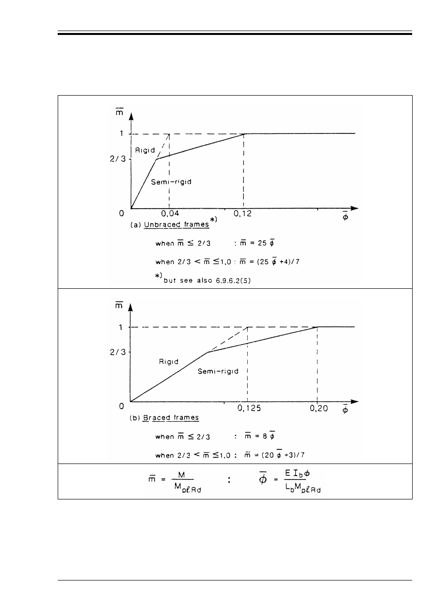
ENV 1993-1-1:1992
© BSI 04-2000
149
6.9.6.4 Classification of moment-rotation characteristics
(1) The classification of typical moment-rotation characteristics for beam-to-column connections with respect
to both rotational stiffness and moment resistance, is illustrated in Figure 6.9.9.
(2) The moment-rotation characteristics indicated in Figure 6.9.9 are shown as non-linear for clarity. The
figure is equally valid for hi-linear or tri-linear characteristics.
Figure 6.9.8 — Recommended classification boundaries for rigid beam-to-column
connections

ENV 1993-1-1:1992
150
© BSI 04-2000
Figure 6.9.9 — Examples of classification of moment-rotation characteristics for
beam-to-column connections

ENV 1993-1-1:1992
© BSI 04-2000
151
6.9.7 Calculated properties
6.9.7.1 Moment resistance
(1) The moment resistance of a beam-to-column connection depends on the resistance of the three critical
zones indicated in Figure 6.9.10, as follows:
• Tension zone
• Compression zone
• Shear zone.
(2) The design moment resistance shall be determined taking account of the following criteria:
a) Tension zone:
• Yielding of the column web.
• Yielding of the beam web.
• Yielding of the column flange.
• Yielding of the connection material (e.g. end plate).
• Weld failure.
• Bolt failure.
b) Compression zone:
• Crushing of the column web.
• Buckling of the column web.
c) Shear zone:
• Shear failure of the column web panel.
(3) The design resistance of the compression zone may be influenced by local second order effects caused by
normal stresses in the column due to the frame behaviour.
(4) Except as indicated in (3), the design resistances of the critical zones of the connection may be assumed
to be unaffected by stresses due to the frame behaviour.
(5) The design moment resistance of a beam-to-column connection shall be taken as the smaller of the
resistances of the tension zone and the compression zone, (reduced if necessary so that the design shear
resistance of the column web panel is not exceeded), multiplied by the distance between their centres of
resistance.
(6) Where the design resistance of the shear zone is greater than or equal to the smaller of the design
resistances of the tension zone and the compression zone, no further check on the shear resistance of the
column web panel is required.
6.9.7.2 Rotational stiffness
(1) The calculated rotational stiffness of a beam-to-column connection shall be based on the flexibilities of
the components in the critical zones.
6.9.7.3 Rotation capacity
(1) The validity of calculation procedures used to determine rotation capacity shall be verified from test
evidence.
(2) The calculated rotation capacity of a beam-to-column connection shall be determined from the plastic
deformation capacity of the same critical zone which governs in the calculation of the design moment
resistance of the connection.
6.9.8 Application rules
(1) The principles for the design of beam-to-column connections given in section 6.9 can be satisfied by
following the detailed application rules given in normative Annex J.
(2) The design of other types of connection not covered in normative Annex J should be based on similar
application rules conforming to the principles given in section 6.9.
(3) Alternative application rules can also be used provided that:
• they accord with the same principles, and
• it can be demonstrated that they lead to at least the same safety level
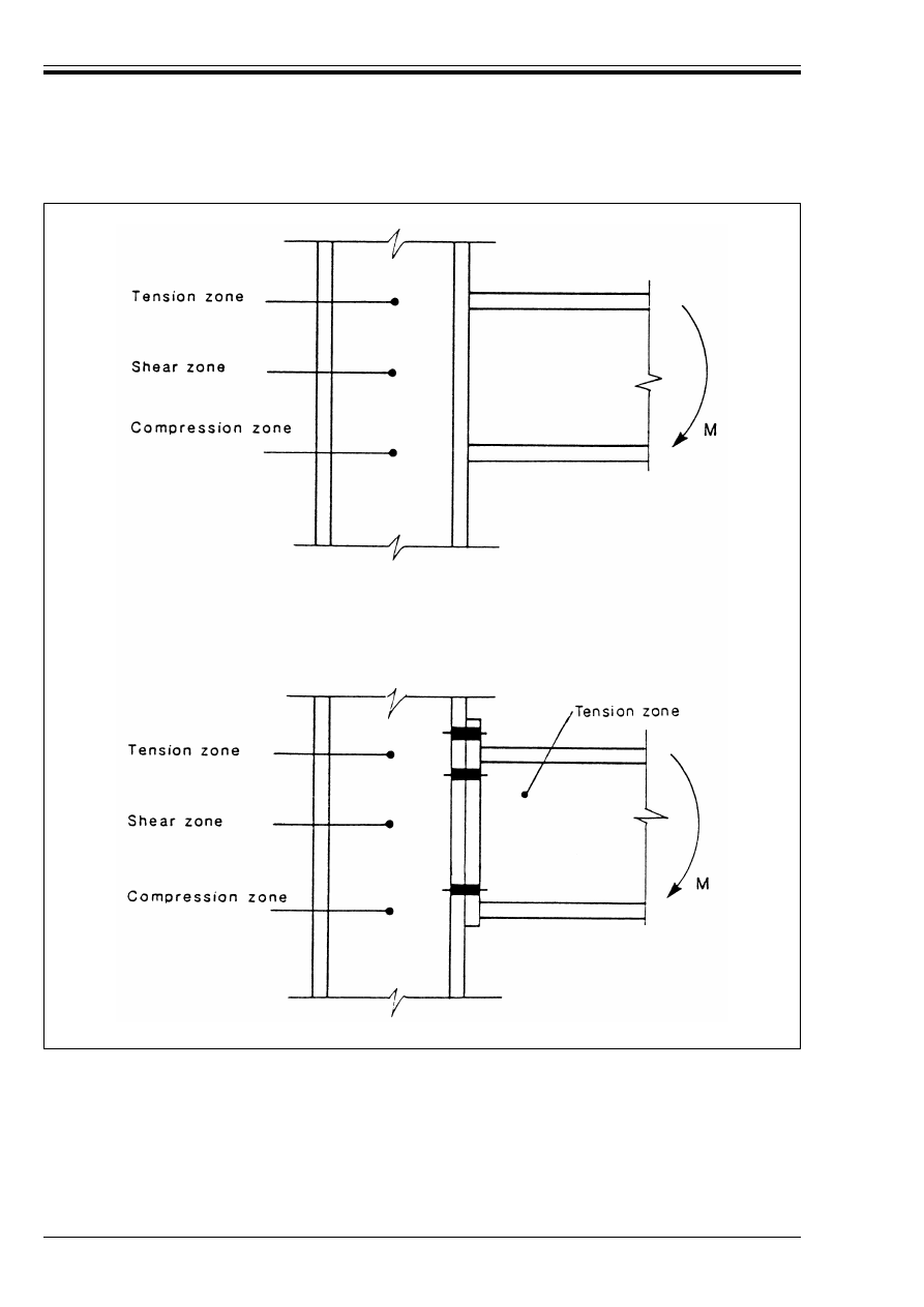
ENV 1993-1-1:1992
152
© BSI 04-2000
6.10 Hollow section lattice girder joints
6.10.1 Design resistance
(1) The design resistances of joints between hollow sections shall be based on the following criteria as
applicable:
a) chord face failure.
b) chord web (or wall) failure by yielding or instability.
Figure 6.9.10 — Critical zones in beam-to-column connections

ENV 1993-1-1:1992
© BSI 04-2000
153
c) chord shear failure.
d) chord punching shear failure.
e) brace failure with reduced effective width.
f) local buckling failure.
(2) The welds shall be designed to have sufficient resistance and ductility to allow redistribution of
non-uniform stress distributions and to allow redistribution of secondary bending moments.
6.10.2 Application rules
(1) The principles for the design of hollow section lattice girder joints given in section 6.10 can be satisfied
by following the detailed application rules given in normative Annex K.
(2) Alternative application rules can also be used provided that:
• they accord with the same principles, and
• it can be demonstrated that they lead to at least the same safety level.
6.11 Column bases
6.11.1 Base plates
(1) Columns shall be provided with base plates capable of distributing the compressive forces in the
compressed parts of the column over a bearing area, such that the bearing pressure on the foundation does
not exceed the design strength of the joint.
(2) The design strength of the joint between the base plate and the foundation shall be determined taking
account of the material properties and dimensions of both the grout and the concrete foundation.
6.11.2 Holding down bolts
(1) Holding down bolts shall be provided if necessary to resist the effects of the design loads. They shall be
designed to resist tension due to uplift forces and tension due to bending moments as appropriate.
(2) When calculating the tension forces due to bending moments, the lever arm shall not be taken as more
than the distance between the centroid of the bearing area on the compression side and the centroid of the
bolt group on the tension side, taking the tolerances on the positions of the holding down bolts into account.
(3) Holding down bolts shall either be anchored into the foundation by a hook or by a washer plate or by
some other appropriate load distributing member embedded in the concrete.
(4) If no special elements for resisting the shear force are provided, such as block or bar shear connectors,
it shall be demonstrated that sufficient resistance to transfer the shear force between the column and the
foundation is provided by one of the following:
• the frictional resistance of the joint between the base plate and the foundation
• the shear resistance of the holding down bolts
• the shear resistance of the surrounding part of the foundation
6.11.3 Application rules
(1) The principles for the design of column bases given in section 6.11 can be satisfied by following the
detailed application rules given in normative Annex L.
(2) Alternative application rules can also be used provided that:
• they accord with the same principles, and
• it can be demonstrated that they lead to at least the same safety level.
7 Fabrication and erection
7.1 General
7.1.1 Scope
(1) This chapter specifies the minimum standards of workmanship required for fabrication and erection to
ensure that the design assumptions of this Eurocode are satisfied and hence that the intended level of
structural safety can be attained.

ENV 1993-1-1:1992
154
© BSI 04-2000
(2) The minimum requirements apply to structures which are predominantly statically loaded. Higher
standards of workmanship and more rigorous levels of inspection and testing may be necessary for
structures in which fatigue predominates, depending on the design details and the required fatigue
strength (see Chapter 9) or for other reasons.
(3) Any supplementary requirements specific to particular structures shall be stated in the Project
Specification.
7.1.2 Requirements
(1) Provided that all structural steel materials, fasteners and welding consumables conform with the
requirements specified in Chapter 3, the workmanship shall be in conformity with the following Reference
Standards:
• Reference Standard No. 6: Fabrication of structural steelwork
• Reference Standard No. 7: Erection of structural steelwork
• Reference Standard No. 8: Installation of preloaded bolts
• Reference Standard No. 9: Welding of structural steelwork
NOTE For details of Reference Standards 6 to 9 see normative Annex B.
(2) If any alternative or additional materials are used, the requirements specified in (1) shall be
supplemented as necessary to ensure a similar level of safety.
7.2 Project specification
(1) The designer shall provide, or adopt, a Project Specification containing details of all the requirements
for materials, fabrication and erection necessary to ensure compliance with the design assumptions
relevant to the particular structure.
(2) The Project Specification shall contain adequate details of any special requirements for:
• fabrication
• erection
• inspection
• acceptance.
(3) The Project Specification shall cover all relevant requirements arising from the requirements of
sections 7.3 to 7.7 of this Chapter.
(4) The Project Specification may include drawings in addition to text.
(5) The Project Specification may supplement the requirements of the Reference Standards but it shall not
relax their technological requirements and it shall not supersede the minimum requirements specified in
this Chapter.
(6) Once approved the Project Specification shall not be altered without the agreement of the designer and
of the authority responsible for inspection.
(7) As far as possible the requirements in the Project Specification should be specified using the Reference
Standards.
7.3 Fabrication restrictions
(1) It is necessary to avoid or eliminate hardened material in the following situations:
• when design is based on plastic analysis, within a distance along the member equal to the depth of
the member, either side of each plastic hinge location.
• when fatigue predominates, where detail categories 140 or 160 (see Chapter 9) are used in design.
• where design for seismic actions or accidental actions relies on plastic deformation.
(2) Where any of the situations listed in (1) occurs, the locations required to be free from hardened material
shall be identified in the Project Specification.
(3) At locations required to be free of hardened material, the restrictions specified in Reference Standard 6
shall be applied to the following:
a) flame cut or sheared edges
b) punched holes

ENV 1993-1-1:1992
© BSI 04-2000
155
c) hard marking
d) temporary welded attachments
e) surface repair by welding
NOTE Condition e) affects the supply conditions for the material, see Reference Standard 1.
(4) All locations where restrictions on hardening are required should be clearly indicated on the drawings.
7.4 Preparation of material
(1) Any necessary straightening or shaping shall be done using methods that do not reduce the properties
of the material below those specified.
(2) Steelwork that has been galvanised shall be re-straightened or re-shaped if necessary to satisfy the
specified tolerance limits.
(3) All surfaces and edges shall be free from defects likely to impair the effectiveness of the surface
protection system specified in the Project Specification.
(4) The standards of flatness necessary at contact bearing surfaces to transmit the design forces shall be
specified.
(5) Any special treatment required at cut-outs shall be specified in the Project Specification.
7.5 Bolted connections
7.5.1 Holes
(1) Holes for bolts may be drilled or punched unless specified otherwise.
(2) Where drilled holes are required they may be sub-punched and reamed.
(3) Where countersunk holes are required, the angle of countersinking shall correspond to that of standard
countersunk bolts as specified in Reference Standard 3, unless special non-standard countersunk bolts are
specified.
(4) Care should be taken that the depth of countersinking is sufficient to accommodate the head of the bolt.
Where this would involve countersinking into more than one ply the action to be taken should be stated in
the Project Specification.
(5) Slotted holes shall either be punched in one operation or else formed by punching or drilling two round
holes and completed by high quality flame cutting and dressing to ensure that the bolt can freely travel the
full length of the slot.
7.5.2 Clearances in holes for fasteners
(1) Except for fitted bolts or where low-clearance or oversize holes are specified, the nominal clearance in
standard holes shall be:
• 1 mm for M12 and M14 bolts
• 2 mm for M16 to M24 bolts
• 3 mm for M27 and larger bolts.
(2) Holes with smaller clearances than standard holes may be specified.
(3) Holes with 2 mm nominal clearance may also be specified for M12 and M14 bolts, provided that the
design meets the requirements specified in 6.5.5(8).
(4) Unless special clearances are specified, the clearance for fitted bolts shall be as specified in Reference
Standard 6.
(5) Oversize and slotted holes may be used for slip-resistant connections only where specified.
(6) The nominal clearance in oversize holes for slip-resistant connections shall be:
• 3 mm for M12 bolts
• 4 mm for M14 to M22 bolts
• 6 mm for M24 bolts
• 8 mm for M27 and larger bolts.
(7) Oversize holes in the outer ply of a slip-resistant connection shall be covered by hardened washers.

ENV 1993-1-1:1992
156
© BSI 04-2000
(8) Holes for holding down bolts may be oversize holes with clearances as specified in the Project
Specification, provided that these holes are covered by cover plates of appropriate dimensions and
thickness. The holes in the cover plates shall not be larger than standard holes.
(9) The nominal sizes of short slotted holes for slip resistant connections shall be not greater than:
• (d + 1) mm by (d + 4) mm for M12 and M14 bolts
• (d + 2) mm by (d + 6) mm for M16 to M22 bolts
• (d + 2) mm by (d + 8) mm for M24 bolts
• (d + 3) mm by (d + 10) mm for M27 and larger bolts
where d is the nominal bolt diameter in mm.
(10) The nominal sizes of long slotted holes for slip resistant connections shall be not greater than:
• (d + 1 ) mm by 2,5d for M12 and M14 bolts
• (d + 2) mm by 2,5d for M16 to M24 bolts
• (d + 3) mm by 2,5d for M27 and larger bolts
(11) Long slots in an outer ply shall be covered by cover plates of appropriate dimensions and thickness.
The holes in the cover plates shall not be larger than standard holes.
(12) The sizes required for long slotted holes for movement joints shall be specified. Slots in an outer ply
shall be covered by cover plates of appropriate dimensions and thickness.
7.5.3 Bolts
(1) Where design is based on bolts with unthreaded shanks in the shear plane, appropriate measures shall
be specified to ensure that, after allowing for tolerances, neither the threads nor the thread
run-out will be in the shear plane.
(2) Bolts with threads up to the head may be used except where prohibited by the Project Specification.
(3) The length of a non-preloaded bolt shall be such that, after allowing for tolerances:
• the threaded shank will protrude beyond the nut after tightening, and
• at least one full thread (in addition to the thread run-out) will remain clear between the nut and the
unthreaded part of the shank.
(4) The length of a preloaded bolt shall be such that, after allowing for tolerances:
• the threaded shank will protrude beyond the nut after tightening, and
• at least four full threads (in addition to the thread run-out) will remain clear between the nut and the
unthreaded part of the shank.
7.5.4 Nuts
(1) For structures subject to vibration, measures shall be taken to avoid any loosening of the nuts.
(2) If non-preloaded bolts are used in structures subject to vibrations, the nuts should be secured by locking
devices or other mechanical means.
(3) The nuts of preloaded bolts may be assumed to be sufficiently secured by the normal tightening procedure.
7.5.5 Washers
(1) Washers are not required for non-preloaded bolts except as follows:
• A taper washer shall be used where the surface is inclined at more than 3° to a plane perpendicular to
the bolt axis.
• Washers shall be used where this is necessary due to a requirement, specified in the Project
Specification, to use a longer bolt in order to keep the bolt threads out of a shear plane or out of a fitted
hole.
(2) Hardened washers shall be used for preloaded bolts as follows:
• A hardened washer shall be used under the bolt head or the nut, whichever is to be rotated.
• A hardened washer shall also be used under the non-rotated component (bolt head or nut) where
specified in the Project Specification.
• A hardened taper washer shall be used if necessary to ensure that the rotated component bears on a
surface perpendicular to the bolt axis.
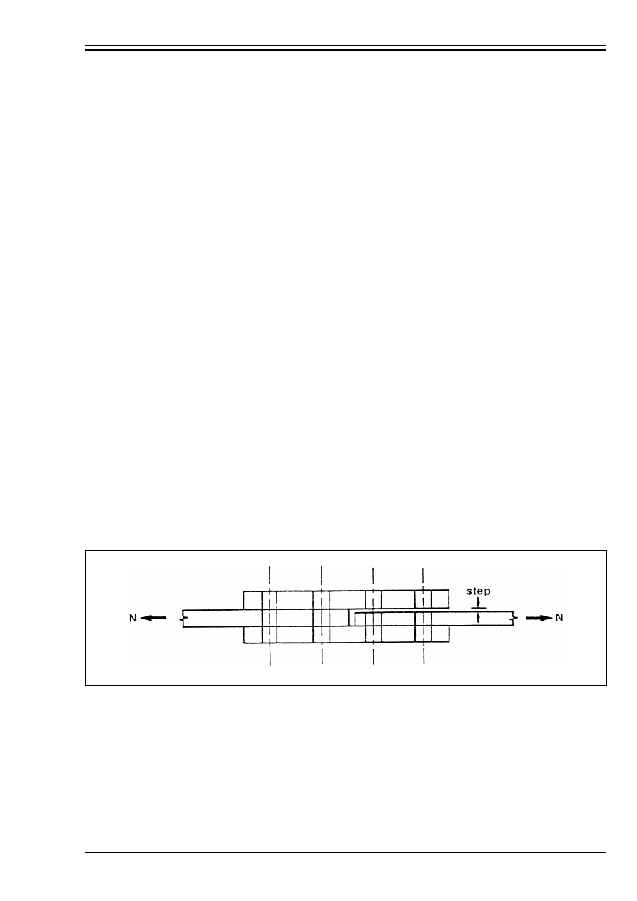
ENV 1993-1-1:1992
© BSI 04-2000
157
• A hardened taper washer shall be used under the non-rotated component where the surface is
inclined at more than 3° to a plane perpendicular to the bolt axis.
7.5.6 Tightening of bolts
(1) Non-preloaded bolts shall be tightened sufficiently to ensure that sufficient contact is achieved between
the parts assembled.
(2) It is not necessary to tighten non-preloaded bolts to a predetermined value. However as an indication, the
tightening required should be:
• that which can be achieved by one man using a normal podger spanner, or
• up to the point where an impact wrench first starts to impact.
(3) Preloaded bolts shall be tightened in conformity with Reference Standard 8. The Project Specification
shall specify which of the methods given in the Reference Standard may be used.
7.5.7 Slip resistant contact surfaces
(1) Where a particular surface condition is required at friction interfaces in bolted joints, the surface
condition required shall be specified in the Project Specification, see 6.5.8.3.
(2) If steel packing plates are used in a slip-resistant joint, it shall be ensured that their contact surfaces
are also prepared to the specified condition.
7.5.8 Fit of contact surfaces
(1) Unless smaller values are specified in the Project Specification, the maximum step between adjacent
surfaces in a joint (see Figure 7.1) shall not exceed:
• 2 mm when using non-preloaded bolts
• 1 mm when using preloaded bolts.
(2) When using preloaded bolts, the designer should consider allowing for the possible effects of lack of fit as
an alternative to imposing smaller tolerances.
(3) Steel packing plates shall be provided where necessary to ensure that the remaining step does not
exceed the specified limit.
(4) Unless a greater value is specified the minimum thickness of a steel packing plate should be:
• 2 mm in indoor conditions, if not exposed to corrosive influences
• 4 mm in outdoor conditions or if exposed to corrosive influences
7.6 Welded connections
(1) Assembly and welding shall be carried out in such a way that the final dimensions are within the
appropriate tolerances.
(2) The Project Specification shall include appropriate details of any welded connections which require:
• special welding procedures
• special levels of quality control
• special inspection procedures
• special test procedures.
Figure 7.1 — Maximum step between adjacent surfaces

ENV 1993-1-1:1992
158
© BSI 04-2000
(3) Welding may be carried out on site unless prohibited by the Project Specification.
(4) The drawings should indicate clearly whether butt welds are intended to be full penetration butt welds
or partial penetration butt welds. In the case of partial penetration butt welds, the required throat size
should be specified.
7.7 Tolerances
7.7.1 Types of tolerances
(1) “Normal” tolerances are the basic limits for dimensional deviations necessary:
• to satisfy the design assumptions for statically loaded structures.
• to define acceptable tolerances for building structures in the absence of any other requirements.
(2) “Special” tolerances are more stringent tolerances necessary to satisfy the design assumptions:
• for structures other than normal building structures.
• for structures in which fatigue predominates.
(3) “Particular” tolerances are more stringent tolerances necessary to satisfy functional requirements of
particular structures or structural components, related to:
• attachment of other structural or non-structural components
• shafts for lifts (elevators)
• tracks for overhead cranes
• other criteria such as clearances
• alignment of external face of a building
7.7.2 Application of tolerances
(1) All tolerance values specified in section 7.7 shall be treated as “normal” tolerances.
(2) “Normal” tolerances apply to conventional single-storey and multi-storey steel framed structures of
residential, administrative, commercial and industrial buildings except where “special” or “particular”
tolerances are specified.
(3) Any special or particular tolerances required shall be detailed in the Project Specification.
(4) Any special or particular tolerances required should also be indicated on the relevant drawings.
7.7.3 Normal erection tolerances
(1) The unloaded steel structure, as erected, shall satisfy the criteria specified in Table 7.1 within the
specified tolerance limits, see Figure 7.2.1 and Figure 7.2.2.
(2) Each criterion given in the tables shall be considered as a separate requirement, to be satisfied
independently of any other tolerance criteria.
(3) The erection tolerances specified in Table 7.1 apply to the following reference points:
• For a column, the actual centre point of the column at each floor level and at the base, excluding any
base- plate or cap-plate.
• For a beam, the actual centre point of the top surface at each end of the beam, excluding any
endplate.

ENV 1993-1-1:1992
© BSI 04-2000
159
Table 7.1 — Normal tolerances after erection
Criterion
Permitted deviation
Deviation of distance between adjacent columns
± 5 mm
Inclination of a column in a multi-storey building
between adjacent floor levels
0,002h
where h is the storey height
Deviation of location of a column in a multi-storey
building at any floor level, from a vertical line
through the intended location of the column base
0,0035Ch/n
0,5
where Ch is the total height from the base to
the floor level concerned
and
n is the number of storeys from the base
to the floor level concerned
Inclination of a column in a single storey building,
(not supporting a crane gantry) other than a portal
frame
0,0035h
where h is the height of the column
Inclination of the columns of a portal frame
(not supporting a crane gantry)
Mean:
0,002h
Individual:
0,010h
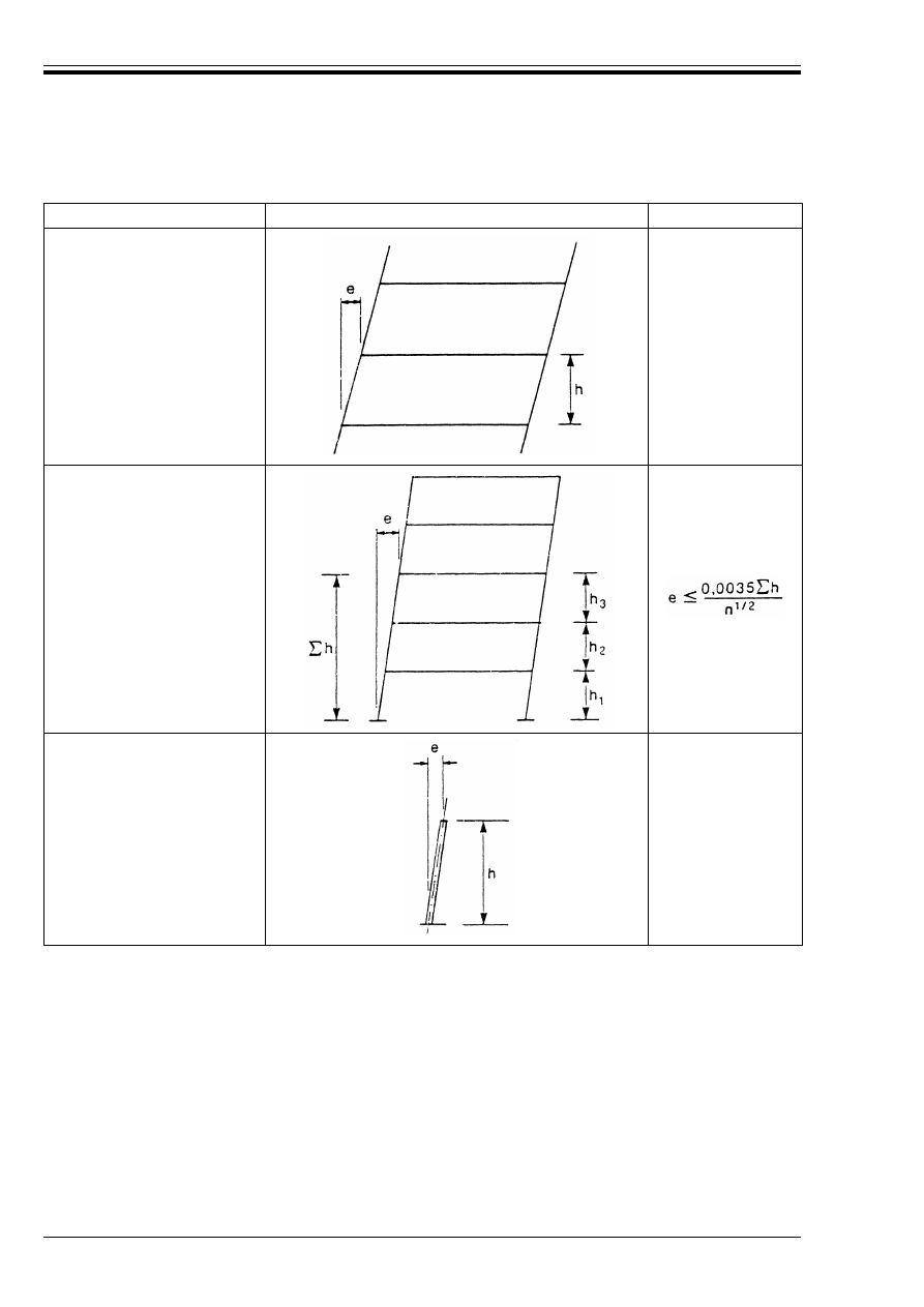
ENV 1993-1-1:1992
160
© BSI 04-2000
Criterion
Description
Permitted deviation
Inclination of a column
between adjacent floor levels
e k 0,002h
Location of a column
at any floor level, from
a vertical line through
the intended location
of the column base
Inclination of a column
in a single-storey
building, without a
crane gantry, other than
in a portal frame
e k 0,0035h
Figure 7.2.1 — Normal tolerances after erection — Part 1
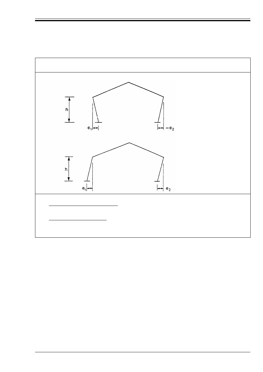
ENV 1993-1-1:1992
© BSI 04-2000
161
7.7.4 Fabrication tolerances
(1) The normal fabrication tolerances shall be the normal fabrication tolerances for building structures
specified in Reference Standard 6.
(2) The straightness tolerances specified in Table 7.2 have been assumed in the derivation of the design
rules for the relevant type of member. Where the curvature exceeds these values, the additional curvature
shall be allowed for in the design calculations.
Criterion:
Inclination of columns of a portal frame
not supporting a crane gantry.
Description:
Permitted deviation:
Inclination of individual columns:
e
1
k 0,010h : e
2
k 0,010h
Mean inclination of a frame:
k 0,002h where e
1
U e
2
Figure 7.2.2 — Normal tolerances after erection — Part 2
e
1
e
2
+
2
------------------

ENV 1993-1-1:1992
162
© BSI 04-2000
Table 7.2 — Straightness tolerances incorporated in design rules
7.7.5 Position of holding down bolts
(T olerances shall be specified for the positional deviations of the holding down bolts which will enable the
tolerance limits for erection of steelwork to be satisfied.
(2) Tolerances shall be specified for the levels of the holding down bolts which enable the specified
tolerances to be satisfied for the following criteria:
• the level of the baseplate
• the thickness of the bedding material under the baseplate
• the protrusion of the bolt through the nut
• the number of threads clear below the nut.
(3) The deviations of the spacings between individual bolts within the group of holding down bolts for each
member shall not exceed the following:
7.8 Inspection and testing
(1) The requirements for inspection and testing shall be those for the normal level of inspection and testing
specified in the relevant Reference Standards, unless special inspection requirements are specified.
(2) The criteria for acceptance shall be the normal criteria for acceptance specified in the relevant Reference
Standards, unless special acceptance criteria are specified.
8 Design assisted by testing
8.1 Basis
(1) The provisions in this Chapter give guidance to designers who may become involved with experimental
assessments.
(2) When the calculation models available are not sufficient for a particular structure or structural
component, experimental assessment shall be undertaken in place of design by calculation or to
supplement design by calculation.
(3) Experimental verification may also be undertaken where the rules for design by calculation given in
this Eurocode would lead to uneconomic results. However, the conservative assumptions in the specified
calculation models (which are intended to account for unfavourable calculation influences not explicitly
considered in the specified calculation models) shall not be by-passed.
(4) The planning, execution, evaluation and documentation of tests shall be in accordance with the
minimum requirements stated in this Chapter.
(5) Because circumstances and test facilities vary greatly, the test procedures should be agreed in advance
by all concerned.
Criterion
Permitted deviation
Straightness of a column (or other compression
member) between points which will be laterally
restrained on completion of erection
± 0,001L
± 0,002L
generally
for members with hollow
cross-sections
where L is the length between points which will be
laterally restrained
Straightness of the compression flange of a
beam, relative to the weak axis, between points
which will be laterally restrained on
completion of erection
± 0,001L
± 0,002L
generally
for members with hollow
cross-sections
where L is the length between points which will be
laterally restrained
w
for bolts rigidly cast in, between centres of bolts:
± 5 mm
w
for bolts set in sleeves, between centres of sleeves: ± 10 mm.

ENV 1993-1-1:1992
© BSI 04-2000
163
8.2 Planning of tests
(1) The experimental assessment shall be based on tentative calculation models, which may be incomplete,
but which relate one or several relevant variables to the structural behaviour under consideration, such
that basic tendencies are adequately predicted. The experimental assessment shall then be confined to the
evaluation of correction terms in the tentative calculation model.
(2) If the prediction of the relevant calculation models or of the failure mode to be expected in the tests is
extremely doubtful, the test plan shall be developed on the basis of accompanying pilot tests.
(3) Prior to the execution of tests, a test plan shall be drawn up by the designer and the testing organisation.
This shall contain the objective of the tests and all the instructions and other specifications necessary for
the selection or production of the test specimens, the execution of the tests and the test evaluation.
(4) Reference should be made to informative Annex Y for guidance in preparing the test plan.
(5) The test plan shall deal with the following items:
a) Scope of information required from the tests (e.g. required parameters and range of validity).
b) Description of all properties of the members considered which may influence the behaviour at a limit
state, (e.g. form of the member, stiffness, steel grade and quality and relevant material properties,
geometrical and structural parameters and their tolerances, parameters influenced by fabrication and
erection procedures).
c) Specifications on the properties of the test specimen (e.g. sampling procedures, specification for
dimensions, material and fabrication of prototypes, number of specimens, number of subsets,
restraints).
d) Description of the actions to which the members are required to react and demonstrate the
properties referred to in b), (e.g. load arrangements, load cases, load combinations).
e) Specifications on the loading and environmental conditions in the test (e.g. loading points, loading
methods, loading path in time and space, temperatures).
f) Modes of failure and tentative calculation models with the corresponding relevant variables,
see 8.2(1).
g) Testing arrangements (including measures to ensure sufficient strength and stiffness of the loading
and supporting rigs and clearance for deflections etc).
h) Determination of the monitoring points and methods for observation and recording (e.g. time
histories of strains, forces, deflections).
i) Determination of the type and control of load application (stress-controlled, strain-controlled etc).
k) Required accuracy of measurements and measuring devices.
(6) All details on the sampling or manufacturing of the test specimens shall be reported and measurements
shall be carried out on these test specimen before the execution of tests starts, in order to demonstrate that
the test plan has been fulfilled, otherwise it shall be revised.
8.3 Execution of tests
(1) The performance of experimental assessments shall be entrusted only to organisations where the staff
is sufficiently knowledgeable and experienced in the planning, execution and evaluation of tests.
(2) The testing laboratory shall be adequately equipped and the testing organisation shall ensure careful
management and documentation of all tests.
8.4 Test evaluation
(1) The test evaluation shall take account of the random character of all data.
(2) This test evaluation should be carried out using the method given in Annex Z
21)
).
21)
To be prepared at a later stage
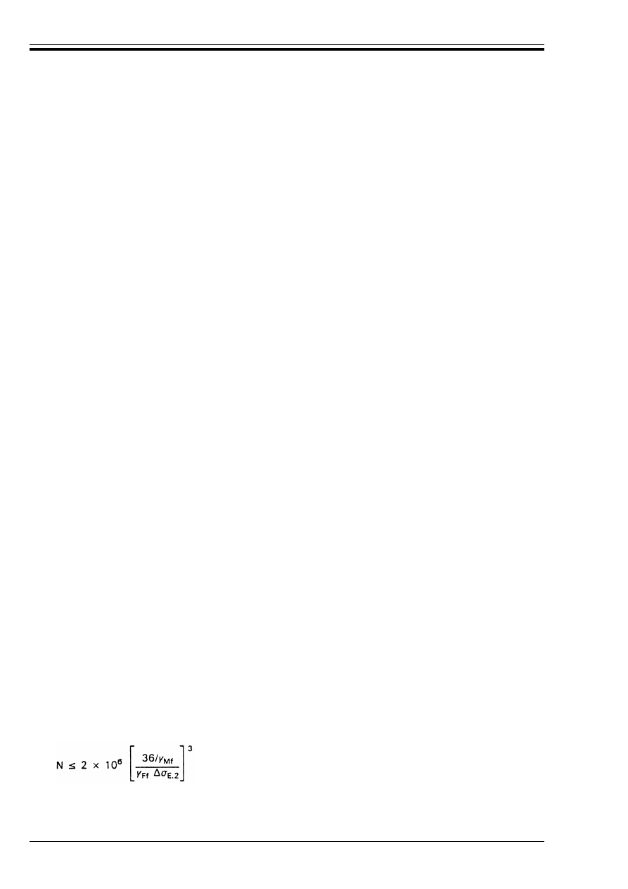
ENV 1993-1-1:1992
164
© BSI 04-2000
8.5 Documentation
(1) The following documentation shall be provided in the test report:
• the test plan (including any revisions),
• descriptions and specifications for all test specimens,
• details of the testing arrangements,
• details of the execution of the tests, and
• the test results which are necessary for the test evaluation.
9 Fatigue
9.1 General
9.1.1 Basis
(1) The aim of designing a structure against the limit state of fatigue is to ensure, with an acceptable level
of probability, that its performance is satisfactory during its entire design life, such that the structure is
unlikely to fail by fatigue or to require repair of damage caused by fatigue.
(2) The required safety level shall be obtained by applying the appropriate partial safety factors (see 9.3).
9.1.2 Scope
(1) This Chapter presents a general method for the fatigue assessment of structures and structural
elements which are subjected to repeated fluctuations of stresses.
(2) The fatigue assessment procedures assume that the structure also conforms with the other limit state
requirements of this Eurocode.
(3) The fatigue assessment procedures given in this Chapter are applicable when all structural steel
materials, fasteners and welding consumables conform with the requirements specified in Chapter 3.
9.1.3 Limitations
(1) For fatigue assessment, all nominal stresses [see 9.1.5(7)] shall be within the elastic limits of the
material. The range of the design values of such stresses shall not exceed 1,5 f
y
for normal stresses
or 1,5 f
y
/Æ3 for shear stresses.
(2) The fatigue strengths specified in this Chapter are applicable to structures with suitable corrosion
protection, subjected only to mildly corrosive environments, such as normal atmospheric conditions
(pit depth k 1 mm).
(3) The fatigue assessment procedures given in this Chapter are applicable only to structures subjected to
temperatures not exceeding 150 °C.
9.1.4 Necessity for fatigue assessment
(1) No fatigue assessment is normally required for building structures except as follows:
a) Members supporting lifting appliances or rolling loads.
b) Members subject to repeated stress cycles from vibrating machinery.
c) Members subject to wind-induced oscillations.
d) Members subject to crowd-induced oscillations.
(2) No fatigue assessment is required when any of the following conditions is satisfied:
a) The largest nominal stress range %B satisfies:
b) The total number of stress cycles N satisfies:
¾
Ff
%B
k 26/¾
Mf
N/mm
2
.
(9.1)
(9.2)
where %B
E.2
is the equivalent constant amplitude stress range in N/mm
2
.

ENV 1993-1-1:1992
© BSI 04-2000
165
c) For a detail for which a constant amplitude fatigue limit %B
D
is specified, the largest stress range
(nominal or geometric as appropriate) %B satisfies:
9.1.5 Definitions
(1) Fatigue: Damage in a structural part, through gradual crack propogation caused by repeated stress
fluctuations.
(2) Fatigue loading: A set of typical load events described by the positions of loads, their intensities and
their relative frequencies of occurrence.
(3) Loading event: A defined loading sequence applied to the structure and giving rise to a stress history.
(4) Equivalent constant amplitude fatigue loading: Simplified constant amplitude loading
representing the fatigue effects of actual variable amplitude loading events.
(5) Stress history: A record, or a calculation, of the stress variation at a particular point in a structure
during a load event.
(6) Stress range: The algebraic difference between the two extremes of a particular stress cycle forming
part of a stress history. (%B = B
max
– B
min
or %Ù = Ù
max
– Ù
min
).
(7) Nominal stress: A stress in the parent material adjacent to a potential crack location, calculated in
accordance with simple elastic strength of materials theory, excluding all stress concentration effects.
(8) Modified nominal stress: A nominal stress increased by an appropriate stress concentration factor,
to allow for a geometric discontinuity which has not been taken into account in the classification of a
particular constructional detail.
(9) Geometric stress: The maximum principal stress in the parent material, adjacent to the weld toe,
taking into account stress concentration effects due to the overall geometry of a particular constructional
detail, but excluding local stress concentration effects due to weld geometry and discontinuities in the weld
and the adjacent parent metal.
NOTE The geometric stress is also known as the “hot spot stress”.
(10) “Rainflow” method and “reservoir” method: Particular methods of producing a stress-range
spectrum from a given stress history.
NOTE They are two versions of the same basic method.
(11) Stress-range spectrum: Histogram of the frequency of occurrence for all stress ranges of different
magnitudes recorded or calculated for a particular loading event.
(12) Design spectrum: The total of all stress-range spectra relevant to the fatigue assessment,
see Figure 9.1.1.
(13) Equivalent constant amplitude stress range: The constant-amplitude stress range that would
result in the same fatigue life as for the spectrum of variable-amplitude stress ranges, when the comparison
is based on a Miner’s summation.
(14) For convenience, the equivalent constant amplitude stress range may be related to a total number
of 2 million variable amplitude stress range cycles.
(15) Fatigue life: The total number of cycles of stress variation predicted to cause fatigue failure.
(16) Miner’s summation: A linear cumulative damage calculation based on the Palmgren-Miner rule.
(17) Constant amplitude fatigue limit: The limiting stress range value above which a fatigue
assessment is necessary.
(18) Detail category: The designation given to a particular welded or bolted detail, in order to indicate
which fatigue strength curve is applicable for the fatigue assessment.
(19) Fatigue strength curve: The quantitative relationship relating fatigue failure to stress range and
number of stress cycles, used for the fatigue assessment of a category of constructional detail,
see Figure 9.1.2.
(20) Design life: The reference period of time for which a structure is required to perform safely with an
acceptable probability that failure by fatigue cracking will not occur.
(21) Cut-off limit: Limit below which stress ranges of the design spectrum do not contribute to the
calculated cumulative damage.
¾
Ff
%B
k%B
D
/¾
Mf
(9.3)
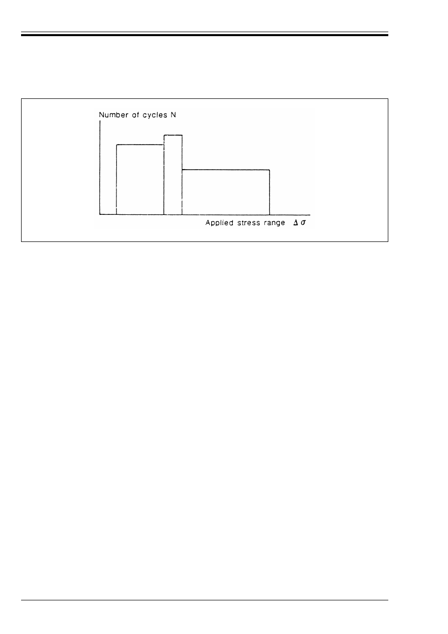
ENV 1993-1-1:1992
166
© BSI 04-2000
Figure 9.1.1 — Design spectrum
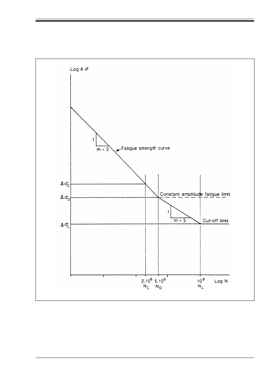
ENV 1993-1-1:1992
© BSI 04-2000
167
Figure 9.1.2 — Fatigue strength curve

ENV 1993-1-1:1992
168
© BSI 04-2000
9.1.6 Symbols
9.2 Fatigue loading
(1) The fatigue loading shall be obtained from ENV 1991 Eurocode 1
22)
or other relevant loading standard.
(2) The loading used for the fatigue assessment shall be a characteristic value which represents the
anticipated service loading throughout the required design life of the structure with a sufficient, defined,
reliability.
(3) The fatigue loading may comprise different loading events which are defined by complete loading
sequences of the structure, each characterised by their relative frequency of occurrence as well as their
magnitude and geometrical position.
(4) Dynamic effects shall be considered when the response of the structure contributes to the modification
of the design spectrum.
(5) In the absence of more accurate information, the dynamic amplification factors used for the static limit
state may be employed.
(6) The effect of a loading event shall be represented by its stress history, see 9.1.5(5).
(7) The load models used for fatigue assessment of such structures as bridges and cranes should take into
account the possible changes in use, such as growth of traffic or changes in the loading rate.
(8) Allowance should also be made for such future changes where it is necessary to base a fatigue assessment
on a measured stress history.
(9) Simplified design calculations may be based on an equivalent fatigue loading, representing the fatigue
effects of the full spectrum of loading events.
(10) The equivalent fatigue loading may vary with the dimensions and location of the structural element.
¾
Ff
Partial safety factor for fatigue loads.
¾
Mf
Partial safety factor for fatigue strength.
B
max
, B
min
Maximum and minimum values of the fluctuating stresses in a stress cycle.
%B
Nominal stress range (normal stress).
%B
D
Constant amplitude fatigue limit.
%B
R
Fatigue strength (normal stress).
%B
C
Reference value of the fatigue strength at 2 million cycles (normal stress).
%B
E
Equivalent constant amplitude stress range (normal stress).
%B
E.2
Equivalent constant amplitude stress range (normal stress) for 2 million cycles.
%B
L
Cut-off limit.
%Ù
Nominal stress range (shear stress).
%Ù
R
Fatique strength (shear stress).
%Ù
E
Equivalent constant amplitude stress range (shear stress).
%Ù
E.2
Equivalent constant amplitude stress range (shear stress) for 2 million cycles.
%Ù
C
Reference value of the fatigue strength at 2 million cycles (shear stress).
m
Slope constant of a fatigue strength curve, with values of 3 and/or 5.
n
i
Number of cycles of stress range %B
i
.
N
Number (or total number) of stress range cycles.
N
i
Number of cycles of stress range ¾
Ff
¾
Mf
%B
i
to cause failure.
N
C
Number of cycles (2 million) at which the reference value of the fatigue strength is defined.
N
D
Number of cycles (5 million) at which the constant amplitude fatigue limit is defined.
N
L
Number of cycles (100 million) at which the cut-off limit is defined.
log
Logarithm to base 10.
22)
In preparation

ENV 1993-1-1:1992
© BSI 04-2000
169
9.3 Partial safety factors
9.3.1 General
(1) The values of the partial safety factors to be used shall be agreed between the client, the designer and
competent public authority as being appropriate, considering:
• the ease of access for inspection or repair and likely frequency of inspection and maintenance,
• the consequences of failure.
(2) Inspection may detect fatigue cracks before subsequent damage is caused. Such inspection is visual
unless specified otherwise in the Project Specification.
NOTE In-service inspection is not a requirement of Eurocode 3-1.1 and, if it is required, it should be subject to agreement.
(3) In any circumstances, the possibility of general failure without any pre-warning conditions is not
tolerable.
(4) Difficulties of access for inspection or repair may be such as to make the detection or the repair of cracks
impractical. The client should be made aware of this so that measures to perform inspection may be taken.
9.3.2 Partial safety factors for fatigue loading
(1) To take account of uncertainties in the fatigue response analysis, the design stress ranges for the fatigue
assessment procedure shall incorporate a partial safety factor ¾
Ff
.
(2) The partial safety factor ¾
Ff
covers the uncertainties in estimating:
• the applied load levels,
• the conversion of these loads into stresses and stress ranges,
• the equivalent constant amplitude stress range from the design stress range spectrum,
• the design life of the structure, and the evolution of the fatigue loading within the required design life
of the structure.
(3) The fatigue loading given in ENV 1991 Eurocode 1
23)
already incorporates an appropriate value of the
partial safety factor ¾
Ff
.
Unless otherwise stated in subsequent Parts of Eurocode 3, or in the relevant loading standard, a value
of may be applied to the fatigue loading.
9.3.3 Partial safety factors for fatigue strength
(1) In the fatigue assessment procedure, in order to take account of uncertainties in the fatigue resistance,
the design value of the fatigue strength shall be obtained by dividing by a partial safety factor ¾
Mf
.
(2) The factor ¾
Mf
covers the uncertainties of the effects of:
• the size of the detail,
• the dimensions, shape and proximity of the discontinuities,
• local stress concentrations due to welding uncertainties.
• variable welding processes and metallurgical effects.
9.3.4 Recommended values of ¾
Mf
(1) The recommended values given in this clause assume that Quality Assurance procedures are applied to
ensure that the fabricated constructional details comply with the relevant quality requirements for
structures subjected to fatigue as defined in Reference Standard 9, see normative Annex B.
(2) Concerning the consequences of failure, two possible situations may arise as follows:
• “fail-safe” structural components with reduced consequences of failure, such that the local failure of
one component does not result in failure of the structure.
• non “fail-safe” structural components where local failure of one component leads rapidly to failure of
the structure.
(3) Recommended values of the partial safety factor ¾
Mf
are given in Table 9.3.1. These values should be
applied to the fatigue strength.
23)
In preparation
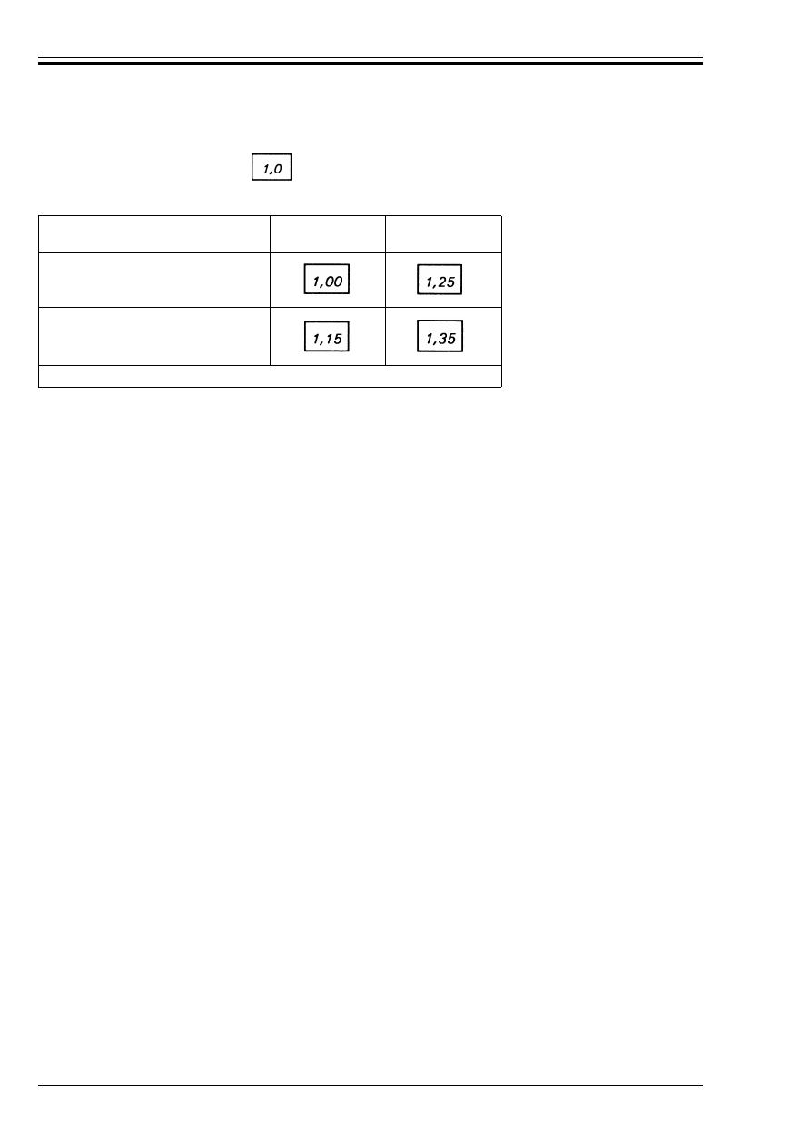
ENV 1993-1-1:1992
170
© BSI 04-2000
(4) Where values of ¾
Ff
other than are applied to the fatigue loading, the ¾
Mf
values may need
corresponding adjustment.
Table 9.3.1 — Partial safety factor for fatigue strength ¾
Mf
9.4 Fatigue stress spectra
9.4.1 Calculation of stresses
(1) Stresses shall be determined by an elastic analysis of the structure under fatigue loading. Dynamic
response of the structure or impact effect shall be considered when appropriate.
9.4.2 Stress range in parent material
(1) Depending upon the fatigue assessment carried out, either nominal stress ranges or geometric stress
ranges shall be evaluated.
(2) When determining the stress at a detail, stresses arising from joint eccentricity and imposed
deformations, secondary stresses due to joint stiffness, stress redistribution due to buckling and shear lag,
and the effects of prying (see Chapter 6) shall be taken into account.
9.4.3 Stress range for welds
(1) In load-carrying partial penetration or fillet welded joints, the forces transmitted by a unit length of
weld shall be resolved into components transverse and parallel to the longitudinal axis of the weld.
(2) The fatigue stresses in the weld shall be taken as:
• a normal stress B
w
transverse to the axis of the weld
• a shear stress Ù
w
longitudinal to the axis of the weld.
(3) The stresses B
w
and Ù
w
may be obtained by dividing the relevant component of the force transmitted per
unit length of weld, by the throat size a.
(4) Alternatively B
w
and Ù
w
may be obtained by using the method given in normative Annex M and taking:
9.4.4 Design stress range spectrum
(1) The stress history due to a loading event shall be reduced to a stress range spectrum by employing a
soundly based method of cycle counting.
(2) For a particular detail, the total of all stress range spectra, caused by all loading events, shall be
compiled to produce the design stress range spectrum to be used for the fatigue assessment.
(3) The design stress range spectrum for a typical detail or structural element may be derived from the stress
history obtained by appropriate tests or by numerical evaluations based on the theory of elasticity.
(4) For many applications the “rainflow” or “reservoir” stress cycle counting methods are appropriate for use
in conjunction with the Palmgren-Miner summation.
(5) Different components of a structure may have different stress range spectra.
Inspection and access
“Fail-safe”
components
Non “fail-safe”
components
Periodic inspection
and maintenance.
Accessible joint detail.
Periodic inspection
and maintenance.
Poor accessibility.
See
9.3.1
(2) concerning inspection.
B
w
= [B
8
2
+ Ù
8
2
]
0,5
and
Ù
w
= Ù
(9.4)
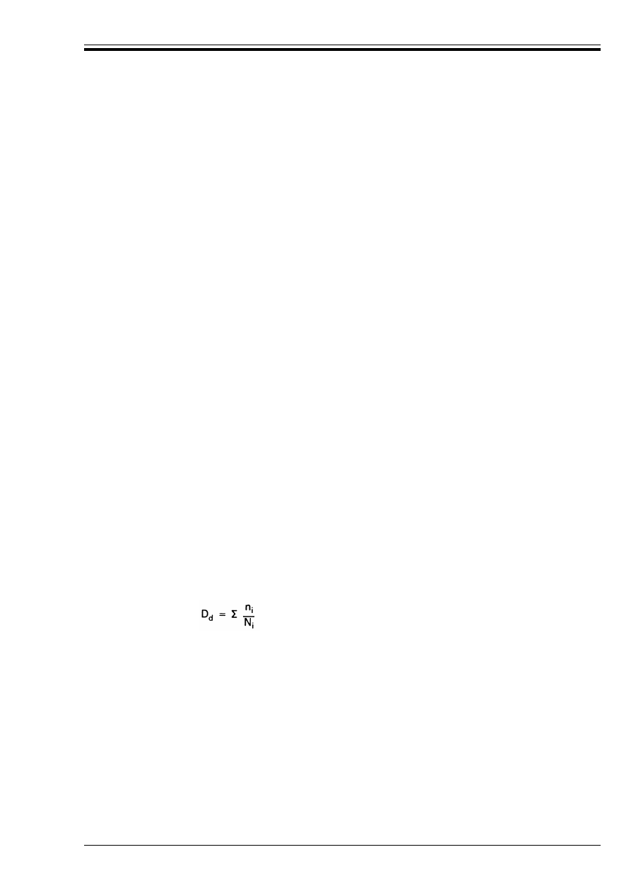
ENV 1993-1-1:1992
© BSI 04-2000
171
9.5 Fatigue assessment procedures
9.5.1 General
(1) The safety verification shall be carried out either:
• in terms of cumulative damage by comparing the applied damage to the limiting damage, or
• in terms of the equivalent stress range by comparing it with the fatigue strength for a given number
of stress cycles.
(2) For a particular class of constructional detail, the stresses to be considered may be normal stresses or
shear stresses or both.
(3) When a constructional detail is defined in the detail classification tables (Table 9.8.1 to Table 9.8.7) the
nominal stress range shall be used, see 9.5.2.
(4) The effects of geometric discontinuities which are not part of the constructional detail itself, such as
holes, cut-outs or re-entrant corners shall be taken into account separately, either by a special analysis or
by the use of appropriate stress concentration factors, to determine the modified nominal stress range.
(5) When a constructional detail differs from a detail defined in the detail classification tables by the
presence of a geometric discontinuity in the detail itself, the geometric stress range shall be used, see 9.5.3.
(6) For constructional details not included in the detail classification tables, the geometric stress range
shall be used, see 9.5.3.
9.5.2 Fatigue assessment based on nominal stress ranges
9.5.2.1 Constant amplitude loading
(1) For constant amplitude loading the fatigue assessment criterion is:
9.5.2.2 Variable amplitude loading
(1) For variable amplitude loading defined by a design spectrum, the fatigue assessment shall be based on
Palmgren-Miner rule of cumulative damage.
(2) If the maximum stress range due to the variable amplitude loading is higher than the constant
amplitude fatigue limit then one of the following types of fatigue assessment shall be made:
a) Cumulative damage, see (3).
b) Equivalent constant amplitude, see (7).
(3) A cumulative damage assessment may be made using:
(4) Cumulative damage calculations shall be based on one of the following:
a) a fatigue strength curve with a single slope constant m = 3,
b) a fatigue strength curve with double slope constants (m = 3 and m = 5), changing at the constant
amplitude fatigue limit.
c) a fatigue strength curve with double slope constants (m = 3 and m = 5), and a cut-off limit at
N = 100 million cycles,
d) in the case described in 9.6.2.2(2), a fatigue strength curve with a single slope constant m = 5 and a
cut-off limit at N = 100 million cycles.
(5) C ase c) is the most general. Stress ranges below the cut-off limit may be neglected.
¾
Ff
%B
k%B
R
/¾
Mf
(9.5)
where %B
is the nominal stress range
and
%B
R
is the fatigue strength for the relevant detail category (see 9.8) for the total number of
stress cycles N during the required design life.
D
d
k1
where
(9.6)
in which
n
i
is the number of cycles of stress range %B
i
during the required design life
N
i
is the number of cycles of stress range ¾
Ff
¾
Mf
%B
i
to cause failure, for the relevant detail
category, see 9.8.
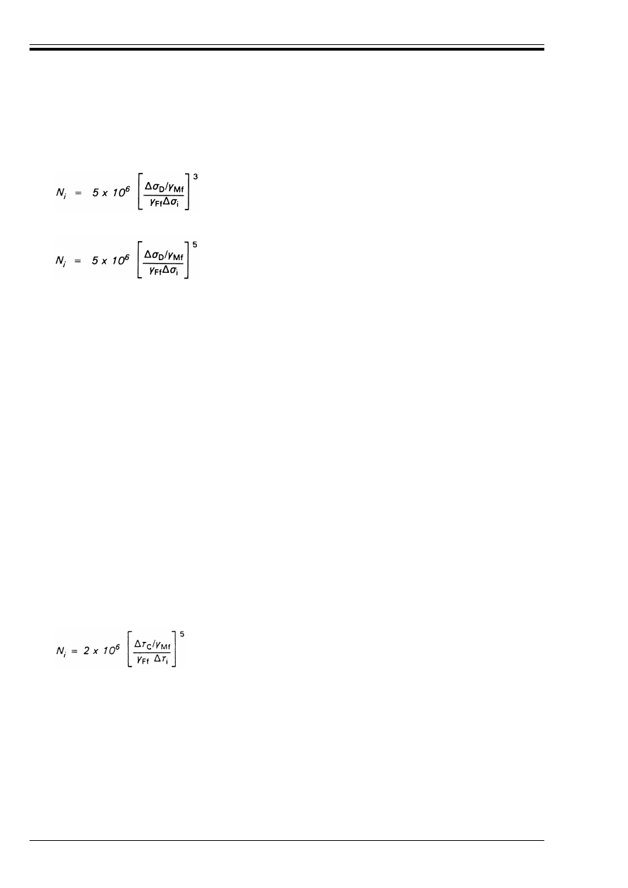
ENV 1993-1-1:1992
172
© BSI 04-2000
(6) When using case c) with a constant amplitude fatigue limit %B
D
at 5 million cycles, N
i
may be calculated
as follows:
(7) An equivalent constant amplitude fatigue assessment may be made by checking the criterion:
(8) A conservative assumption may be adopted in evaluating %B
E
and %B
R
by using a fatigue strength curve
of unique slope constant m = 3.
(9) More generally, %B
E
may be calculated taking into account the double slope fatigue strength curve and
the cut-off limit, as defined in Figure 9.1.2.
(10) Alternatively, an equivalent constant amplitude fatigue assessment may be made by checking the
specific criterion:
9.5.2.3 Shear stress ranges
(1) Nominal shear stress ranges, %
Ù
, shall be treated similarly to nominal normal stress ranges, but using
a single slope constant m = 5.
(2) For shear stresses, N
i
may be calculated as follows:
9.5.2.4 Combination of normal and shear stress ranges
(1) In the case of a combination of normal and shear stresses the fatigue assessment shall consider their
combined effects.
(2) If the equivalent nominal shear stress range is less than 15 % of the equivalent nominal normal stress
range, the effects of the shear stress range may be neglected.
(3) At locations other than weld throats, if the normal and shear stresses induced by the same loading event
vary simultaneously, or if the plane of the maximum principal stress does not change significantly in the
course of a loading event, the maximum principal stress range may be used.
w
if ¾
Ff
%B
i
U%B
D
/¾
Mf
:
(9.7)
w
if %B
D
/¾
Mf
> ¾
Ff
%B
i
U%B
L
/¾
Mf
:
(9.8)
w
¾
Ff
mn %B
i
<%B
L
/¾
Mf
:
N
i
= Z
(9.9)
¾
Ff
%B
E
k%B
R
/¾
Mf
(9.10)
where %B
E
is the equivalent constant amplitude stress range which, for the given number of cycles,
leads to the same cumulative damage as the design spectrum.
and
%B
R
is the fatigue strength for the relevant detail category (see 9.8), for the same number of
cycles as used to determine %B
E
.
¾
Ff
%B
E.2
k%B
C
/¾
Mf
(9.11)
where %B
E.2
is the equivalent constant amplitude stress range for 2 million cycles, and
%B
C
is the reference value of the fatigue strength at 2 million cycles for the relevant detail
category, see 9.8.
w
if ¾
Ff
%Ù
i
U%Ù
L
/¾
Mf
:
(9.12)
w
if ¾
Ff
%Ù
i
<%Ù
L
/¾
Mf
:
N
i
= Z
(9.13)
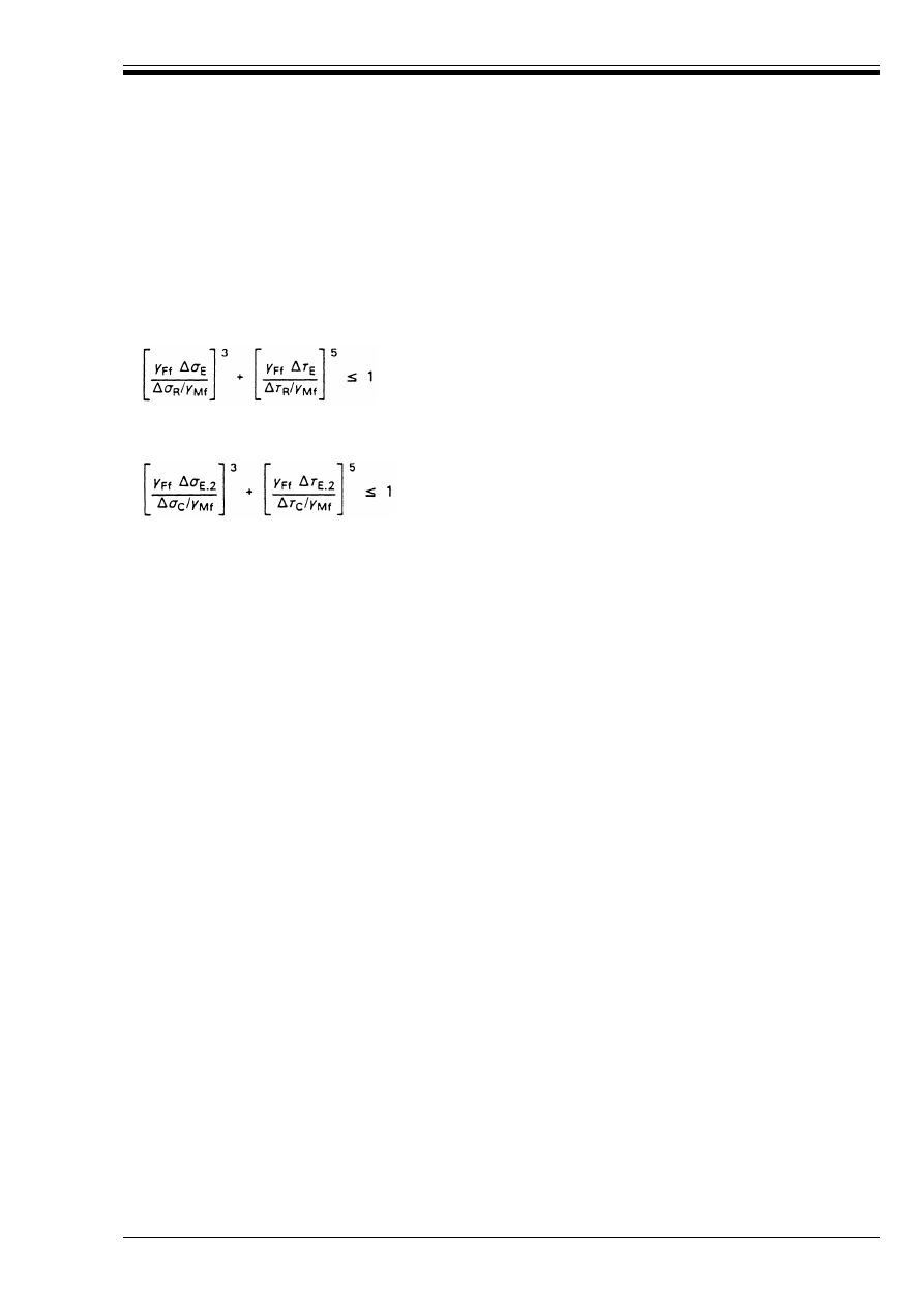
ENV 1993-1-1:1992
© BSI 04-2000
173
(4) If, at the same location, normal and shear stresses vary independently, the components of damage for
normal and shear stresses shall be assessed separately using the Palmgren-Miner rule, then combined
using the criterion:
(5) When using equivalent constant amplitude stress ranges, this criterion generally becomes:
(5) Alternatively, an equivalent constant amplitude fatigue assessment may be made using the specific
criterion:
(6) Stress ranges in welds shall be determined as specified in 9.4.3. The components of damage for normal
and shear stresses shall be assessed separately using the Palmgren-Miner rule, then combined using the
criterion:
9.5.3 Fatigue assessments based on geometric stress ranges
(1) The geometric stress is the maximum principal stress in the parent material adjacent to the weld toe
taking into account only the overall geometry of the joint, excluding local stress concentration effects due
to the weld geometry and discontinuities at the weld toe.
(2) The maximum value of the geometric stress range shall be found, investigating various locations at the
weld toe around the welded joint or the stress concentration area.
(3) The geometric stresses may be determined using stress concentration factors obtained from parametric
formulae within their domains of validity, a finite element analysis or an experimental model.
(4) A fatigue assessment based on the geometric stress range, shall be treated similarly to the assessments
given in 9.5.2, but replacing the nominal stress range by the geometric stress range.
(5) The fatigue strength to be used in assessments based on geometric stress ranges shall be determined
by reference to 9.6.3.
9.6 Fatigue strength
9.6.1 General
(1) The fatigue strength is defined for normal stresses by a series of log %B
R
– log N curves, each applying
to a typical detail category. Each detail category is designated by a number which represents, in N/mm
2
,
the reference value %B
C
of the fatigue strength at 2 million cycles, see Figure 9.6.1. The values used are
rounded values, corresponding to the detail categories given in Table 9.6.1.
(2) The fatigue strength curves for nominal normal stresses are defined by:
D
d.
B
+ D
d.
Ù
k 1
(9.14)
in which D
d.
B
= C(n
i
/N
i
) for normal stress ranges %B
i
and
D
d.
Ù
= C(n
i
/N
i
) for shear stress ranges %T
i
(9.15)
(9.16)
D
d.
B
+ D
d.
Ù
k1
(9.17)
in which D
d.
B
= C(n
i
/N
i
) for stress ranges of the normal stress B
w
defined in 9.4.3.
and
D
d.
Ù
= C(n
i
/N
i
) for stress ranges of the shear stress Ù
w
defined in 9.4.3.
log N = log a – m log %B
R
(9.18)
where
%B
R
is the fatigue strength
N
is the number of stress range cycles
m
is the slope constant of the fatigue strength curves, with values of 3 and/or 5.
log a is a constant which depends on the related part of the slope, see 9.6.2.1.

ENV 1993-1-1:1992
174
© BSI 04-2000
(3) Similar fatigue strength curves are used for shear stresses, see Figure 9.6.2 and Table 9.6.2.
(4) The curves are based on representative experimental investigations and thus include the effects of:
• local stress concentrations due to the weld geometry,
• size and shape of acceptable discontinuities,
• the stress direction,
• residual stresses,
• metallurgical conditions,
• in some cases, the welding process and post-weld improvement procedures.
(5) When test data are used to determine the appropriate detail category for a particular constructional
detail, the value of the stress range %B
R
corresponding to a value of N of 2 million cycles shall be calculated
for a 75 % confidence interval of 95 % probability of survival for log N, taking into account the standard
deviation and the sample size. The number of data points (not lower than 10) shall be considered in the
statistical analysis.
(6) Proper account shall be taken of the fact that residual stresses are low in small scale samples. The
resulting fatigue strength curve shall be corrected to allow for the greater effect of residual stresses in full
scale structures.
(7) The level of acceptable discontinuities are defined in Reference Standard 9, see normative Annex B.
(8) Separate fatigue strength curve definitions are given for:
• Classified details, for which the nominal stress range procedure applies, see 9.6.2.
• Non-classified details, for which the geometrical stress range procedure applies, see 9.6.3.
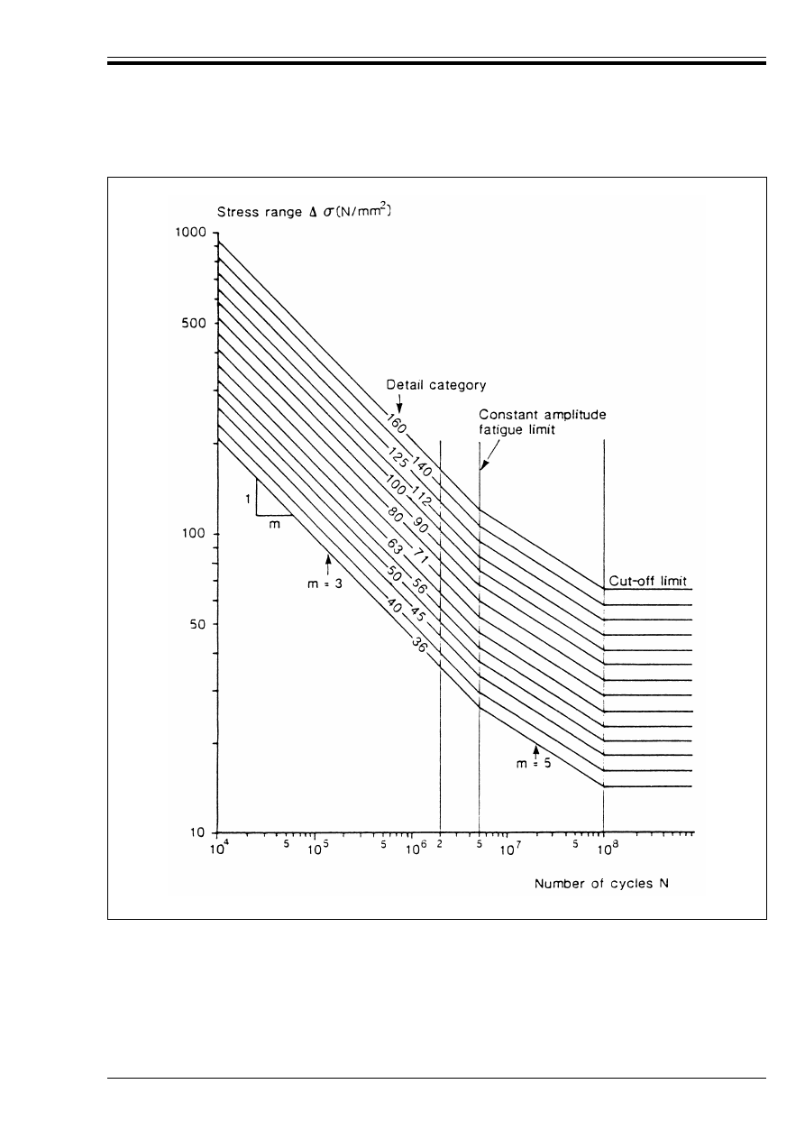
ENV 1993-1-1:1992
© BSI 04-2000
175
Figure 9.6.1 — Fatigue strength curves for normal stress ranges
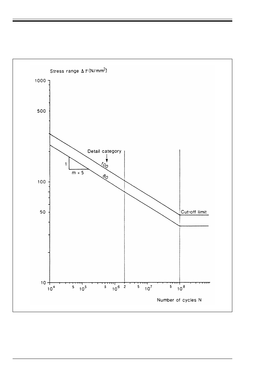
ENV 1993-1-1:1992
176
© BSI 04-2000
9.6.2 Fatigue strength curves for classified details
9.6.2.1 Fatigue strength curves for open sections
(1) The detail categories to be used for various typical constructional details for open sections are given in 5
tables as follows:
Table 9.8.1: Non-welded details.
Table 9.8.2: Welded built-up sections.
Figure 9.6.2 — Fatigue strength curves for shear stress ranges
ENV 1993-1-1:1992
© BSI 04-2000
177
Table 9.8.3: Transverse butt welds.
Table 9.8.4: Welded attachments with non-load carrying welds.
Table 9.8.5: Welded joints with load-carrying welds.
(2) In Table 9.8.1 onwards, the arrows in the diagrams indicate the location and direction of the stresses to
which the relevant fatigue strengths apply.
(3) The detail category used to designate a particular fatigue strength curve corresponds to the reference
value (in N/mm
2
) of the fatigue strength at 2 million cycles, %B
C
or %Ù
C
as appropriate.
(4) Fatigue strength curves for nominal normal stress ranges for a number of typical detail categories are
given in Figure 9.6.1. The constant amplitude fatigue limit corresponds to the fatigue strength for 5 million
cycles and the cut-off limit corresponds to the fatigue strength for 100 million cycles.
(5) The corresponding values for calculating the fatigue strength are given in Table 9.6.1.
Table 9.6.1 — Numerical values for fatigue strength curves
for normal stress ranges
(6) Fatigue strength curves for nominal shear stress ranges are given in Figure 9.6.2. They have a single
slope constant of m = 5. There is no constant amplitude fatigue limit for these curves but the cut-off limit
at 100 million cycles applies as for nominal normal stress ranges.
(7) The corresponding values for calculating the fatigue strength are given in Table 9.6.2.
(8) Detail category 100 is for parent metal, full penetration butt welds and for bearing type fitted bolts in
shear.
(9) Detail category 80 is for fillet welds and for partial penetration butt welds in shear.
Table 9.6.2 — Numerical values for fatigue
strength curves for shear stress ranges
9.6.2.2 Fatigue strength curves for hollow sections
(1) The fatigue strength curves to be used in conjunction with the hollow section details shown in
Table 9.8.6, are those given in Figure 9.6.1. They have double slope constants of m = 3 and m = 5.
Detail
category
log a for N < 10
8
Stress range at
constant amplitude
fatigue limit
Stress range at
cut-off limit
N k 5 × 10
6
N U 5 × 10
6
(N = 5 × 10
6
)
(N = 10
8
)
%B
C
(N/mm
2
)
(m = 3)
(m = 5)
%B
D
(N/mm
2
)
%B
L
(N/mm
2
)
160
140
125
112
100
90
80
71
63
56
50
45
40
36
12,901
12,751
12,601
12,451
12,301
12,151
12,001
11,851
11,701
11,551
11,401
11,251
11,101
10,951
17,036
16,786
16,536
16,286
16,036
15,786
15,536
15,286
15,036
14,786
14,536
14,286
14,036
13,786
117
104
93
83
74
66
59
52
46
41
37
33
29
26
64
57
51
45
40
36
32
29
26
23
20
18
16
14
Detail
category
%Ù
C
(N/mm
2
)
log a for N < 10
8
(m = 5)
Stress range at cut-off
limit (N = 10
8
)
%Ù
L
(N/mm
2
)
100
80
16,301
15,801
46
36
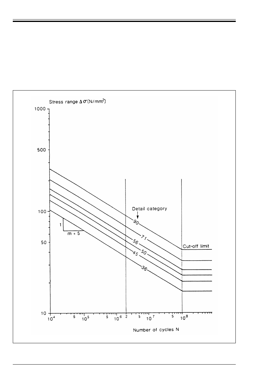
ENV 1993-1-1:1992
178
© BSI 04-2000
(2) The fatigue strength curves to be used in conjunction with the hollow section joint details for lattice
girders shown in Table 9.8.7, are given in Figure 9.6.3. They have a single slope constant of m = 5.
(3) The corresponding values for numerical calculations of the fatigue strength are given in Table 9.6.3.
(4) The throat thickness of a fillet weld shall not be less than the wall thickness of the hollow section
member which it connects.
Figure 9.6.3 — Fatigue strength curves for joints in tubular lattice girders
ENV 1993-1-1:1992
© BSI 04-2000
179
Table 9.6.3 — Numerical values for fatigue
strength curves for hollow sections
(5) The member forces may be analysed neglecting the effect of eccentricities and joint stiffness, assuming
hinged connections, provided that the effects of secondary bending moments on stress ranges are
considered.
(6) In the absence of rigorous stress analysis and modelling of the joint, the effects of secondary bending
moments may be taken into account by multiplying the stress ranges due to axial member forces by
appropriate coefficients as follows:
• for joints in lattice girders made from circular hollow sections, see Table 9.6.4.
• for joints in lattice girders made from rectangular hollow sections, see Table 9.6.5.
(7) For clarification of the terminology used in Table 9.6.4 and Table 9.6.5, see Table 9.8.7.
Table 9.6.4 — Coefficients to account for secondary
bending moments in joints of lattice girders
made from circular hollow sections
Table 9.6.5 — Coefficients to account for secondary
bending moments in joints of lattice girders
made from rectangular hollow sections
9.6.3 Fatigue strength curves for non-classified details
(1) The fatigue assessment of all constructional details not included in Table 9.8.1 to Table 9.8.7 and of all
hollow section members and tubular joints with wall thicknesses greater than 12,5 mm, shall be carried
out using the procedure based on geometric stress ranges, given in 9.5.3.
(2) The fatigue strength curves to be used for fatigue assessments based on geometric stress ranges, shall
be:
a) For full penetration butt welds:
• Category 90, in Figure 9.6.1, when both weld profile and permitted weld defects acceptance criteria
are satisfied.
• Category 71, in Figure 9.6.1, when only permitted weld defects acceptance criteria are satisfied.
Detail
category
%B
C
(N/mm
2
)
log a for N < 10
8
(m = 5)
Stress range at cut-off
limit (N = 10
8
)
%B
L
(N/mm
2
)
90
71
56
50
45
36
16,051
15,551
15,051
14,801
14,551
14,051
41
32
26
23
20
16
Type of joint
Chords
Verticals
Diagonals
Gap joints K type
1,5
1,0
1,3
N type
1,5
1,8
1,4
Overlap
joints
K type
1,5
1,0
1,2
N type
1,5
1,65
1,25
Type of joint
Chords
Verticals
Diagonals
Gap joints K type
1,5
1,0
1,5
N type
1,5
2,2
1,6
Overlap
joints
K type
1,5
1,0
1,3
N type
1,5
2,0
1,4

ENV 1993-1-1:1992
180
© BSI 04-2000
b) For load carrying partial penetration butt welds and fillet welds:
• Category 36, in Figure 9.6.1, or alternatively a fatigue strength curve obtained from adequate
fatigue test results.
c) For stress ranges in welds see 9.4.3.
9.7 Fatigue strength modifications
9.7.1 Stress range in non-welded or stress relieved details
(1) In non-welded details or stress relieved welded details, the effective stress range to be used in the
fatigue assessment shall be determined by adding the tensile portion of the stress range and 60 % of the
compressive portion of the stress range.
9.7.2 Influence of thickness
(1) The fatigue strength depends on the thickness of the parent metal in which a potential crack may
initiate and propogate.
(2) The variation of fatigue strength with thickness shall be taken into account for material thicknesses
greater than 25 mm by reducing the fatigue strength using:
(3) When the material thickness of the constructional detail is less than 25 mm the fatigue strength shall
be taken as that for a thickness of 25 mm.
(4) This reduction for thickness shall be applied only to structural details with welds transverse to the
direction of the normal stresses.
(5) Where the detail category in the classification tables already varies with thickness, the above correction
for thickness shall not be applied.
9.7.3 Modified fatigue strength curves
(1) Test data for certain details do not fit the fatigue strength curves given in Figure 9.6.1. In order to avoid
any non-conservative conditions, such details are allocated to one detail category lower than their fatigue
strength at 2 million cycles would otherwise indicate.
(2) These details are identified by an asterisk in Table 9.8.1 to Table 9.8.5. The classification of such details
may be increased by one detail category in Table 9.6.1, provided that modified fatigue strength curves are
adopted in which the constant amplitude fatigue limit is taken as the fatigue strength at 10 million cycles
for m = 3, see Figure 9.7.1.
(3) The numerical values necessary for calculating a modified value of fatigue strength are given in
Table 9.7.1.
Table 9.7.1 — Numerical values for modified fatigue
strength curves for normal stress ranges
9.8 Classification tables
(1) The classification of the constructional details listed in Table 9.8.1 to Table 9.8.7 has been established
on the basis of stresses along the direction indicated by the arrow for potential cracks on the surface of the
parent metal, or for the case of weld throat cracking, on the stress calculated in the weld throat.
(2) The stresses shall be calculated using the gross or net section of the loaded member as appropriate.
%B
R.t
= %B
R
(25/t)
0,25
(9.19)
with t > 25 mm
Detail
category
log a for N < 10
8
Stress range at
constant amplitude
fatigue limit
Stress range
at cut-off
limit
(Nominal)
N k 10
7
(m = 3)
N U 10
7
(m = 5)
(N = 10
7
)
%B
D
(N/mm
2
)
(N = 10
8
)
%B
L
(N/mm
2
)
50*
45*
36*
11,551
11,401
11,101
14,585
14,335
13,835
33
29
23
21
18
15
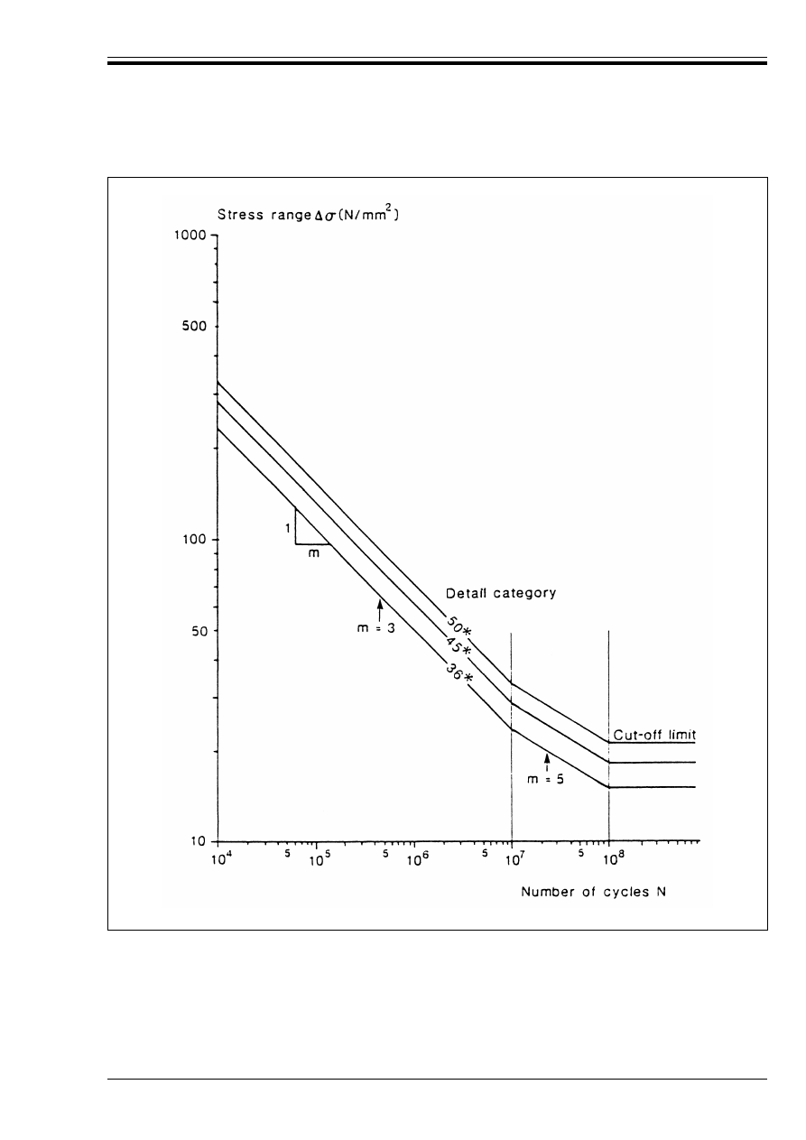
ENV 1993-1-1:1992
© BSI 04-2000
181
Figure 9.7.1 — Modified fatigue strength curve
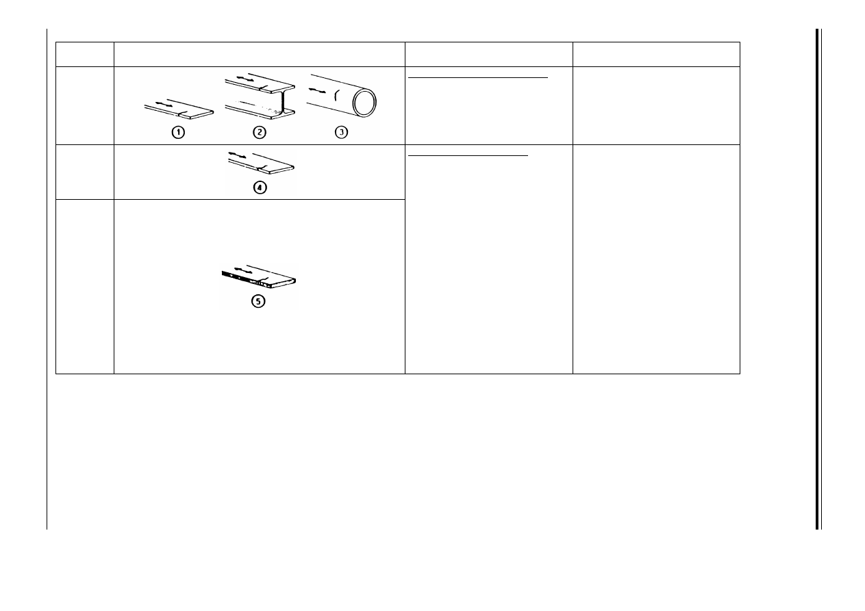
E
N
V
19
93
-1
-1
:1
99
2
18
2
©
B
S
I 0
4-
20
00
Table 9.8.1 — Non-welded details — sheet 1 of 2
Detail
category
Constructional details
Description
Requirement
160
Rolled and extruded products
e Plates and flats.
f Rolled sections.
g Seamless hollow sections
(see Table 9.8.6 and
Table 9.8.7.
e to g:
Sharp edges, surface and
rolling flaws to be improved by
grinding.
140
Sheared or gas cut plates
h Machine gas cut or sheared
material with no drag lines.
h All visible signs of edges
discontinuities should be
removed.
125
i Manually gas cut material or
material with machine gas cut
edges with shallow and
regular drag lines.
i Subsequent dressed to remove
all edge discontinuities.
h and i
— No repair by weld refill.
— Re-entrant corners
(slope < 1 : 4) or aperture
should be improved by
grinding for any visible
defects.
— At apertures the design stress
area should be taken as the net
cross section area.
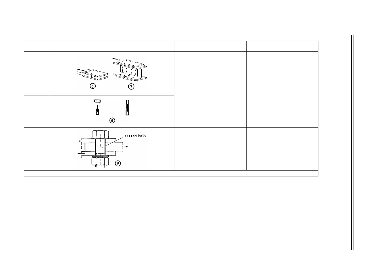
E
N
V
19
93
-1
-1
:1
99
2
©
B
S
I 0
4-
20
00
18
3
Table 9.8.1 — Non-welded details — sheet 2 of 2
Detail
category
Constructional details
Description
Requirement
112
Bolted connections
j Unsupported one-sided
connections shall be avoided
or else effects of eccentricities
taken into account when
calculating stresses.
k Beam splices or bolted cover
plates.
j and k
— Stresses to be calculated in the
gross section for slip resistant
connections or in the net section
for all other connections.
36
a
l Bolts and threaded rods in
tension. For preloaded bolts,
the stress range in the bolt
depends upon the level of
preload and the geometry of
the connection.
l
— Tensile stresses to be
calculated using the tensile
stress area of the bolt.
100
m = 5
Bolts in single or double shear
m Fitted bolt of bearing type
made of high strength steel as
defined in chapter 3
(bolts grade 8.8 and 10.9).
m
— Design shear stress evaluated
using the shank area of the
bolt.
— Only bearing type fitted bolts
are covered by this detail
category.
a
See clause 9.7.3
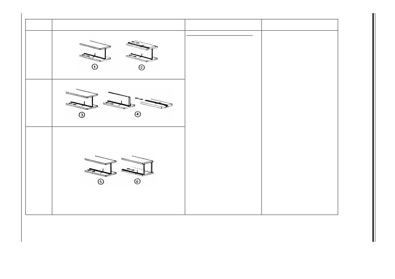
E
N
V
19
93
-1
-1
:1
99
2
18
4
©
B
S
I 0
4-
20
00
Table 9.8.2 — Welded built-up sections — sheet 1 of 2
Detail
category
Constructional details
Description
Requirement
125
Continuous longitudinal welds
e Automatic butt welds carried
out from both sides. If a
specialist inspection
demonstrates that
longitudinal welds are free
from significant flaws,
category 140 may be used.
f Automatic fillet welds. Cover
plate ends shall be verified
using detail
i in Table 9.8.5.
g Automatic fillet or butt welds
carried out from both sides but
containing stop/start
positions.
h Automatic butt welds made
from one side only, with a
backing bar, but without
stop/start positions.
i Manual fillet or butt welds.
j Manual or automatic butt
welds carried out from one
side only, particularly for box
girders.
e and f
— No stop/start position is
permitted except when the
repair is performed by a
specialist and inspection
carried out to verify the proper
execution of the repair.
h
— When this detail contains
stop/start positions use
category 100.
j
— A very good fit between the
flange and web plates is
essential. Prepare the web edge
such that the root face is
adequate for the achievement
of regular root penetration
without break-out.
112
100
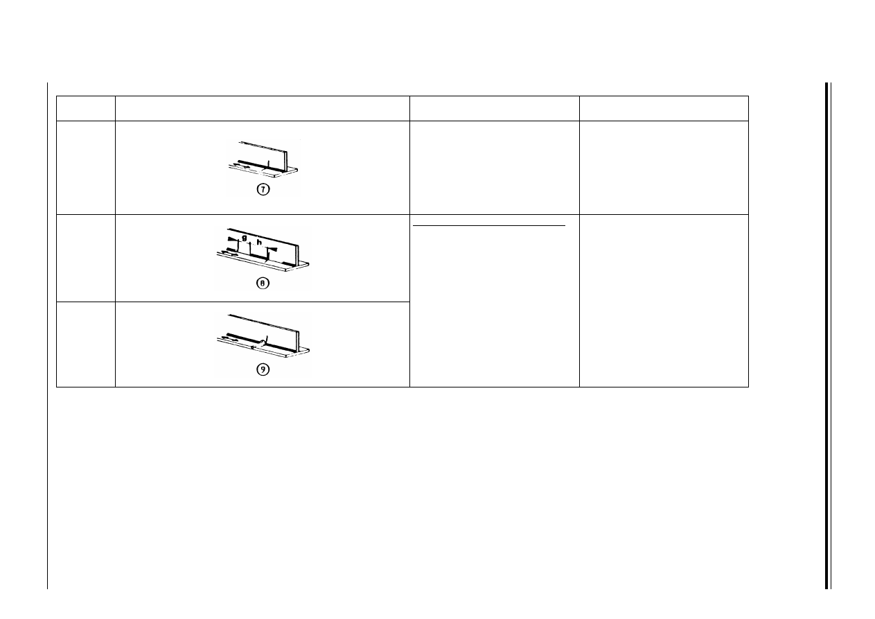
E
N
V
19
93
-1
-1
:1
99
2
©
B
S
I 0
4-
20
00
18
5
Table 9.8.2 — Welded built-up sections — sheet 2 of 2
Detail
category
Constructional details
Description
Requirement
100
k Repaired automatic or manual
fillet or butt welds.
k
— Improvement methods which
are adequately verified may
restore the original category.
80
Intermittent longitudinal welds
l Stitch or tack welds not
subsequently covered by a
continuous weld.
l
— Intermittent fillet weld with
gap ratio g/h u 2.5.
71
m Ends of continuous welds at
cope holes.
m
— Cope hole not to be filled with
weld metal.
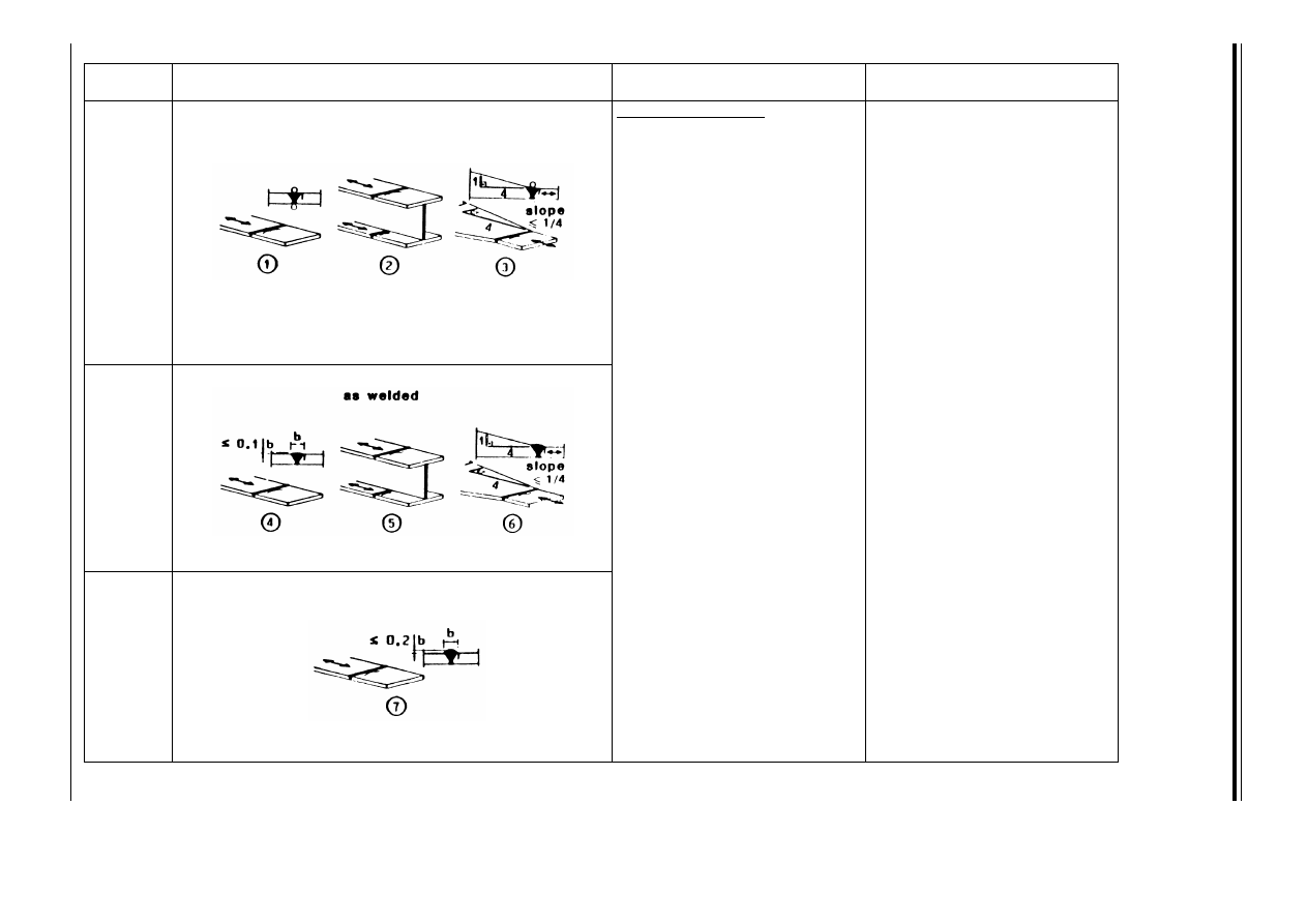
E
N
V
19
93
-1
-1
:1
99
2
18
6
©
B
S
I 0
4-
20
00
Table 9.8.3 — Transverse butt welds — sheet 1 of 2
Detail
category
Constructional details
Description
Requirement
112
Without backing bar
e Transverse splices in plates,
flats and rolled sections.
f Flange splices in plate girders
before assembly.
g Transverse splices in plates or
flats tapered in width or in
thickness where the slope is
not greater than 1 : 4.
e and f
— Details
e and f may be
increased to Category 125
when high quality welding is
achieved and is verified to
satisfy the tolerances of
Reference Standard 9 —
Quality level 3.
e, f and g
— All welds ground flush to plate
surface parallel to direction of
the arrow.
90
h Transverse splices in plates or
flats.
i Transverse splices in rolled
sections or welded plate
girders.
j Transverse splices in plates or
flats tapered in width or in
thickness where the slope is
not greater than 1 : 4.
h, i and j
— The height of the weld
convexity to be not greater
than 10 % of the weld width,
with smooth transitions to
plate surface.
— Welds made in flat position.
80
k Transverse splices in plates,
flats, rolled sections or plate
girders.
k
— The height of the weld
convexity to be not greater
than 20 % of the weld width.
e to k
— Weld run-off pieces to be used
and subsequently removed,
plate edges to be ground flush
in direction of stress.
— Welds made from two sides.
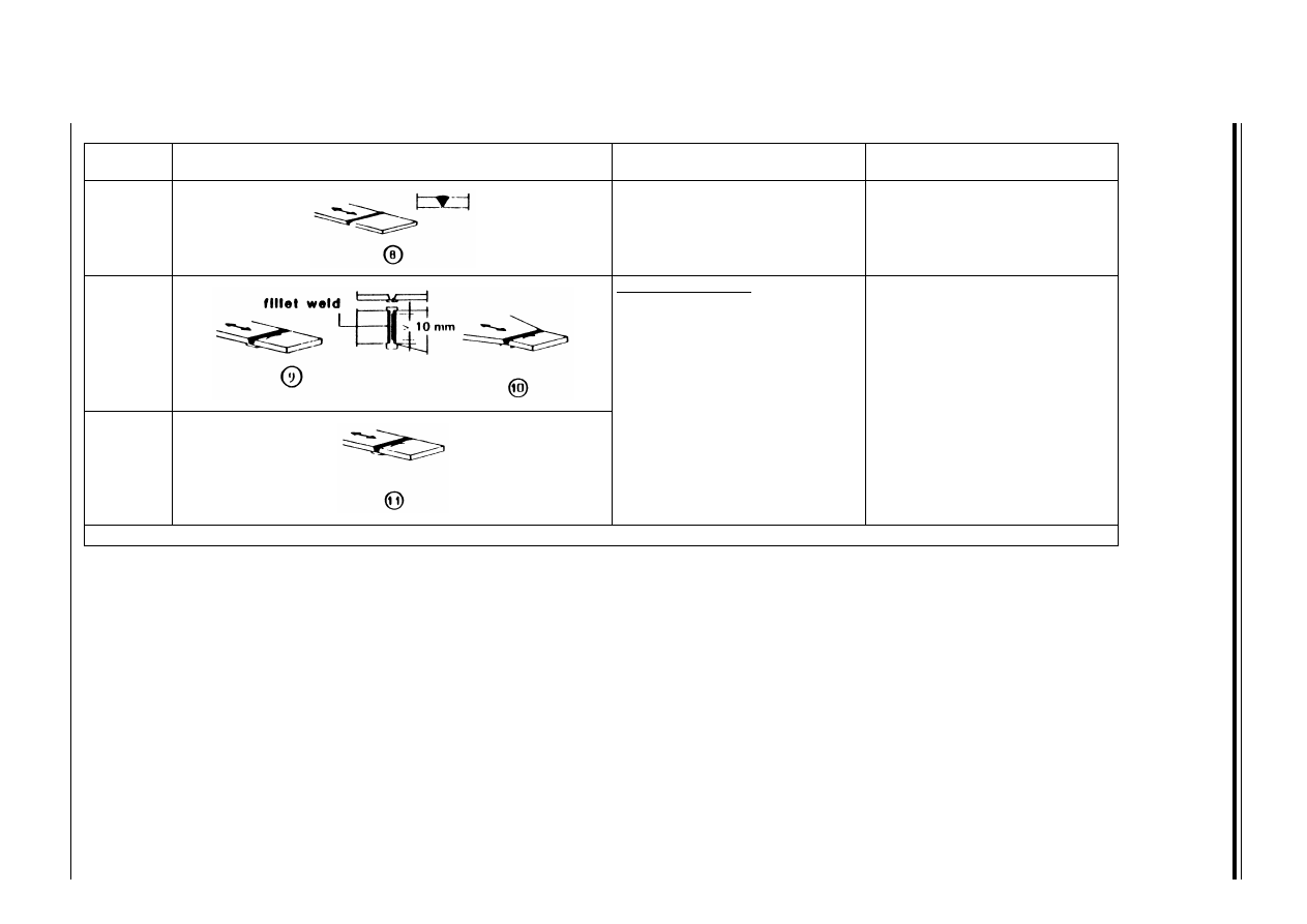
E
N
V
19
93
-1
-1
:1
99
2
©
B
S
I 0
4-
20
00
18
7
Table 9.8.3 — Transverse butt welds — sheet 2 of 2
Detail
category
Constructional details
Description
Requirement
36
a
l Butt welds made from one side
only.
l
— Without backing strip.
71
With backing strip
m Transverse splice.
n Transverse butt weld tapered
in width or in thickness where
the slope is not greater
than 1 : 4.
m and n
— The fillet weld which attaches
the backing strip to terminate
more then 10 mm from the
edges of the stressed plate.
50
o Transverse butt weld on a
permanent backing strip.
o
— When backing strip fillet welds
are terminated closer
than 10 mm to the plate edge,
or when good fit cannot be
guaranteed.
a
See clause 9.7.3
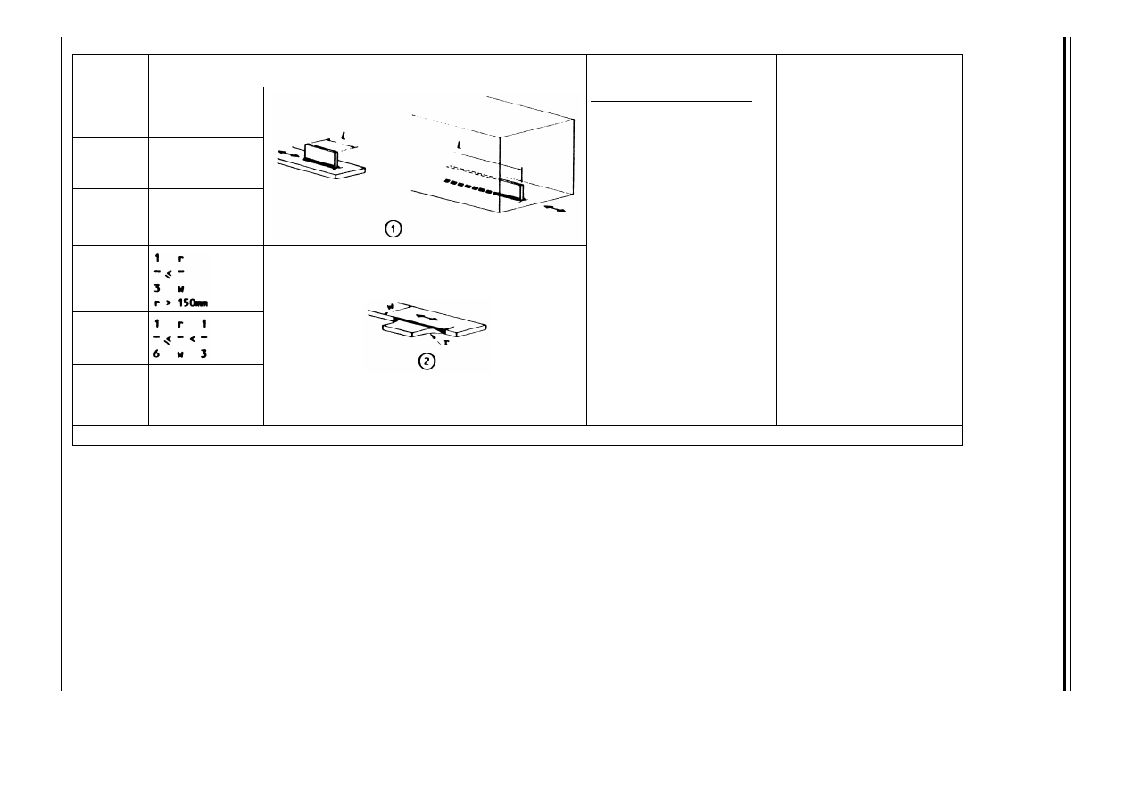
E
N
V
19
93
-1
-1
:1
99
2
18
8
©
B
S
I 0
4-
20
00
Table 9.8.4 — Welded attachements with non-load carrying welds — sheet 1 of 2
Detail
category
Constructional details
Description
Requirement
80
L u 50 mm
Longitudinal attachments
e The Detail Category
varies according to the
length of the attachment,
L.
71
50 < L u 100 mm
50
a
L > 100 mm
90
f Gusset plate, welded to
the edge of plate or beem
flange.
f
— Smooth transition radius,
r, formed by initially
machining or gas cutting
the gusset plate before
welding and then
subsequently grinding
the weld area parallel to
the direction of the arrow.
71
45
a
<
a
See clause 9.7.3
r
w
----
1
6
---
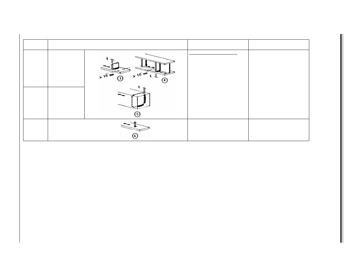
E
N
V
19
93
-1
-1
:1
99
2
©
B
S
I 0
4-
20
00
18
9
Table 9.8.4 — Welded attachments with non-load carrying welds — sheet 2 of 2
Detail
category
Constructional details
Description
Requirement
80
t u 12 mm
Transverse attachments
g Welds which terminate
more than 10 mm from
the edge of the plate.
h Vertical stiffeners welded
to a beam or a plate girder.
h
— The stress range should be
calculated using principal
stresses if the stiffener
terminates in the web.
71
t > 12 mm
i Diaphragms of box girders
welded to the flange or
web.
80
j The effect of welded shear
connectors on base
material.
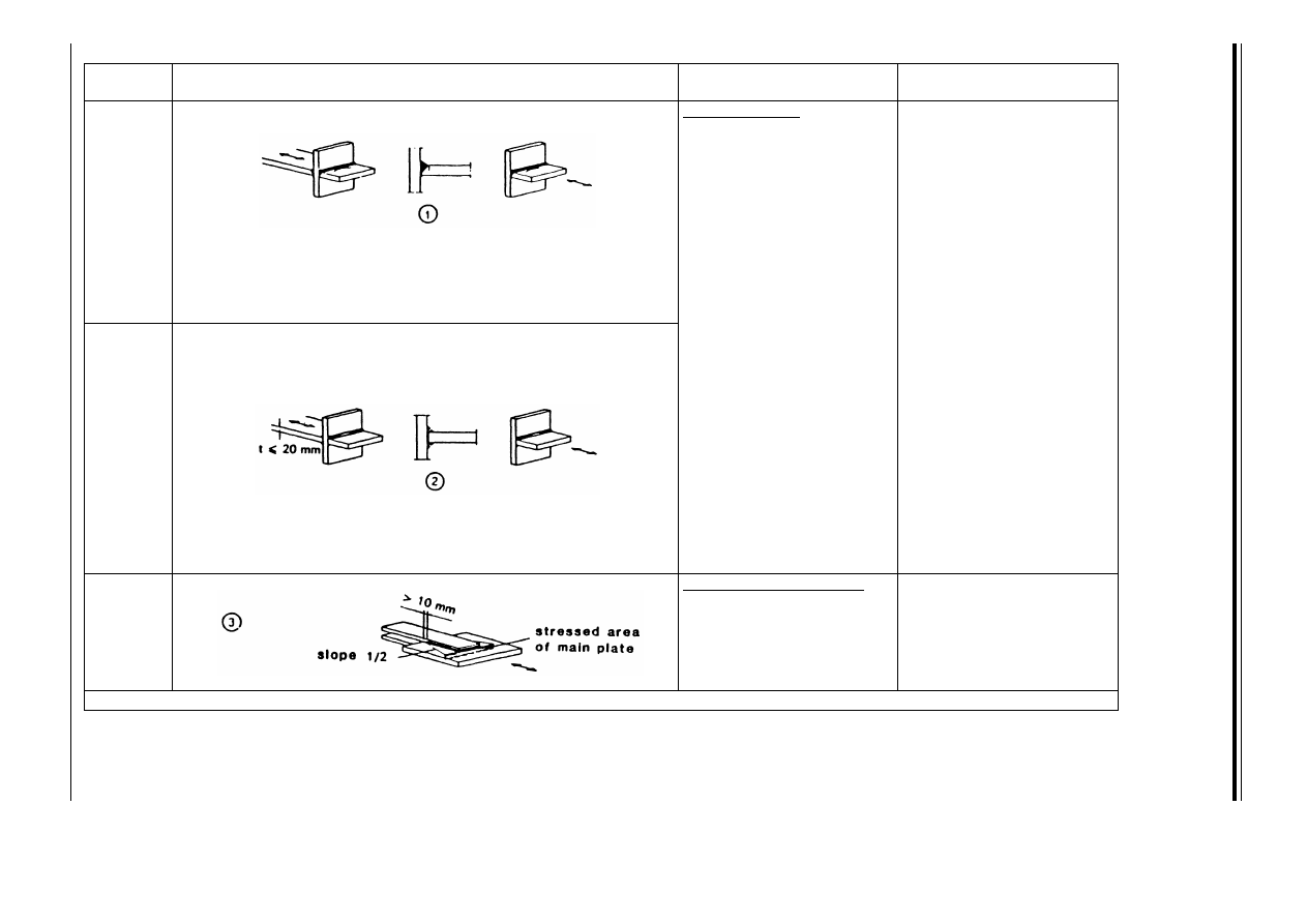
E
N
V
19
93
-1
-1
:1
99
2
19
0
©
B
S
I 0
4-
20
00
Table 9.8.5 — Welded joints with load-carrying welds — sheet 1 of 3
Detail
category
Constructional details
Description
Requirement
71
Cruciform joints
e Full penetration butt
weld.
e
— Inspected and found free
from discontinuities
outside the tolerances of
Reference Standard 9 —
Quality Level 3.
f
— Two fatigue assessments
are required. Firstly, root
cracking is evaluated
according to 9.4.3, taking
Category 36
a
for B
w
and
Category 80 for Ù
w
. Secondly,
toe cracking is evaluated by
determining the stress range
in the load-carrying plates,
Category 71.
e and f
— The misalignment of the
load-carrying plates
should not exceed 15 % of
the thickness of the
intermediate plate.
36
a
f Partial penetration
tee-butt joint or fillet
welded joint and effective
full penetration in
tee-butt joint as defined
in Figure 6.6.9(a).
63
Overlapped welded joints
g Fillet welded lap joint.
g
— Stress in the main plate to
be calculated on the basis
of area shown in the
sketch.
a
See clause 9.7.3
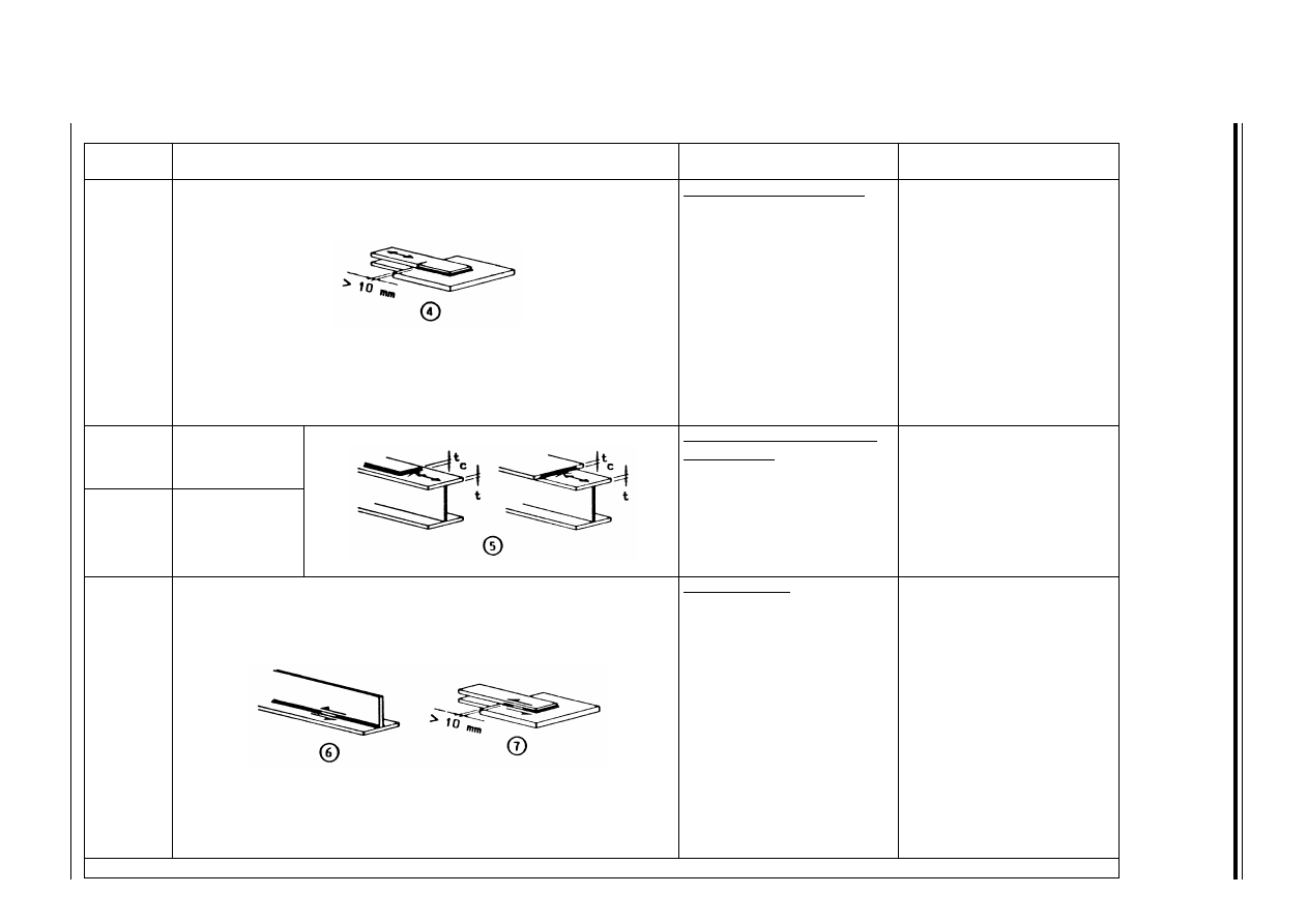
E
N
V
19
93
-1
-1
:1
99
2
©
B
S
I 0
4-
20
00
19
1
Table 9.8.5 — Welded joints with load-carrying welds — sheet 2 of 3
Detail
category
Constructional details
Description
Requirement
45
a
Overlapped welded joints
h Fillet welded lap joint.
h
— Stress to be calculated in
the overlapping plate
elements.
g and h
— Weld terminations more
then 10 mm from plate
edge.
— Shear cracking in the weld
should be verified using
detail
k.
50
a
t and t
c
u 20 mm
Cover plates in beams and
plate girders
i End zones of single or
multiple welded cover
plates, with or without
frontal weld.
i
— When the cover plate is
wider than the flange, a
frontal weld, carefully
ground to remove
undercut, is necessary.
36
a
t or t
c
> 20 mm
80
m = 5
Welds in shear
j Continuous fillet welds
transmitting a shear
flow, such as web to
flange welds in plate
girders. For continuous
full penetration butt weld
in shear use category 100.
k Fillet welded lap joint.
j
— Stress range to be
calculated from the weld
throat area.
k
— Stress range to be
calculated from the weld
throat area considering
the total length of the
weld.
— Weld terminations more
than 10 mm from plate
edge.
a
See clause 9.7.3
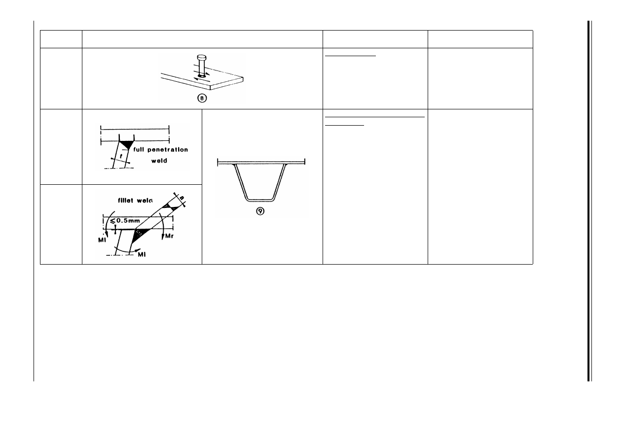
E
N
V
19
93
-1
-1
:1
99
2
19
2
©
B
S
I 0
4-
20
00
Table 9.8.5 — Welded joints with load-carrying welds — sheet 3 of 3
Detail
category
Constructional details
Description
Requirement
80
m = 5
Welds in shear
l Stud connectors
(failure in the weld or heat
effected zone).
l
— The shear stress to be
calculated on the nominal
cross-section of the stud.
71
Trapezoidal stiffener to deck
plate welds
m With fillet weld or full or
partial penetration butt
weld.
m
— For a full penetration butt
weld, the bending stress
range shall be calculated
on the basis of the
thickness of the stiffener.
— For fillet weld or a partial
penetration butt weld, the
bending stress range shall
be calculated on the basis
of the throat thickness of
the weld, or the thickness
of the stiffener if smaller.
50
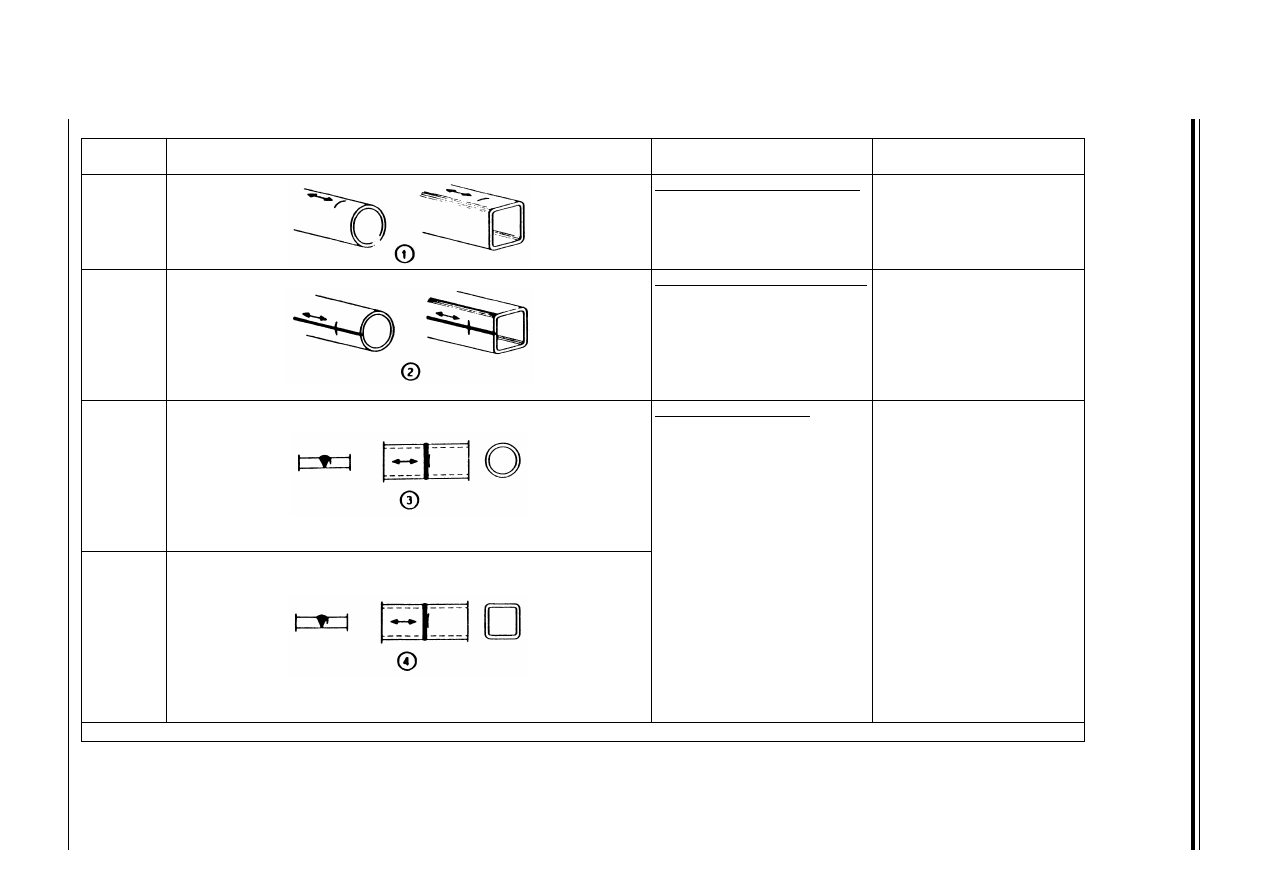
E
N
V
19
93
-1
-1
:1
99
2
©
B
S
I 0
4-
20
00
19
3
Table 9.8.6 — Hollow sections — sheet 1 of 2(
a
)
Detail
category
Constructional details
Description
Requirement
160
Rolled and extruded products
e Non-welded elements.
e
— Sharp edges and surface
flaws to be improved by
grinding.
140
Continuous longitudinal welds
f Automatic longitudinal
seam welds (for all other
cases, see Table 9.8.2).
f
— No stop/start positions,
end free from defects
outside the tolerances of
Reference Standard 9 —
Quality Level 3.
71
Transverse butt welds
g Butt-welded end-to-end
connection of circular
hollow sections.
g and h
— Height of the weld
convexity less then 10 %
of the weld width, with
smooth transitions to the
plate surface.
— Welds made in flat position
and inspected and found
free from defects outside
the tolerances of
Reference Standard 9 —
Quality Level 3.
— Details with wall
thicknesses greater
then 8 mm may be
classified two Category
higher.
56
h Butt-welded end-to-end
connection of rectangular
hollow sections.
a
(t u 12.5 mm)
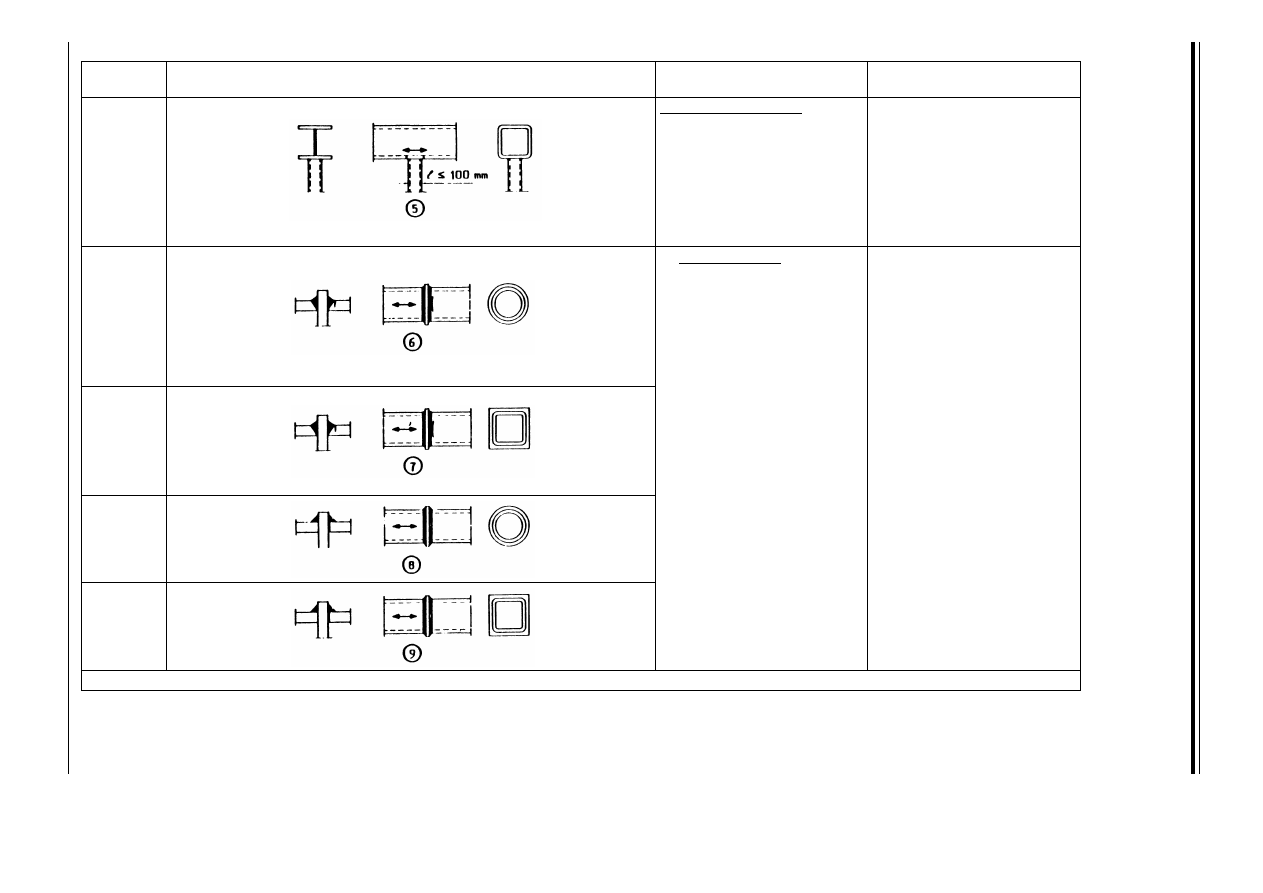
E
N
V
19
93
-1
-1
:1
99
2
19
4
©
B
S
I 0
4-
20
00
Table 9.8.6 — Hollow sections — sheet 2 of 2(
a
)
Detail
category
Constructional details
Description
Requirement
71
Welded attachments
i Circular or rectangular
hollow section, fillet
welded to another section.
i
— Non-load-carrying welds.
— Section width parallel to
stress
direction u 100 mm.
— All other cases,
see Table 9.8.4.
50
— Welded splices
j Circular hollow sections,
butt welded
end-to-end with an
intermediate plate.
j and k
— Load-carrying welds.
— Welds inspected and found
free from defects outside
the tolerances of
Reference Standard 9 —
Quality Level 3.
— Details with wall
thickness greater
than 8 mm may be
classified one Detail
Category higher.
l and m
— Load-carrying welds.
— Wall thickness less
than 8 mm.
45
k Rectangular
hollow sections, butt
welded end-to-end with an
intermediate plate.
40
l Circular hollow sections,
fillet welded end-to-end
with an intermediate
plate.
36
m Rectangular hollow
sections, fillet welded
end-to-end with an
intermediate plate.
a
(t u 12.5 mm)
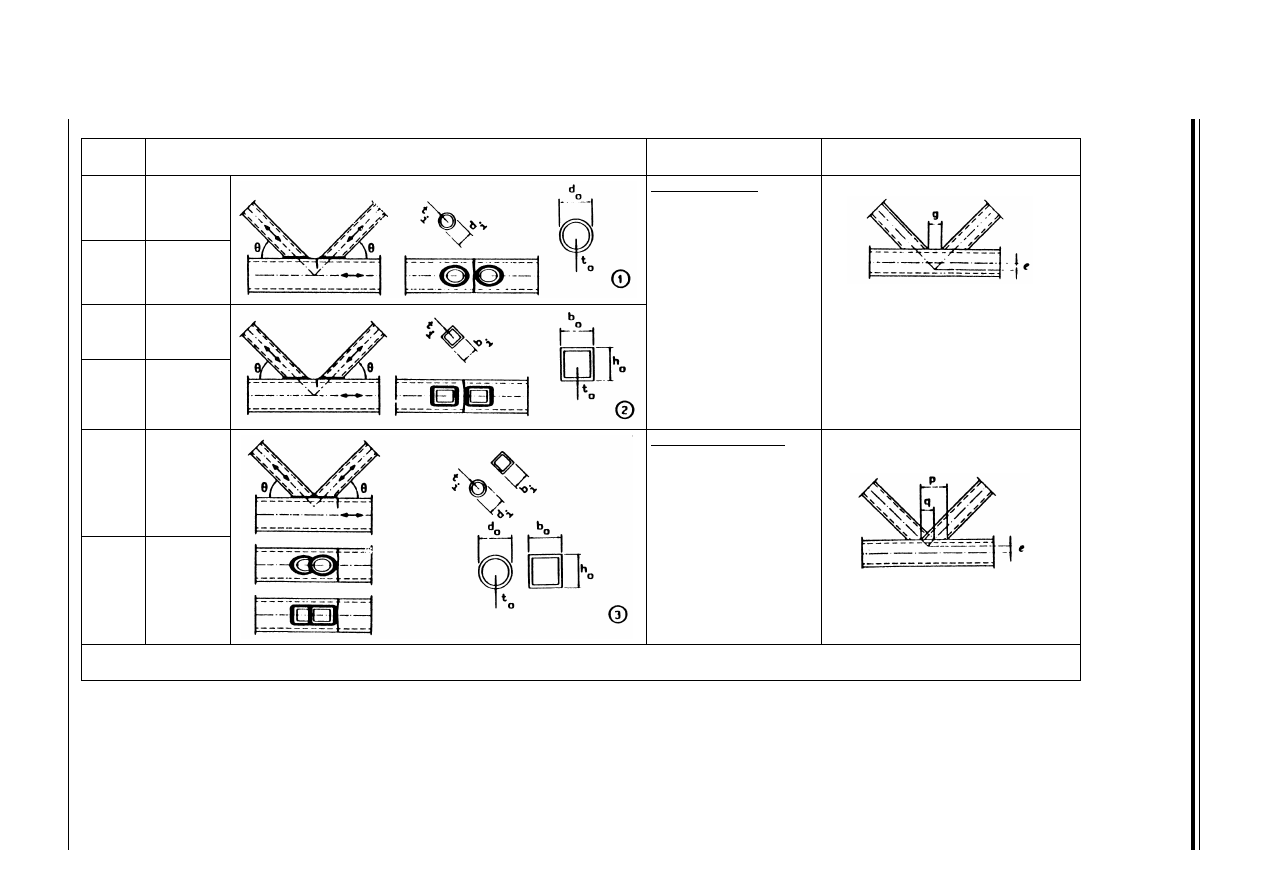
E
N
V
19
93
-1
-1
:1
99
2
©
B
S
I 0
4-
20
00
19
5
Table 9.8.7 — Lattice girder joints — sheet 1 of 2 (m = 5)
Detail
category
Constructional details
Description
Requirement
90
W 2.0
Joints with gap (*)
e Circular hollow
sections, K and N joints.
45
71
W 2.0
f Rectangular hollow
sections, K and N
joints.
f
— 0.5 (b
o
– b
i
) u g u 1.1 (b
o
– b
i
)
— g W 2 t
o
g: gap
e: positive eccentricity
36
71
W 1.4
Joints with overlap (*)
g K-joint.
g and h
— Overlap between 30 % and 100 %.
: overlap
e: negative eccentricity
56
— Note that the braces and the chords require separate fatigue assessments.
— (*) For intermediate t
o
/t
i
values, use linear interpolation between nearest Detail Categories.
t
o
t
i
----
t
o
t
i
----
1.0
=
t
o
t
i
----
t
o
t
i
----
1.0
=
t
o
t
i
----
q
p
--- 100
⋅
t
o
t
i
----
1.0
=
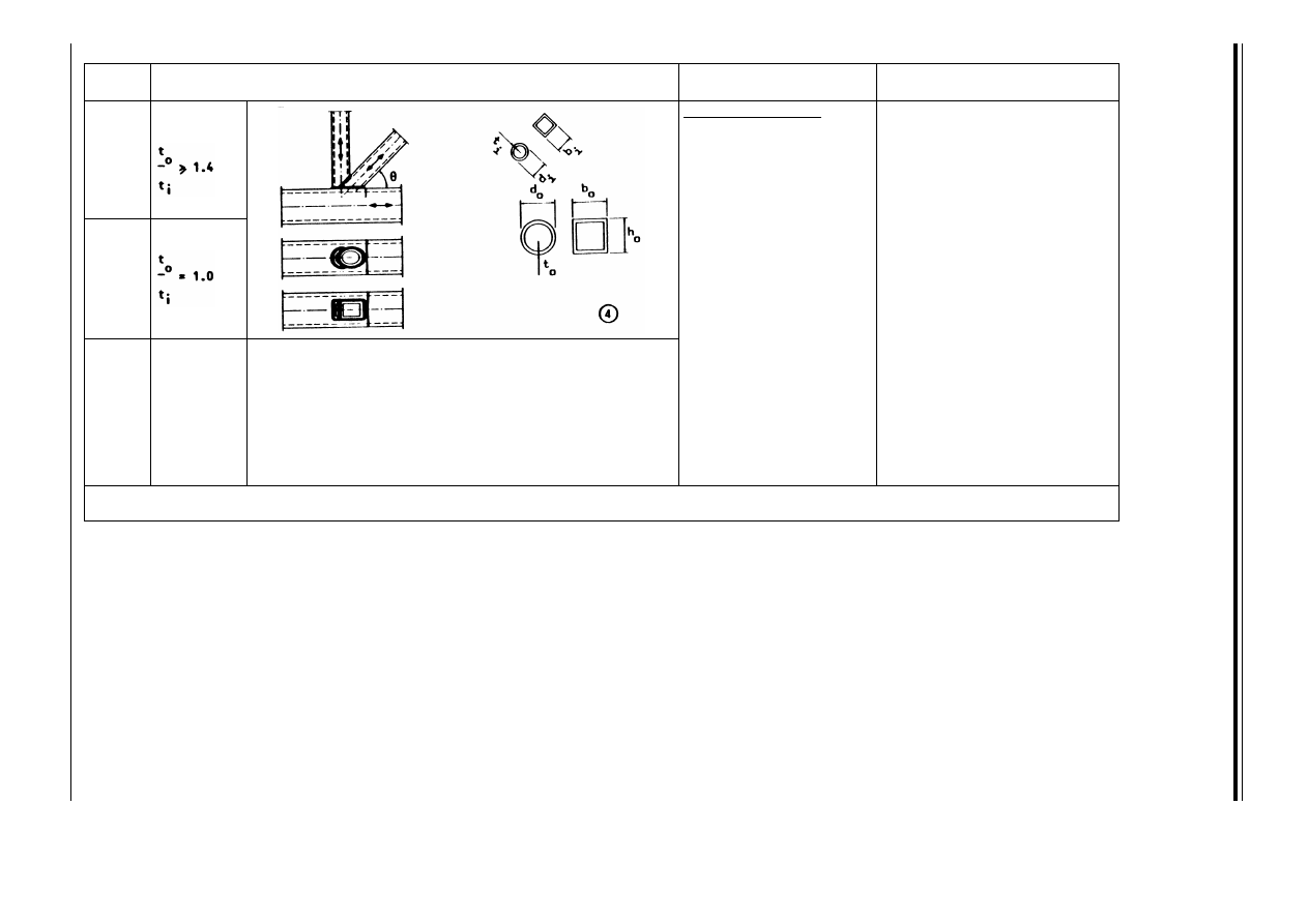
E
N
V
19
93
-1
-1
:1
99
2
19
6
©
B
S
I 0
4-
20
00
Table 9.8.7 — Lattice girder joints — sheet 2 of 2 (m = 5)
Detail
category
Constructional details
Description
Requirement
71
Joints with overlap (*)
h N-joints.
e to h
— t
o
, t
i
u 12.5 mm
— 35
o
u F u 50
o
— b
o
/t
o
u 25
— d
o
/t
o
u 25
— 0.4 u b
i
/b
o
u 1.0
— 0.25 u d
i
/d
o
u 1.0
— b
o
u 200 mm
— d
o
u 300 mm
— – 0.5 h
o
u e u 0.25 h
o
— 0.5 d
o
u e u 0.25 d
o
— Out of plane eccentricity:
u 0.02 b
o
or u 0.02 d
o
— Fillet welds are permitted in
braces with wall
thicknesses u 8 mm
— For wall thicknesses greater
than 12.5 mm
see clause 9.6.3.
50
— Note that the braces and the chords require separate fatigue assessments.
— (*) For intermediate t
o
/t
i
values, use linear interpolation between nearest Detail Categories.

ENV 1993-1-1:1992
© BSI 04-2000
197
Annex B (normative)
Reference standards
B.1 Scope
(1) This Part 1.1 of Eurocode 3 mentions 10 Reference Standards. They define the product standards and
execution standards which apply to steel structures designed in accordance with Eurocode 3-1.1.
B.2 Definitions
B.2.1 Reference Standard 1: “Weldable structural steel”
(1) European Standard EN 10025 “Hot rolled products of non-alloy structural steels — Technical delivery
conditions” grades Fe 360, Fe 430 and Fe 510 only.
(2) European Standard prEN 10113 “Hot rolled products in weldable fine grain structural steels” grades Fe
E 275 and Fe E 355 only.
(3) For prEN 10113 grades Fe E 420 and Fe E 460 refer to Annex D
24)
.
(4) European Standard prEN 10210-1 “Hot finished steel hollow sections: Part 1 Technical delivery
requirements”
24)
.
(5) European Standard prEN 10219-1 “Cold formed structural steel hollow sections: Part 1 Non-alloy and
fine grain steels”
24)
.
(6) It shall be ensured that the weldability of the material is sufficient for the purpose for which it is
required.
(7) For cold formed thin gauge members and sheeting refer to prENV 1993-1-3 Eurocode 3-1.3
24)
.
B.2.2 Reference Standard 2: “Dimensions of sections and plates”
B.2.2.1 Hot rolled sections, other than structural hollow sections
(1) The Euronorms for sections listed in European Standard EN 10025 modified as follows:
• excluding tolerances
• including the “corresponding national standards” for hot rolled sections listed in Annex B of
EN 10025 (but excluding tolerances).
(2) European Standard EN...... “Hot rolled tapered flange and parallel flange channels — dimensions and
tolerances” (when available).
(3) European Standard EN...... “Hot rolled tees — Dimensions and tolerances” (when available)
(4) European Standard EN...... “Hot rolled bulb flats — Dimensions and tolerances” (when available).
(5) European Standard EN...... “Hot rolled I and H sections — Dimensions” (when available).
(6) European Standard EN...... “Hot rolled split tees — Dimensions and tolerances” (when available).
(7) European Standard EN...... “Hot rolled equal leg and unequal leg angles — Dimensions” (when
available).
(8) International Standard ISO 657 “Hot rolled steel sections”: Part 1 “Equal leg angles” and Part 2
“Unequal leg angles”.
(9) European Standard EN...... “Hot rolled flat, square and round steel bars — Dimensions” (when
available).
(10) European Standard EN...... “Hot rolled square steel bars — Dimensions” (when available).
(11) European Standard EN...... “Hot rolled round steel bars — Dimensions” (when available).
B.2.2.2 Hot rolled structural hollow sections
(1) European Standard prEN 10210-2 “Hot finished steel hollow sections: Part 2 Dimensions and
tolerances”
24)
.
(2) International Standard ISO 657 “Hot rolled steel sections”: Part 14 “Hot finished structural hollow
sections, dimensional and sectional properties”, as follows:
• except that steel is to be to EN 10025
24)
In preparation

ENV 1993-1-1:1992
198
© BSI 04-2000
B.2.2.3 Cold finished structural hollow sections
(1) European Standard prEN 10219-2 “Cold formed structural steel hollow sections: Part 2 Dimensions and
tolerances”
25)
.
(2) International Standard ISO 4019 “Cold finished steel structural hollow sections — Dimensions and
sectional properties”.
B.2.2.4 Cold formed sections, other than structural hollow sections
(1) For cold formed thin gauge members and sheeting refer to prENV 1993-1-3 Eurocode 3-1.3
25)
.
B.2.3 Tolerances
B.2.3.1 Hot rolled sections, other than structural hollow sections
(1) European Standard prEN 10034 “Structural steel I and H sections — Tolerances on shape and
dimensions”
25)
.
(2) European Standard prEN 10056 “Structural steel equal leg and unequal leg angles — Tolerances on
shape and dimensions”
25)
.
(3) European Standard EN ...... “Hot rolled tapered flange and parallel flange channels — Dimensions and
tolerances” (when available).
(4) European Standard EN ...... “Hot rolled tees — Dimensions and tolerances” (when available).
(5) European Standard EN ...... “Hot rolled bulb flats — Dimensions and tolerances” (when available).
(6) European Standard EN ...... “Hot rolled split tees — Dimensions and tolerances” (when available).
(7) European Standard EN ...... “Hot rolled square steel bars — Tolerances” (when available).
(8) European Standard EN ...... “Hot rolled round steel bars — Tolerances” (when available).
B.2.3.2 Structural hollow sections
(1) European Standard prEN 10210-2 “Hot finished steel hollow sections — Part 2 Dimensions and
tolerances”
25)
.
(2) European Standard prEN 10219-2 “Cold formed structural steel hollow sections — Part 2 Dimensions
and tolerances”
25)
.
B.2.3.3 Cold formed sections, other than structural hollow sections
(1) For cold formed thin gauge members and sheeting refer to prENV 1993-1-3 Eurocode 3-1.3
25)
.
B.2.3.4 Plates and flats
(1) European Standard EN 10029 “Tolerances on dimensions, shape and mass for hot rolled steel
plates 3 mm thick or above” as follows:
• Class A tolerances
(2) European Standard EN..... “Tolerance requirements for wide flats” (when available).
(3) European Standard EN..... “Tolerance requirements for flat bars” (when available).
B.2.4 Reference Standard 3: “Bolts, nuts and washers”
B.2.4.1 Non-preloaded bolts
(1) Bolts to European Standards EN 24014, EN 24016, EN 24017 or EN 24018, nuts to EN 24032,
EN 24034 or ISO 7413, washers to ISO 7089, ISO 7090 or ISO 7091.
(2) Bolts to International Standard ISO 7411, nuts to ISO 4775, washers to ISO 7415 or ISO 7416.
(3) Bolts to International Standard ISO 7412, nuts to ISO 7414, washers to ISO 7415 or ISO 7416.
B.2.4.2 Preloaded bolts
(1) Bolts to International Standard ISO 7411, nuts to ISO 4775, washers to ISO 7415 or ISO 7416.
B.2.5 Reference Standard 4: “Welding Consumables”
(1) European Standard EN ..... “Welding consumables” (when available).
B.2.6 Reference Standard 5: “Rivets”
(1) European Standard EN ..... “Structural steel rivets” (when available).
25)
In preparation

ENV 1993-1-1:1992
© BSI 04-2000
199
B.2.7 Reference Standards 6 to 9: “Execution standards”
(1) European Standard EN ..... “Execution of steel structures” Part 1 “General rules and rules for
buildings”
26)
.
B.2.8 Reference Standard 10: “Corrosion protection”
(1) European Standard EN ..... “Corrosion protection” (when available).
Annex C (informative)
Design against brittle fracture
C.1 Resistance to brittle fracture
(1) Brittle fracture is characterized as failure of a structural element without plastic deformation.
The failure mode is mainly dependent on the following:
• steel strength grade
• thickness of the material
• loading speed
• lowest service temperature
• material toughness
• type of structural element
(2) The required steel grade can be determined by considering the factors listed above. The choice depends
on the toughness of the material and the requirements in terms of fracture mechanics. The criterion is
expressed in terms of the test temperature at which the Charpy V-notch energy has a minimum value
of 27 Joules.
(3) The procedure which follows determines the lowest service temperature for a given grade and thickness
of steel, depending on the service conditions, the loading rate and the consequences of failure.
(4) The steel grades in this procedure refer to material conforming with EN 10025 or prEN 10113.
(5) The procedure given in this Annex should not be applied for service temperatures below – 40 °C.
C.2 Calculation procedure
C.2.1 Service Conditions
(1) Three levels of severity are defined, with stress levels calculated using the characteristic values of the
actions and a partial safety factor ¾
F
= 1,0 as follows:
• S1: Either:
• no welding, or
• as-welded, with local tensile stresses not exceeding 0,2 times the yield strength, or
• full stress-relief post-weld heat treatment, with local tensile stresses (including any geometric
stress concentration) not exceeding 0,67 times the yield strength.
• S2: As-welded condition, with either:
• local tensile stresses in the range 0,2 to 0,67 times the yield strength, or
• post-weld heat treated stress concentrations with local stresses up to twice the yield strength.
• S3: Complex geometry stress concentration regions, either:
• as-welded with local tensile stresses in the range 0,67 to 2 times the yield strength, or
• post-weld heat treated with local stresses in the range of 2 to 3 times the yield strength,
but in all cases below plastic collapse.
(2) Table 3.2 is based on stress levels S1 and S2.
C.2.2 Loading rate
(1) Two loading rates are defined as follows:
• R1: Normal static or slow loading, applicable to structures subjected to self weight, floor loading,
vehicular loading, wind and wave loading and lifting loads.
26)
In preparation
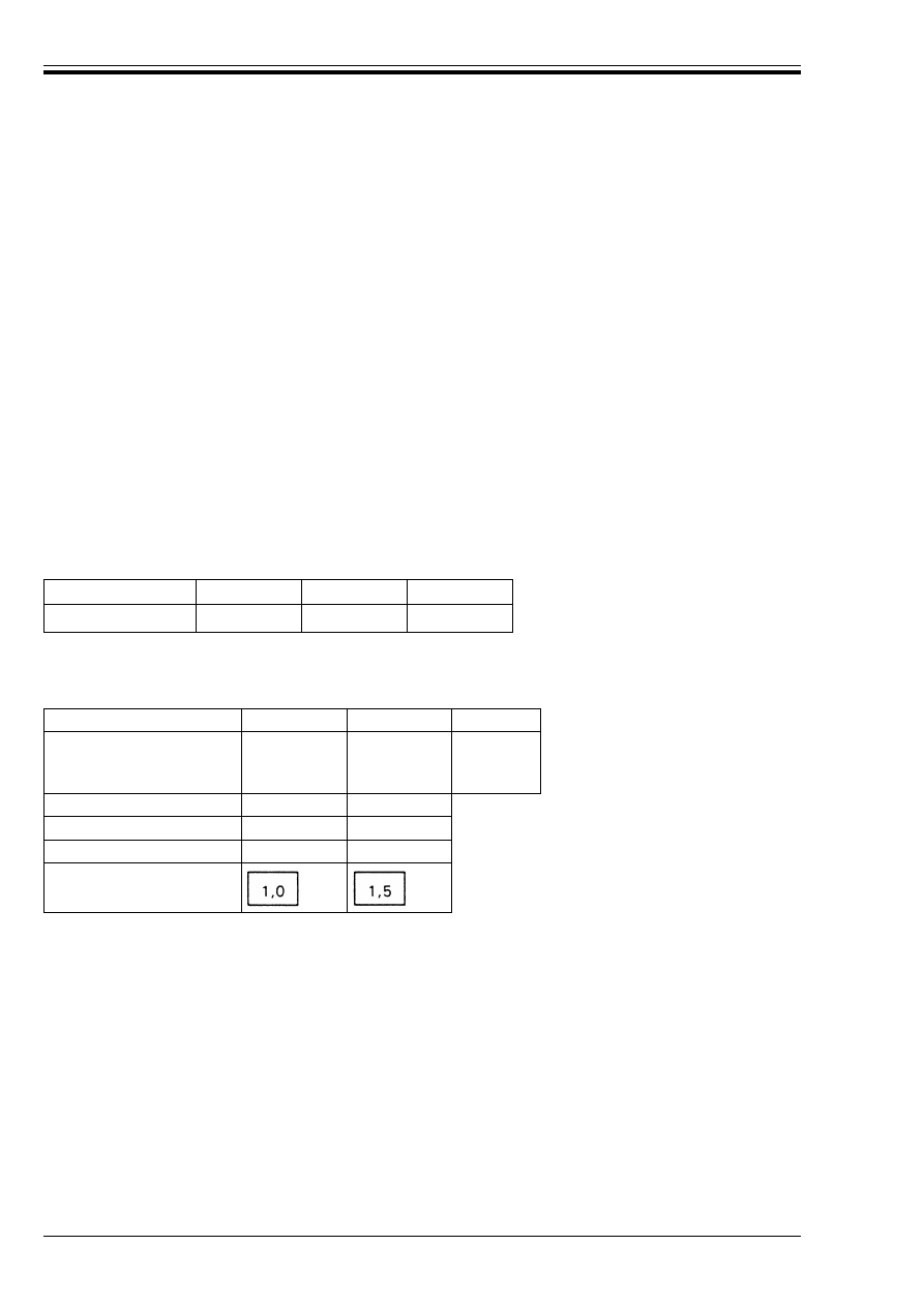
ENV 1993-1-1:1992
200
© BSI 04-2000
• R2: Impact loading, applicable to high strain rate, explosive or crash conditions.
(2) Table 3.2 is based on loading rate R1.
C.2.3 Consequences of failure
(1) Two conditions are defined as follows:
• C1: Non-critical members or joints, where failure would be restricted to local effects without serious
consequences (eg. redundant members).
• C2: Fracture critical members or joints, where local failure would cause complete structural collapse
with serious consequences to life or very high cost.
(2) Table 3.2 is based on condition C2.
C.2.4 Nominal yield strength
(1) The nominal value of the lower yield strength f
y
Ù
, reduces with thickness and may be obtained from:
(2) The base value of the mean lower yield strength f
yo
(for use in Annex C only) may be determined
from Table C.1.
Table C.1 — Base value of the mean lower yield strength
C.2.5 Parameters
(1) The values of the constants to be adopted for categories S, R and C shall be obtained from Table C.2.
Table C.2 — Values of constants
(2) Details of the Charpy V-notch test temperature T
cv
for standard notch-toughness grades of steel to
EN 10025 are given in Table C.3.
(3) Relevant details of the Charpy V-notch test temperature T
cv
for steel to prEN 10113 are also given in
Table C.3.
f
y
Ù
= f
yo
– 0,25 (t/t
1
) (f
yo
/235)
(C.1)
where f
yo
is the base value of f
y
Ù
(in N/mm
2
)
t
is the thickness (in mm)
and
t
1
= 1 mm
Grade of steel
Fe 360
Fe 430
Fe 510
f
yo
(N/mm
2
)
235
275
355
Stress category
S1
S2
S3
k
a
k
b
k
c
0,18
0,40
0,03
0,18
0,15
0,03
0,10
0,07
0,04
Loading rate
R1
R2
Value of k
d
10
–3
1,0
Consequences of failure
C1
C2
Value of ¾
c

ENV 1993-1-1:1992
© BSI 04-2000
201
Table C.3 — Charpy V-notch test temperature T
cv
C.2.6 Calculations
(1) The required fracture toughness K
1C
shall be obtained from:
in which:
µ = 1/[k
a
+ k
b
=n(t/t
1
) + k
c
(t/t
1
)
0,5
]
(2) The minimum service temperature T
min
shall be obtained from:
in which:
¶ = 100 (
=n K
1C
– 8,06)
Annex E (informative)
Buckling length of a compression member
E.1 Basis
(1) The buckling length = of a compression member is the length of an otherwise similar member with
“pinned ends” (ends restrained against lateral movement but free to rotate in the plane of buckling) which
has the same buckling resistance.
(2) In the absence of better information, the theoretical buckling length for elastic critical buckling may
conservatively be adopted.
(3) An equivalent buckling length may be used to relate the buckling resistance of a member subject to non-
uniform loading to that of an otherwise similar member subject to uniform loading.
(4) An equivalent buckling length may also be used to relate the buckling resistance of a non-uniform
member to that of a uniform member under similar conditions of loading and restraint.
E.2 Columns in building frames
(1) The buckling length = of a column in a non-sway mode may be obtained from Figure E.2.1.
(2) The buckling length = of a column in a sway mode may be obtained from Figure E.2.2.
(3) For the theoretical models shown in Figure E.2.3 the distribution factors ½
1
and ½
2
are obtained from:
Notch toughness
quality
Specified values
Nominal value of T
cv
(°C)
that may be
assumed to give 27 Joules for
thickness t
(mm)
Test temperature
(°C)
Minimum energy (J) for thickness
t
(mm)
> 10
k 150
1)
> 150
k 250
1)
> 150
1)
k150
k 250
1)
EN 10025
B
C
D
DD
prEN 10113
KG
KT
+ 20
0
– 20
– 20
– 20
– 50
27
27
27
40
40
27
23
23
23
33
33
23
+ 20
+ 0
– 20
– 30
2)
– 30
2)
– 50
+ 25
+ 5
– 15
– 25
2)
– 25
2)
– 45
Notes:
1. The value shall be agreed with the steel producer for rolled sections to EN 10025 with a nominal thickness over 100 mm, for steels
of delivery condition N to prEN 10113-2 with a nominal thickness over 150 mm and for steels of delivery condition TM to
prEN 10113-3 with a nominal thickness over 150 mm for long products or over 63 mm for flat products.
2. These values are assumed to be equivalent to a Charpy V-notch energy of 40 J at – 20 °C, or 33 J at – 20 °C for steel over 150 mm
up to 250 mm thick.
K
1C
= [¾
c
µ]
0,55
f
y
=
t
0,5
/1,226
(C.2)
T
min
= 1,4 T
cv
+ 25 + ¶ + (83 – 0,08 f
y
=
) [k
d
]
0,17
(C.3)
½
1
= K
c
/(K
c
+ K
11
+ K
12
)
(E.1)
½
2
= K
c
/(K
c
+ K
21
+ K
22
)
(E.2)
where K
c
is the column stiffness coefficient l/L
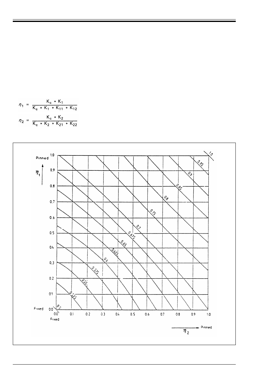
ENV 1993-1-1:1992
202
© BSI 04-2000
(4) These models may be adapted to the design of continuous column, by assuming that each length of
column is loaded to the same value of the ratio (N/N
cr
). In the general case where (N/N
cr
) varies, this leads
to a conservative value of =/L for the most critical length of column.
(5) For each length of a continuous column the assumption made in (4) may be introduced by using the
model shown in Figure E.2.4 and obtaining the distribution factors ½
1
and ½
2
from:
where K
1
and K
2
are the stiffness coefficients for the adjacent lengths of column.
and
K
ij
is the effective beam stiffness coefficient
(E.3)
(E.4)
Figure E.2.1 — Buckling length ratio =/L for a column in a non-sway mode
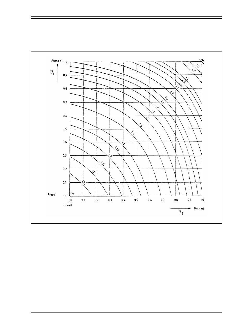
ENV 1993-1-1:1992
© BSI 04-2000
203
Figure E.2.2 — Buckling length ratio =/L for a column in a sway mode
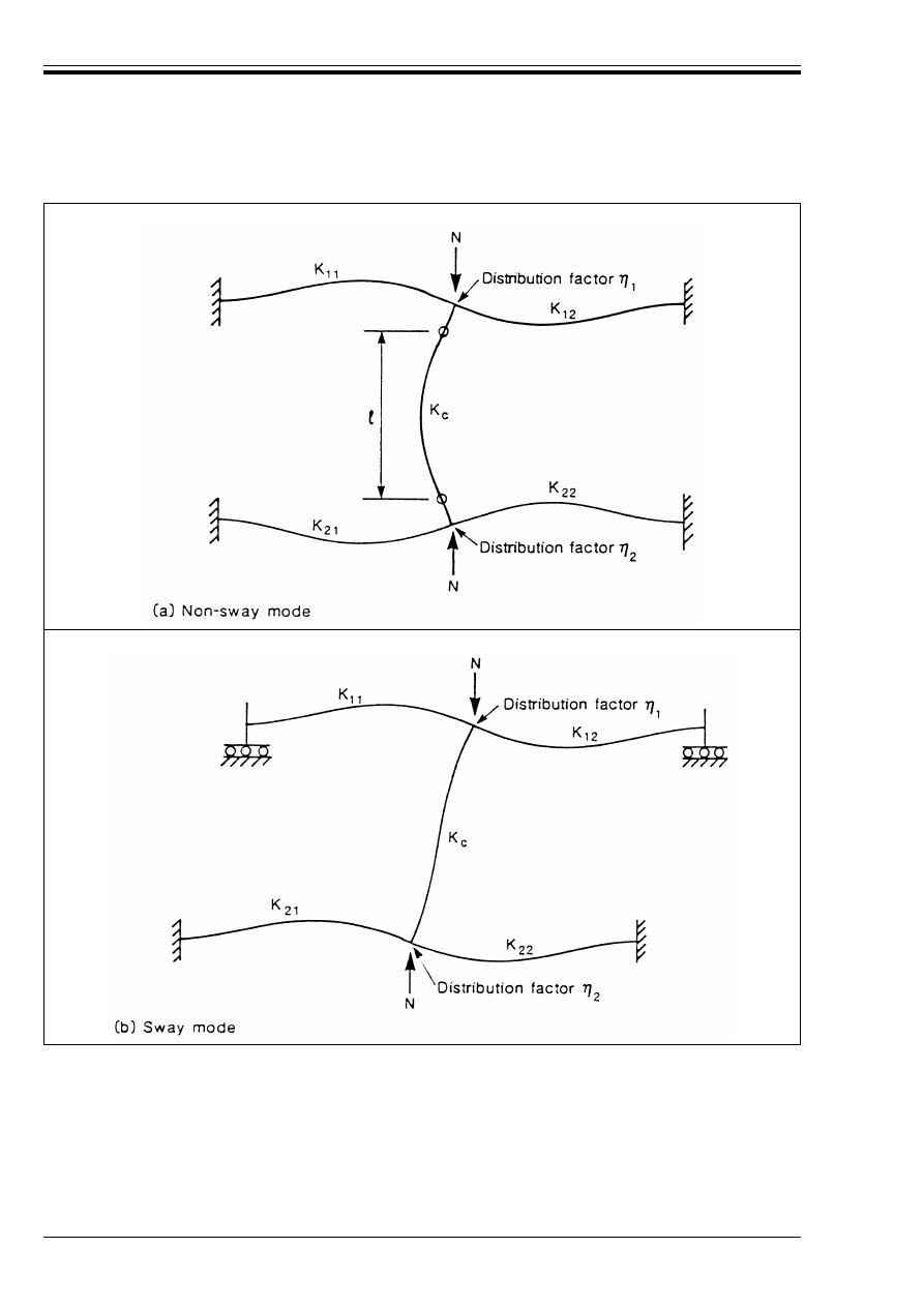
ENV 1993-1-1:1992
204
© BSI 04-2000
(6) Where the beams are not subject to axial forces, their effective stiffness coefficients may be determined
by reference to Table E.1, provided that they remain elastic under the design moments.
Figure E.2.3 — Distribution factors for columns
ENV 1993-1-1:1992
© BSI 04-2000
205
Table E.1 — Effective stiffness coefficient for a beam
(7) For building frames with concrete floor slabs, provided that the frame is of regular layout and the loading
is uniform, it is normally sufficiently accurate to assume that the effective stiffness coefficients of the beams
are as shown in Table E.2.
Table E.2 — Effective stiffness coefficient for a beam
in a building frame with concrete floor slabs
(8) Where, for the same load case, the design moment in any of the beams exceeds W
e
=
f
y
/¾
M0
, the beam should
be assumed to be pinned at the point or points concerned.
(9) Where a beam has nominally pinned connections, it should be assumed to be pinned at the point or points
concerned.
(10) Where a beam has semi-rigid connections, its effective stiffness coefficient should be reduced
accordingly.
(11) Where the beams are subject to axial forces, their effective stiffness coefficients should be adjusted
accordingly. Stability functions may be used. As a simple alternative, the increased stiffness coefficient due
to axial tension may be neglected and the effects of axial compression may be allowed for by using the
conservative approximations given in Table E.3.
Conditions of rotational restraint at far
end of beam
Effective beam stiffness coefficient K
(provided that beam remains elastic)
Fixed at far end
1,0 l/L
Pinned at far end
0,75 l/L
Rotation as at near end (double curvature) 1,5 l/L
Rotation equal and opposite to that at near
end (single curvature)
0,5 l/L
General case. Rotation Ú
a
at near end
and Ú
b
at far end
(1 + 0,5 Ú
b
/Ú
a
) l/L
Loading conditions for the beam
Non-sway mode
Sway mode
Beams directly supporting
concrete floor slabs
1,0 l/L
1,0 l/L
Other beams with direct loads
0,75 l/L
1,0 l/L
Beams with end moments only
0,5 l/L
1,5 l/L
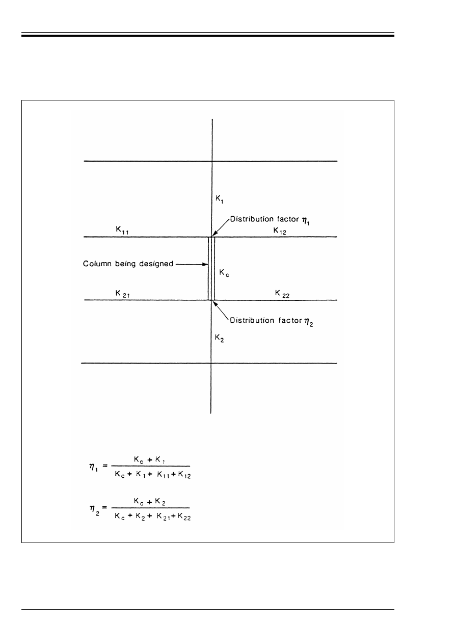
ENV 1993-1-1:1992
206
© BSI 04-2000
Figure E.2.4 — Distribution factors for continuous columns
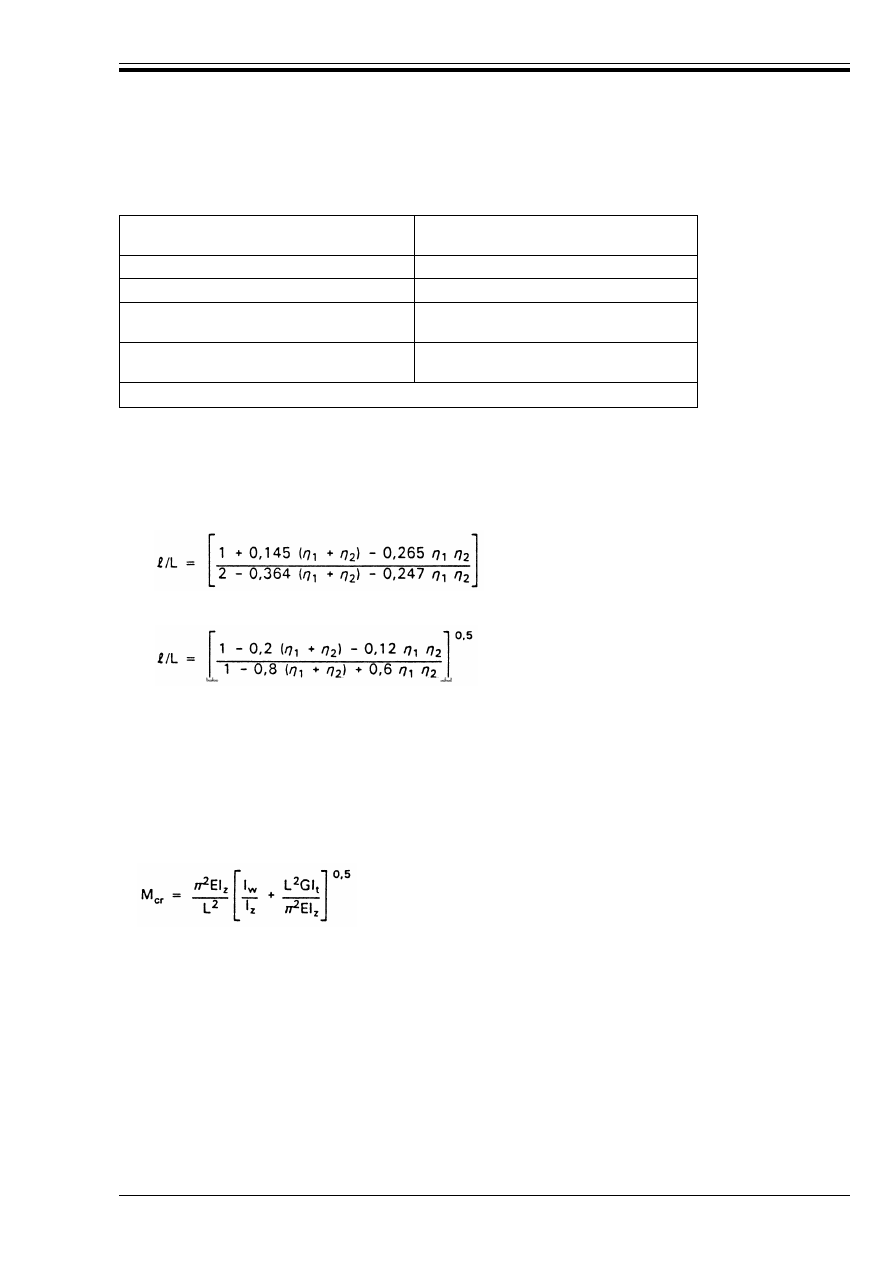
ENV 1993-1-1:1992
© BSI 04-2000
207
Table E.3 — Approximate formulae for reduced beam stiffness
coefficients due to axial compression
(12) The following empirical expressions may be used as conservative approximations instead of reading
values from Figure E.2.1 and Figure E.2.2:
a) non-sway mode (Figure E.2.1)
or alternatively:
b) sway mode (Figure E.2.2)
Annex F (informative)
Lateral torsional buckling
F.1 Elastic critical moment
F.1.1 Basis
(1) The elastic critical moment for lateral-torsional buckling of a beam of uniform symmetrical
cross-section with equal flanges, under standard conditions of restraint at each end, loaded through its
shear centre and subject to uniform moment is given by:
(2) The standard conditions of restraint at each end are:
• restrained against lateral movement
• restrained against rotation about the longitudinal axis
• free to rotate in plan
Conditions of rotational restraint at
far end of beam
Effective beam stiffness coefficient K
(provided that beam remains elastic)
Fixed
1,0 l/L (1 – 0,4 N/N
E
)
Pinned
0,75 l/L (1 – 1,0 N/N
E
)
Rotation as at near end
(double curvature)
1,5 l/L (1 – 0,2 N/N
E
)
Rotation equal and opposite to that at
near end (single curvature)
0,5 l/L (1 – 1,0 N/N
E
)
In this table N
E
= Ï
2
El/L
2
=/L = 0,5 + 0,14 (½
1
+ ½
2
) + 0,055 (½
1
+ ½
2
)
2
(E.5)
(E.6)
(E.7)
(F.1)
where
I
t
is the torsion constant
I
w
is the warping constant
I
z
is the second moment of area about the minor axis
and
L is the length of the beam between points which have lateral restraint.
G
E
2 1 v
+
(
)
---------------------
=
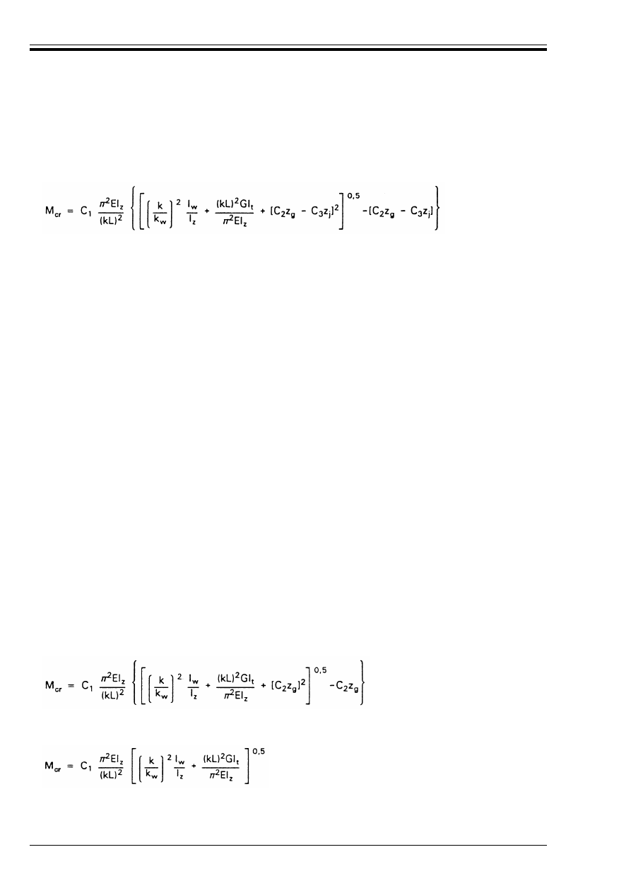
ENV 1993-1-1:1992
208
© BSI 04-2000
F.1.2 General formula for cross-sections symmetrical about the minor axis
(1) In the case of a beam of uniform cross-section which is symmetrical about the minor axis, for bending
about the major axis the elastic critical moment for lateral-torsional buckling is given by the general
formula:
where C
1
, C
2
and C
3
are factors depending on the loading and end restraint conditions
k and k
w
are effective length factors
z
g
= z
a
– z
s
z
j
= z
s
– 0,5 \
A
(y
2
+ z
2
) z dA/I
y
NOTE See F.1.2(7) and (8) for sign conventions and F.1.4(2) for approximations for z
j
(2) The effective length factors k and k
w
vary from 0,5 for full fixity to 1,0 for no fixity, with 0,7 for one end
fixed and one end free.
(3) The factor k refers to end rotation on plan. It is analogous to the ratio =/L for a compression member.
(4)The factor k
w
refers to end warping. Unless special provision for warping fixity is made, k
w
should be
taken as 1,0.
(5) Values of C
1
, C
2
and C
3
are given in Table F.1.1 and Table F.1.2 for various load cases, as indicated by
the shape of the bending moment diagram over the length L between lateral restraints. Values are given
corresponding to various values of k.
(6) For cases with k = 1,0 the value of C
1
for any ratio of end moment loading as indicated in Table F.1.1, is
given approximately by:
(7) The sign convention for determining z
j
, see Figure F.1.1, is:
• z is positive for the compression flange
• z
j
is positive when the flange with the larger value of I
z
is in compression at the point of largest
moment.
(8) The sign convention for determining z
g
is:
• for gravity loads z
g
is positive for loads applied above the shear centre
• in the general case z
g
is positive for loads acting towards the shear centre from their point of
application.
F.1.3 Beams with uniform doubly symmetric cross-sections
(1) For doubly symmetric cross-sections z
j
= 0, thus:
(2) For end-moment loading C
2
= 0 and for transverse loads applied at the shear centre z
g
= 0. For these
cases:
(F.2)
z
a
is the coordinate of the point of load application
z
s
is the coordinate of the shear centre
C
1
= 1,88 – 1,40 Ò + 0,52Ò
2
but C
1
k 2,70
(F.3)
(F.4)
(F.5)
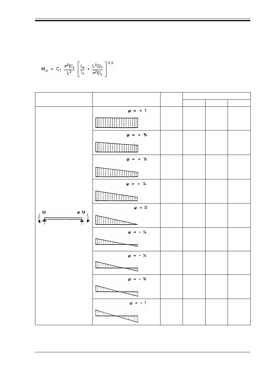
ENV 1993-1-1:1992
© BSI 04-2000
209
(3) When k = k
w
= 1,0 (no end fixity):
Table F.1.1 — Values of factors C
1
, C
2
and C
3
corresponding to values of factor k: End
moment loading
(F.6)
Loading and support
conditions
Bending moment diagram
Value of k
Values of factors
C
1
C
2
C
3
1,0
0,7
0,5
1,000
1,000
1,000
—
1,000
1,113
1,144
1,0
0,7
0,5
1,141
1,270
1,305
—
0,998
1,565
2,283
1,0
0,7
0,5
1,323
1,473
1,514
—
0,992
1,556
2,271
1,0
0,7
0,5
1,563
1,739
1,788
—
0,977
1,531
2,235
1,0
0,7
0,5
1,879
2,092
2,150
—
0,939
1,473
2,150
1,0
0,7
0,5
2,281
2,538
2,609
—
0,855
1,340
1,957
1,0
0,7
0,5
2,704
3,009
3,093
—
0,676
1,059
1,546
1,0
0,7
0,5
2,927
3,009
3,093
—
0,366
0,575
0,837
1,0
0,7
0,5
2,752
3,063
3,149
—
0,000
0,000
0,000
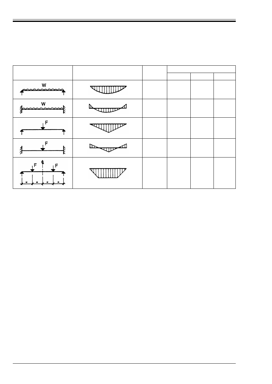
ENV 1993-1-1:1992
210
© BSI 04-2000
Table F.1.2 — Values of factors C
1
, C
2
and C
3
corresponding to values of factor k:
Transverse loading cases
Loading and support
conditions
Bending moment diagram
Values of k
Values of factors
C
1
C
2
C
3
1,0
0,5
1,132
0,972
0,459
0,304
0,525
0,980
1,0
0,5
1,285
0,712
1,562
0,652
0,753
1,070
1,0
0,5
1,365
1,070
0,553
0,432
1,730
3,050
1,0
0,5
1,565
0,938
1,267
0,715
2,640
4,800
1,0
0,5
1,046
1,010
0,430
0,410
1,120
1,890
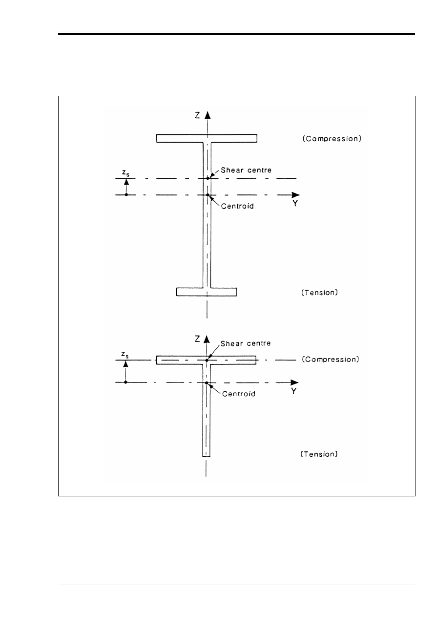
ENV 1993-1-1:1992
© BSI 04-2000
211
Figure F.1.1 — Sign convention for determining z
j
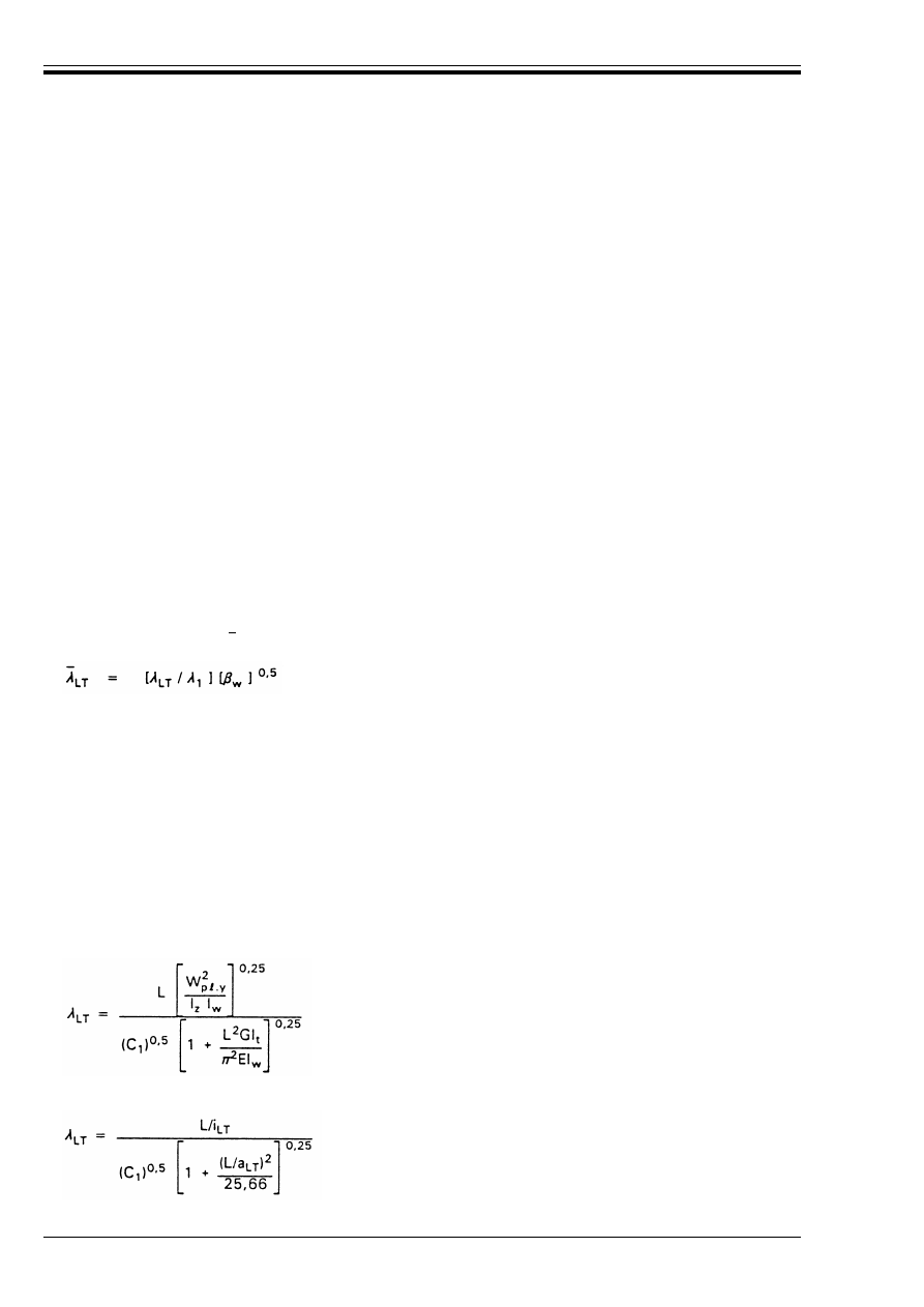
ENV 1993-1-1:1992
212
© BSI 04-2000
F.1.4 Beams with uniform monosymmetric cross-sections with unequal flanges
(1) For an I-section with unequal flanges:
(2) The following approximations for z
j
can be used:
F.2 Slenderness
F.2.1 General
(1) The slenderness ratio for lateral-torsional buckling is given by:
(2) The geometrical slenderness ratio Æ
LT
for lateral-torsional buckling is given for all classes of
cross-section, by:
F.2.2 Beams with uniform doubly symmetric cross-sections
(1) For cases with z
g
= 0 (end-moment loading or transverse loads applied at the shear centre) and
k = kw = 1,0 (no end fixity), the value of 2
LT
can be obtained from:
which can also be written:
where a
LT
= (I
w
/I
t
)
0.5
I
w
= 
f
(1 – 
f
) I
z
h
s
2
(F.7)
where 
f
=
I
fc
is the second moment of area of the compression flange about the minor axis of the section
I
ft
is the second moment of area of the tension flange about the minor axis of the section
and h
s
is the distance between the shear centres of the flanges.
when 
f
> 0,5:
z
j
= 0,8 (2
f
Ð 1) h
s
s
/2
(F.8)
when 
f
< 0,5:
z
j
= 1,0 (2
f
Ð 1) h
s
s
/2
(F.9)
for sections with a lipped compression flange:
z
j
= 0,8 (2
f
Ð 1) (1 + h
L
/h) h
s
/2 when 
f
> 0,5
(F.10)
z
j
= 1,0 (2
f
Ð 1) (1 + h
L
/h) h
s
/2 when 
f
< 0,5
(F.11)
where h
L
is the depth of the lip
(F.12)
where Æ
1
= Ï [E/f
y
]
0.5
= 93,9 ¼
¼
= [235/f
y
]
0,5
(f
y
in N/mm
2
)
w
= 1 for Class 1 or Class 2 cross-sections
w
= W
e
=
.y
/W
p
=
.y
for Class 3 cross-sections
and
w
= W
eff.y
/W
p
=
.y
for Class 4 cross sections
Æ
LT
= [Ï
2
EW
p
=
.y
/M
cr
]
0,5
(F.13)
(F.14)
(F.15)
I
fc
I
fc
I
ft
+
-------------------
Æ
LT
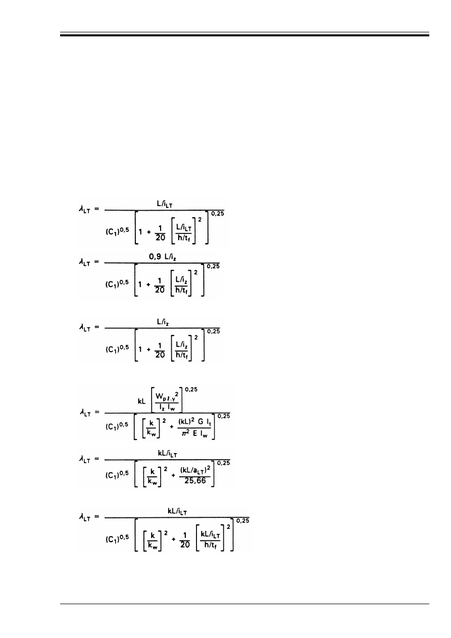
ENV 1993-1-1:1992
© BSI 04-2000
213
(2) For a plain I or H section (without lips):
where h
s
= h – t
f
(3) For a doubly symmetric cross-section, the value of i
LT
is given by:
or with a slight approximation by:
(4) For rolled I or H sections conforming with Reference Standard 2, the following conservative
approximations can be used:
(5) For any plain I or H section with equal flanges, the following approximation is conservative:
(6) Cases with k < 1,0 and/or k
w
< 1,0 can be included by using:
or for standard rolled I or H sections:
I
w
= I
z
h
s
2
/4
(F.16)
i
LT
= [I
z
I
w
/W
p
=
.y
2
]
0,25
(F.17)
i
LT
= [I
z
/(A – 0,5 t
w
h
s
)]
0,5
(F.18)
(F.19)
or
(F.20)
(F.21)
(F.22)
or
(F.23)
(F.24)
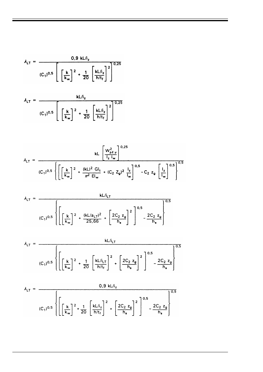
ENV 1993-1-1:1992
214
© BSI 04-2000
or for any plain I or H section with equal flanges:
(7) Unless special provision for warping fixity is made, k
w
should be taken as 1,0.
(8) Cases with transverse loading applied above the shear centre (z
g
> 0,0) or below the shear centre (z
g
< 0,0)
can be included by using:
or alternatively:
or for standard rolled I or H sections:
or alternatively:
or
(F.25)
(F.26)
(F.27)
(F.28)
(F.29)
(F.30)
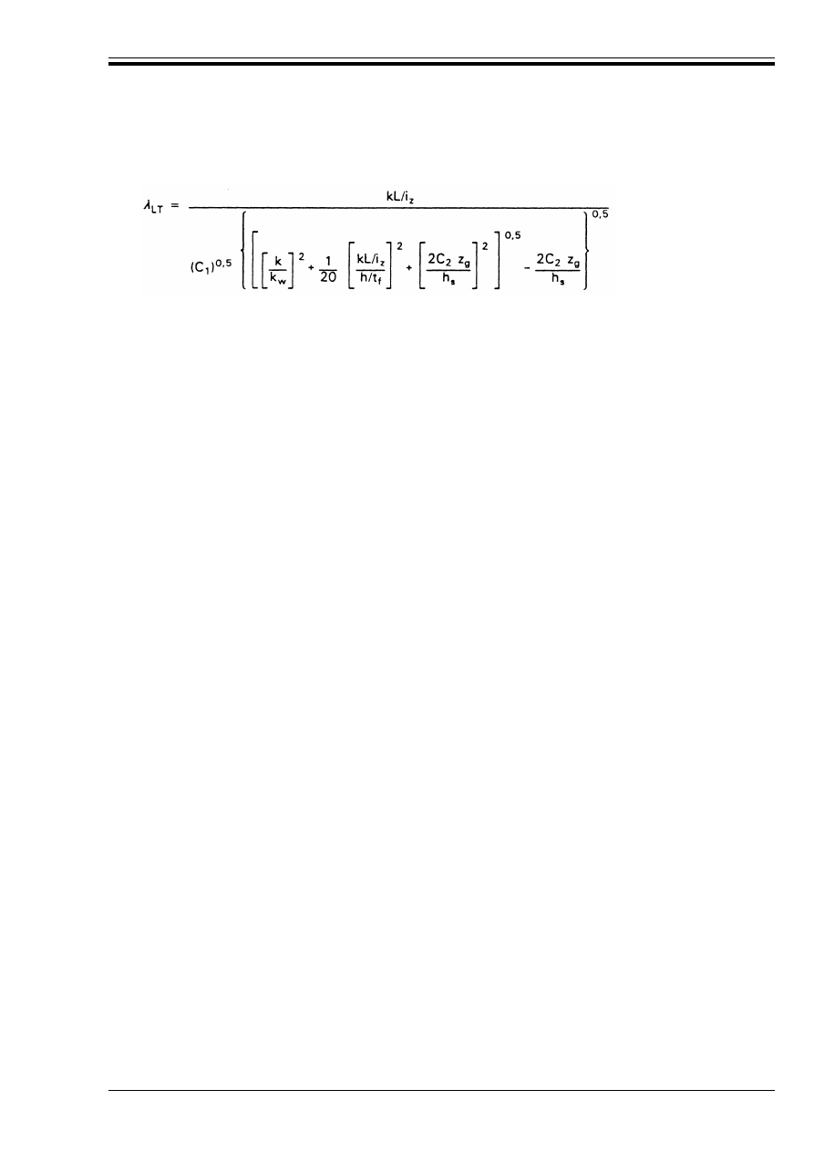
ENV 1993-1-1:1992
© BSI 04-2000
215
or for any plain I or H section with equal flanges:
Annex J (normative)
Beam-to-column connections
J.1 Scope
J.1.1 Types of connections covered
(1) This Annex gives application rules for the design of beam-to-column connections, following the principles
given section 6.9.
(2) Both the beam and the column are assumed to be I or H sections.
(3) The beam is assumed to be connected to the flange of the column.
(4) The types of connections covered are shown in Figure J.1.1 as follows:
• Welded connections.
• Bolted connections with extended end plates.
• Bolted connections with flush end plates.
(5) The column web may have:
• Stiffeners in line with both flanges of the beam.
• Stiffeners in line with one flange of the beam.
• No stiffeners in line with the beam flanges.
(6) In addition, the column web may be reinforced by:
• Diagonal stiffeners.
• A supplementary web plate.
(7) In bolted connections, column flanges may be reinforced by the use of backing plates.
(8) Methods are given for the determination of the following characteristics of a beam-to-column connection:
• Moment resistance.
• Rotational stiffness.
• Rotation capacity.
J.1.2 Other types of connection
(1) The methods given in this Annex can also be applied to beam-to-beam connections.
(2) Parts of the methods can also be applied to the relevant parts of other types of connections.
(3) These application rules do not cover connections in which the beam is to be connected to the web of the
column.
(4) These application rules should not be applied to members with sections other than I or H sections.
(F.31)
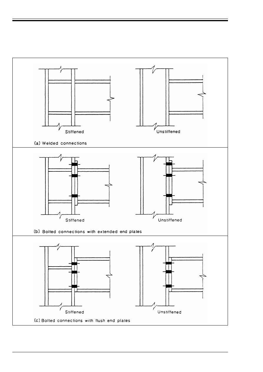
ENV 1993-1-1:1992
216
© BSI 04-2000
Figure J.1.1 — Beam-to-column connections

ENV 1993-1-1:1992
© BSI 04-2000
217
J.2 Welded beam-to-column connections
J.2.1 Moment resistance
(1) The moment resistance of a welded beam-to-column connection depends on:
• the resistance of the tension zone (see J.2.3)
• the resistance of the compression zone (see J.2.4)
• the resistance of the shear zone (see J.2.5).
J.2.2 Supplementary web plates
(1) A supplementary web plate, see Figure J.2.1, may be used to increase the resistance of a column web in:
• tension, see J.2.3.2
• compression, see J.2.4.1
• shear, see J.2.5.1.
(2) The steel grade of the supplementary web plate should be similar to that of the column.
(3) The breadth b
s
should be such that the welds connecting the supplementary web plate extend to the toe of
the root radius, see Figure J.2.1.
(4) The length =
s
should be such that the supplementary web plate extends throughout the effective width of
web in tension and compression, see Figure J.2.1.
(5) The thickness t
s
should be not less than the column web thickness t
wc
.
(6) The supplementary web plate should be welded all round (see Figure J.2.1). The welds should have a
throat thickness a as follows:
a) where the supplementary web plate is required to increase the resistance of the web to shear or
compression:
b) where the supplementary web plate is required to increase the resistance of the web to tension,
see J.2.3.2(4):
• longitudinal butt welds:
• transverse welds and longitudinal fillet welds:
a Ut
s
/Æ2
(J.1)
a Ut
s
(J.2)
a Ut
s
/Æ2
(J.3)
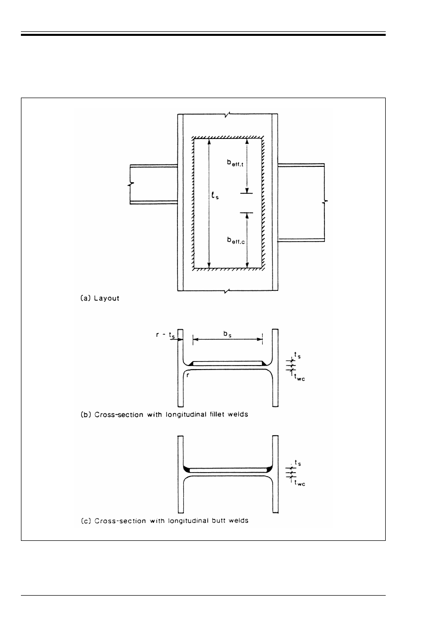
ENV 1993-1-1:1992
218
© BSI 04-2000
Figure J.2.1 — Supplementary web plate

ENV 1993-1-1:1992
© BSI 04-2000
219
(7) When the breadth b
s
of a supplementary web plate exceeds 40¼t
s
, a row of plug welds or bolts should be
used to ensure proper co-operation between the supplementary web plate and the column web,
see Figure J.2.2. The following requirements apply:
e
1
k 40¼t
s
e
2
k 40¼t
s
p k 40¼t
s
d
o
U t
s
J.2.3 Resistance of tension zone
J.2.3.1 Unstiffened column flange
(1) The design resistance of the unstiffened flange of a column subject to a transverse tensile force
(see Figure J.2.3) is given by:
• for a rolled I or H section column:
• for a welded I or H section column:
(2) If the design resistance F
t.Rd
obtained from (1) does not satisfy the following condition, the joint should
be stiffened:
where b
fb
is the width of the beam flange.
(3) The welds connecting the beam flange to the column should be designed to develop the full design
resistance of the beam flange f
yb
t
fb
b
fb
/¾
M0
.
where e
1
is the end distance of the holes
e
2
is the edge distance of the holes
p
is the pitch of the holes
d
o
is the diameter of the holes
and
¼
= [235/f
y
]
0,5
(f
y
in N/mm
2
)
F
t.Rd
= [f
yb
t
fb
(t
wc
+ 2r
c
) + 7 f
yc
t
fc
2
]/¾
M0
(J.4)
but F
t.Rd
k f
yb
t
fb
[t
wc
+ 2r
c
+ 7 t
fc
]/¾
M0
(J.5)
F
t.Rd
= [f
yb
t
fb
(t
wc
+ 2 Æ2 a
c
) + 7 f
yc
t
fc
2
]/¾
M0
(J.6)
but F
t.Rd
k f
yb
t
fb
[t
wc
+ 2 Æ2 a
c
+ 7 t
fc
]/¾
M0
(J.7)
F
t.Rd
U 0,7 f
yb
t
fb
b
fb
/¾
M0
(J.8)
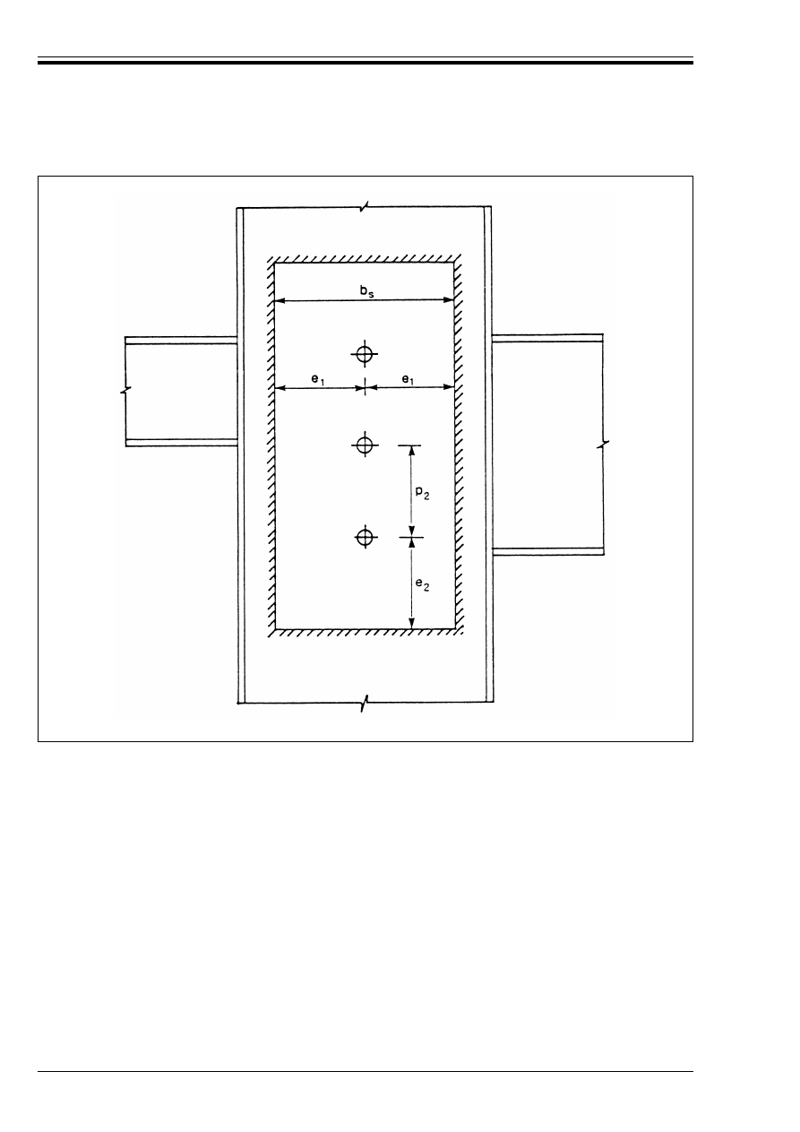
ENV 1993-1-1:1992
220
© BSI 04-2000
Figure J.2.2 — Spacing of plug welds or bolts for supplementary web plate
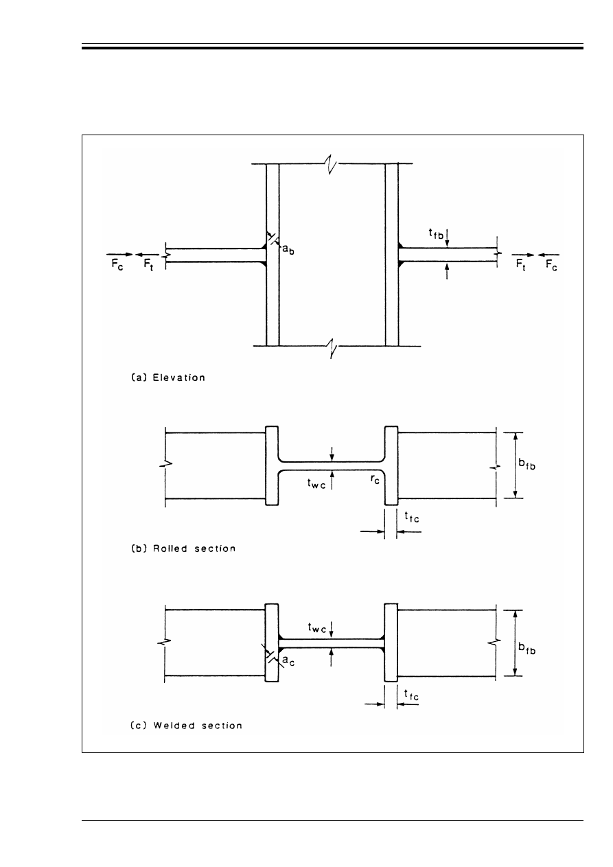
ENV 1993-1-1:1992
© BSI 04-2000
221
J.2.3.2 Unstiffened column web
(1) The design resistance of an unstiffened column web subject to a transverse tensile force is given by:
Figure J.2.3 — Transverse force on an unstiffened column
F
t.Rd
= f
yc
t
wc
b
eff
/¾
M0
(J.9)

ENV 1993-1-1:1992
222
© BSI 04-2000
(2) In a welded connection, the effective width of the column web, see Figure J.2.3, is given by:
• for a rolled I or H section column:
• for a welded I or H section column:
(3) An unstiffened column web may be strengthened by adding a supplementary web plate, see J.2.2.
(4) The design tension resistance of a column web with a supplementary web plate conforming with J.2.2
depends on the throat thickness of the longitudinal welds connecting the supplementary web plate,
see J.2.2(6) b). The effective thickness of the web t
w.eff
may be taken as follows:
• when the longitudinal welds are butt welds with a throat thickness a U t
s
:
• with one supplementary web plate:
• with supplementary web plates both sides:
• when the longitudinal welds are fillet welds with a throat thickness a U t
s
/Æ2, then for either one or
two supplementary web plates:
J.2.3.3 Stiffened column
(1) The design resistance of a stiffened column subject to a transverse tensile force is at least equal to the
design resistance of the beam flange, provided that the stiffeners meet the following requirements:
a) The thickness of the stiffeners should not be smaller than the flange thickness of the beam.
b) If the steel grade of the stiffeners is lower than that of the beam, the adequacy of the stiffeners to resist
the transverse forces applied by the beam flanges should also be verified.
c) The welds between the stiffeners and the column flanges should be designed to resist the transverse
forces applied by the beam flanges.
d) The welds between the stiffeners and the column web should be designed to resist the forces to be
transferred into the column web from the beam flanges.
J.2.4 Resistance of compression zone
J.2.4.1 Unstiffened column web
(1) The design crushing resistance of an unstiffened column web subject to a transverse compression force is
given by:
(2) In a welded connection, the effective width of the column web, see Figure J.2.3, is given by:
• for a rolled I or H section column:
• for a welded I or H section column:
(3) In addition the resistance of the column web to buckling in a column mode, as indicated in Figure J.2.4,
should be verified using 5.7.5.
(4) The sway mode shown in Figure J.2.4(b) should normally be prevented by constructional restraints.
(5) An unstiffened column web may be strengthened by adding a supplementary web plate conforming
with J.2.2.
b
eff
= t
fb
+ 2 Æ2 a
b
+ 5(t
fc
+ r
c
)
(J.10)
b
eff
= t
fb
+ 2 Æ2 a
b
+ 5(t
fc
+ Æ2 a
c
)
(J.11)
t
w.eff
= 1,5t
wc
(J.12)
t
w.eff
= 2,0t
wc
(J.13)
t
w.eff
= 1,4t
wc
(J.14)
F
c.Rd
= f
yc
t
wc
[1,25 – 0,5 ¾
M0
Ö
n.Ed
/f
yc
] b
eff
/¾
M0
(J.15)
but
F
c.Rd
k f
yc
t
wc
b
eff
/¾
M0
(J.16)
where Ö
n.Ed
is the maximum compressive normal stress in the web of the column due to axial force and
bending.
b
eff
= t
fb
+ 2 Æ2 a
b
+ 5 (t
fc
+ r
c
)
(J.10)
b
eff
= t
fb
+ 2 Æ2 a
b
+ 5 (t
fc
+ Æ2 a
c
)
(J.11)
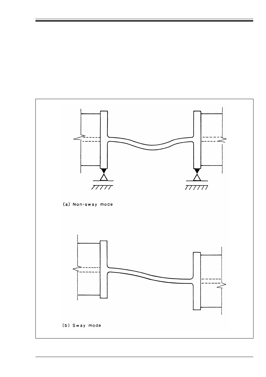
ENV 1993-1-1:1992
© BSI 04-2000
223
(6) In calculating the design crushing resistance of a column web with a supplementary web plate, the
effective thickness of the web may be taken as 1,5t
wc
when one supplementary web plate is added or 2,0t
wc
when supplementary web plates are added both sides of the web.
J.2.4.2 Stiffened column web
(1) The design resistance of a stiffened column web subject to a transverse compression force is at least equal
to the design resistance of the beam flange, provided that the stiffeners meet the requirements specified
in J.2.3.3(1).
Figure J.2.4 — Column buckling modes of an unstiffened web

ENV 1993-1-1:1992
224
© BSI 04-2000
J.2.5 Resistance of shear zone
J.2.5.1 Unstiffened column web panel
(1) The design plastic shear resistance of an unstiffened column web panel subject to a shear force
(see Figure J.2.5) is given by:
where A
v
is the shear area of the column as given in 5.4.6(2).
(2) In addition the shear buckling resistance should be checked, if necessary, see 5.4.6(7).
(3) An unstiffened column web can be strengthened by adding a supplementary web plate conforming
with J.2.2.
(4) In calculating the design shear resistance of a web panel with a supplementary web plate, its shear area
A
v
may be increased by b
s
t
wc
. No further increase in A
v
should be made if supplementary web plates are
added both sides of the web.
J.2.5.2 Stiffened column web panel
(1) When diagonal web stiffeners (see Figure J.2.6) are used to increase the shear resistance of a column web,
they should be designed to resist the tensile and compressive forces transmitted to the column by the flanges
of the beams.
(2) The welds between the stiffeners and the column flanges should be designed to resist the forces in the
stiffeners.
(3) The welds between the stiffeners and the column web should be treated as nominal.
V
p
=
.Rd
= [f
yc
A
v
/Æ3]/¾
M0
(J.17)
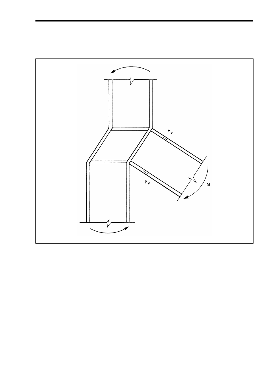
ENV 1993-1-1:1992
© BSI 04-2000
225
Figure J.2.5 — Unstiffened column web panel subject to a shear force
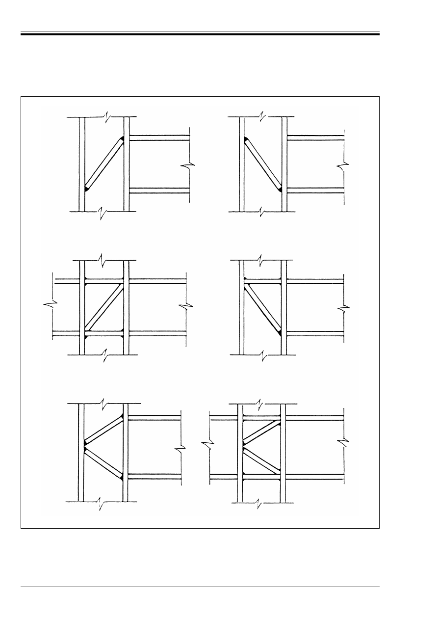
ENV 1993-1-1:1992
226
© BSI 04-2000
Figure J.2.6 — Column web panels with diagonal stiffeners
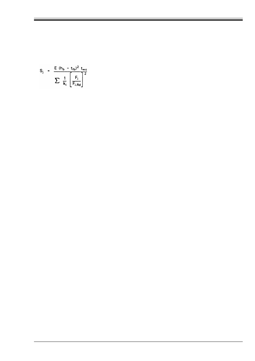
ENV 1993-1-1:1992
© BSI 04-2000
227
J.2.6 Rotational stiffness
(1) The rotational stiffness of a welded beam-to-column connection may be obtained from:
(2) In an unstiffened welded connection, the stiffness factors k
i
should be taken as follows:
(3) For any stiffened component, the relevant stiffness factor k
i
should be taken as infinity.
(4) A welded connection in which the column web is stiffened in both the tension zone and the compression
zone may be assumed to be a rigid connection (see 6.4.2.2).
J.2.7 Rotation capacity
(1) An unstiffened welded beam-to-column connection, designed in conformity with the application rules
given in this annex, may be assumed to have a rotation capacity Ì
Cd
of 0,015 radians.
(2) A full-strength welded beam-to-column connection may be assumed to have adequate rotation capacity
for plastic analysis.
(3) A welded beam-to-column connection in which the moment resistance is governed by the resistance of the
shear zone may be assumed to have adequate rotation capacity for plastic analysis.
(4) A welded beam-to-column connection in which the column is stiffened in both the tension zone and the
compression zone may be assumed to have adequate rotation capacity for plastic analysis, even if it is not
full-strength.
(5) A welded beam-to-column connection in which the column is stiffened in the tension zone but not in the
compression zone, may be assumed to have adequate rotation capacity for plastic analysis.
(6) In a welded beam-to-column connection in which the column is stiffened in the compression zone but not
in the tension zone, when the moment resistance is not governed by the resistance of the shear zone, see (3)
above, the rotation capacity Ì
Cd
may be determined from:
J.3 Bolted beam-to-column connections
J.3.1 Limitations
(1) In section J.3 the following limitations apply:
• All bolted beam-to-column connections are assumed to have only 2 bolts in each bolt-row.
• The projecting portion of an extended end plate is assumed to have only one row of bolts.
• The projecting portion of an extended end plate is assumed to be unstiffened.
(2) Parts of the methods given in section J.3 can also be applied to the relevant parts of other types of
connection.
(3) The predicted rotational stiffness at the serviceability limit state is reasonably accurate, but the predicted
rotational stiffness at the ultimate limit state is low in some cases.
(J.18)
where
S
j
is the secant stiffness with respect to a particular moment M in the connection (M k M
Rd
)
k
i
is the stiffness factor for component i
F
i
is the force in component i of the connection due to the moment M, but not less
than F
i.Rd
/1,5.
F
i.Rd
is the design resistance of component i of the connection
Column web, shear zone:
k
1
= 0,24
Column web, tension zone:
k
2
= 0,8
Column web, compression zone:
k
3
= 0,8
Ì
Cd
= 0,025h
c
/h
b
(J.19)

ENV 1993-1-1:1992
228
© BSI 04-2000
J.3.2 Moment resistance
(1) The moment resistance of a bolted beam-to-column connection depends on:
• The resistance of the tension zone, see J.3.4.
• The resistance of the compression zone, see J.3.5.
• The resistance of the shear zone, see J.3.6.
(2) Except as specified in (3), the moment resistance of a bolted beam-to-column connection should be
obtained using Procedure J.3.1.
(3) The moment resistance of a bolted beam-to-column connection which is required to be full strength, may
also be determined by using Procedure J.3.1 or alternatively by using Procedure J.3.2.
Procedure J.3.1
Sheet 1
Moment resistance of a bolted beam-to-column connection — plastic distribution of bolt forces.
(1)
Determine the potential resistance of the column flange in the tension zone, see J.3.4.1 to J.3.4.3.
(2)
Determine the potential resistance of the beam end plate in the tension zone, see J.3.4.4.
(3)
Using the values obtained in Steps (1) and (2), obtain the effective resistance for each individual
row of bolts in the tension zone, see J.3.4.5.
(4)
Except in the case of a full-strength connection, if the design value of the effective resistance for
any individual bolt-row exceeds 1,8B
t.Rd
, where B
t.Rd
is as given in J.3.3(3), change the design of the
connection (for example by using stronger bolts), unless it can be shown that the effective
resistance of that bolt-row will be omitted (or reduced below 1,8B
t.Rd
) in Step (10).
(5)
From Step (3), determine the total effective resistance of all the bolt-rows in the tension zone.
(6)
Determine the resistance of the column web in the tension zone, see J.3.4.6 to J.3.4.7.
(7)
Determine the resistance of the column web in the compression zone, see J.3.5.
(8)
Determine the resistance of the column web in the shear zone, see J.3.6.
(9)
Adopt the smallest of the design values obtained in Steps (5) to (8) as the resistance of the weakest
zone.
(10) If the total of the effective resistance of the bolt-rows in the tension zone obtained in Step (5) is
greater than the resistance of the weakest zone obtained in Step (9), reduce it by omitting or
reducing the effective resistances of successive bolt rows, starting with the row nearest to the
centre of compression, until the effective resistance of the remaining bolt rows is equal to the
resistance of the weakest zone.
(11) Adopt a reduced tension zone containing only those bolt rows which remain after completing
Step (10).
(12) Re-check the resistance of the column web in the reduced tension zone, see J.3.4.6 to J.3.4.7.
(13) If the value obtained in Step (12) is less than the total effective resistance of the bolt-rows in the
reduced tension zone, adopt it as the new value of the resistance of the weakest zone and return to
Step (10).
(14) Check the resistance of the tension zone of the beam web adjacent to the beam end plate in the
same way as for the column web, Step (12).
(15) If the value obtained in Step (14) is less than the total effective resistance of the bolt-rows in the
reduced tension zone, adopt it as the new value of the resistance of the weakest zone and return to
Step (10).

ENV 1993-1-1:1992
© BSI 04-2000
229
Procedure J.3.1
Sheet 2
(16) Determine the design value of the moment resistance of the connection M
Rd
based on the bolt-rows
in the reduced tension zone, from:
M
Rd
= C [F
ti.Rd
h
i
]
(J.20)
where
F
ti.Rd
is the design value of the effective resistance of an individual row of bolts
and
h
i
is the distance from that bolt-row to the centre of resistance of the compression
zone.
(17) Ensure that the resistance of the welds between the beam flange and the end plate
satisfies J.3.4.4(6).

ENV 1993-1-1:1992
230
© BSI 04-2000
Procedure J.3.2
Sheet 1
Moment resistance of a bolted beam-to-column connection — distribution of bolt forces proportional to
distance from centre of compression.
(1)
Adopt a distribution of bolt forces in which the resistance of each individual bolt-row in the tension
zone of the compression zone and the maximum bolt-row force is 2,0B
t.Rd
, where B
t.Rd
is as given
in J.3.3(3).
(2)
Using the values from Step (1), determine the total effective resistance of all the bolt-rows in the
tension zone.
(3)
Determine the resistance of the column web in the tension zone, see J.3.4.6 to J.3.4.7.
(4)
Determine the resistance of the column web in the compression zone, see J.3.5.
(5)
Determine the resistance of the column web in the shear zone, see J.3.6.
(6)
Adopt the smallest of the design values obtained in Steps (2) to (5) as the resistance of the weakest
zone.
(7)
If the total effective resistance of all the bolt-rows in the tension zone obtained in Step (2) is
greater than the resistance of the weakest zone obtained in Step (6), reduce the force in each
individual bolt-row pro rata so that the total force for all the bolt-rows is equal to the resistance of
the weakest zone.
(8)
For the column flange, ensure that the sum of the bolt-row forces from Step (7) for each group of
bolt-rows (or for all the bolt-rows for an unstiffened flange) does not exceed 2M
p
=
.Rd
/m for the
relevant effective length of column flange from J.3.4.1 or J.3.4.3, where M
p
=
.Rd
and m are as
defined in J.3.3(3).
(9)
If necessary to satisfy Step (8), reduce the force in each individual bolt-row pro rata.
(10) For the column flange, ensure that the maximum bolt-row force from Step (9) in any bolt-row not
adjacent to a column stiffener does not exceed 2M
p
=
.Rd
/m for an effective length of column flange
equal to the lesser of 4 m + 1,25e or 2 Ïm, where e is as defined in J.3.3(3).
(11) If necessary to satisfy Step (10), reduce the force in each individual bolt-row pro rata.
(12) For the beam end plate, ensure that the sum of the bolt-row forces from Step (11) for each group of
bolt-rows does not exceed 2M
p
=
.Rd
/m for the relevant effective length of end plate from J.3.4.4,
using the relevant values of M
p
=
.Rd
and m for the end plate.
(13) If necessary to satisfy Step (12), reduce the force in each individual bolt-row pro rata.
(14) For the beam end plate, ensure that the maximum bolt-row force from Step (13) in any bolt-row not
adjacent to a stiffener or flange connected to the beam end plate, does not exceed 2M
p
=
.Rd
/m for an
effective length of end plate equal to the lesser of 4 m + 1,25e or 2 Ïm.
(15) If necessary to satisfy Step (14), reduce the force in each individual bolt-row pro rata.
(16) For the column web, ensure that the maximum bolt-row force from Step (15) in any bolt-row not
adjacent to a column stiffener does not exceed the resistance of the column web in the tension zone,
see J.3.4.6, for an effective width of column web equal to the effective length of column flange from
Step (10).
(17) If necessary to satisfy Step (16), reduce the force in each individual bolt-row pro rata.
(18) Check the resistance of the tension zone of the beam web adjacent to the beam end plate in the
same way as for the column web, see J.3.4.6 to J.3.4.7, considering both the whole of each group of
bolt-rows and the critical individual bolt-row from Step (14).
(19) If necessary to satisfy Step (18), reduce the force in each individual bolt-row pro rata.

ENV 1993-1-1:1992
© BSI 04-2000
231
Procedure J.3.2
Sheet 2
(20) Determine the design value of the moment resistance of the connection M
Rd
from:
(J.21)
where F
t1.Rd
is the design value of the effective resistance of the bolt-row farthest from the
centre of resistance of the compression zone.
h
1
is the distance from the farthest bolt-row to the centre of resistance of the
compression zone.
and
h
i
is the distance from any bolt-row to the centre of resistance of the compression
zone.
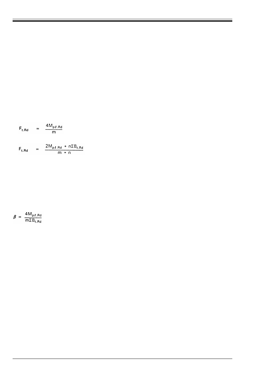
ENV 1993-1-1:1992
232
© BSI 04-2000
J.3.3 Equivalent T-stub
(1) The tension resistance of the column flange and of the beam end-plate are given in terms of equivalent T-
stubs, see Figure J.3.1.
(2) The resistance of a T-stub may be governed by:
• the resistance of the flange
• the resistance of the bolts
• the resistance of the web, and
• the resistance of the web-to-flange welds, in the case of a welded T-stub.
(3) The design tension resistance of a T-stub flange should be taken as the smallest value for the three
possible modes of the failure indicated in Figure J.3.2 as follows:
(4) The relationship between connection geometry and mode of failure is indicated in Figure J.3.3, in which:
Mode 1: Complete yielding of flange:
(J.22)
Mode 2: Bolt failure with yielding of flange:
(J.23)
Mode 3: Bolt failure only:
F
t.Rd
= CB
t.Rd
(J.24)
where M
p
=
.Rd
= 0,25=t
y
2
f
y
/¾
M0
(J.25)
B
t.Rd
is the design tension resistance of a single bolt-plate assembly, obtained from 6.5.5(4).
CB
t.Rd
is the total value for all the bolt in the T-stub.
n
= e
min
but n k 1,25 m
and =, m and e are as indicated in Figure J.3.1.
and Æ = n/m
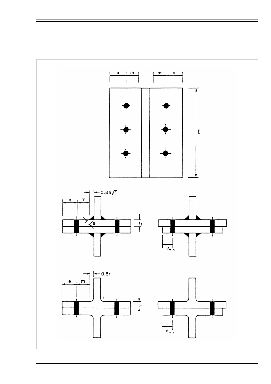
ENV 1993-1-1:1992
© BSI 04-2000
233
Figure J.3.1 — Dimensions of a T-stub
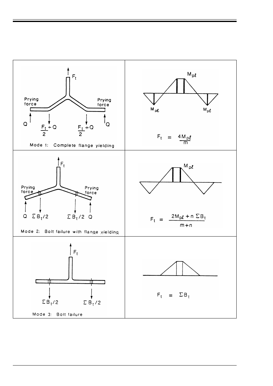
ENV 1993-1-1:1992
234
© BSI 04-2000
Figure J.3.2 — Failure modes of a T-stub flange
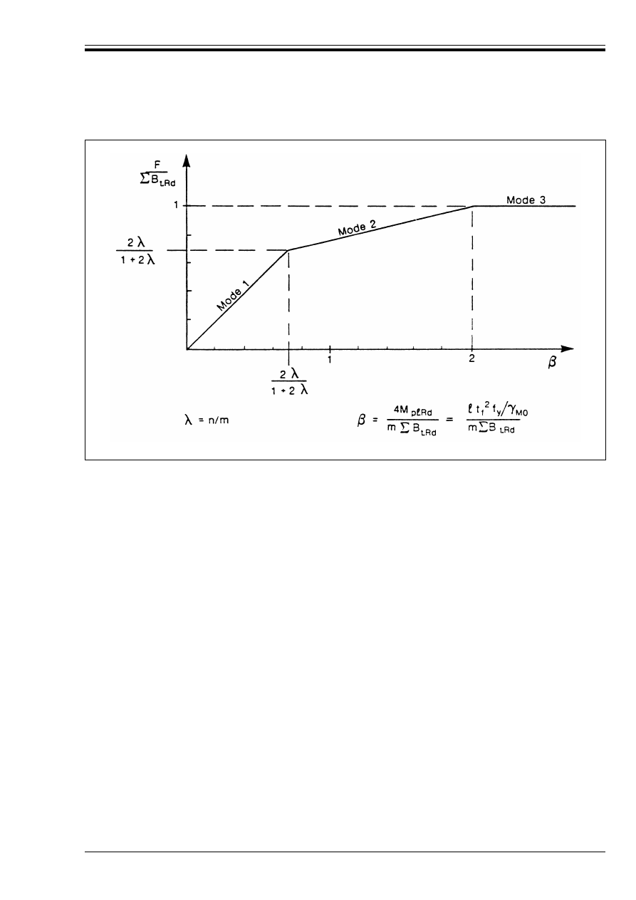
ENV 1993-1-1:1992
© BSI 04-2000
235
J.3.4 Resistance of tension zone
J.3.4.1 Unstiffened column flange
(1) The tension zone of an unstiffened column flange should be considered to act as a series of equivalent
T-stubs with a total length equal to the total effective length ×=
eff
of the bolt pattern in the tension zone of the
connection, as indicated in Figure J.3.4.
(2) The effective length =
eff
for each row of bolts should be taken as the smallest of the following values for the
respective case:
a) for inner bolts:
b) for end bolts:
(3) When the compressive normal stress Ö
n.Ed
in the column flange due to the axial force and bending moment
in the column exceeds 180 N/mm
2
at the location of the tension zone, the possible reduction of the design
moment resistance of the column flange should be allowed for by multiplying the value of M
p
=
.Rd
in J.3.3(3)
by a reduction factor k
r
obtained as follows:
• when Ö
n.Ed
k180 N/mm
2
:
k
r
= 1
• when 180 N/mm
2
< Ö
n.Ed
kf
y
:
where Ö
n.Ed
and f
y
are in N/mm
2
.
Figure J.3.3 — Effect of connection geometry on failure mode of a T-stub flange
=
eff.a
= p
[see Figure J.3.4(a)]
(J.26)
=
eff.a
= 4 m + 1,25e
[see Figure J.3.4(b)]
(J.27)
=
eff.a
= 2Ïm
[see Figure J.3.4(c)]
(J.28)
=
eff.b
= 0,5p + 2 m + 0,625e [see Figure J.3.4(a)]
(J.29)
=
eff.b
= 4 m + 1,25e
[see Figure J.3.4(b)]
(J.30)
=
eff.b
= 2Ïm
[see Figure J.3.4(c)]
(J.31)
but k
r
k 1
(J.32)
k
r
2f
y
180
–
Ö
n.Ed
–
2f
y
360
–
---------------------------------------------
=
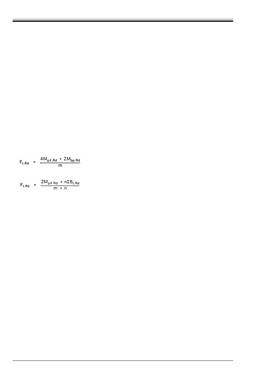
ENV 1993-1-1:1992
236
© BSI 04-2000
(4) The mode of failure and the maximum potential design resistance should be determined by considering
all the bolt-rows in the tension zone as a single group acting together in a single equivalent T-stub.
(5) For this purpose, the equivalent T-stub should be assumed to be in equilibrium with another similar
T-stub. The minimum value of e for the column flange or the beam end-plate should be used to determine n
but the actual value of e for the column flange should be used to determine =
eff
.
(6) The actual effective design resistance for each bolt row, allowing for compatibility with the tension zone
of the beam end-plate, should be determined as described in J.3.4.5.
J.3.4.2 Column flange with backing plates
(1) Column flanges may be reinforced by adding loose backing plates as indicated in Figure J.3.5.
(2) The width of a backing plate b
bp
should not be less than the distance from the edge of the flange to the toe
of the root radius or weld fillet.
(3) The length of a backing plate should not be less than the total effective length for the bolt pattern in the
tension zone of the connection and should be such that it extends not less than 2d beyond the last bolt at each
end.
(4) The design tension resistance of a column flange reinforced with backing plates, should be taken as the
smallest value for the three possible modes failure [see J.3.3(3)] as follows:
Mode 1:
Complete yielding of flange and backing plate:
(J.33)
Mode 2:
Bolt failure with yielding of flange only:
(J.23)
Mode 3:
Bolt failure only:
F
t.Rd
= CB
t.Rd
(J.24)
where M
bp.Rd
is the design moment resistance of a backing plate given by:
M
bp.Rd
= 0,25 =
eff
t
bp
2
f
y.bp
/¾
M0
(J.25)
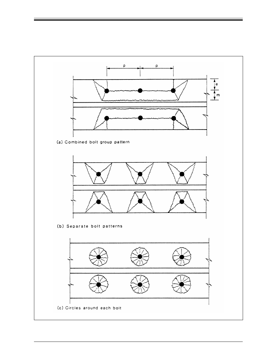
ENV 1993-1-1:1992
© BSI 04-2000
237
Figure J.3.4 — Yield line patterns for an unstiffened flange
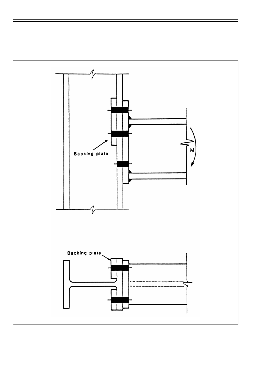
ENV 1993-1-1:1992
238
© BSI 04-2000
Figure J.3.5 — Column flange with backing plates in the tension zone

ENV 1993-1-1:1992
© BSI 04-2000
239
J.3.4.3 Stiffened column flange
(1) The tension zone of a stiffened column flange should be considered to act as a series of equivalent
T-stubs with a total length equal to the total effective length of the bolt pattern in the tension zone, as
indicated in Figure J.3.6.
(2) The effective length =
eff
for each row of bolts should be taken as the smallest of the following values for the
respective case:
a) for bolts adjacent to a stiffener:
b) for other inner bolts:
c) for other end bolts:
where the ratio µ is obtained from Figure J.3.7.
(3) When the compressive normal stress Ö
n.Ed
in the column flange due to the axial force and bending moment
in the column exceeds 180 N/mm
2
at the location of the tension zone, the reduction factor k
r
should be applied
as in J.3.4.1(3).
(4) The groups of bolt-rows each side of a stiffener should be treated as separate overlapping equivalent
T-stubs. The mode of failure and the maximum potential design resistance should be determined separately
for each such group of bolt-rows.
(5) For this purpose each equivalent T-stub should be assumed to be in equilibrium with another similar
T-stub. The minimum value of e for the column flange or the beam end plate should be used to determine n
but the actual value of e for the column flange should be used to determine =
eff
.
(6) The actual effective design resistance for each bolt row, allowing for compatibility with the tension zone
of the beam end-plate, should be determined as described in J.3.4.5.
(7) The stiffeners should meet the requirements specified in J.2.3.3(1).
=
eff.a
= µm
(J.35)
=
eff.a
= 2Ïm
(J.28)
=
eff.b
= p
(J.36)
=
eff.b
= 4m + 1,25e
(J.30)
=
eff.b
= 2Ïm
(J.31)
=
eff.c
= 0,5p + 2m + 0,625e
(J.37)
=
eff.c
= 4m + 1,25e
(J.38)
=
eff.c
= 2Ïm
(J.39)
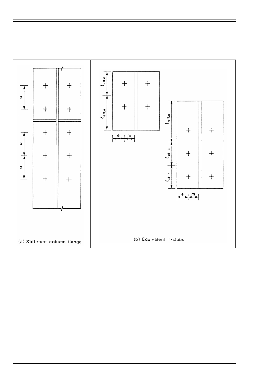
ENV 1993-1-1:1992
240
© BSI 04-2000
Figure J.3.6 — Effective lengths of equivalent T-stub flanges representing a stiffened
column flange

ENV 1993-1-1:1992
© BSI 04-2000
241
J.3.4.4 End plate
(1) The tension zone of a beam end plate should be considered to act as a series of equivalent T-stubs with a
total length equal to the total effective length of the bolt pattern in the tension zone, as indicated in
Figure J.3.8.
Figure J.3.7 — Values of µ for stiffened column flanges

ENV 1993-1-1:1992
242
© BSI 04-2000
(2) The effective length =
eff
for each row of bolts should be taken as the smallest of the following values for the
respective case:
a) for bolts outside tension flange of beam:
b) for first row of bolts below tension flange of beam:
c) for other inner bolts:
d) for other end bolts:
where the ratio µ is obtained from Figure J.3.7.
(3) The groups of bolt-rows each side of any stiffeners connected to the end plate should be treated as separate
overlapping equivalent T-stubs. In extended end plates, the groups of bolt-rows above and below the tension
flange of the beam should also be treated as separate overlapping equivalent T-stubs. The mode of failure
and the maximum potential design resistance should be determined separately for each such group of
bolt-rows.
(4) For this purpose each equivalent T-stub should be assumed to be in equilibrium with another similar
T-stub. The minimum value of e for the end plate or the column flange should be used to determine n but the
actual value of e for the end plate should be used to determine =
eff
.
(5) The actual effective design resistance for each bolt row, allowing for compatibility with the tension zone
of the column flange, should be determined as described in J.3.4.5.
(6) To ensure that the welds between the beam flange and the end plate have sufficient deformation capacity,
they should be designed to resist the effects of a moment equal to the smaller of:
• the design plastic moment resistance of the beam M
p
=
.Rd
• Y times the design moment resistance of the connection.
J.3.4.5 Effective resistance of bolt-rows
(1) The maximum potential design resistance of the column flange is generally not the same as the maximum
potential design resistance of the beam end plate.
(2) In order to determine the actual design resistance of the tension zone, a compatible distribution of
bolt-row forces should be obtained in which, for each row of bolts, there is equilibrium between its
contributions to the design resistances of the column flange and the beam end-plate.
(3) The effective design resistances for the individual bolt-rows should be obtained using Procedure J.3.3.
(4) It may be assumed that the effective design resistance for each bolt-row acts at the centre-line of that
bolt-row.
=
eff.a
= 0,5b
p
(J.40)
=
eff.a
= 0,5w + 2m
x
+ 0,625e
x
(J.41)
=
eff.a
= 4m
x
+ 1,25e
x
(J.42)
=
eff.a
= 2Ïm
x
(J.43)
=
eff.b
= µm
(J.44)
=
eff.b
= 2Ïm
(J.31)
=
eff.c
= p
(J.45)
=
eff.c
= 4m + 1,25e
(J.38)
=
eff.c
= 2Ïm
(J.39)
=
eff.d
= 0,5p + 2m + 0,625e
(J.46)
=
eff.d
= 4m + 1,25e
(J.47)
=
eff.d
= 2Ïm
(J.48)
where Y = 1,4 for a braced frame
(J.49)
or
Y = 1,7 for an unbraced frame.
(J.50)
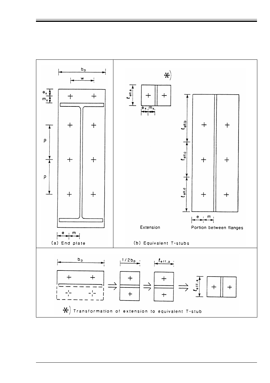
ENV 1993-1-1:1992
© BSI 04-2000
243
J.3.4.6 Unstiffened column web
(1) The design resistance of an unstiffened column web subject to a transverse tensile force is given by:
Figure J.3.8 — Effective lengths of equivalent T-stub flanges representing an end plate
F
t.Rd
= f
yc
t
wc
b
eff
/¾
M0
(J.9)

ENV 1993-1-1:1992
244
© BSI 04-2000
(2) In a bolted connection, the effective width of the column web in tension should be taken as equal to the
total effective length of the bolt pattern in the tension zone of the connection, obtained from J.3.4.1.
(3) An unstiffened column web may be strengthened by adding a supplementary web plate conforming
with J.2.2, see J.2.3.2(4).
J.3.4.7 Stiffened column web
(1) The design resistance of a stiffened column web subject to a transverse tensile force is at least equal to the
design resistance of the beam flange, provided that the stiffeners meet the requirements specified
in J.2.3.3(1).
Procedure J.3.3
Effective design resistances for bolt-rows.
(1)
Recalculate the potential design resistance of a column flange, successively omitting the lowest
bolt-row. For a stiffened column flange, recalculate the potential design resistance separately for
each relevant group of bolt-rows.
(2)
Recalculate the potential design resistance of each group of bolt-rows in the beam end-plate,
successively omitting the lowest bolt-row.
(3)
Take the reduction in resistance due to the omission of a bolt-row in Steps (1) and (2) as its
contribution to the total potential design resistance of the flange or end-plate.
(4)
For each bolt-row, determine the difference between the potential design resistances of the column
flange and the beam end-plate, obtained in Step (3).
(5)
Starting from the highest bolt-row, redistribute the resistance values from Step (3) to minimise the
differences found in Step (4), provided that:
w
resistance is redistributed only within the same group of bolt-rows (i.e. not past a flange or a
stiffener)
w
the resistance for any individual bolt-row is limited to that obtained using an effective length
of 4m + 1,25e or 2Ïm, whichever is smaller.
(6)
Reduce the values from Step (5) to obtain equilibrium between the design resistances of the
column flange and the beam end-plate.
(7)
Adopt the resistance values from Step (6) as the effective design resistances for the individual
bolt-rows.

ENV 1993-1-1:1992
© BSI 04-2000
245
J.3.5 Resistance of compression zone
J.3.5.1 Unstiffened column web
(1) The design crushing resistance of an unstiffened column web subject to a transverse compression force is
given by:
(2) In a bolted connection, the effective width of the column web in compression is given by:
• for a rolled I or H section column:
• for a welded I or H section column:
(3) In addition the resistance of the column web to buckling in a column mode, as indicated in Figure J.2.4,
should be verified using 5.7.5.
(4) The sway mode shown in Figure J.2.4(b) should normally be prevented by constructional restraints.
(5) An unstiffened column web can be strengthened by adding a supplementary web plate conforming
with J.2.2, see J.2.4.1(6).
J.3.5.2 Stiffened column web
(1) The design resistance of a stiffened column web subject to a transverse compression force is at least equal
to the design resistance of the beam flange, provided that the stiffeners meet the requirements specified
in J.2.3.3(1).
J.3.6 Resistance of shear zone
J.3.6.1 Unstiffened column web panel
(1) The design plastic shear resistance of an unstiffened column web panel subject to a shear force
(see Figure J.2.5) is given by:
where A
v
is the shear area of the column as given in 5.4.6(2).
(2) In addition the shear buckling resistance should be checked, see 5.4.6(7).
(3) An unstiffened column web may be strengthened by adding a supplementary web plate conforming
with J.2.2.
(4) In calculating the design shear resistance of a web panel with a supplementary web plate, its shear area
A
v
may be increased by b
s
t
wc
. No further increase in A
v
should be made if supplementary web plates are
added on both sides of the web.
J.3.6.2 Stiffened column web panel
(1) When diagonal web stiffeners (see Figure J.2.6) are used to increase the shear resistance of a column web,
they should be designed to resist the tensile and compressive forces transmitted to the column by the flanges
of the beams.
(2) The welds between the stiffeners and the column flanges should be designed to resist the forces in the
stiffeners.
(3) The welds between the stiffeners and the column web should be treated as nominal.
F
c.Rd
= f
Yc
t
wc
[1,25 – 0,5 ¾
M0
Ö
n.Ed
/f
Yc
] b
eff
/¾
M0
(J.15)
but
F
c.Rd
k f
Yc
t
wc
b
eff
/¾
M0
(J.16)
where Ö
n.Ed
is the maximum compressive normal stress in the web of the column due to axial force and
bending.
b
eff
= t
fb
+ 2 Æ2 a
p
+ 2t
p
+ 5(t
fc
+ r
c
)
(J.51)
b
eff
= t
fb
+ 2 Æ2 a
p
+ 2t
p
+ 5(t
fc
+ Æ2 a
c
)
(J.52)
V
p
=
.Rd
= [f
yc
A
v
/Æ3]/¾
M0
(J.17)
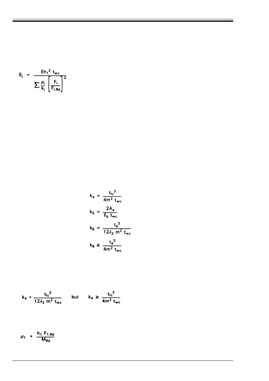
ENV 1993-1-1:1992
246
© BSI 04-2000
J.3.7 Rotational stiffness
(1) The rotational stiffness of a bolted end-plate beam-to-column connection may be approximated by:
(2) In an unstiffened connection the stiffness factors k
i
should be taken as follows:
(3) Where the column has a stiffener in the tension zone:
(4) For any other stiffened component, the relevant stiffness factor should be taken as infinity.
(5) For i = 1, 2 or 3 the modification factor È
i
should be taken as 1.
(6) For i = 4, 5 or 6 the modification factor È
i
should be obtained from:
(J.53)
where:
S
j
is the secant stiffness with respect to a particular moment M in the connection (M k M
Rd
)
M
Rd
is the design moment resistance of the connection
h
1
is the distance from the first bolt-row below the tension flange of the beam, to the centre of
resistance of the compression zone, except as noted in (8)
È
1
is the modification factor, see (5) and (6) below
k
i
is the stiffness factor for component i, see (2) to (4)
F
i
is the force in component i of the connection due to the moment M.
F
i.Rd
is the design resistance of component i of the connection
For components 2 to 6 the value of F
i
should not be taken as less than F
i.Rd
/1,5.
Column web, shear zone:
k
1
= 0,24
Column web, tension zone:
k
2
= 0,8
Column web, compressive zone:
k
3
= 0,8
Column flange, tension zone:
Bolts, tension zone:
End plate, tension zone:
but
where =
b
is the elongation length of the bolt, which may be taken as the total grip length (thickness
of material plus washers) plus half the sum of the height of the bolt head and the
height of the nut.
and
Æ
2
is as defined in Figure J.3.7.
where F
1.Rd
is the force in the first row of bolts below the tension flange of the beam, corresponding to
design moment resistance M
Rd
, except as noted in (8).
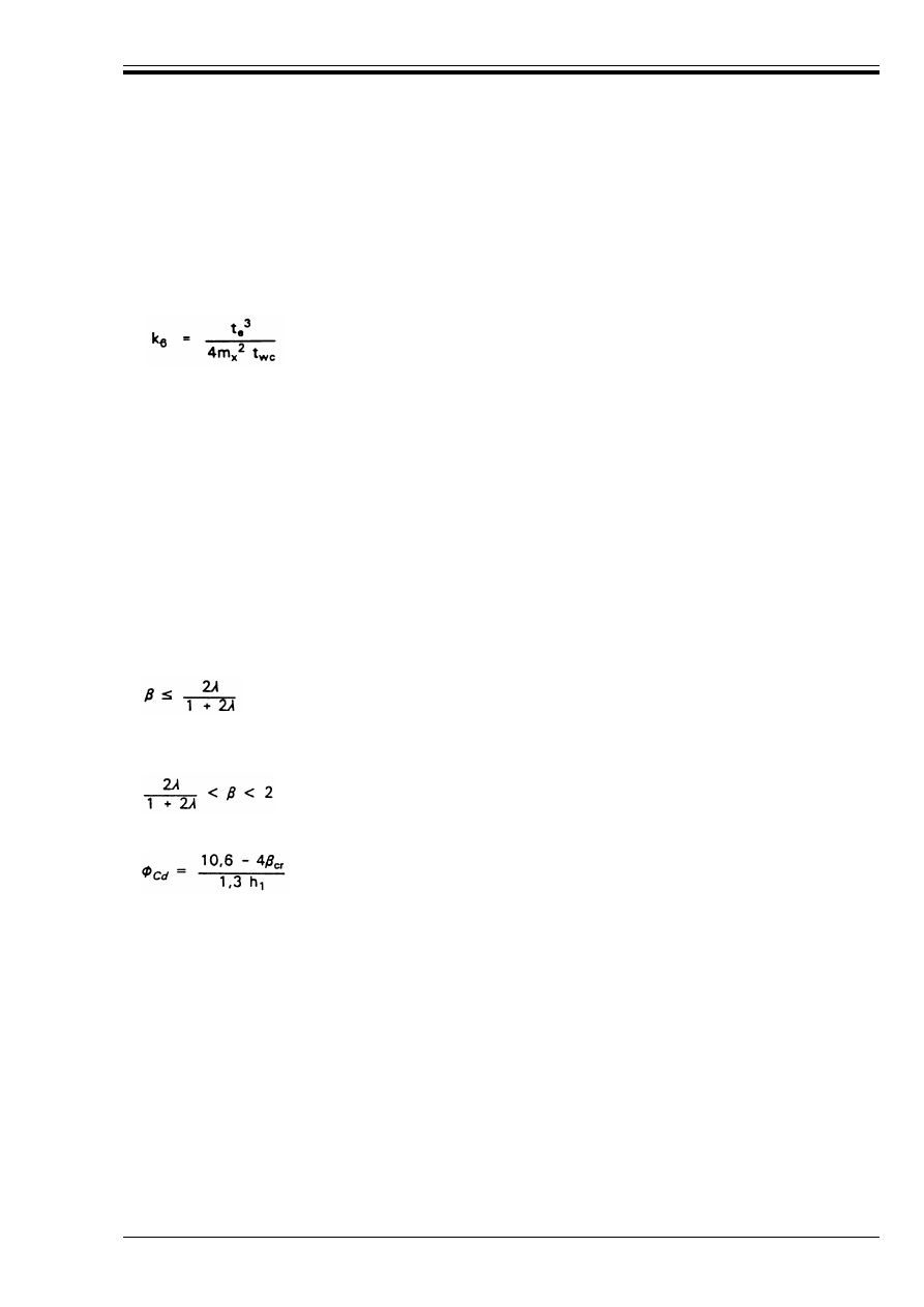
ENV 1993-1-1:1992
© BSI 04-2000
247
(7) In an extended end plate connection the rotational stiffness S
je
based on the end plate extension should
also be calculated, and the larger value S
j
or S
je
should be adopted as the rotational stiffness of the
connection.
(8) When calculating S
je
the distance h
1
should be measured from the bolt-row in the end plate extension to
the centre of resistance of the compression zone and F
1.Rd
should be taken as the force in that bolt-row
corresponding to M
Rd
. The stiffness factor k
6
should then be taken as:
where m
x
is as defined in Figure J.3.8
(9) A bolted end-plate connection may be assumed to be a rigid connection when both of the following,
conditions are satisfied:
a) The column has web stiffeners in both the tension zone and the compression zone.
b) The moment resistance is determined using Procedure J.3.2
J.3.8 Rotation capacity
(1) A bolted beam-to-column connection in which the moment resistance is governed by the resistance of the
shear zone may be assumed to have adequate rotation capacity for plastic analysis.
(2) A bolted beam-to-column connection in which the moment resistance is governed by the resistance of the
tension zone, may be assumed to have adequate rotation capacity for plastic analysis if adequate
deformation capacity is available throughout the tension zone, either in the column flange or in the beam
end-plate.
(3) The criterion given in (2) may be assumed to be satisfied if, for each bolt-row, the resistance of at least
one component (column flange or beam end-plate) is governed by Mode 1 failure, see J.3.3. This condition is
met if, for each bolt-row, whichever component gives the lower value of ¶ also satisfies the criterion:
in which ¶ and Æ are as defined in J.3.3(4).
(4) If Mode 2 failure governs, that is if the lower value of ¶ satisfies the condition:
then the rotation capacity Ì
Cd
may be obtained from:
(5) The criteria given in (2) to (4) also apply to extended end plate connections, provided that the end plate
extension has sufficient deformation capacity. This may be assumed to be satisfied if Mode 1 failure governs
in the end plate extension. In an extended end plate connection, the distance h
1
in expression (J.56) should
be measured from the bolt-row in the end plate extension to the centre of resistance of the compression zone,
but the end plate extension should be excluded in determining 
cr
.
(6) Unless the connection is classified as full-strength (as defined in 6.4.3.2) the lower value of ¶ should not
exceed 1,8.
(J.54)
(J.55)
(J.56)
where h
1
is the distance (in mm) from the first bolt-row below the tension flange of the beam to the
centre of resistance of the compression zone, except as noted in (5).
and
cr
is the value of ¶ for the component with the lower value of F
t.Rd
/CB
t.Rd
[see J.3.3(4)].
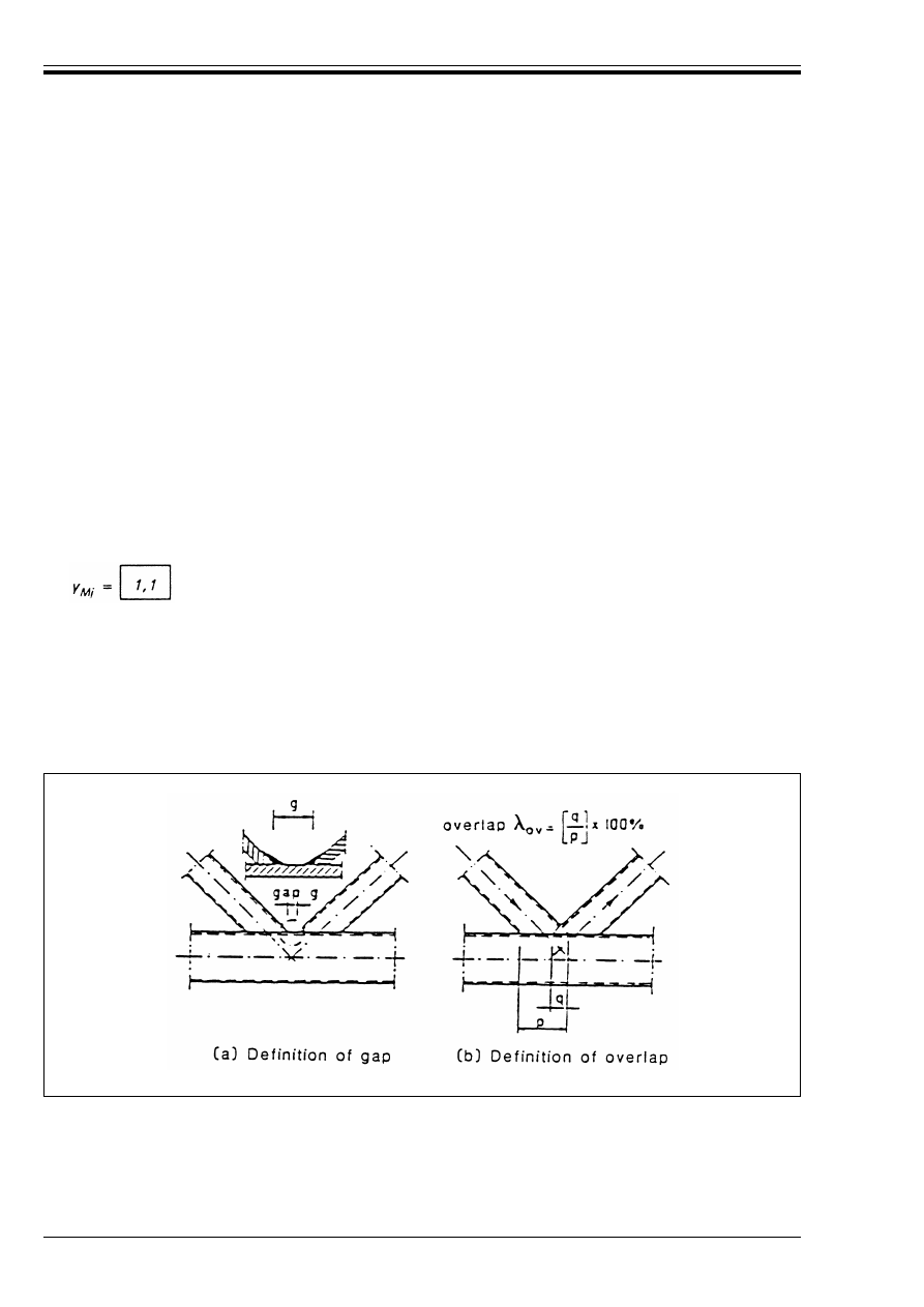
ENV 1993-1-1:1992
248
© BSI 04-2000
Annex K (normative)
Hollow section lattice girder connections
K.1 General
(1) This Annex gives detailed application rules to determine the static resistances of uniplanar joints in
lattice structures composed of rectangular, circular or square hollow sections, or combinations of these with
open sections.
(2) The static resistances of the joints are expressed in terms of maximum design axial resistances for the
brace members.
(3) These rules are valid for both hot finished hollow sections as defined in 3.2.2 and for cold formed hollow
sections as defined in 3.2.3.
(4) The nominal yield strength of hot finished hollow sections and the nominal yield strength of the basic
material of cold formed hollow sections should not exceed 355 N/mm
2
.
(5) The requirements given in 6.10.1 should be satisfied.
(6) The nominal wall thickness of hollow sections should be limited to a minimum of 2,5 mm.
(7) The nominal wall thickness of a hollow section chord should not be greater than 25 mm unless special
measures have been taken to ensure that the through thickness properties of the material will be adequate.
(8) The partial safety factor for joint resistance should be taken as:
K.2 Definitions
(1) In this Annex, a uniplanar joint in a lattice structure means a connection between members which are
situated in a single plane and which transmit primarily axial forces.
(2) The gap g is defined as the distance, measured along the length of the connecting face of the chord,
between the toes of the adjacent brace members, see Figure K.1(a).
(3) The overlap Æ
ov
is defined as (q/p) × 100 % as shown in Figure K.1(b).
(4) The symbols used in the tables in this Annex are defined in K.9.
Figure K.1 — Gap and overlap of joints
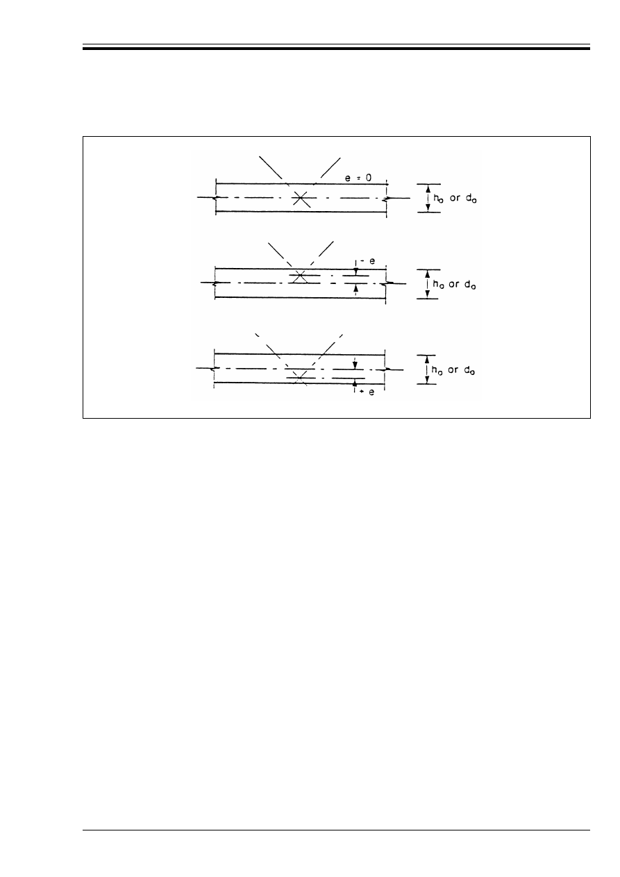
ENV 1993-1-1:1992
© BSI 04-2000
249
K.3 Field of application
(1) The application rules given in this Annex may be used only where all the following conditions are
satisfied:
a) The members should have Class 1 or Class 2 cross-sections.
b) The angles between the chords and the brace members and between adjacent brace members should not
be less than 30°.
c) Moments resulting from eccentricities may be neglected in calculating the resistance of the joint,
provided that the eccentricities are within the following limits:
(2) The members that meet at a joint should have their ends prepared in such a way that their
cross-sectional shape is not modified.
(3) In gap type joints, the gap between the brace members should not be less than (t
1
+ t
2
), to ensure that the
clearance is adequate for forming satisfactory welds.
(4) In overlap type joints, the overlap should be sufficient to ensure that the interconnection of the brace
members is adequate for satisfactory shear transfer from one brace to the other.
(5) Where overlapping brace members have different thicknesses, the thinner member should overlap the
thicker member.
(6) Where overlapping brace members are of different strength grades, the member with the lower yield
strength should overlap the member with the higher yield strength.
Figure K.2 — Eccentricity of joints
w
– 0,55 d
o
k e k 0,25 d
o
(K.1a)
w
– 0,55 h
o
k e k 0,25 h
o
(K.1b)
where e
is the eccentricity, as defined in Figure K.2
d
o
is the diameter of the chord
h
o
is the depth of the chord, in the plane of the lattice girder.
ENV 1993-1-1:1992
250
© BSI 04-2000
K.4 Analysis
(1) The axial force distribution in a lattice girder may be determined on the assumption that the members
are connected by pinned joints.
(2) Secondary moments in the joints, caused by the actual bending stiffness of the joints, may be neglected,
provided that:
• the joint geometry is within the range of validity specified in Table K.6.1, Table K.7.1 or Table K.8.1 as
appropriate, and
• the ratio of the system length to the members depth in the plane of the girder is not less than:
• 12 for chord members, and
• 24 for brace members.
(3) Eccentricities within the limits given, in section K.3 may be neglected.
(4) For fatigue assessments see Chapter 9.
K.5 Welds
(1) In welded joints, the connection should normally be established around the entire perimeter of the hollow
section by means of a butt weld, a fillet weld, or combinations of the two. However in partially overlapping
joints the hidden part of the connection need not be welded.
(2) The design resistance of the weld per unit length of the perimeter should not normally be less than the
design tension resistance of the cross-section of the member per unit length of the perimeter.
(3) The required throat thickness should be determined from 6.6.5.
(4) The criterion given in (2) will be satisfied if the throat thickness of a fillet weld satisfies the following:
• for steel to EN 10025:
• for steel to prEN 10113:
When ¾
Mj
= 1,1 and ¾
Mw
= 1,25 the value of µ is 1,0. Otherwise µ should be determined from:
(5) The criterion given in (2) may be waived where smaller weld sizes can be justified with regard both to
resistance and to deformation capacity and/or rotation capacity.
K.6 Welded joints between circular hollow sections
(1) The design values of the internal axial forces both in the brace members and in the chords at the ultimate
limit state should not exceed the design resistances of the members determined from Chapter 5.
(2) The design values of the internal axial forces in the brace members at the ultimate limit state should also
not exceed the design resistances of the joints.
(3) Provided that the geometry of the joints is within the range of validity given in Table K.6.1, the design
resistances of the joints should be determined using the formulae given in Table K.6.2.
(4) For joints outside the range of validity given in Table K.6.1 a more detailed analysis should be made.
This analysis should also take account of the secondary moments in the joints caused by the bending stiffness
of the joints.
w
for Fe 360:
a/t U 0,84µ
(K.2a)
w
for Fe 430:
a/t U 0,87µ
(K.2b)
w
for Fe 510:
a/t U 1,01µ
(K.2c)
w
for Fe E 275: a/t U 0,91µ
(K.2d)
w
for Fe E 355: a/t U 1,05µ
(K.2e)
(K.3)

ENV 1993-1-1:1992
© BSI 04-2000
251
Table K.6.1 — Range of validity for welded
joints between circular hollow sections
K.7 Welded joints between hollow section brace members and square or rectangular hollow
section chords
K.7.1 General
(1) The design values of the internal axial forces both in the brace members and in the chords at the ultimate
limit state should not exceed the design resistances of the members determined from Chapter 5.
(2) The design values of the internal axial forces in the brace members at the ultimate limit state should also
not exceed the design resistances of the joints.
K.7.2 Square or circular brace members and square chords
(1) Provided that the geometry of the joints is within the range of validity given in Table K.7.1, the design
resistances of the joints should be determined using the formulae given in Table K.7.2.
(2) For joints outside the range of validity given in Table K.7.1 refer to clause K.7.3.
0,2 k
k 1,0
5 k
k 25
5 k
k 25
5 k
k 20 for X-joints
Æ
ov
U 25 %
g U t
1
+ t
2
d
i
d
o
------
d
i
2t
i
--------
d
o
2t
o
---------
d
o
2t
o
---------
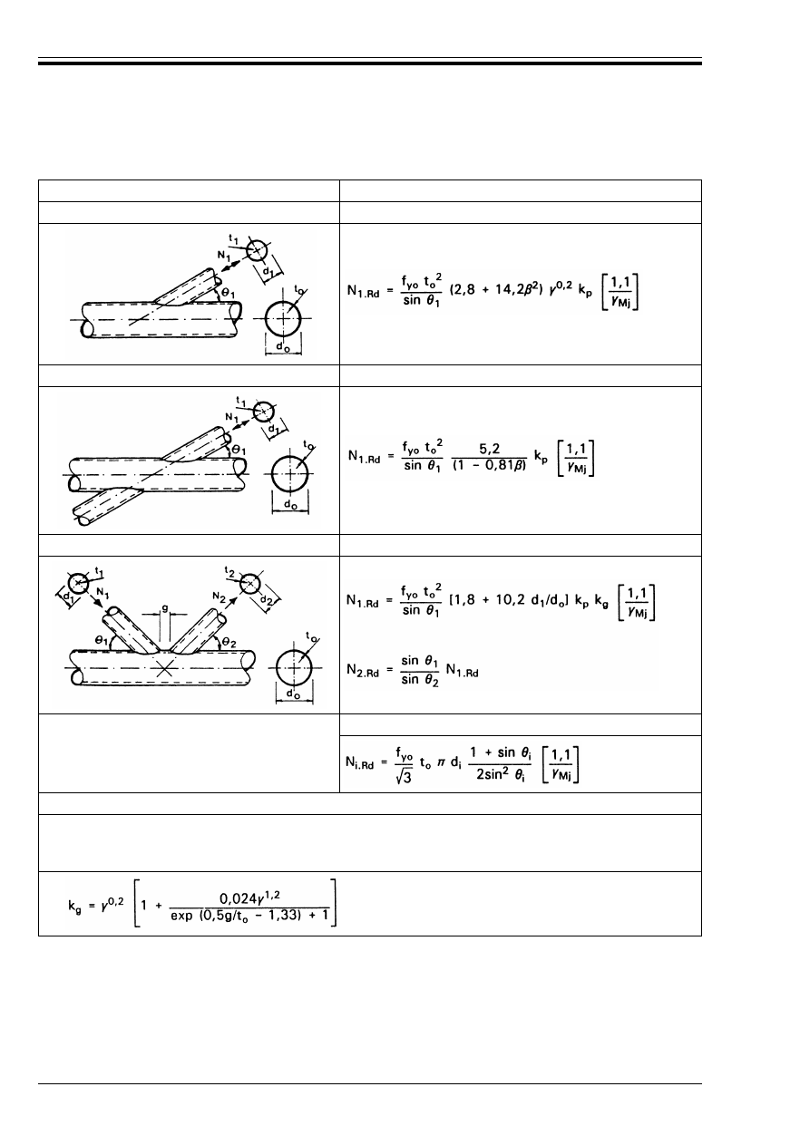
ENV 1993-1-1:1992
252
© BSI 04-2000
Table K.6.2 — Design resistances of welded joints between circular hollow sections
Type of joint
Design resistance (i = 1 or 2)
T and Y joints
Chord plastification
X joints
Chord plastification
K and N gap or overlap joints
Chord plastification
T, Y and X joints and
K, N and KT joints with a gap
When d
i
k d
o
– 2t
o
Punching shear
Functions
k
p
= 1,0
k
p
= 1 – 0,3 n
p
(1 + n
p
)
but k
p
k 1,0
for n
p
k 0 (tension)
for n
p
> 0 (compression)
(see Figure K.3)
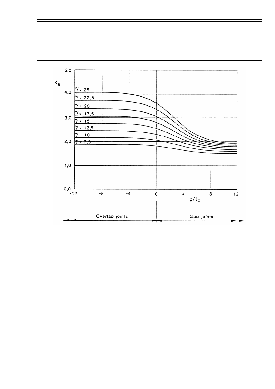
ENV 1993-1-1:1992
© BSI 04-2000
253
Figure K.3 — Values of factor k
g
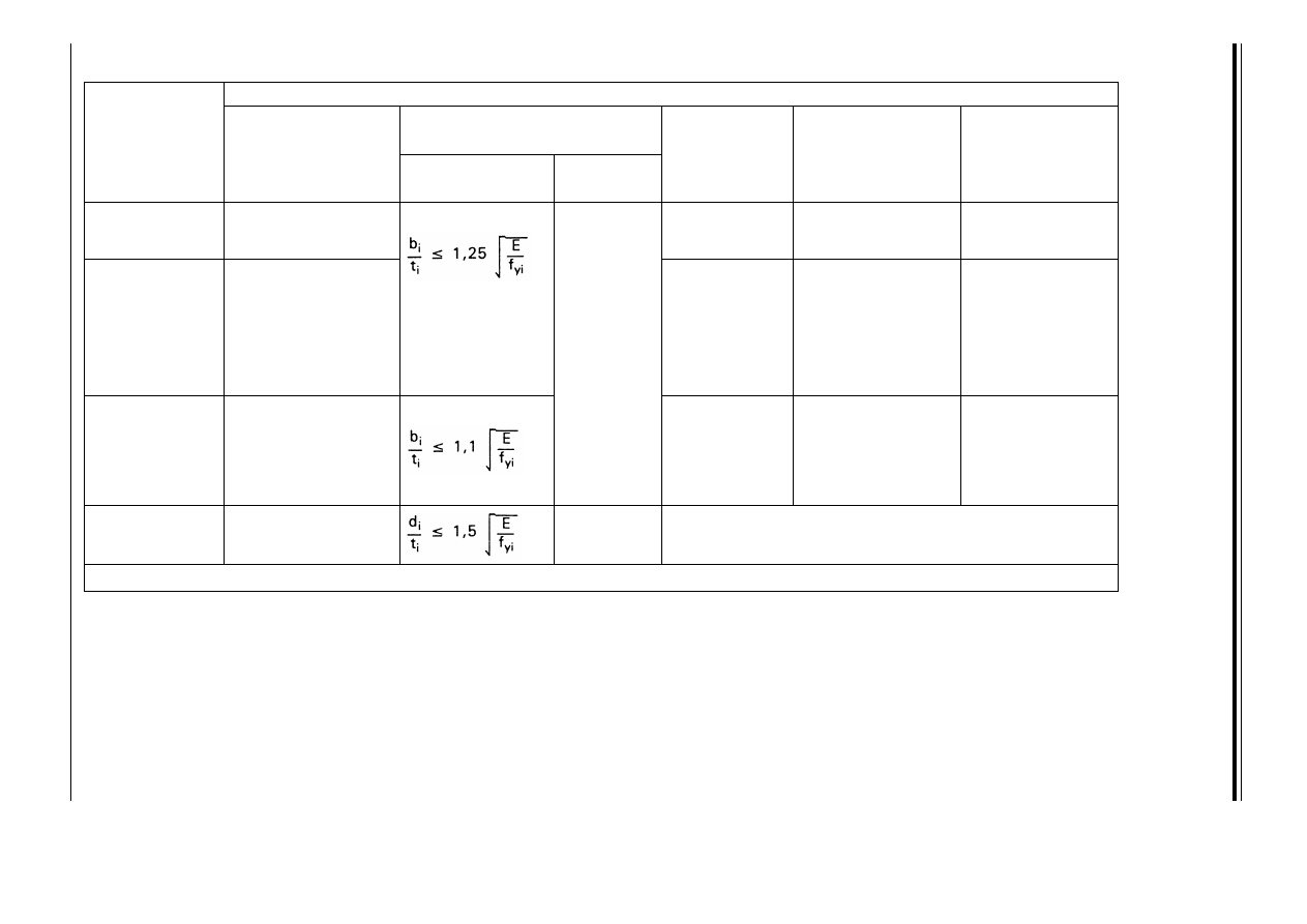
E
N
V
19
93
-1
-1
:1
99
2
25
4
©
B
S
I 0
4-
20
00
Table K.7.1 — Range of validity for welded joints between square or circular hollow section brace members and
square hollow section chords
a
Type of joint
Joint parameters [i = 1 or 2, j = overlapped brace]
Gap or Overlap
Compression
Tension
T, Y or X joint
0,25 k
k 0,85
k 35
10 k
k 35
K gap joint
N gap joint
U 0,1 + 0,01
and
U 0,35
U 0,5(1 – ¶)
and
k 35
15 k
k 35
0,6 k
k 1,3
but
k 0,5(1 – ¶)
and g U t
1
+ t
2
K overlap joint
N overlap joint
U 0,25
k 40
k 1,0
U 0,75
25 % k Æ
ov
k 100 %
Circular brace
member
0,4 k
k 0,8
k 50
As above but with d
i
replacing b
i
a
NOTE Outside these parameter ranges the resistance of the joint may be determined as for a joint with a rectangular chord section, see clause K.7.3
.
b
i
b
o
----- or
d
i
b
o
-----
b
i
t
i
---- or
d
i
t
i
-----
b
o
t
o
-----
b
1
b
2
+
2 b
1
------------------ or
b
i
b
j
---- and
t
i
t
j
---
b
i
b
o
-----
b
i
t
i
-----
b
o
t
o
------
b
i
b
o
-----
b
o
t
o
------
b
i
b
o
-----
g
b
o
-----
b
i
t
i
-----
b
o
t
o
------
b
1
b
2
+
2b
1
-------------------
g
b
o
-----
b
i
b
o
-----
b
o
t
o
------
t
i
t
j
----
b
i
b
j
-----
d
i
b
o
-----
d
i
t
i
-----
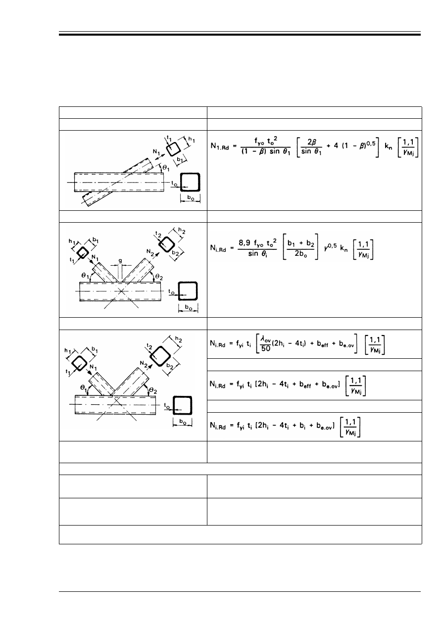
ENV 1993-1-1:1992
© BSI 04-2000
255
Table K.7.2 — Design resistances of welded joints square or circular hollow section
brace members and square hollow sections chords
Type of joint
Design resistance (i = 1 or 2, j = overlapped brace)
T, Y and X joints
Chord face yielding
k 0,85
K and N gap joints
Chord face yielding
k 1,0
K and N overlap joints
a
Effective width
25 % k Æ
ov
< 50 %
Effective width
50 % k Æ
ov
k 80 %
Effective width
Æ
ov
U 80 %
Circular braces
Multiply the above resistances by Ï/4. Replace b
1
and h
1
by d
1
and replace b
2
and h
2
by d
2
.
Functions
for n k 0 (tension): k
n
= 1,0
for n U 0 (compression): k
n
= 1,3 –
but k
n
k 1,0
but b
eff
k b
i
but b
e.ov
k b
i
a
Only the overlapping brace need be checked. The brace member efficiency (ie. the design resistance of the joint divided by the
design plastic resistance of the brace) for the overlapped brace should be taken as not more than that of the overlapping brace.
0,4n
------------
b
eff
10
b
o
/t
o
-------------
f
yo
t
o
f
yi
t
i
--------------
b
i
=
b
e.ov
10
b
j
/t
j
-----------
f
yj
t
j
f
yi
t
i
------------ b
i
=

ENV 1993-1-1:1992
256
© BSI 04-2000
K.7.3 Rectangular sections
(1) The design resistances of joints between rectangular hollow sections, and of joints between square hollow
sections outside the range of validity of Table K.7.1, should be based on the following criteria as applicable:
a) Plastic failure of the chord face or the chord cross section.
b) Crack initiation leading to rupture of the bracings from the chord (punching shear).
c) Cracking in the welds or in the bracings (effective width).
d) Chord wall bearing or local buckling under the compression bracing.
e) Local buckling in the compressive areas of the members.
f) Shear failure of the chord.
(2) Figure K.4(a) to (f) illustrates the modes of failure relevant to criteria a) to f) given in (1).
K.8 Welded joints between hollow section brace members and an I or H section chord
(1) The design values of the internal axial forces both in the brace members and in the chords at the ultimate
limit state should not exceed the design resistances of the members determined from Chapter 5.
(2) In gap-type joints, the design resistances of the chords allowing for the shear force transferred between
the brace members by the chords should be determined from 5.4.9, neglecting the associated secondary
moments, as follows:
(3) The design values of the internal axial forces in the brace members at the ultimate limit state should also
not exceed the design resistances of the joints.
(4) Provided that the geometry of the joints is within the range of validity given in Table K.8.1, the design
resistances of the joints should be determined using the formulae given in Table K.8.2.
(5) For joints outside the range of validity given in Table K.8.1 a more detailed analysis should be made.
This analysis should also take account of the secondary moments in the joints caused by the bending stiffness
of the joints.
w
when V
Sd
/V
p
=
.Rd
k 0,5: N
o.Rd
= f
yo
A
o
/¾
M0
(K.4)
w
when V
Sd
/V
p
=
.Rd
> 0,5 but V
Sd
/V
p
=
.Rd
k 1,0:
N
o.Rd
= f
yo
[A
o
– A
v
(2V
Sd
/V
p
=
.Rd
– 1)
2
]/¾
M0
(K.5)
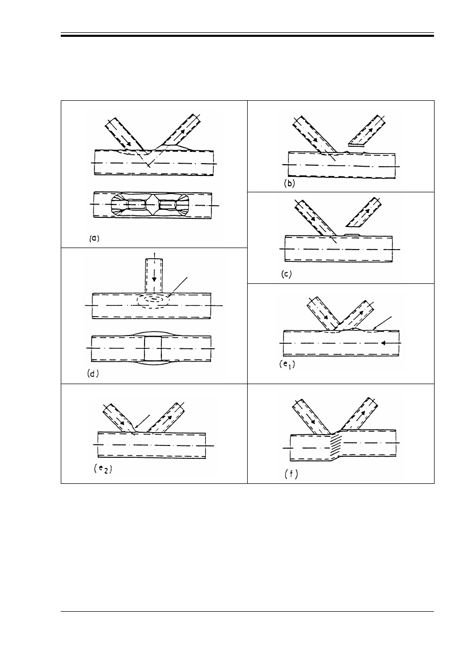
ENV 1993-1-1:1992
© BSI 04-2000
257
Figure K.4 — Modes of failure — rectangular sections
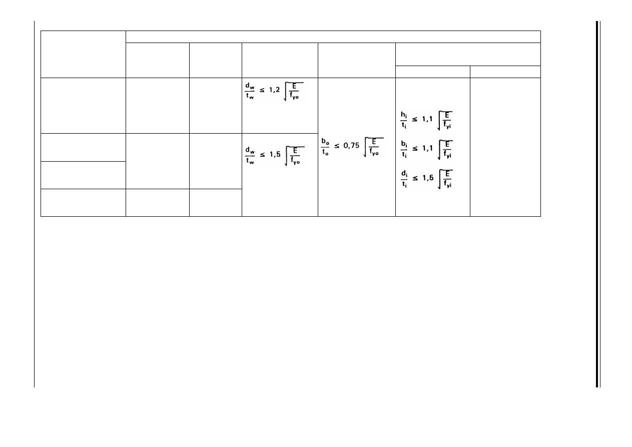
E
N
V
19
93
-1
-1
:1
99
2
25
8
©
B
S
I 0
4-
20
00
Table K.8.1 — Range of validity for welded joints between hollow section brace members and I or H section chords
Type of joint
Joint parameter [i = 1 or 2, j = overlapped brace]
Compression
Tension
X-joint
0,5 k
k 2,0
and
d
w
k 400 mm
k 35
T-joint
Y-joint
and
d
w
k 400 mm
k 35
K — gap joint
N — gap joint
k 50
K — overlap joint
N — overlap joint
0,5 k
k 2,0
U 0,75
h
i
b
i
----
b
j
b
i
----
d
w
t
w
------
b
o
t
o
-----
b
i
t
i
----,
h
i
t
i
-----,
d
i
t
i
-----
h
i
b
i
-----
h
i
t
i
-----
h
i
b
i
-----
1,0
=
b
i
t
i
-----
d
i
t
i
-----
h
i
b
i
-----
b
j
b
i
-----
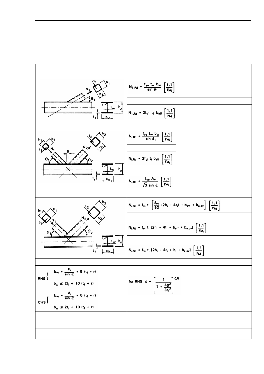
ENV 1993-1-1:1992
© BSI 04-2000
259
Table K.8.2 — Design resistances of welded joints between hollow section brace
members and I or H section chords
Type of joint
Design resistance (i = 1 or 2, j = overlapped brace)
T, Y and X joints
Chord web yielding
Effective width
K and N gap joints
Chord web stability
No effective width check required if:
g/t
f
U 20 – 28
k 1,0 – 0,03¾ and
0,75 k d
1
/d
2
k 1,33 for CHS
0,75 k b
1
/b
2
k 1,33 for RHS
Effective width
Chord shear
K and N overlap joints
a
Effective width
25 % k Æ
ov
< 50 %
Effective width
50 % k Æ
ov
< 80 %
Effective width
Æ
ov
U 80 %
Functions
A
v
= A
o
– (2 – µ)b
o
t
f
+ (t
w
+ 2r)t
f
for CHS brace µ = 0
b
eff
= t
w
+ 2r + 7
t
f
but b
eff
k b
i
but b
e.ov
k b
i
a
Only the overlapping brace need be checked. The brace member efficiency (i.e. the design resistance of the joint divided by the
design plastic resistance of the brace) for the overlapped brace should be taken as not more than that of the overlapping brace.
f
yo
f
yi
-------
b
e.ov
10
b
j
/t
j
-----------
f
yj
t
j
f
yi
t
i
------------ b
i
=
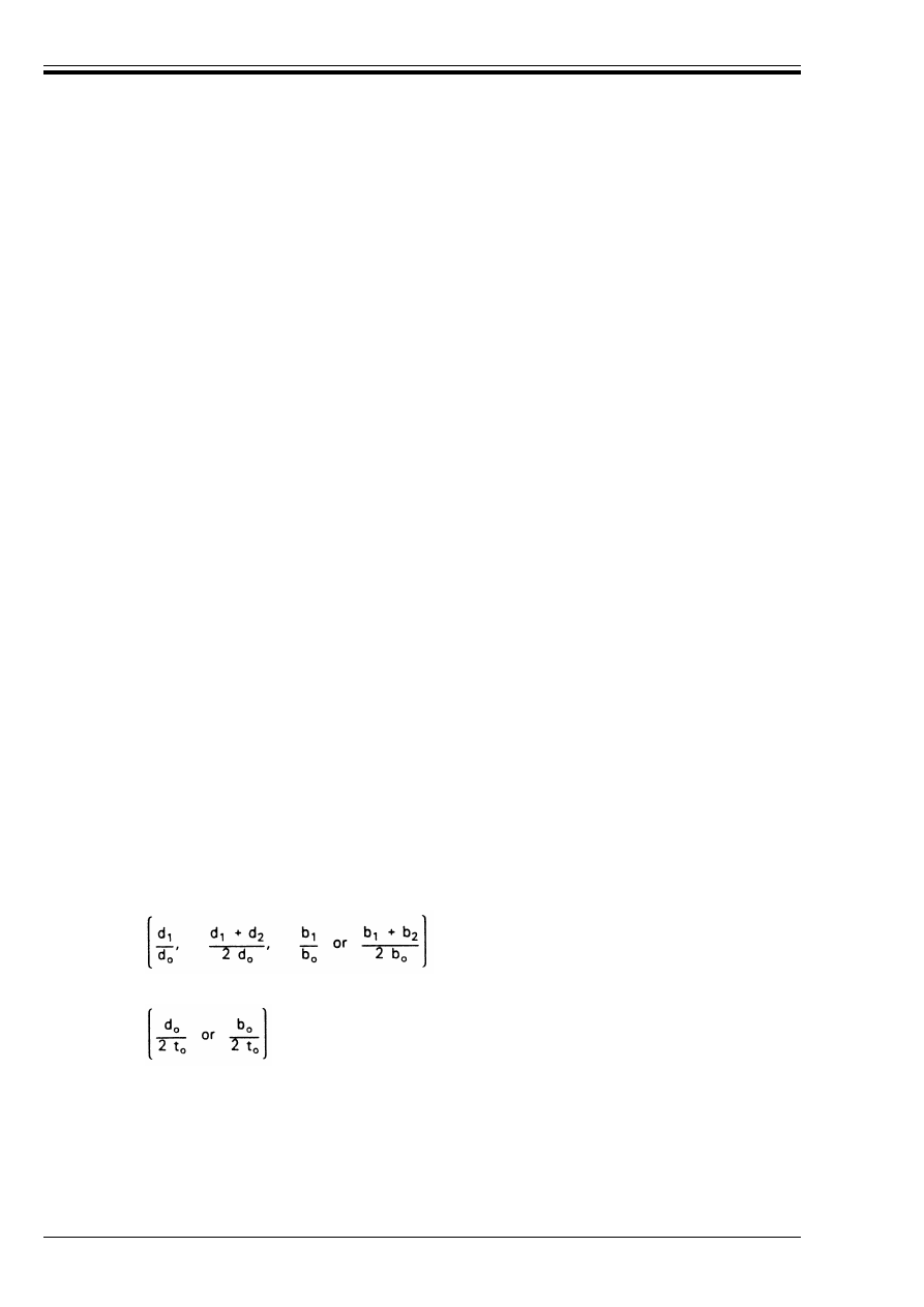
ENV 1993-1-1:1992
260
© BSI 04-2000
K.9 Symbols used in tables
A
i
is the cross-sectional area of member i
A
v
is the shear area of the chord
E
is the elastic modulus of steel
N
i
is the axial force in member i
N
i.Rd
is the design resistance of the joint for the axial force in member i
a
is the throat thickness of a fillet weld
b
i
is the external width of a square or rectangular hollow section member i (i = 0, 1 or 2)
b
eff
is the effective width for a brace to chord connection
b
e.ov
is the effective width for an overlapping brace to overlapped brace connection
b
w
is the effective width for the web of the chord
d
i
is the diameter of a circular hollow section member i (i = 0, 1 or 2)
d
w
is the depth of the web of an I or H section chord
e
is the eccentricity of a joint
f
yi
is the design value of the yield strength of member i (i = 0, 1 or 2)
g
is the gap between the braces of a K or N joint
h
i
is the external depth of a section, member i (i = 0, 1 or 2)
i
is the integer subscript used to designate a member of a joint, i = 0 denoting a chord and i = 1
and 2 the brace members. In joints with two braces, i = 1 normally denotes the compression
brace and i = 2 the tension brace
i, j
are integer subscripts used to denote respectively the overlapping brace member and the
overlapped brace member.
k
g
, k
p
are factors defined in Table K.6.2
k
n
is a factor defined in Table K.7.2
n
=
Ö
o
/f
yo
n
p
=
Ö
p
/f
yo
r
o
is the root radius of an I or H section chord
t
i
is the wall thickness of member i (i = 0, 1 or 2)
t
f
is the flange thickness of an I or H section
t
w
is the web thickness of an I or H section
µ
is the factor giving the effectiveness of the chord flange for shear
is the mean brace to chord diameter or width ratio
¾
is the ratio of the chord width or diameter to twice its wall thickness
G
i
is the included angle between the chord and a brace member i (i = 1 or 2)
Æ
ov
is the overlap ratio, expressed as a percentage (Æ
ov
= (q/p) × 100 %)
Ö
o
is the maximum compressive stress in the chord at the joint, due to axial force and bending
moment
Ö
p
is the value of Ö
o
excluding the stress due to the horizontal components of the forces in the
braces at that joint
CHS
is used as an abbreviation for “circular hollow section”
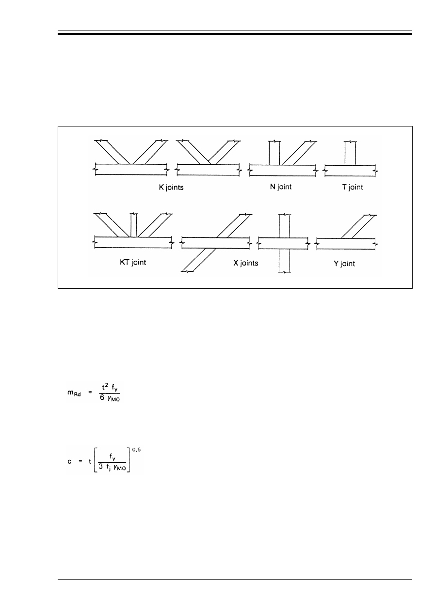
ENV 1993-1-1:1992
© BSI 04-2000
261
Annex L (normative)
Design of column bases
L.1 Base plates
(1) Columns should be provided with adequate steel base plates to distribute the compression forces in
compressed parts of the column over a bearing area, such that the bearing pressure does not exceed the
design strength f
j
of the joint (grout and concrete).
(2) The resistance moment m
Rd
per unit length of a yield line in the base plate, either in the compression
region or in the tension region, should be taken as:
(3) The forces transferred to the foundation from the compression elements of the column should be assumed
to be spread uniformly by the base plate as shown in Figure L.1(a). The pressure on the resulting bearing
area should not exceed the bearing strength f
j
of the joint and the additional bearing width c should not
exceed:
(4) Where the projection of the base plate is less than c the effective bearing area should be assumed to be as
indicated in Figure L.1(b).
(5) Where the projection of the base plate exceeds c the additional projection should be neglected,
see Figure L.1(c).
RHS
is used as an abbreviation for “rectangular hollow section”, which in this context also includes
a square hollow section.
K, N, T, X, Y and KT joints are abbreviated descriptions for the types of joints shown in Figure K.5.
Figure K.5 — Types of joints
(L.1)
(L.2)
where
t
is the thickness of the steel base plate
and
f
y
is the yield strength of the steel base plate material
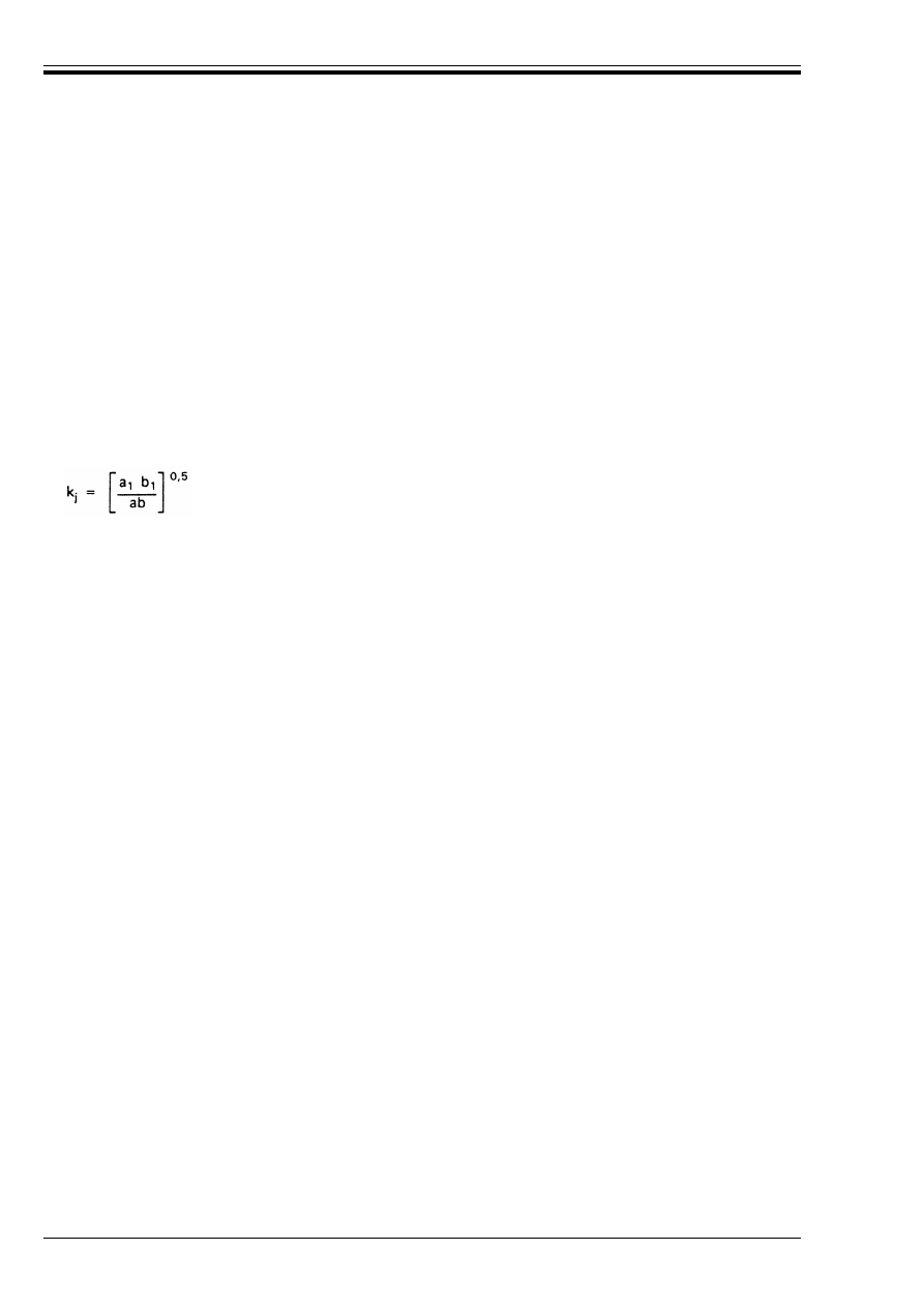
ENV 1993-1-1:1992
262
© BSI 04-2000
(6) The bearing strength of the joint f
j
should be determined from:
(7) The concentration factor k
j
may be taken as 1,0 or otherwise as:
(8) For a
1
the least of the following should be taken:
(9) For b
1
the least of the following should be taken:
(10) When the column base is placed on a concrete slab, due account should be taken of the moment
resistance and the punching resistance of the concrete slab.
f
j
= 
j
k
j
f
cd
(L.3)
where:
j
is the joint coefficient, which may be taken as 2/3 provided that the characteristic
strength of the grout is not less than 0,2 times the characteristic strength of the
concrete foundation and the thickness of the grout is not greater than 0,2 times the
smallest width of the steel base plate
k
i
is the concentration factor
f
cd
is the design value of the concrete cylinder compressive strength of the concrete given by:
f
cd
= f
ck
/¾
c
in which f
ck
is the characteristic cylinder compressive strength of the concrete determined in
conformity with ENV 1992-1-1 Eurocode 2-1.1
and
¾
c
is the partial safety factor for concrete material properties given in Eurocode 2-1.1.
(L.4)
where
a and b
are the dimensions of the base plate
and
a
1
and b
1
are the dimensions of the effective area, as indicated in Figure L.2.
w
a
1
= a + 2 a
r
(L.5a)
w
a
1
= 5 a
(L.5b)
w
a
1
= a + h
(L.5c)
w
a
1
= 5 b
1
but a
1
3 a
(L.5d)
w
b
1
= b + 2 b
r
(L.6a)
w
b
1
= 5 b
(L.6b)
w
b
1
= b + h
(L.6c)
w
b
1
= 5 a
1
but b
1
U b
(L.6d)
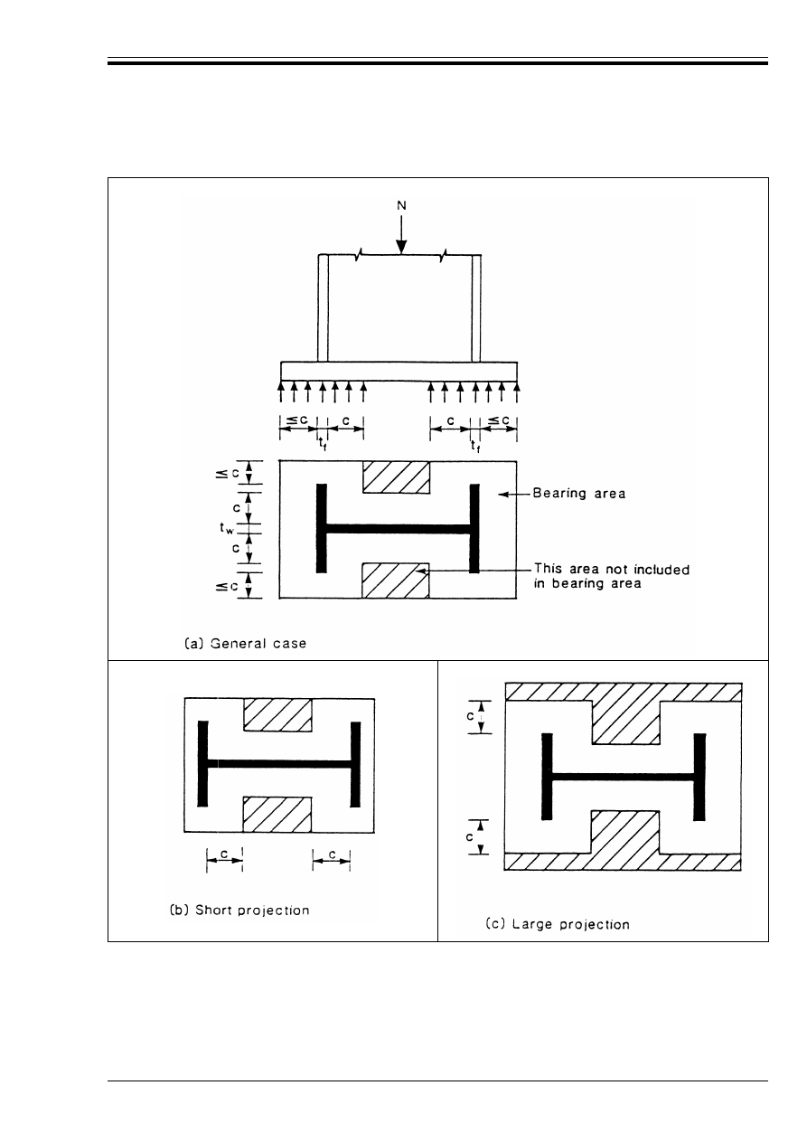
ENV 1993-1-1:1992
© BSI 04-2000
263
Figure L.1 — Area in compression under base plate
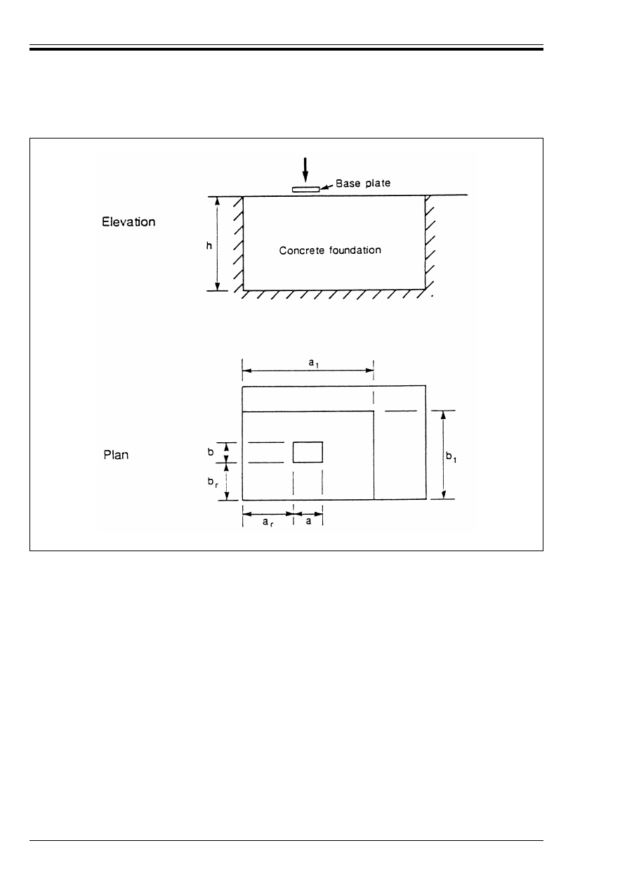
ENV 1993-1-1:1992
264
© BSI 04-2000
L.2 Holding down bolts
(1) Holding down bolts should be designed to resist the effects of the design loads. They should provide
resistance to tension due to uplift forces and bending moments where appropriate.
(2) If no special elements for resisting shear are provided, such as block or bar shear connectors, it should be
demonstrated that either the shear resistance of the holding down bolts or the friction resistance of the base
plate is sufficient to transfer the design shear force.
(3) When calculating the tension forces in the holding down bolts due to bending moments, the lever arm
should not be taken as more than the distance between the centroid of the bearing area on the compression
side and the centroid of the bolt group, taking the tolerances on the positions of the holding down bolts into
account.
(4) The design resistance of the holding down bolts should be determined from 6.5.5.
(5) Holding down bolts should either be anchored into the foundation by:
• a hook [Figure L.3(a)], or
• a washer plate [Figure L.3(b)], or
• some other appropriate load distributing member embedded in the concrete, or
• some other fixing which has been adequately tested and approved by the designer, the client and the
competent authority.
(6) The anchorage of holding down bolts should be in accordance with the relevant clauses in
ENV 1992-1-1 Eurocode 2-1.1.
Figure L.2 — Column base
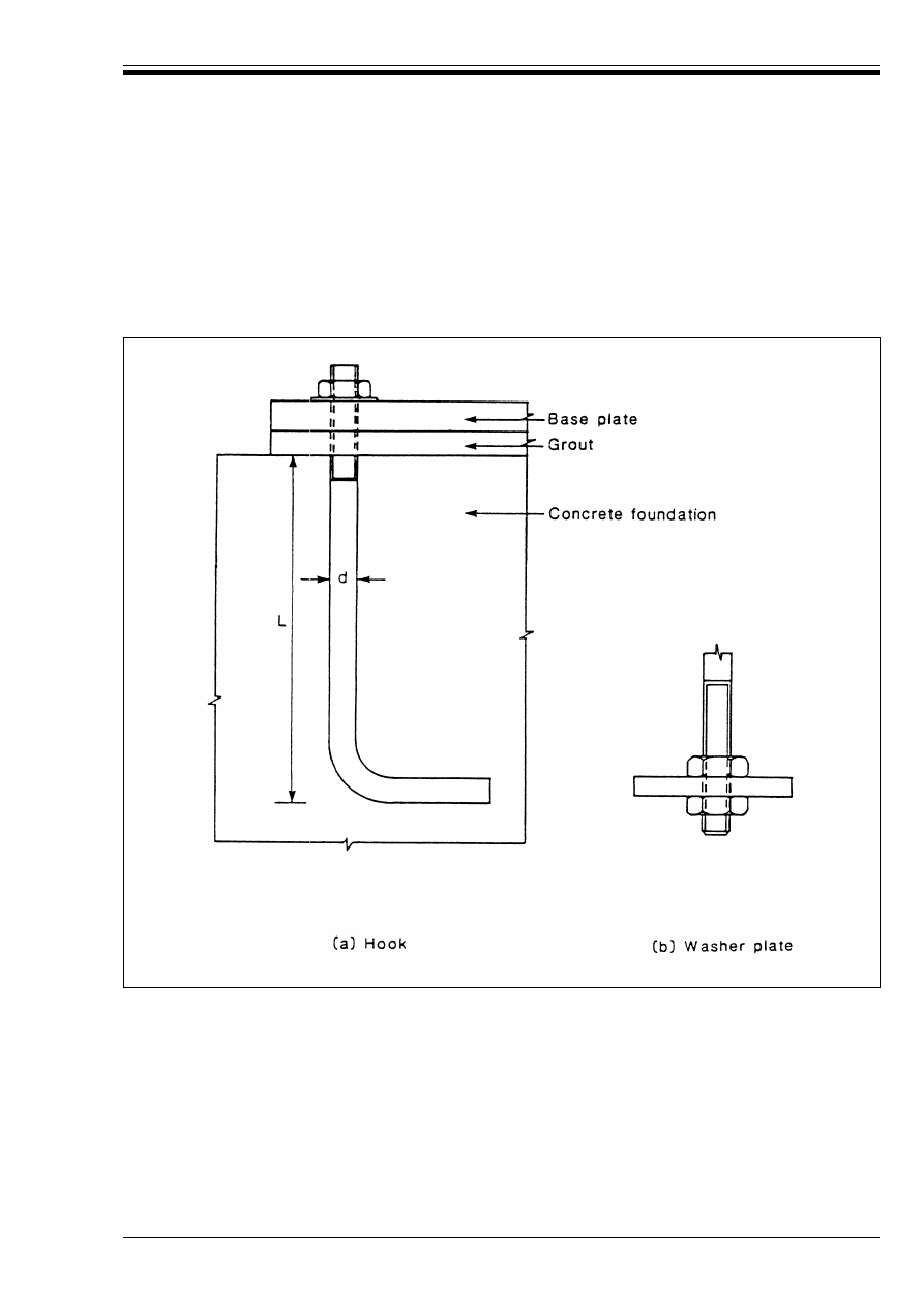
ENV 1993-1-1:1992
© BSI 04-2000
265
(7) When the bolts are provided with a hook, the anchorage length should be such as to prevent bond failure
before yielding of the bolt. The anchorage length should be calculated in accordance with the relevant clauses
in Eurocode 2. This type of anchorage should not be used for bolts with a specified yield strength higher
than 300 N/mm
2
.
(8) When the holding down bolts are provided with a washer plate or other load distributing member, no
account should be taken of the contribution of bond. The whole of the force should be transferred through the
load distributing device.
Annex M (normative)
Alternative method for fillet welds
(1) The resistance of a fillet weld may be verified by the following method as an alternative to the method
given in 6.6.5.3.
(2) In this method, the forces transmitted by a unit length of weld are resolved into components parallel and
transverse to the longitudinal axis of the weld and normal and transverse to the plane of its throat.
(3) A uniform distribution of stress is assumed on the throat section of the weld, leading to the normal
stresses and shear stresses shown in Figure M.1, as follows:
Figure L.3 — Anchorage of holding down bolts
Ö
8
is the normal stress perpendicular to the throat
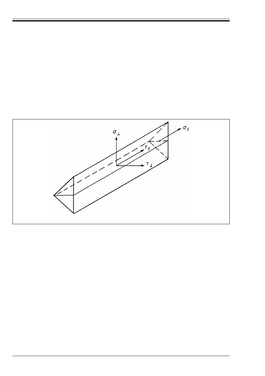
ENV 1993-1-1:1992
266
© BSI 04-2000
(4) The normal stress Ö
parallel to the axis is not considered when verifying the resistance of the weld.
(5) The resistance of the fillet weld will be sufficient if the following are both satisfied:
Annex Y (informative)
Guidelines for loading tests
Y.1 General
(1) Testing may be undertaken when:
a) the calculation models specified in Chapters 4 to 6 are not sufficient for a particular structure or
structural component or may lead to uneconomic results [see tests (1) and (2) below];
b) the design resistance of a component or structure is to be established from a knowledge of its ultimate
resistance [see test (3) below];
c) confirmation is required of the consistency of production of components or structures originally
justified by testing [see test (4) below];
d) The actual performance of an existing structure is to be established because its resistance is in
question [see test (1) below].
(2) To meet these situations a basis is presented for four types of tests:
i)
an acceptance test for confirmation of general structural behaviour (see Y.4.1);
ii) a strength test against the required ultimate loads (see Y.4.2);
iii) a test to failure, to determine the ultimate resistance and mode of failure (see Y.4.3);
iv) a check test to establish consistency of production (see Y.4.4).
(3) These test procedures are intended for steel structures only.
Ö
is the normal stress parallel to the axis of the weld
Ù
8
is the shear stress (in the plane of the throat) perpendicular to the axis of the weld
Ù
is the shear stress (in the plane of the throat) parallel to the axis of the weld.
[Ö
8
2
+ 3 (Ù
8
2
+ Ù
2
)]
0,5
k f
u
/(
w
¾
Mw
)
(M1)
and
Ö
8
k f
u
/¾
Mw
where f
u
and 
w
are as defined in 6.6.5.3.
Figure M.1 — Stresses on the throat section of a fillet weld

ENV 1993-1-1:1992
© BSI 04-2000
267
(4) For cold-formed steel sheeting and members standard testing procedures have been developed which are
specified in ENV 1993-1-3 Eurocode 3-1.3
27)
.
(5) For structures of composite construction in steel and concrete reference should be made to
ENV 1994-1-1 Eurocode 4-1.1
27)
.
(6) Testing of scale models or of items subject to fluctuating loads which could cause fatigue to become a
design criterion is not covered by this Annex.
Y.2 Test conditions
(1) The design of the test rig shall be such that the loading system adequately simulates the magnitude and
distribution of the loading and allows the specimen to perform in a manner representative of service
conditions.
(2) The specimen should be free to deflect under load. Lateral and torsional restraints should be
representative of those in service.
(3) Care shall be taken to avoid inadvertent eccentricities at the points of application of the test loads and
at the supports.
(4) Load and deflection measurements shall be controlled as closely as practicable. The loading system shall
be able to follow the movements of the specimen without interruption or abnormal restraint.
(5) Deflections should be measured at sufficient points of high movement to ensure that the maximum value
is determined. The anticipated magnitude of such deflections should be estimated in advance. Generous
allowances should be made for movement beyond the elastic range.
(6) In some situations it may be desirable to determine the magnitude of stresses in a specimen. This may be
demonstrated qualitatively by means of brittle coatings or quantitatively by measurements of strain. Such
information should be considered supplementary to the overall behaviour as determined by deflections.
Y.3 General test procedures
(1) Where the self weight of the specimen is not representative of the actual permanent load in service,
allowance for the difference shall be made in the calculation of the test loads to be applied.
(2) Prior to any test, preliminary loading (not exceeding the characteristic values of the relevant loads) may
be applied and then removed, in order to bed down the test specimen onto the test rig.
(3) Loading shall be applied in a number of regular increments (not less than 5) at regular intervals in each
phase. Sufficient time shall be allowed between each increment for the specimens to reach stationary
equilibrium. After each increment the specimen shall be carefully examined for signs of rupture, yield or
buckling.
(4) A running plot should be maintained of loading against the principal deflection. When this indicates
significant non-linearity, then the load increments should be reduced.
(5) On the attainment of maximum load for either acceptance or strength tests, this load shall be
maintained at a constant value for at least 1 hour. Readings of load and deflection shall be taken at
intervals of 15 minutes and the loading shall be maintained constant until there is no significant increase
in deflection during a 15 minute period and at least 1 hour has elapsed.
(6) Unloading shall be completed in regular decrements, with deflection readings taken at each stage and
again when the unloading is complete.
(7) Where test results are used to establish or confirm the behaviour of similar structures or components
the properties of the steel used in the relevant items shall be established by coupon tests to validate
comparisons between tests carried out on different specimens or at different times.
(8) Coupons should either be cut from the same sections or plates or else recovered from unyielded areas of
the specimen after test.
Y.4 Specific test procedures
Y.4.1 Acceptance test
(1) This test is intended as a non-destructive test for confirming structural performance. For acceptance,
the assembly shall prove capable of sustaining the test loading given in (3).
(2) It should be recognised that such loading applied to certain structures may cause permanent local
distortions. Such effects do not necessarily indicate structural failure in an acceptance test, but the
possibility of their occurrence should be agreed before testing.
27)
In preparation

ENV 1993-1-1:1992
268
© BSI 04-2000
(3) The test load for an acceptance test should be:
(4) The assembly shall satisfy the following criteria:
a) it shall demonstrate substantially linear behaviour under test loading
b) on removal of the test load the residual deflection should not exceed 20 % of the maximum recorded.
(5) If the conditions given in (4) are not satisfied the test may be repeated once only. The assembly shall
demonstrate substantially linear behaviour under this second application of the test loading and the new
residual deflection shall not exceed 10 % of the maximum recorded during the second test.
Y.4.2 Strength test
(1) The strength test is used to confirm the calculated resistance of a structure or component.
(2) Where a number of items are to be constructed to a common design, and one or more prototypes are
tested to confirm their strength, the others may be accepted without further tests provided they are similar
in all relevant respects to the prototype, see Y.4.4.
(3) Before carrying out the strength test the specimen should first be submitted to and satisfy the acceptance
test described in Y.4.1.
(4) The test load for a strength test shall be based on the calculated design load for the ultimate limit state
as given in Chapter 2 for the appropriate combination of permanent and variable loads.
(5) The resistance of the assembly under test will be dependent on the material properties. The actual yield
strengths of all the steel materials in the assembly shall be determined from coupon tests.
(6) The value of the averaged yield strength f
ym
taken from such tests shall be determined with due regard
to the importance of each element in the assembly.
(7) The test load F
test.s
(including self weight) shall be determined from:
(8) At this load there shall be no failure by buckling or rupture of any part of the specimen.
(9) On removal of the test load the deflection shall reduce by at least 20 %.
Y.4.3 Test to failure
(1) The objective of a test to failure is to determine the design resistance from the actual ultimate
resistance.
(2) It is only from a test to failure that the actual mode of failure and resistance of an specimen can be
determined. Where the specimen is not required for use it may be advantageous to secure this additional
information after a strength test.
(3) In this situation it is still desirable to carry out the load cycling of the acceptance and strength tests. An
estimate should be made of the anticipated ultimate resistance as a basis for such tests.
(4) Before a test to failure, the specimen should first satisfy the strength test described in Y.4.2. Where the
ultimate resistance has been estimated its value should be reviewed in the light of the specimen’s behaviour
in the strength test.
(5) During a test to failure the loading shall first be applied in increments up to the strength test load, as
specified in Y.4.2. Subsequent load increments shall then be determined from consideration of the principal
plot.
(6) The test load resistance F
test.R
shall be determined as that load at which the specimen is unable to
sustain any further increases in load.
(7) At this load, gross permanent distortion is likely to have occurred and in some cases gross deformation
may define the test limit.
w
× (actual self-weight present during test),
w
× (remainder of the permanent load) and
w
× (variable loads)
F
test.s
= ¾
M1
F
Sd.ult
(f
ym
/f
y
)
(Y.1)
where F
Sd.ult
is the design load for the ultimate limit state.

ENV 1993-1-1:1992
© BSI 04-2000
269
(8) Not less than three tests shall be carried out on nominally identical specimens.
(9) If the deviation of any individual test result from the mean value obtained from all the tests
exceeds 10 %, at least six tests shall be carried out. The determination of the design resistance F
Rd
shall
then be carried out in accordance with the statistical method given in Annex Z
28)
.
(10) When the deviation from the mean does not exceed 10 %, the design resistance may be determined
from (11) to (14).
(11) Provided that there is a ductile failure, the design resistance F
Rd
may be determined from:
(12) In the case of a sudden (“brittle”) rupture type failure the design resistance may be determined from:
(13) In the case of a sudden (“brittle”) buckling type failure the design resistance shall be determined from:
(14) In the case of a ductile buckling type failure in which the relevant slenderness Æ can be reliably
assessed, the design resistance may [as an alternative to (11)] be determined from:
Y.4.4 Check tests
(1) Where a component or assembly is designed on the basis of strength tests or tests to failure as described
in Y.4.2 and Y.4.3 and a production run is carried out of such items, an appropriate number of samples (not
less than two) shall be selected from each production batch at random.
(2) The samples should be carefully examined to ensure they are similar in all respects to the prototype
tested, particular attention being given to the following:
a) dimensions of components and connections;
b) tolerance and workmanship
c) quality of steel used, checked with reference to mill certificates.
(3) Where it is not possible to determine either the variations or the effect of variations from the prototype,
an acceptance test shall be carried out as a check test.
(4) In this check test, the deflections shall be measured at the same positions as in the acceptance test of
the prototype. The maximum measured deflection shall not exceed 120 % of the deflection recorded during
the acceptance test on the prototype and the residual deflection should not be more than 105 % of that
recorded for the prototype.
Y.4.5 Testing to determine strength functions and model factors
(1) Strength functions and model factors may be evaluated from the results of appropriate series of tests to
failure.
(2) The determination of the design value for the strength shall be in accordance with the evaluation
procedure given in Annex Z
28)
.
28)
In preparation
F
Rd
= 0,9F
test.R.min
(f
y
/f
ym
)/¾
M1
(Y.2)
where F
test.R.min
is the minimum test result
and
f
ym
is the averaged yield strength, see Y.4.2(6).
F
Rd
= 0,9F
test.R.min
(f
y
/f
um
)/¾
M1
(Y.3)
where f
um
is the averaged ultimate tensile strength, determined as for f
ym
, see Y.4.2(6).
F
Rd
= 0,75F
test.R.min
(f
y
/f
ym
)/¾
M1
(Y.4)
F
Rd
= 0,9F
test.R.min
[(· f
y
)/(·
m
f
ym
)]/¾
M1
(Y.5)
where ·
is the reduction factor for the relevant buckling curve (see 5.5.1)
and
·
m
is the value of · when the yield strength is f
ym
.

ENV 1993-1-1:1992
270
© BSI 04-2000
Y.4.6 Other test procedures
(1) For certain structural components specific test procedures are given in the relevant Eurocode Annex or
product standard.
(2) Examples are:
• stub-column tests for cold-formed sections,
• slip factor tests for slip-resistant bolted connections,
• testing of semi-rigid connections and,
• shear connector tests for composite construction.
(3) Similar specific procedures, conforming to the Principles given in Chapter 8 and compatible with the
guidance given in this Annex, may be developed and agreed between the client, the designer and the
competent authority.

DD ENV 1993-1-1:1992
© BSI 04-2000
National annex NA (informative)
Committees responsible
The preparation of the National Application Document for use in the UK with ENV 1993-1-1:1992 was
entrusted by Technical Committee B/525, Building and civil engineering structures, to Subcommittee
B/525/31, Structural use of steel, upon which the following bodies were represented:
British Constructional Steelwork Association
British Industrial Fasteners Federation
British Railways Board
British Steel Industry
Cold Rolled Sections Association
Department of the Environment (Building Research Establishment)
Department of the Environment (Construction Directorate)
Department of the Environment (Property Services Agency)
Department of Transport
Health and Safety Executive
Institution of Civil Engineers
Institution of Structural Engineers
Royal Institution of British Architects
Steel Construction Institute
The Welding Institute
DD ENV
1993-1-1:1992
BSI
389 Chiswick High Road
London
W4 4AL
BSI — British Standards Institution
BSI is the independent national body responsible for preparing
British Standards. It presents the UK view on standards in Europe and at the
international level. It is incorporated by Royal Charter.
Revisions
British Standards are updated by amendment or revision. Users of
British Standards should make sure that they possess the latest amendments or
editions.
It is the constant aim of BSI to improve the quality of our products and services.
We would be grateful if anyone finding an inaccuracy or ambiguity while using
this British Standard would inform the Secretary of the technical committee
responsible, the identity of which can be found on the inside front cover.
Tel: 020 8996 9000. Fax: 020 8996 7400.
BSI offers members an individual updating service called PLUS which ensures
that subscribers automatically receive the latest editions of standards.
Buying standards
Orders for all BSI, international and foreign standards publications should be
addressed to Customer Services. Tel: 020 8996 9001. Fax: 020 8996 7001.
In response to orders for international standards, it is BSI policy to supply the
BSI implementation of those that have been published as British Standards,
unless otherwise requested.
Information on standards
BSI provides a wide range of information on national, European and
international standards through its Library and its Technical Help to Exporters
Service. Various BSI electronic information services are also available which give
details on all its products and services. Contact the Information Centre.
Tel: 020 8996 7111. Fax: 020 8996 7048.
Subscribing members of BSI are kept up to date with standards developments
and receive substantial discounts on the purchase price of standards. For details
of these and other benefits contact Membership Administration.
Tel: 020 8996 7002. Fax: 020 8996 7001.
Copyright
Copyright subsists in all BSI publications. BSI also holds the copyright, in the
UK, of the publications of the international standardization bodies. Except as
permitted under the Copyright, Designs and Patents Act 1988 no extract may be
reproduced, stored in a retrieval system or transmitted in any form or by any
means – electronic, photocopying, recording or otherwise – without prior written
permission from BSI.
This does not preclude the free use, in the course of implementing the standard,
of necessary details such as symbols, and size, type or grade designations. If these
details are to be used for any other purpose than implementation then the prior
written permission of BSI must be obtained.
If permission is granted, the terms may include royalty payments or a licensing
agreement. Details and advice can be obtained from the Copyright Manager.
Tel: 020 8996 7070.
Wyszukiwarka
Podobne podstrony:
Eurocode 3 Part 1,1 DDENV 1993 1 1 1992
Eurocode 3 Part 1,1 DDENV 1993 1 1 1992
Eurocode 3 Part 1,3 DDENV 1993 1 3 1996
Eurocode 5 Part 1,1 DDENV 1995 1 1 1993
Eurocode 2 Part 2 DDENV 1992 2 1996
Eurocode 2 Part 1,6 DDENV 1992 1 6 1994
Eurocode 2 Part 1,4 DDENV 1992 1 4 1994
Eurocode 4 Part 2 DDENV 1994 2 1997
Eurocode 7 Part 2 DDENV 1997 2 1999
Eurocode 9 Part 2 DDENV 1999 2 1998
Eurocode 6 Part 3 DDENV 1996 3 1999
Eurocode 1 Part 4 DDENV 1991 4 1995
Eurocode 7 Part 1 DDENV 1997 1 1994
Eurocode 9 Part 1,1 DDENV 1999 1 1 1998
więcej podobnych podstron