
DRAFT FOR DEVELOPMENT
DD ENV
1992-1-6:1996
Eurocode 2:
Design of concrete
structures —
Part 1.6 General rules —
Plain concrete structures —
(together with United Kingdom
National Application Document)
ICS 91.040.91.080.40

DD ENV 1992-1-6:1996
This Draft for Development,
having been prepared under
the direction of the Sector Board
for Building and Civil
Engineering, was published
under the authority of the
Standards Board and comes
into effect on
15 August 1996
© BSI 02-2000
The following BSI references
relate to the work on this
Draft for Development:
Committee reference B/525/2
ISBN 0 580 25823 8
Committees responsible for this
Draft for Development
The preparation of this Draft for Development was entrusted by Technical
Committee B/525, Building and civil engineering structures, to
Subcommittee B/525/2, Structural use of concrete, upon which the following
bodies were represented:
Association of Consulting Engineers
British Cement Association
British Precast Concrete Federation Ltd.
Department of the Environment (Property and Buildings Directorate)
Department of Transport (Highways Agency)
Federation of Civil Engineering Contractors
Institution of Civil Engineers
Institution of Structural Engineers
Steel Reinforcement Commission
Amendments issued since publication
Amd. No.
Date
Comments

DD ENV 1992-1-6:1996
© BSI 01-2000
i
Contents
Page
Committees responsible
Inside front cover
National foreword
ii
Foreword
2
Text of National Application Document
iii
Text of ENV 1992-1-6
5

DD ENV 1992-1-6:1996
ii
© BSI 01-2000
National foreword
This Draft for Development was prepared by Subcommittee B/525/2 and is the
English language version of ENV 1992-1-6:1994 Eurocode 2: Design of concrete
structures — Part 1.6: General rules — Plain concrete structures
, as published by
the European Committee for Standardization (CEN). This Draft for Development
also includes the United Kingdom (UK) National Application Document (NAD) to
be used with the ENV in the design of buildings to be constructed in the UK.
ENV 1992-1-6 results from a programme of work sponsored by the European
Commission to make available a common set of rules for the structural and
geotechnical design of building and civil engineering works.
This publication is not to be regarded as a British Standard.
An ENV is made available for provisional application, but does not have the
status of a European Standard. The aim is to use the experience gained to modify
the ENV so that it can be adopted as a European Standard. The publication of this
ENV and its National Application Document should be considered to supersede
any reference to a British Standard in previous DD ENV Eurocodes concerning
the subject covered by these documents.
The values for certain parameters in the ENV Eurocodes may be set by individual
CEN Members so as to meet the requirements of national regulations. These
parameters are designated by |_| in the ENV.
During the ENV period of validity, reference should be made to the supporting
documents listed in the National Application Document (NAD).
The purpose of the NAD is to provide essential information, particularly in
relation to safety, to enable the ENV to be used for buildings constructed in the
UK and the NAD takes precedence over corresponding provisions in the ENV.
The Building Regulations 1991, Approved Document A 1992, draws attention to
the potential use of ENV Eurocodes as an alternative approach to Building
Regulation compliance. ENV 1992-1-6 is considered to offer such an alternative
approach, when used in conjunction with its NAD.
Users of this document are invited to comment on its technical content, ease of
use and any ambiguities or anomalies. These comments will be taken into account
when preparing the UK national response to CEN on the question of whether the
ENV can be converted to an EN.
Comments should be sent in writing to the Secretary of B/525/2, BSI, 389
Chiswick High Road, London, W4 4AL, quoting the document reference, the
relevant clause and, where possible, a proposed revision, by 31 October 1996.
Summary of pages
This document comprises a front cover, an inside front cover, pages i to vi,
the ENV title page, pages 2 to 15 and a back cover.
This standard has been updated (see copyright date) and may have had
amendments incorporated. This will be indicated in the amendment table on the
inside front cover.

DD ENV 1992-1-6:1996
© BSI 01-2000
National Application
Document
for use in the UK with ENV
1992-1-6:1994

DD ENV 1992-1-6:1996
iv
© BSI 01-2000
Contents of
National Application Document
Page
Introduction
v
1
Scope
v
2
Partial factors, combination factors and other values
v
3
Reference standards
v
Table 1 — Values to be used in referenced clauses instead of boxed values
v
Table 2 — Reference in EC2-1.6 to other codes and standards
v

DD ENV 1992-1-6:1996
© BSI 01-2000
v
Introduction
This National Application Document (NAD) has been prepared by Subcommittee B/525/2. It has been
developed from the following.
a) A textual examination of ENV 1992-1-6.
b) A parametric calibration against BS 8110, supporting standards and test data.
c) Trial calculations.
1 Scope
This NAD provides information to enable ENV 1992-1-6 (hereafter referred to as EC2-1.6) to be used for
the design of buildings to be constructed in the UK. It will be assumed that it will be used in conjunction
with DD ENV 1992-1-1, the NAD of which refers to BSI publications for values of actions.
2 Partial factors, combination factors and other values
a) The values for combination coefficients (Ò) should be those given in Table 1 of the NAD for EC2-1.1.
b) The values for partial factors for normal temperature design should be those given in EC2-1.1 except
where modified by the NAD for that code.
c) Other values should be those given in EC2-1.1, except where modified by the NAD for that code, and
EC2-1.6 except for those given in Table 1 of this NAD.
3 Reference standards
Supporting standards including materials specifications and standards for construction are listed in
Table 2 of this NAD.
Table 1 — Values to be used in referenced clauses instead of boxed values
Table 2 — Reference in EC2-1.6 to other codes and standards
Reference in EC2-1.6
Definition
UK values
5.4.7.1
(101)
Minimum thickness of plain in-situ walls
(depth, h
w
)
150 mm not 120 mm
5.4.10
(101)
Ratio of depth to projection of strip footing
1.5 not 2
Reference in
EC2-1.6
Document
referred to
Document title or subject area
Status
UK document
Various
ENV 1992-1-1 Design of concrete structures — General
rules and rules for buildings
Published
1991
DD ENV
1992-1-1:1992
1.1.2
P(101)
ENV 206
Concrete — Performance, production,
placing and compliance criteria
Published
1990
DD ENV
206:1992
1.1.2
P(107)
P(110)
ENV 1992-1-4 Members made with lightweight
aggregate concrete
Published
1994
DD ENV
1992-1-4:1996
1.1.2
P(107)
P(110)
ENV 1992-1-3 Precast concrete elements and structures
Published
1994
DD ENV
1992-1-3:1996

vi
blank

EUROPEAN PRESTANDARD
PRÉNORME EUROPÉENNE
EUROPÄISCHE VORNORM
ENV 1992-1-6
October 1994
ICS 91.040.00; 91.080.40
Descriptors: Buildings, concrete structure, computation, building codes, rules of calculation
English version
Eurocode 2: Design of concrete structures —
Part 1-6: General rules —
Plain concrete structures
Eurocode 2: Calcul des structures en béton —
Partie 1-6: Règles générales — Structures en
béton non armé
Eurocode 2: Plannung von Stahlbeton- und
Spannbetontragwerken — Teil 1-6: Allgemeine
Regeln — Tragwerke aus unbewehrtem Beton
This European Prestandard (ENV) was approved by CEN on 1993-06-25 as a
prospective standard for provisional application. The period of validity of this
ENV is limited initially to three years. After two years the members of CEN
will be requested to submit their comments, particularly on the question
whether the ENV can be converted into a European Standard (EN).
CEN members are required to announce the existence of this ENV in the same
way as for an EN and to make the ENV available promptly at national level in
an appropriate form. It is permissible to keep conflicting national standards in
force (in parallel to the ENV) until the final decision about the possible
conversion of the ENV into an EN is reached.
CEN members are the national standards bodies of Austria, Belgium,
Denmark, Finland, France, Germany, Greece, Iceland, Ireland, Italy,
Luxembourg, Netherlands, Norway, Portugal, Spain, Sweden, Switzerland and
United Kingdom.
CEN
European Committee for Standardization
Comité Européen de Normalisation
Europäisches Komitee für Normung
Central Secretariat: rue de Stassart 36, B-1050 Brussels
© 1994 Copyright reserved to CEN members
Ref. No. ENV 1992-1-6:1994 E

ENV 1992-1-6:1994
2
© BSI 01-2000
Foreword
Objectives of the Eurocodes
(1) The “Structural Eurocodes” comprise a group of
standards for the structural and geotechnical design
of buildings and civil engineering works.
(2) They cover execution and control only to the
extent that is necessary to indicate the quality of the
construction products, and the standard of the
workmanship needed to comply with the
assumptions of the design rules.
(3) Until the necessary set of harmonized technical
specifications for products and for the methods of
testing their performance are available, some of the
Structural Eurocodes cover some of these aspects in
informative Annexes.
Background of the Eurocode
programme
(4) The Commission of the European Communities
(CEC) initiated the work of establishing a set of
harmonized technical rules for the design of
building and civil engineering works which would
initially serve as an alternative to the different rules
in force in the various Member States and would
ultimately replace them. These technical rules
became known as the “Structural Eurocodes”.
(5) In 1990, after consulting their respective
Member States, the CEC transferred the work of
further development, issue and updating of the
Structural Eurocodes to CEN, and the EFTA
Secretariat agreed to support the CEN work.
(6) CEN Technical Committee CEN/TC250 is
responsible for all Structural Eurocodes
Eurocode programme
(7) Work is in hand on the following Structural
Eurocodes, each generally consisting of a number of
parts:
EN 1991, Eurocode 1: Basis of design and actions
on structures.
EN 1992, Eurocode 2: Design of concrete
structures.
EN 1993, Eurocode 3: Design of steel structures.
EN 1994, Eurocode 4: Design of composite steel
and concrete structures.
EN 1995, Eurocode 5: Design of timber
structures.
EN 1996, Eurocode 6: Design of masonry
structures.
EN 1997, Eurocode 7: Geotechnical design.
EN 1998, Eurocode 8: Design provisions for
earthquake resistance of structures.
EN 1999, Eurocode 9: Design of aluminium alloy
structures.
(8) Separate sub-committees have been formed by
CEN/TC250 for the various Eurocodes listed above.
(9) This Part 1-6 of Eurocode 2 is being published as
a European Prestandard (ENV) with an initial life of
three years.
(10) This Prestandard is intended for experimental
application and for the submission of comments.
(11) After approximately two years CEN members
will be invited to submit formal comments to be
taken into account in determining future actions.
(12) Meanwhile feedback and comments on this
Prestandard should be sent to the Secretariat of
CEN/TC250/SC2 at the following address:
Deutsches Institut für Normung e.V. (DIN)
Burggrafenstrasse 6
D — 10787 Berlin
phone: (+ 49) 30 – 26 01 – 25 01
fax:
(+ 49) 30 – 26 01 – 12 31
or to your national standards organization.
National Application Documents
(NAD’S)
(13) In view of the responsibilities of authorities in
member countries for safety, health and other
matters covered by the essential requirements of
the Construction Products Directive (CPD), certain
safety elements in this ENV have been assigned
indicative values which are identified by [ ] (“boxed
values”). The authorities in each member country
are expected to assign definitive values to these
safety elements.
(14) Some of the supporting European or
International Standards may not be available by the
time this Prestandard is issued. It is therefore
anticipated that a National Application Document
(NAD) giving definitive values for safety elements,
referencing compatible supporting standards and
providing national guidance on the application of
this Prestandard, will be issued by each member
country or its Standards Organization.
(15) It is intended that this Prestandard is used in
conjunction with the NAD valid in the country
where the building or civil engineering works is
located.
Matters specific to this Prestandard
(16) The scope of Eurocode 2 is defined in 1.1.1 of
ENV 1992-1-1 and the scope of this Part of
Eurocode 2 is defined in 1.1.2. Additional Parts of
Eurocode 2 which are planned are indicated in 1.1.3
of ENV 1992-1-1; these will cover additional
technologies or applications, and will complement
and supplement this Part.

ENV 1992-1-6:1994
© BSI 01-2000
3
(17) In using this Prestandard in practice,
particular regard should be paid to the underlying
assumptions and conditions given in 1.3 of
ENV 1992-1-1.
(18) The seven chapters of this Prestandard are
complemented by four Appendices which have the
same normative status as the chapters to which
they relate. These Appendices have been introduced
by moving some of the more detailed
Principles/Application Rules, which are needed in
particular cases, out of the main part of the text to
aid its clarity.
(19) As indicated in paragraph (14) of this
Foreword, reference should be made to National
Application Documents which will give details of
compatible supporting standards to be used. For
this Part of Eurocode 2, particular attention is
drawn to the approved Prestandard ENV 206
(Concrete — performance, production, placing and
compliance criteria), and the durability
requirements given in 4.1 of this Prestandard.
(20) The provisions of this Prestandard are based
substantially on the 1978 edition of the CEB Model
Code and other more recent CEB and FIP
documents.
(21) In developing this Prestandard, background
documents have been prepared, which give
commentaries on and justifications for some of the
provisions in this Prestandard.
For ENV 1992-1-6, the following additional
sub-clauses apply:
(22) This Part 1-6 of Eurocode 2 complements
ENV 1992-1-1 for the particular aspects of plain
concrete structures.
(23) The framework and structure of this Part 1-6
correspond to ENV 1992-1-1. However, Part 1-6
contains Principles and Application Rules which are
specific to structures made with plain concrete.
(24) Where a particular sub-clause of ENV 1992-1-1
is not mentioned in this ENV 1992-1-6, that
sub-clause of ENV 1992-1-1 applies as far as
deemed appropriate in each case.
Some Principles and Application Rules of
ENV 1992-1-1 are modified or replaced in this Part,
in which case they are superseded.
Where a Principle or Application Rule in
ENV 1992-1-1 is modified or replaced, the new
number is identified by the addition of 100 to the
original number. Where a new Principle or
Application Rule is added, it is identified by a
number which follows the last number of
ENV 1992-1-1 with 100 added to it.
A subject not covered by ENV 1992-1-1 is introduced
in this Part by a new sub-clause. The sub-clause
number for this follows the most appropriate clause
number in ENV 1992-1-1.
(25) The numbering of equations, figures, footnotes
and tables in this Part follow the same principles as
the clause numbering in (24) above.

ENV 1992-1-6:1994
4
© BSI 01-2000
Contents
Page
Foreword
2
1
Introduction
5
1.1
Scope
5
1.1.2
Scope of part 1-6 of eurocode 2
5
1.4
Definitions
5
1.4.2
Special terms used in part 1-6
of eurocode 2
5
1.7
Special symbols used in this
part 1-6 of eurocode 2
5
1.7.2
Latin upper case symbols
5
1.7.3
Latin lower case symbols
6
1.7.4
Greek symbols
6
2
Basis of design
6
2.3
Design requirements
6
2.3.3
Partial safety factors for ultimate
limit states
6
2.3.3.2 Partial safety factors for materials
6
2.5
Analysis
7
2.5.3
Calculation methods
7
2.5.3.2 Types of structural analysis
7
3
Material properties
7
4
Section and member design
7
4.2
Design data
7
4.2.1
Concrete
7
4.3
Ultimate limit states
7
4.3.1
Ultimate limit states for bending and
longitudinal force
7
4.3.1.2 Design resistance to bending
and longitudinal force
7
4.3.1.3 Local failure
9
4.3.2
Shear
9
4.3.2.1 General
9
4.3.3
Torsion
9
4.3.3.1 Pure torsion
9
4.3.3.2 Combined effects of actions
9
4.3.5
Ultimate limit states induced by
structural deformation (buckling)
10
4.3.5.3 Classification of structures
and structural members
10
4.3.5.3.5 Slenderness of Isolated
Columns and Walls
10
4.3.5.6 Simplified design methods for
walls and isolated columns
12
4.4
Serviceability limit states
13
Page
4.4.0
General
13
5
Detailing provisions
13
5.4
Structural members
13
5.4.7
Plain concrete walls
13
5.4.7.1 General
13
5.4.9
Construction joints
13
5.4.10
Strip and pad footings
14
6
Construction and workmanship
14
7
Quality control
14
Appendix 1 Additional provisions for the
determination of the effects of
time-dependent deformation of concrete
15
Appendix 2 Non-linear analysis
15
Appendix 3 Supplementary information on
the ultimate limit states induced by
structural deformation
15
Appendix 4 Checking deflections
by calculation
15
Figure 4.134 — Effective cross-section A
c, eff
in the case of bi-axial eccentricities; a
longitudinal force N
Sd
acts in point G,
the centroid of the uncracked section
is located in point O
a) Geometry and notations for the uncracked
section
b) Effective cross-section A
c, eff
8
Figure 4.135 — Factor B for the determination
of the effective height l
0
of walls
11
Figure 5.121 — Unreinforced pad footings;
notations
14

ENV 1992-1-6:1994
© BSI 01-2000
5
1 Introduction
This clause of ENV 1992-1-1 is applicable except as follows:
1.1 Scope
1.1.2 Scope of part 1-6 of Eurocode 2
1.4 Definitions
1.4.2 Special terms used in part 1-6 of Eurocode 2
Replacement of Principles P(1) and P(2) by:
1.7 Special symbols used in this part 1-6 of Eurocode 2
1.7.2 Latin upper case letters
Replacement of Principle P(1) by:
P(101)
Part 1-6 of ENV 1992 provides supplementary rules to the general rules given in
ENV 1992-1-1 for the design of components in building and civil engineering works in plain
concrete made with normal weight aggregate as defined in ENV 206 (see 1.1.3 of Part 1-1 for
supplementary parts covering additional methods of construction, materials, and type of
structure).
Addition after Principle P(5):
(106) This Part 1-6 applies to members, for which the effects of dynamic actions may be
neglected. Such members may include:
— plain concrete members mainly subjected to compression other than that due to
prestressing, e.g. walls, columns, arches, and tunnels;
— plain concrete strip and pad footings for foundations;
— plain concrete retaining walls.
P(107)
This Part 1-6 may also be used for members made with lightweight aggregate concrete with
closed structure according to ENV 1992-1-4 and for precast concrete elements and structures
covered by ENV 1992-1-3. However, in these cases the design rules may be modified
accordingly.
P(108)
This Part 1-6 does not preclude the provision of steel reinforcement needed to satisfy
serviceability and/or durability requirements, nor reinforcement in certain parts of the
members. This reinforcement may be taken into account for local ultimate limit state
verifications as well as for checks in the serviceability limit states.
(109) Examples of such reinforcement is the joint reinforcement in the top of a wall to avoid
splitting and the joint reinforcement for columns into a footing.
P(110)
For plain precast concrete it is, in addition, necessary to comply with ENV 1992-1-3. For
lightweight aggregate concrete with closed structure see ENV 1992-1-4.
P(101)
Plain concrete member: Structural concrete member having no reinforcement (plain
concrete) or less reinforcement than the minimum amounts defined in section 5.4
“Structural Members” of ENV 1992-1-1.
Addition:
A
c, eff
Effective cross section [4.3.1.2(107)]
I
y
, I
z
Second moment of cross-sectional area related to the y- and z-axis respectively
N
Rd
Resisting design axial compression force

ENV 1992-1-6:1994
6
© BSI 01-2000
1.7.3 Latin lower case letters
1.7.4 Greek symbols
2 Basis of design
This clause of ENV 1992-1-1 is applicable except as follows:
2.3 Design requirement
2.3.3 Partial safety factors for ultimate limit states
2.3.3.2
Partial Safety Factors for Materials
Addition:
a
Projection of a pad footing from the columns face
e
a
Additional eccentricity covering the effects of geometrical imperfections
e
0
First order eccentricity
e
y
, e
z
Components of an eccentricity e in direction of the y- and z-axis respectively
e
tot
Total eccentricity
f
ctd
Design value of the tensile strength of concrete
h
F
Depth of a pad footing
h
w
Overall depth of a wall
i
Radius of gyration
l
h
Clear horizontal length of a wall between vertical restraints ( Figure 4.135)
l
ht
Horizontal length of a transverse wall stabilizing the wall under consideration
l
w
Clear height of a wall (Figure 4.135)
l
0
Effective length of a compression member
Addition:
!
Reduction coefficient to allow for the effect of long term loading on the concrete compression
strength
"
Effective height coefficient: " = l
0
/l
w
*
n
Additional partial safety factor for concrete
2
Slenderness ratio: 2 = l
0
/i
B
cm
Average concrete compressive stress
B
ct
Concrete tensile stress
B
gd
Design value of the ground pressure
B
Sd
Design value of the applied normal stress
E
Sd
Design value of the applied shear stress
Addition after Application Rule (6):
P(107)
Due to the less ductile properties of plain concrete, the partial safety factor for concrete in
compression and tension shall be multiplied with a coefficient *
n
.
(108) It is recommended to multiply the partial safety factors *
c
for concrete given
in Table 2.3 in ENV 1992-1-1 by *
n
= |1.2| in compression and *
n
= |1.2| in tension,
that is
for fundamental combinations: *
c
= |1.80| in compression and
*
c
= |1.80| in tension,
for accidental design situations
(except earthquakes):
*
c
= |1.56| in compression and
*
c
= |1.56| in tension.

ENV 1992-1-6:1994
© BSI 01-2000
7
2.5 Analysis
2.5.3 Calculation methods
2.5.3.2
Types of Structural Analysis
2.5.3.2.2 Ultimate Limit States
3 Material properties
This clause of ENV 1992-1-1 applies as far it is deemed appropriate in each case.
4 Section and member design
This clause of ENV 1992-1-1 is applicable except as follows:
4.2 Design data
4.2.1 Concrete
4.2.1.1
General
4.3 Ultimate limit states
4.3.1 Ultimate limit states for bending and longitudinal force
4.3.1.2
Design Resistance to Bending and Longitudinal Force
Replacement of clause 2.5.3.2.2 in ENV 1992-1-1 by:
P(101)
Since plain concrete members have limited deformability, linear analysis with redistribution
or a plastic approach to analysis, e.g. methods without an explicit check of the deformation
capacity, shall not be used unless their application can be justified.
(102) Structural analysis may be based on the non-linear or the linear elastic theory. In the
case of a non-linear analysis (e.g. fracture mechanics) a check of the deformation
capacity should be performed.
Addition after Application Rule (6):
P(107)
For the calculation of the design resistance of plain concrete members, the strength and
deformation properties as for reinforced concrete shall be used.
(108) When tensile stresses are considered in concrete (see 4.3.2.1), the stress-strain diagram
in section 4.2.1.3.3 of ENV 1992-1-1 can be extended in tension up to the design
strength
f
ctd
= f
ctk
,
0.05
/*
c
(4.184)
(109) Fracture mechanic methods may be used provided it can be shown that they lead to the
required level of safety.
Addition to Principle P(1):
P(101)
Principle P(1) of ENV 1992-1-1, paragraphs (i), (vii) and (viii) apply also for plain concrete.
Paragraphs (ii), (v) and (vi) are not relevant for plain concrete. Paragraphs (iii) and (iv) are
changed to:
(iii) The tensile strength of concrete is generally ignored.
(iv) The stresses in the concrete in compression are derived from the design stress-strain
diagram in either Figure 4.2, 4.3 or 4.4 in ENV 1992-1-1 respectively.
Replacement of Application Rules (3) to (7) by:
P(103)
It shall be demonstrated that equilibrium exists between the internal forces and moments
and those due to external loads and/or imposed deformation. Possible uncertainties with
regard to the position of the stress resultant shall be taken into account by appropriate
measures.
(104) In the case of walls, subject to the provision of adequate construction details and proper
curing, the imposed deformations due to temperature or shrinkage can be neglected.
ENV 1992-1-6:1994
8
© BSI 01-2000
(105) Rule (6) in 4.3.1.2 of ENV 1992-1-1 is not applicable for the design of plain concrete
members.
P(106)
The effects of significant openings, chases or recesses shall be taken into account in the
design calculations.
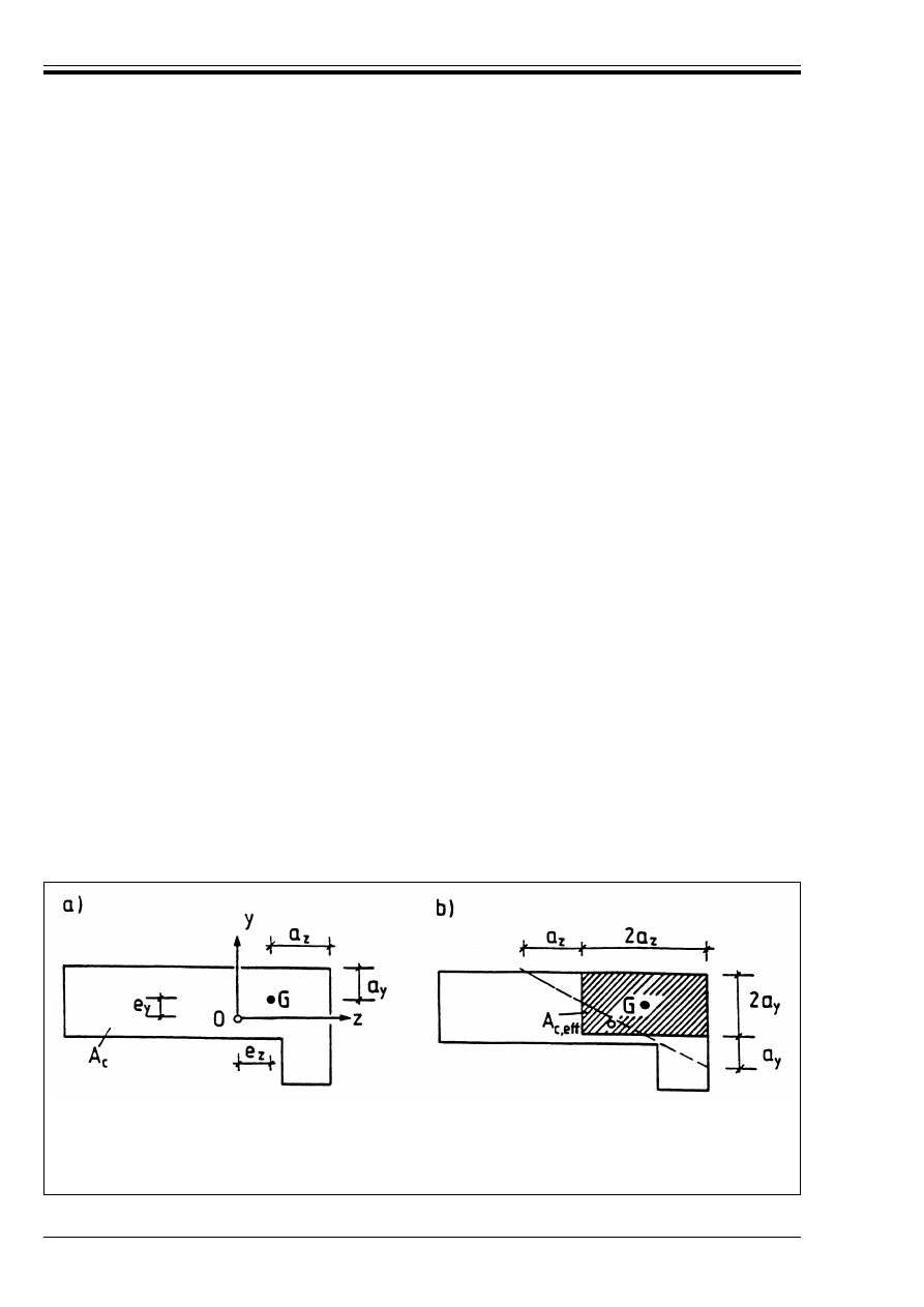
(107) In a cross-section of a plain concrete member, subjected to the design longitudinal force
N
Sd
at a point G with the eccentricities e
y
and e
z
related to the centroid 0 of the
uncracked cross-section A
c
(Figure 4.134), a uniform stress distribution may be
assumed in a part of that cross-section, denoted as the effective section A
c, eff
. The
remaining part of the cross-section may be considered inactive. The resulting
eccentricity e of N
Sd
should, where relevant, include second order effects and
geometrical imperfections (see 4.3.5.3.6 below).
In general, A
c, eff
is limited by a straight secant and its centroid coincides with the
point G. For simplification, A
c, eff
may be taken as rectangular with
A
c, eff
= 2a
z
* 2a
y
(4.185)
where
2a
z
, 2a
y
denote the dimensions of the fictitious rectangle in the z- and y-axis
respectively.
(108) If the effective cross-section is geometrically difficult to define, it may be substituted by
any approximate effective section, included in the cross-section A
c
whose centroid
coincides with the point G, see Figure 4.134.
(109) The resisting design longitudinal compression force N
Rd
is given by:
N
Rd
= – ! * f
cd
* A
c, eff
(4.186)
where
!
is a reduction factor taking account of long-term effects according
to 4.2.1.3.3, b), (11) of ENV 1992-1-1
A
c, eff
Area of effective cross-section.
(110) In the absence of a more rigorous calculation, the design resistance N
Rd
of a
rectangular cross-section with a uni-axial eccentricity e in the direction of h
w
may be
taken as
N
Rd
= – ! * f
cd
* b * h
w
* (1-2e/h
w
)
(4.187)
where
b
Overall width of the cross-section
h
w
Overall depth of the cross-section
e
Eccentricity of N
Sd
in the direction h
w
.
Figure 4.134 — Effective cross-section A
c, eff
in the case of bi-axial eccentricities;
a longitudinal force N
Sd
acts in point G, the centroid of the uncracked
section is located in point O
a) Geometry and notations for the uncracked section
b) Effective cross-section A
c, eff
ENV 1992-1-6:1994
© BSI 01-2000
9
4.3.1.3
Local Failure
4.3.2 Shear
4.3.2.1
General
4.3.3 Torsion
4.3.3.1
Pure Torsion
Replacement of Application Rules (2) and (3), Principle P(4) and Application Rules (5) to (9) in
ENV 1992-1-1 by:
4.3.3.2
Combined effects of actions
4.3.3.2.1 General procedure
Replacement of clause 4.3.1.3 in ENV 1992-1-1 by:
P(101)
Unless measures to avoid local tensile failure of the cross-section have been taken, the
maximum eccentricity of the longitudinal force N
Sd
in a cross-section shall be limited to
appropriate values.
Replacement of clause 4.3.2.1 in ENV 1992-1-1 by:
P(101)
In plain concrete members account may be taken of the concrete tensile strength in the
ultimate limit state for shear, provided that either by calculations or by experience brittle
failure can be excluded and adequate resistance can be ensured.
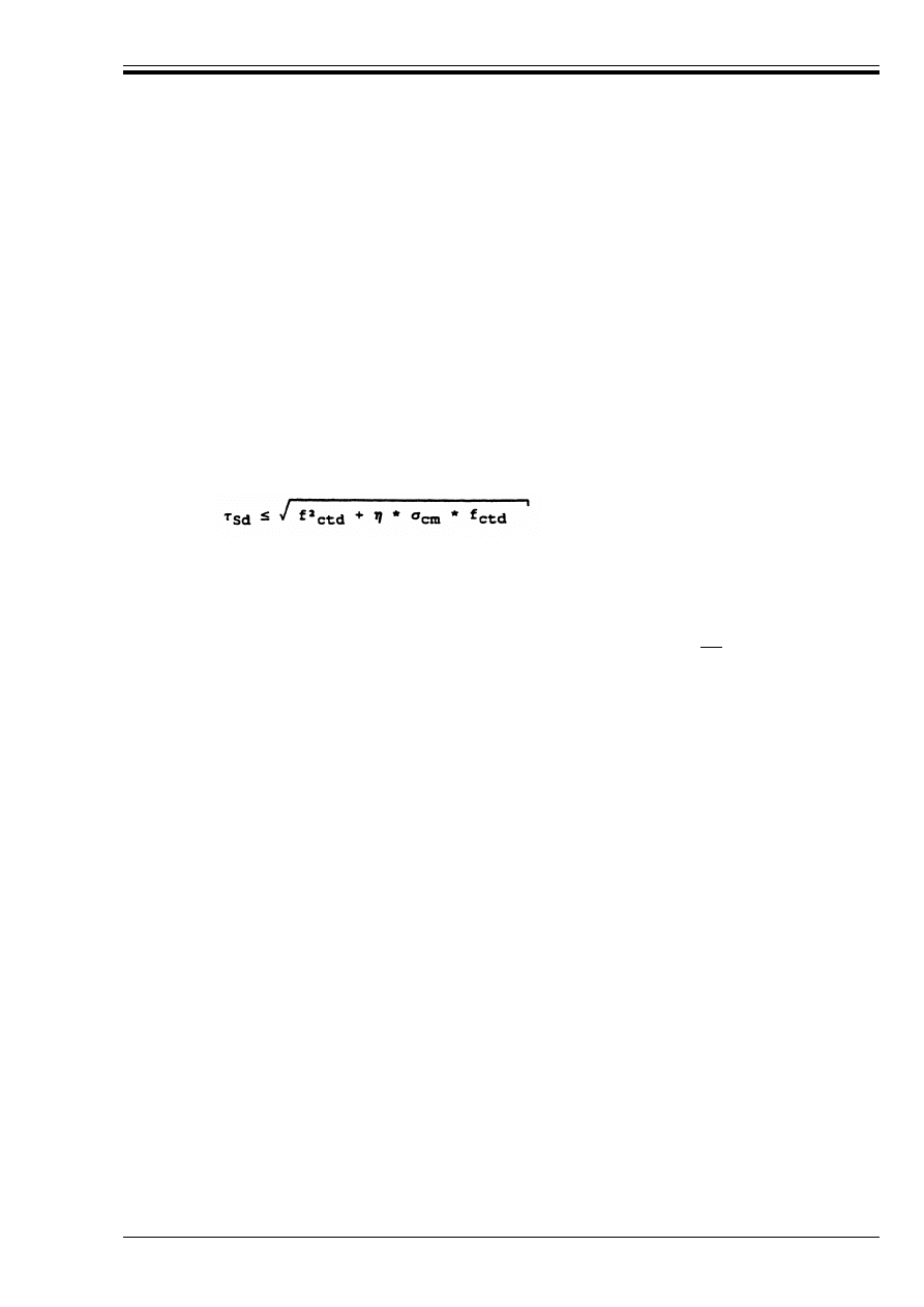
(102) For plain concrete members subjected to a combination of shear, bending and
longitudinal force it should be verified that
(4.188)
where
E
Sd
Design value of the applied shear stress
B
cm
Average concrete compressive stress
f
ctd
= f
ctk0.05
/*
c
, with *
c
according to 2.3.3.2 above.
½
Reduction coefficient. Generally, ½ may be taken as ½ = |1.0|.
According to the actual state of stress, E
Sd
should be calculated for the uncracked, or in
the case of cracks, for the effective section A
c, eff
, see 4.3.1.2 above.
(103) A concrete member may be considered to be uncracked in the ultimate limit state if
either it remains completely under compression or if the principal concrete tensile
stress B
ct1
does not exceed f
ctd
= f
ctk0.05
/*
c
with f
ctk0.05
according to Table 3.1 of
ENV 1992-1-1 and *
c
according to 2.3.3.2 above.
P(102)
Clause 4.3.2.1 of this ENV 1992-1-6 above applies for torsion analogously.
P(103)
Cracked members shall not be considered to resist torsional moments unless adequate
resistance to torsion can be justified.
Addition after Application Rule (4):
P(105)
Clause 4.3.2.1 in this ENV 1992-1-6 applies for torsion combined with shear analogously.

ENV 1992-1-6:1994
10
© BSI 01-2000
4.3.5 Ultimate limit states induced by structural deformation (buckling)
4.3.5.3
Classification of Structures and Structural Members
4.3.5.3.5 Slenderness of Isolated Columns and Walls
Addition to Application Rules (1) and (2) in ENV 1992-1-1:
(103) The slenderness of an isolated column or wall is given by
2 = l
0
/i
(4.189)
where
i
Minimum radius of gyration
l
0
Effective length of the member which can be assumed to be:
l
0
= " * l
w
(4.190)
where
l
w
Clear height of the member
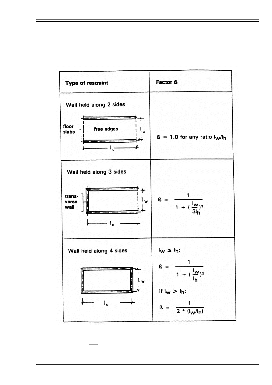
" Coefficient which depends on the support conditions. For columns " = 1 should in general be
assumed, for cantilever columns or walls " = 2. For other walls "-values are given
in Figure 4.135 below.
ENV 1992-1-6:1994
© BSI 01-2000
11
Figure 4.135 assumes that the wall has no openings with a height exceeding |1/3| of the wall height l
w
or
with an area exceeding |1/10| of the wall area. In walls held along 3 or 4 sides with openings exceeding
these limits, the parts between the openings should be considered as held along two sides only and be
designed accordingly.
Figure 4.135 — Factor B for the determination of the effective height l
0
of walls

ENV 1992-1-6:1994
12
© BSI 01-2000
4.3.5.6
Simplified Design Method for Walls and Isolated Columns
(104) The "-values should be increased appropriately if the transverse bearing capacity is affected by
chases or recesses.
(105) Transverse walls may be considered as bracing walls if
— their total depth is not less than |0.5| h
w
, where h
w
is the overall depth of the braced wall;
— they have the same height l
w
as the braced wall under consideration;
— their length l
ht
is at least equal to l
w
/|5|, where l
w
denotes the clear height of the braced wall;
— within the length l
ht
the transverse wall has no openings.
(106) In the case of walls held along two sides which are connected at the top and bottom in flexurally
rigid manner by in-situ concrete and reinforcement so that the edge moments can be fully
resisted, it may be assumed that
" = 0.85 if l
w
< l
h
(4.191)
(107) The slenderness of isolated columns or walls in plain concrete cast in-situ should generally not
exceed 2 = |86| (e.g. l
w
/h
w
= 25). Independently from the actual 2-value, columns are considered
to be slender. However, for compression members with l
w
/h
w
< 2.5, second order analysis is not
necessary.
Replacement of clause 4.3.5.6.3 by:
(101) In absence of a more rigorous approach, the longitudinal force which can be resisted by a slender
column or slender wall in plain concrete may approximately be calculated from:
N
Rd
= – b * h
w
* ! * f
cd
* 9
(4.192)
where
N
Rd
Resisting design compression force of the cross-section
b
Overall width of the cross-section
h
w
Overall depth of the cross-section
!
Reduction factor taking account of longterm effects according to 4.2.1.3.3, b), (11) of
ENV 1992-1-1
The function 9 which allows for the second order effects on the load bearing capacity of
compression members in non-sway buildings is given by:
9 = 1.14 * (1-2e
tot
/h
w
) – |0.020| · l
0
/h
w
(4.193)
where:
9
k 1-2e
tot
/h
w
U 0
e
tot
= e
0
+ e
a
+ e:
(4.194)
e
0
First order eccentricity including, where relevant, the effects of floors (e.g. possible
clamping moments transmitted to the wall from a slab) and horizontal actions;
e
a
Additional eccentricity covering the effects of geometrical imperfections. In absence of
more accurate information, e
a
may be taken as e
a
= 0.5 * l
0
/|200|.
e:
Eccentricity due to creep. As a rule, e: may be neglected because it is already included
in equ. (4.193).

ENV 1992-1-6:1994
© BSI 01-2000
13
4.4 Serviceability limit states
4.4.0 General
5 Detailing provisions
This clause of ENV 1992-1-1 is applicable except as follows:
5.4 Structural members
5.4.7 Plain concrete walls
5.4.7.1
General
5.4.9 Construction joints
Replacement of clauses 4.4.0.1 and 4.4.0.2 in ENV 1992-1-1 by:
P(101) The serviceability of building components in plain concrete shall be ensured by means of suitable
design checks and appropriate detailing.
P(102) Particular care is needed where stresses due to structural restraint are expected to occur.
(103)
Appropriate measures to ensure adequate serviceability may include:
a) with regard to crack formation:
— limitation of concrete tensile stresses to acceptable values;
— provision of subsidiary structural reinforcement (surface reinforcement, tying system
where necessary);
— provision of joints;
— methods of concrete technology (e.g. appropriate concrete composition, curing);
— choice of appropriate method of construction.
b) with regard to limitation of deformations:
— a minimum section size (see 5.4 below);
— limitation of slenderness in the case of compression members.
P(104) Any reinforcement provided in plain concrete members, although not taken into account for load
bearing purposes, shall comply with the durability requirements of section 4.1.3.3 “Concrete
cover” of ENV 1992-1-1.
Replacement of clause 5.4.7.1 in ENV 1992-1-1 by:
(101) The overall depth h
w
of a wall should not be smaller than |120| mm for cast in-situ concrete walls.
(102) Chases and recesses are allowed only if it has been shown that adequate strength and stability can
develop.
New clause:
(101) In construction joints where design concrete tensile stresses are likely to occur, an appropriately
detailed reinforcement should be placed.
ENV 1992-1-6:1994
14
© BSI 01-2000
5.4.10 Strip and pad footings
6 Construction and workmanship
This clause of ENV 1992-1-1 is applicable as deemed appropriate in each case.
7 Quality control
This clause of ENV 1992-1-1 is applicable as deemed appropriate in each case.
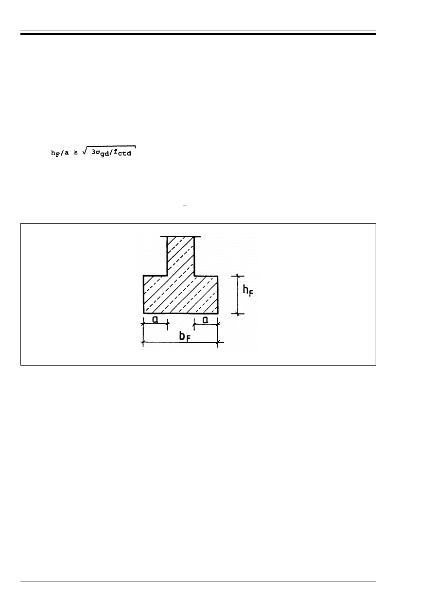
New clause:
(101) In the absence of more detailed data, strip and pad footings approximately axially loaded may be
designed and constructed as plain concrete if the ratio of the foundation depth h
F
to the
projection a from the column face is not less than (see Figure 5.121):
(5.123)
where:
B
gd
is the design value of the ground pressure
f
ctd
is the design value of the concrete tensile strength (in the same unit as B
gd
)
As a simplification the relation h
F
/a U|2| may be used.
Figure 5.121 — Unreinforced pad footings; notations

ENV 1992-1-6:1994
© BSI 01-2000
15
Appendix 1 Additional provisions for the determination of the effects of
time-dependent deformation of concrete
Appendix 1 of ENV 1992-1-1 applies for plain concrete structures.
Appendix 2 Non-linear analysis
Appendix 2 of ENV 1992-1-1 applies as deemed appropriate in each case.
Appendix 3 Supplementary information on the ultimate limit states induced by
structural deformation
Appendix 3 in Part 1-1 of ENV 1992 applies as deemed appropriate in each case.
Appendix 4 Checking deflections by calculation
Appendix 4 in ENV 1992-1-1 applies as deemed appropriate in each case.

DD ENV
1992-1-6:1996
BSI
389 Chiswick High Road
London
W4 4AL
BSI — British Standards Institution
BSI is the independent national body responsible for preparing
British Standards. It presents the UK view on standards in Europe and at the
international level. It is incorporated by Royal Charter.
Revisions
British Standards are updated by amendment or revision. Users of
British Standards should make sure that they possess the latest amendments or
editions.
It is the constant aim of BSI to improve the quality of our products and services.
We would be grateful if anyone finding an inaccuracy or ambiguity while using
this British Standard would inform the Secretary of the technical committee
responsible, the identity of which can be found on the inside front cover.
Tel: 020 8996 9000. Fax: 020 8996 7400.
BSI offers members an individual updating service called PLUS which ensures
that subscribers automatically receive the latest editions of standards.
Buying standards
Orders for all BSI, international and foreign standards publications should be
addressed to Customer Services. Tel: 020 8996 9001. Fax: 020 8996 7001.
In response to orders for international standards, it is BSI policy to supply the
BSI implementation of those that have been published as British Standards,
unless otherwise requested.
Information on standards
BSI provides a wide range of information on national, European and
international standards through its Library and its Technical Help to Exporters
Service. Various BSI electronic information services are also available which give
details on all its products and services. Contact the Information Centre.
Tel: 020 8996 7111. Fax: 020 8996 7048.
Subscribing members of BSI are kept up to date with standards developments
and receive substantial discounts on the purchase price of standards. For details
of these and other benefits contact Membership Administration.
Tel: 020 8996 7002. Fax: 020 8996 7001.
Copyright
Copyright subsists in all BSI publications. BSI also holds the copyright, in the
UK, of the publications of the international standardization bodies. Except as
permitted under the Copyright, Designs and Patents Act 1988 no extract may be
reproduced, stored in a retrieval system or transmitted in any form or by any
means – electronic, photocopying, recording or otherwise – without prior written
permission from BSI.
This does not preclude the free use, in the course of implementing the standard,
of necessary details such as symbols, and size, type or grade designations. If these
details are to be used for any other purpose than implementation then the prior
written permission of BSI must be obtained.
If permission is granted, the terms may include royalty payments or a licensing
agreement. Details and advice can be obtained from the Copyright Manager.
Tel: 020 8996 7070.
Wyszukiwarka
Podobne podstrony:
Eurocode 2 Part 1,4 DDENV 1992 1 4 1994
Eurocode 7 Part 1 DDENV 1997 1 1994
Eurocode 2 Part 2 DDENV 1992 2 1996
Eurocode 4 Part 2 DDENV 1994 2 1997
Eurocode 3 Part 1,1 DDENV 1993 1 1 1992
Eurocode 4 Part 2 DDENV 1994 2 1997
Eurocode 3 Part 1,1 DDENV 1993 1 1 1992
Eurocode 3 Part 1,1 DDENV 1993 1 1 1992
Eurocode 5 Part 1,1 DDENV 1995 1 1 1993
Eurocode 7 Part 2 DDENV 1997 2 1999
Eurocode 9 Part 2 DDENV 1999 2 1998
Eurocode 6 Part 3 DDENV 1996 3 1999
Eurocode 1 Part 4 DDENV 1991 4 1995
Eurocode 2 Part 1,2 prEN 1992 1 2 2004
Eurocode 9 Part 1,1 DDENV 1999 1 1 1998
więcej podobnych podstron