ADVANCED
CATIA V5 Workbook
Knowledgeware and Work Benches
Richard Cozzens
Southern Utah University
www.suu.edu/cadcam
SDC
Schroff Development Corporation
www.schroff.com
www.schroff-europe.com
PUBLICATIONS
Releases 12 & 13
Tutorial Exercises
Knowledgeware
Work Benches
Kinematics
Stress Analysis
Sheetmetal
Design
Prismatic
Machining
Copyrighted
Material
Copyrighted
Material
Copyrighted
Material
Copyrighted
Material
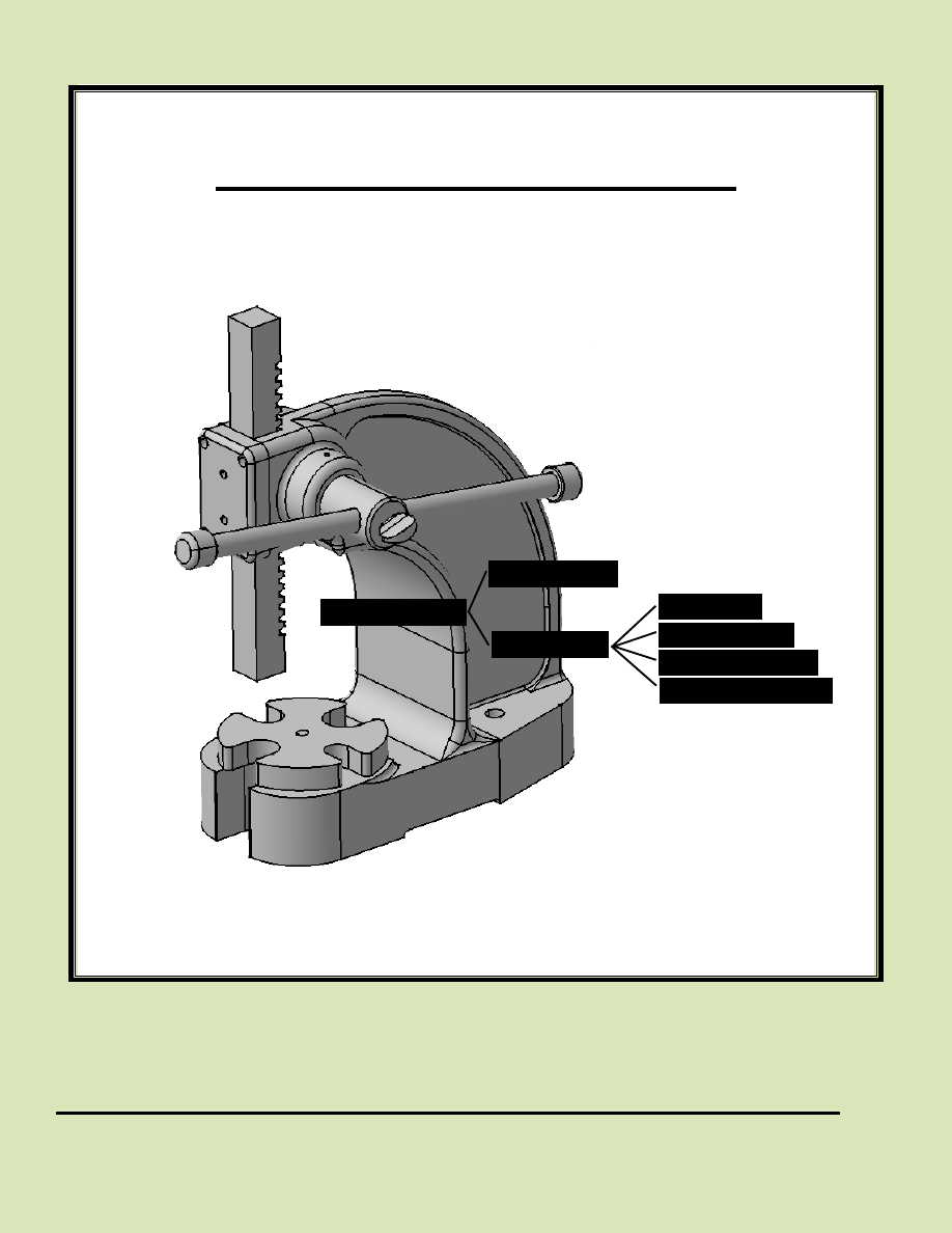
Figure 1.1
Lesson 1
K
nowledgeware
Introduction to CATIA V5 Knowledgeware
Knowledgeware is not one specific CATIA V5 work bench but several work benches.
Some of the tools can be accessed in the Standard tool bar in the Part Design work
bench. Simply put, Knowledgeware is a group of tools that allow you to create,
manipulate and check your CATIA V5 creations.
Copyrighted
Material
Copyrighted
Material
Copyrighted
Material
Copyrighted
Material
1.2
A
dvanced
C
ATIA
V5 W
orkbook
Lesson 1 Objectives
This lesson will take you through the process of automating the creation of joggled
extrusions as shown in Figure 1.1. At the end of the lesson you should be able to do the
following:
1.
Create the Extrusion Profile Sketch and Joggle Profile Sketch.
2.
Assign variable names to the required constraints.
3.
Create the Joggled Extrusion.CATPart using the Rib tool.
4.
Create a spreadsheet with aluminum extrusion dimensions.
5.
Link the spreadsheet to the Joggled Extrusion.CATPart.
6.
Apply the spreadsheet to update the Joggled Extrusion.CATPart.
7.
Create a Macro.
8.
Modify the Macro using VB Script.
9.
Create prompt windows for input using VB Script.
10.
Check for company/industry standards using the Check tool.
11.
Implement the updated Joggled Extrusion.CATPart in a dimensioned drawing.
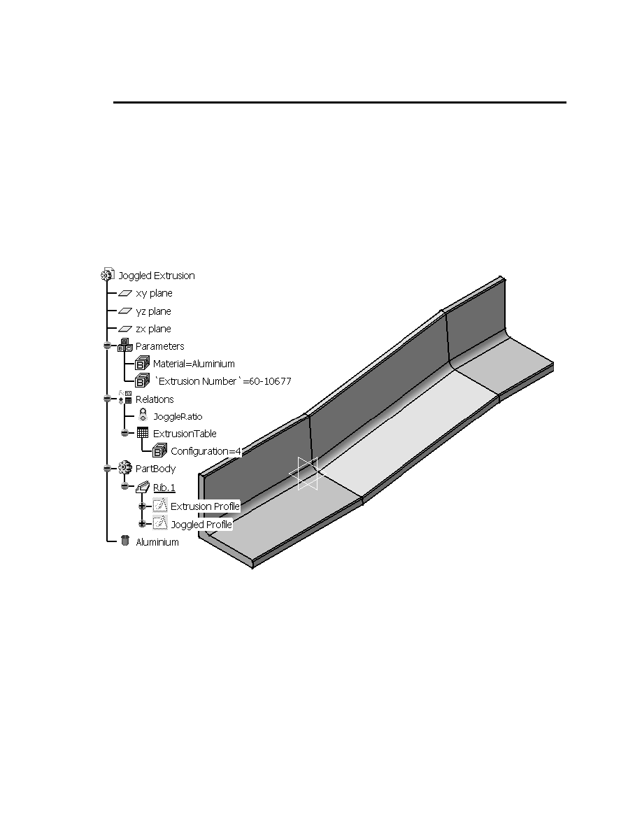
Figures 1.1 and 1.2 show examples of the Joggled Extrusion you will create in this
lesson. Figure 1.1 shows the standard Joggled Extrusion along with its Specification
Tree. Figure 1.2 shows a spreadsheet with the resultant dimensioned drawing.
Figure 1.2
Copyrighted
Material
Copyrighted
Material
Copyrighted
Material
Copyrighted
Material
K
nowledgeware
1.3
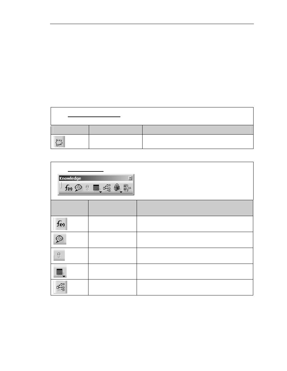
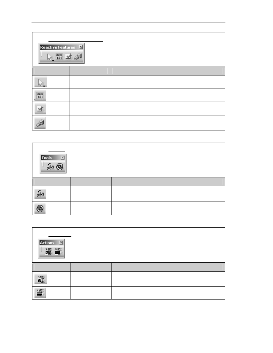
Knowledgeware Work Bench Tools and Tool Bars
A combination of six tool bars is used in this lesson from the Knowledgware Product.
The Knowledgeware Product is made up of the following work benches; Knowledge
Advisor, Knowledge Expert, Product Engineering Optimizer, Product Knowledge
Template, Product Function Optimization and Product Functional Definition. Each
of these work benches has a different combination of tools in each tool bar. If you switch
between any of these work benches you may see the same tool in a different tool bar. For
example the Formula and Design Table tools are accessible from many workbenches in
the bottom tool bar.
The Set of Equations Tool Bar
This tool bar contains only one tool.
TOOL ICON TOOL NAME
TOOL DEFINITION
Set Of Equations
Solves a set of equations.
The Knowledge Tool Bar
TOOL
ICON
TOOL NAME
TOOL DEFINITION
Formula
Creates parameters and determines the
relationship between parameters.
Comment &
URLs
Adds URLs to the user parameters.
Check Analysis
Toolbox
Signals when there has been a violation in a
check and/or rule.
Design Table
Creates and/or imports design tables
(spreadsheets).
Knowledge
Inspector
Queries a design to determine and preview the
results of new parameters.
Copyrighted
Material
Copyrighted
Material
Copyrighted
Material
Copyrighted
Material
1.4
A
dvanced
C
ATIA
V5 W
orkbook
The Reactive Features Tool Bar
TOOL ICON
TOOL NAME
TOOL DEFINITION
Select
Highlights the element you want to select.
Rule
Creates a rule and applies it to your document.
Check
Creates a check and applies it to your document.
Reactions
Creates a script that will change feature attributes.
The Tools Tool Bar
TOOL ICON
TOOL NAME
TOOL DEFINITION
Measure
Update
Updates relationships.
Update
Updates the CATPart and/or CATProduct.
The Actions Tool Bar
TOOL ICON
TOOL NAME
TOOL DEFINITION
Macro with
Arguments
Opens a macro with arguments.
Actions
Creates a script.
Copyrighted
Material
Copyrighted
Material
Copyrighted
Material
Copyrighted
Material
K
nowledgeware
1.5
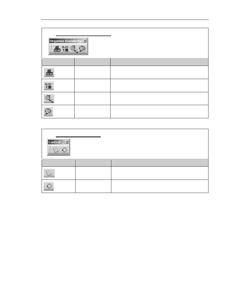
The Organize Knowledge Tool Bar
TOOL ICON
TOOL NAME
TOOL DEFINITION
Add Set of
Parameters
Creates a set of parameters.
Add Set of
Relations
Creates a set of relations.
Parameters
Explorer
Adds new parameters to a feature.
Comment &
URLs
Adds URLs to the user parameters.
The Control Features Tool Bar
TOOL ICON
TOOL NAME
TOOL DEFINITION
List
Manage the objects you want to add to the list
you are creating.
Loop
Interactively apply a loop to an existing
document.

Copyrighted
Material
Copyrighted
Material
Copyrighted
Material
Copyrighted
Material
1.6
A
dvanced
C
ATIA
V5 W
orkbook
The Problem:
One of the many Metalcraft Technologies Inc. (MTI) fabrication processes is fabricating
a joggle in standard and non-standard extrusions. Most of the extrusion requirements are
contained in large assembly mylar sheets. Most of the drawings (mylars) were created in
the early 1970s. It is difficult for the engineer/planner to read and/or measure the mylar
accurately. It may take the engineer/planner 10 to 30 minutes to verify he/she has found
and applied the correct dimensions. It is not productive for the fabricator to also have to
go through the same time consuming process. Having the drawing interpreted so many
times by so many different people will inevitably introduce more chances for error. It is
MTI’s policy that the engineer/planner creates an individual drawing for each joggled
extrusion to avoid such confusion. MTI has minimized the time required to create the
individual drawings by setting up templates and standards. Yet, even with templates and
standards this process is still time consuming. Each drawing is basically the same but has
to be re-created because of a few simple dimensional differences and/or a different type
of extrusion. The goal was to cut this time down by using the intelligence contained in
the existing standard extrusion.
The Solution:
CATIA V5 Knowledgeware tools allow the user to capture and use the intelligence
contained within the standard Joggled Extrusion.CATPart. CATIA V5 macro and
scripting capabilities allow the user to be prompted for the critical dimensions. CATIA
V5 then takes the information and updates the Joggled Extrusion.CATPart according to
the supplied input. CATIA V5 also automatically updates the standard dimensioned
drawing (CATDrawing). The dimensioned drawing is ready to be released to the
production floor in a matter of minutes instead of 30 to 60 minutes.
An additional advantage to this process is adding dimensional checks. If the dimensional
values do not match the company and /or industry standards the user will get a warning.
The following instructions will take you through the steps of creating the standard
Joggled Extrusion.CATPart and then implementing the Knowledgeware solution
described above.

Copyrighted
Material
Copyrighted
Material
Copyrighted
Material
Copyrighted
Material
K
nowledgeware
1.7
Steps to Implementing the Knowledgeware Solution
A parameterized sketch/solid is a basic form of Knowledgeware; it contains intelligence.
Prior to parametric applications you would have to create each variation of the extrusion
from scratch. Parametric applications allow you to modify one constraint and the
extrusion (solid) will update to that constraint.
1. Determine the Requirements
The general problem solving skills apply to implementing the Knowledgeware
solution. You need to list all that is known and unknown and you need to list all of
the variables, for example, what is known.
If you are not sure at first, manually go through the process. You must be able to
create the process manually.
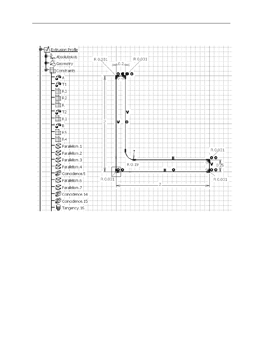
2. Creating the Extrusion Profile Sketch
Create an Extrusion Profile sketch on the ZX Plane as shown in Figure 1.3. The 0,0
point is located at the lower left corner of the extrusion. This sketch will be used as
the standard; all other extrusions will be derived from this basic sketch. When you
complete the sketch, exit the Sketcher work bench but do not use the Pad tool to
create a solid. The solid will be created in Step 8 using a different tool.
Copyrighted
Material
Copyrighted
Material
Copyrighted
Material
Copyrighted
Material
1.8
A
dvanced
C
ATIA
V5 W
orkbook
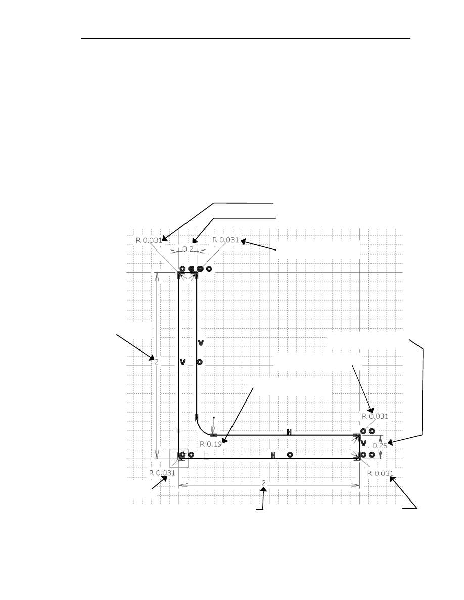
Figure 1.3
3. Constraining the Extrusion Profile Sketch
After completing the rough sketch of the Extrusion Profile sketch as shown in
Figure 1.3 you must constrain it similar to the constrains shown in Figure 1.3.
Copyrighted
Material
Copyrighted
Material
Copyrighted
Material
Copyrighted
Material
K
nowledgeware
1.9
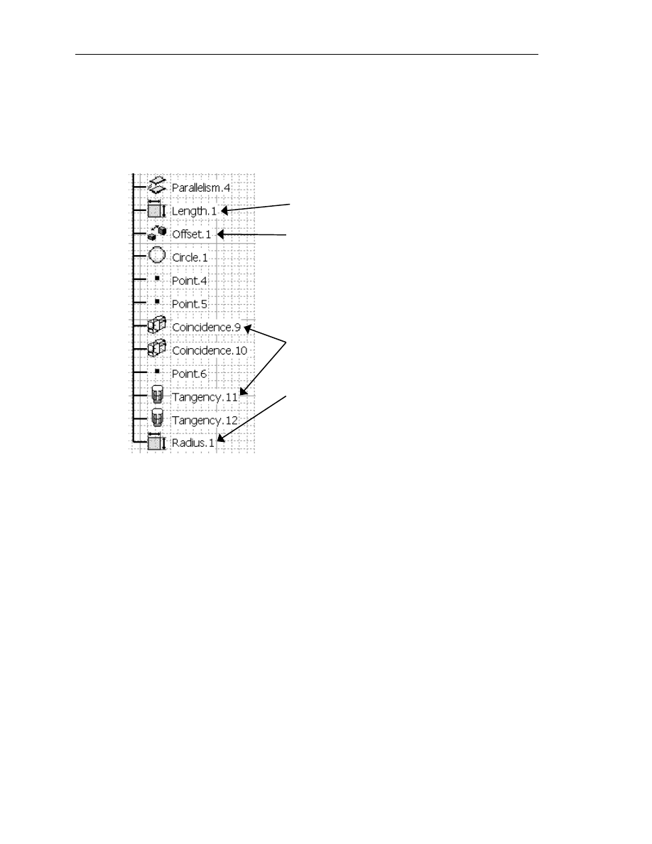
4. Modifying the Constraint Names
In this particular step it is critical that you rename the constraints. Understand that it
is not absolutely necessary, but it will make this process a lot easier if you rename the
constraints with a name that signifies what it is constraining. If you have problems
remembering what the constraint name is, write it down; the names will be required
to create the spreadsheet later in this lesson. It is suggested that you use the
constraint names shown in Figure 1.4 so your information matches what you will see
throughout the remaining steps into this lesson. Also, change the branch name
Sketch.1 to Extrusion Profile. Once you have successfully completed this lesson it is
suggested that you try different variations of this process.
Circle Constraint = R5
Offset Constraint = T2
Figure 1.4
Circle Constraint = R1
Offset Constraint = B
Offset Constraint = T1
Circle Constraint = R2
Circle Constraint = R
Circle Constraint = R3
Offset Constraint = A
Circle Constraint = R4
Copyrighted
Material
Copyrighted
Material
Copyrighted
Material
Copyrighted
Material
1.10
A
dvanced
C
ATIA
V5 W
orkbook
Figure 1.5
Constraint by selecting on line (length)
Constraint between two entities (distance)
Constraint by selecting the radius
Constraint between two entities (distance)
Figure 1.3 shows the constraints in the Specification Tree already renamed. CATIA
V5 will automatically give it a name as shown in Figure 1.5 below.
Complete the following steps to rename the constraints.
4.1
Double click on the constraint that you want to rename. This will bring up
the Constraint Definition window with the constraint value in it.
4.2
Select the More button. This will bring up a Constraint Definition
window as shown in Figure 1.6.
4.3
Edit the current constraint name in the Name box to what you want the new
constraint to be named.
4.4
Select OK. The newly renamed constraint will show up in the
Specification Tree.
Copyrighted
Material
Copyrighted
Material
Copyrighted
Material
Copyrighted
Material
K
nowledgeware
1.11
5.
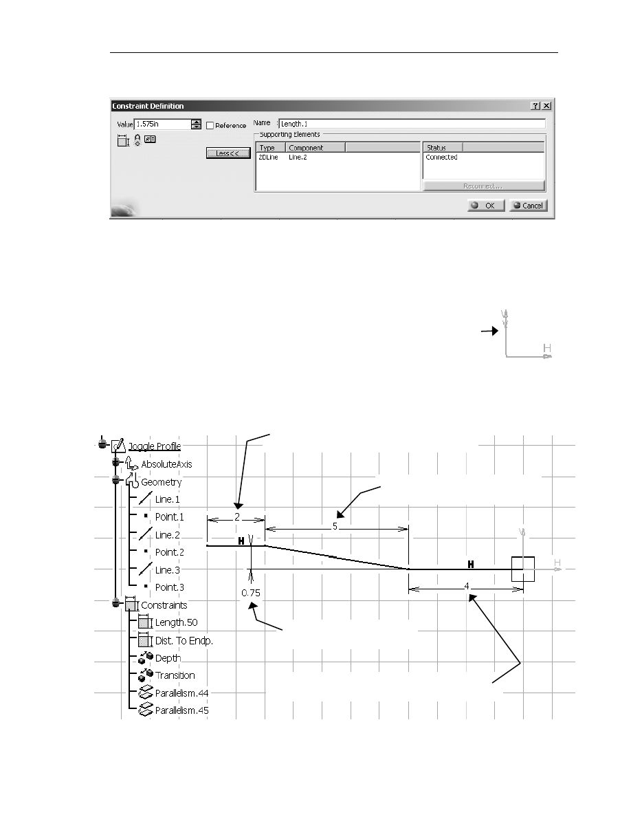
Creating the Profile Sketch of the Joggle
This step, like Step 2, requires you to create another sketch. This sketch
is created on the YZ Plane in the negative direction (notice where the
is located in relation to the sketch in Figure 1.7). Use the information in
Figure 1.7 to create the Joggle Profile sketch.
Figure 1.6
Figure 1.7
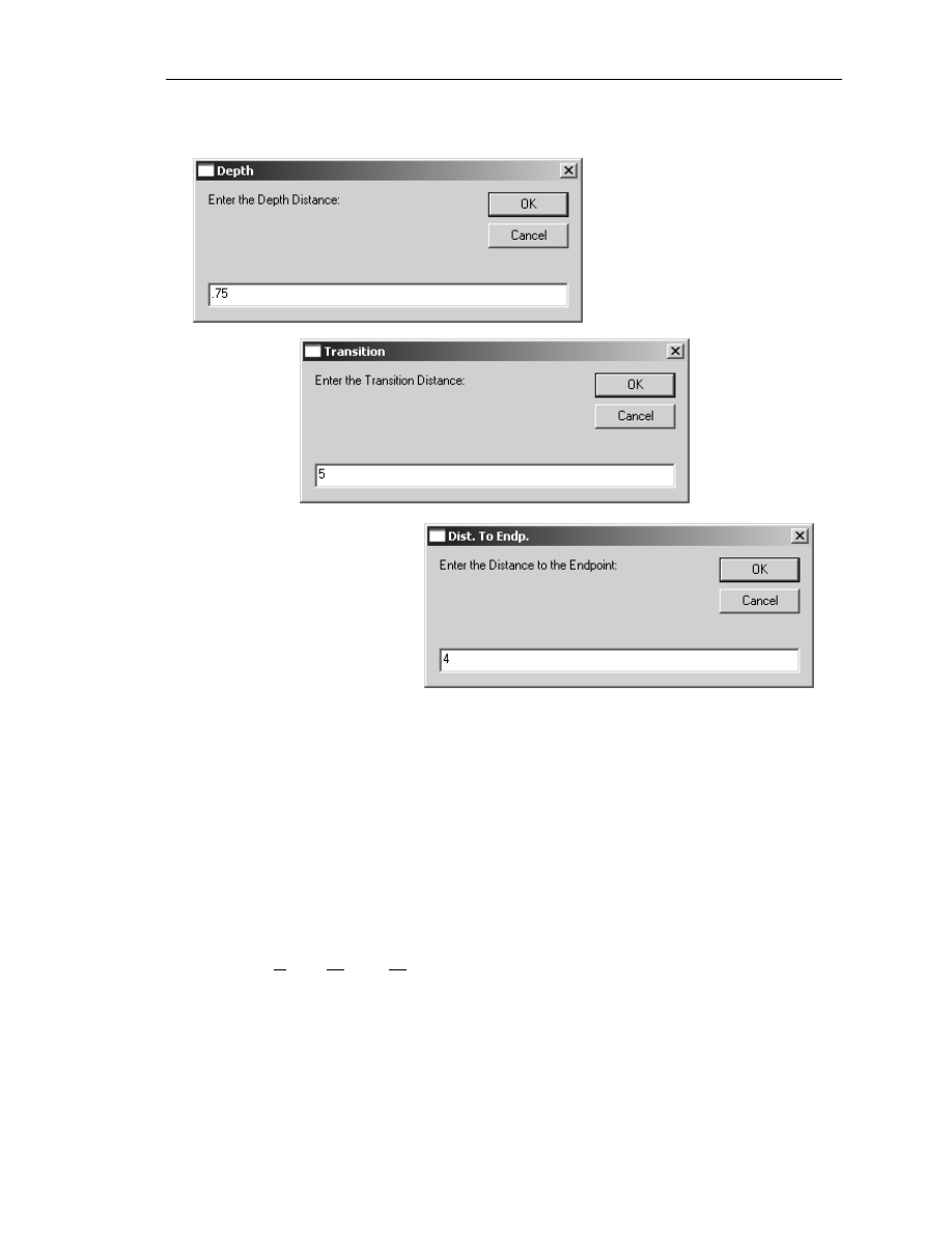
Offset Constraint =
Depth
Offset Constraint =
Transition
Distance Constraint (length) = Dist. To
Endp.
Distance Constraint (length) =
Length.50

Copyrighted
Material
Copyrighted
Material
Copyrighted
Material
Copyrighted
Material
1.12
A
dvanced
C
ATIA
V5 W
orkbook
6. Constraining the Joggle Profile Sketch
Create constraints for the Joggle Profile sketch similar to the ones shown in
Figure 1.7.
7. Modifying the Constraint Names
Modify the constraint names you created in Step 6 to match the constraint names
shown in Figure 1.7. Step 4 describes the process of renaming constraints.
NOTE: It is important that the constraint names be consistent throughout this lesson.
The names will be used to link the information to a table in the next few
steps. If you deviate from the naming convention used in this lesson, the
remaining steps will not work as described.
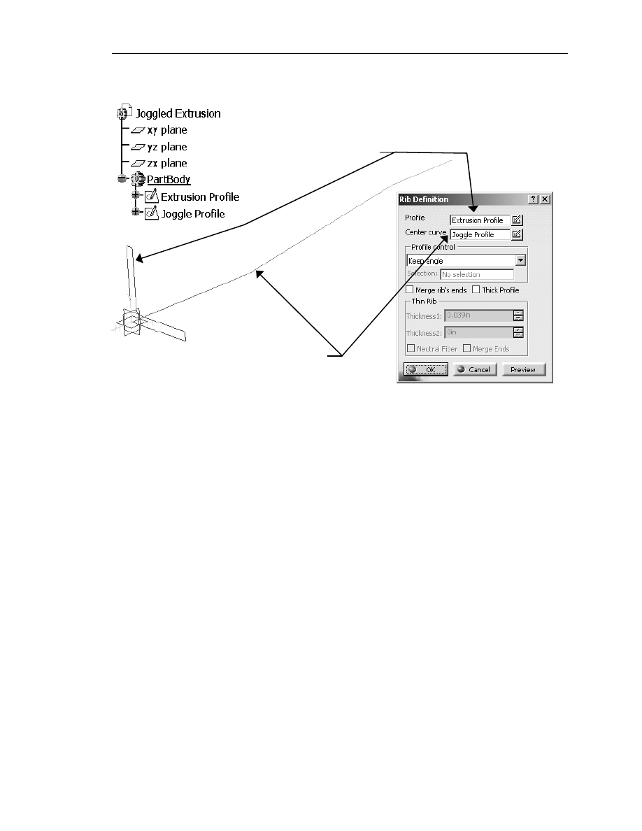
8. Creating a Solid of the Joggled Extrusion
Now that both sketches are created you are ready to create the solid. This will be
accomplished by using the Rib tool found in the Part Design work bench. Complete
the following steps to create the solid
8.1
Select the Extrusion Profile sketch created in Step 2. Make sure it is
highlighted.
8.2
Select the Rib tool found in the Part Design work bench. This will bring up
the Rib Definition window as shown in Figure 1.8. The prompt zone will
prompt you to Define the center curve. The Extrusion Profile will be
listed in the Profile box.
8.3
The Center Curve box should be highlighted. Select the Joggle Profile
either from the geometry or the Specification Tree. CATIA V5 will give
you a preview of the Extrusion Profile being extruded along lines that
define the Joggle Profile sketch.
Copyrighted
Material
Copyrighted
Material
Copyrighted
Material
Copyrighted
Material
K
nowledgeware
1.13
8.4
If the preview looks similar to the joggled extrusion that is shown in Figure
1.9, select the OK button to complete the operation. The Joggled
Extrusion will be made into a solid.
Now that you have created a solid “Joggled Extrusion,” you are ready to go on to the
next step: creating a table of different types of extrusions.
Figure 1.8
Extrusion Profile Sketch
Joggle Profile Sketch
Copyrighted
Material
Copyrighted
Material
Copyrighted
Material
Copyrighted
Material
1.14
A
dvanced
C
ATIA
V5 W
orkbook
9. Creating an Extrusion Table
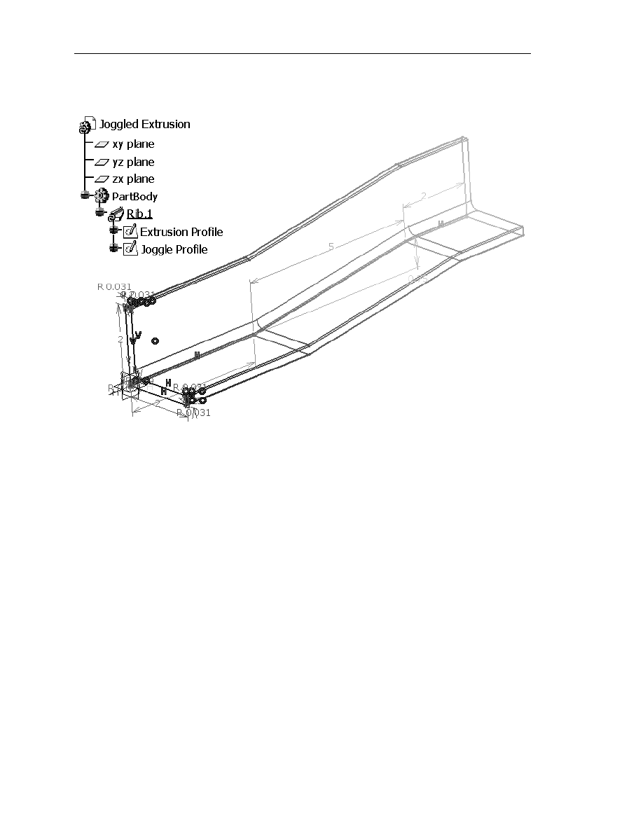
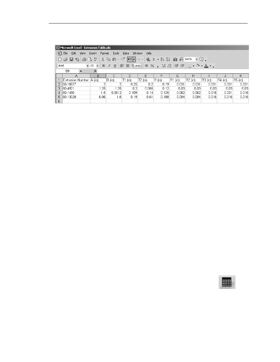
Figure 1.10 is an Excel (Spreadsheet) that contains the dimensions to four different
types of aluminum extrusions. The extrusions and their dimensions were taken from
the Tierany Metals Catalog. You might recognize the extrusion on row 5; it is the
one you created in the previous steps. If you wanted to create the extrusion in row 2
you would have to start from step one again or you could go back to the Extrusion
Profile sketch and revise the constraints. Obviously revising the constraints would be
the quickest and easiest method to creating the new extrusion. CATIA V5
Knowledgeware tools can make this process even quicker and easier. This is
accomplished by linking the Excel File to the CATPart.
Figure 1.9
Copyrighted
Material
Copyrighted
Material
Copyrighted
Material
Copyrighted
Material
K
nowledgeware
1.15
You can use an existing spreadsheet if it is available. If it is not available, you will
have to create your own. The spreadsheet does not have to be an Excel program; any
spreadsheet program will work. Each column requires a header. The header will be
used as a variable link later in the lesson. Notice the column headers used in Figure
1.10 match the constraint names used in the previous steps to create the Extrusion
Profile sketch. This is not absolutely necessary, but it does make the linking process
much more intuitive.
To complete this step, go into the spreadsheet program of your choice and enter the
information in as shown in Figure 1.10. Save the file; preferably in the same
directory that your CATPart file exists. Remember the file name and where it exists
as you will need that information in the following step.
10. Importing the Extrusion Table
CATIA V5 allows you to create a design table inside CATIA V5 or import an
existing design table. This step will show you how to import the design table created
in Step 9. As you go through the process of importing a design table, you will be
able to observe how CATIA V5 allows you the opportunity to create and modify a
design table inside of CATIA V5. To import a design table, complete the following
steps.
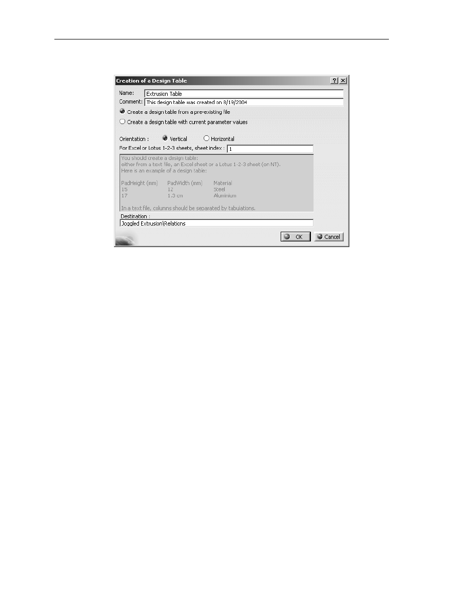
10.1
In the Part Design work bench, double click on the Design
Table tool. The Design Table tool is located in the
Standard tool bar at the bottom of the CATIA V5 screen.
The Design Table tool icon is shown in Figure 1.11. This
will bring up the Creation of a Design Table window as
shown in Figure 1.12.
10.2
Name the design table “Extrusion Table” using the Name box as shown in
Figure 1.12.
Figure 1.11
Figure 1.10
Copyrighted
Material
Copyrighted
Material
Copyrighted
Material
Copyrighted
Material
1.16
A
dvanced
C
ATIA
V5 W
orkbook
Figure 1.12
10.3
The Comment box will automatically place the date of creation. You can
modify this box to any text that might help. This is just a comment box and
will not have any effect on the following steps.
10.4
Select Create a design table from a pre-existing file. Although you will
not use the other choice in this lesson it is important that you know that the
other choice is available. The other choice is Create a design table with
current parameter values. This choice allows you to create a design table
inside CATIA V5.
10.5
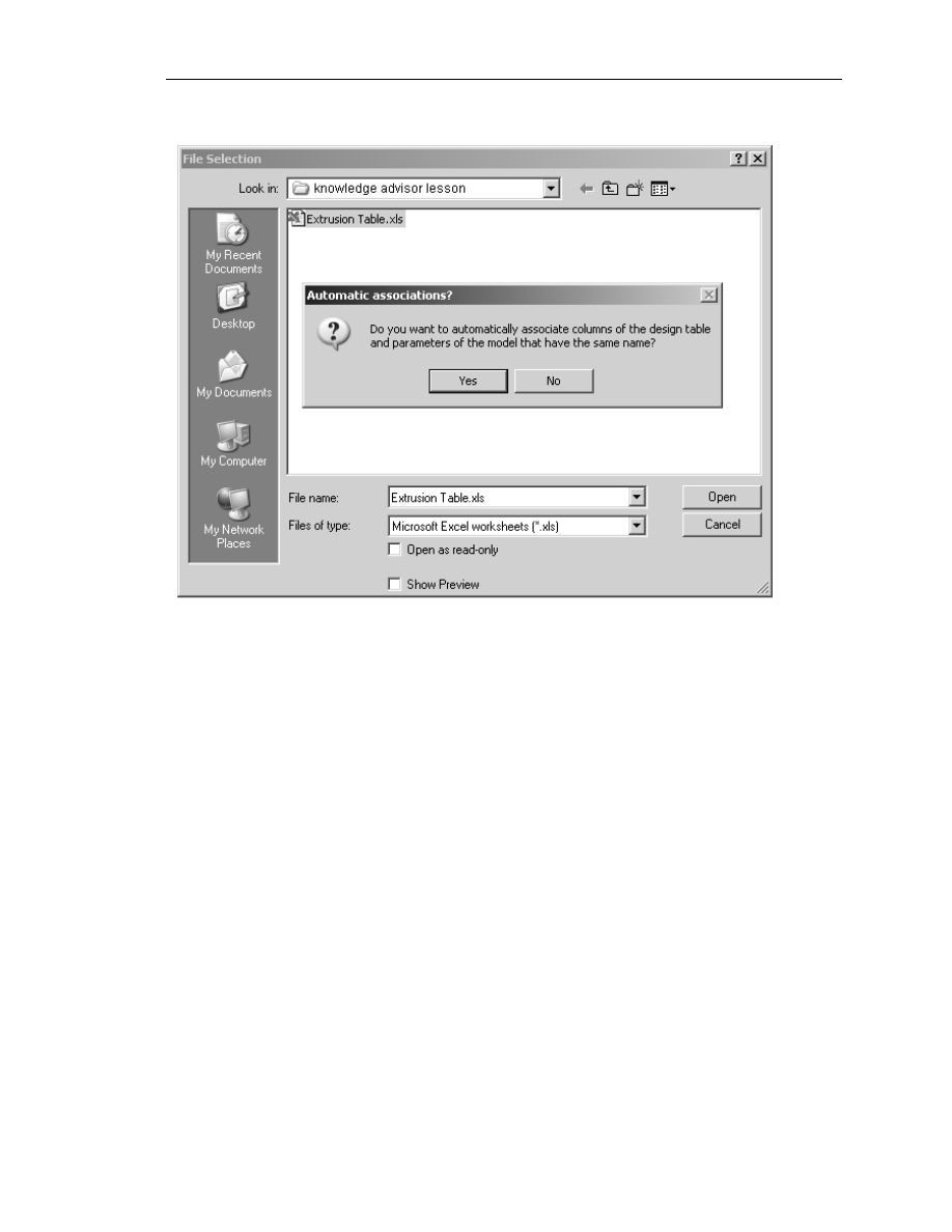
Select the OK button. This will bring up browser window labeled File
Selection. This is the standard Windows file browser. Reference Figure
1.13.
10.6
Select the directory and the file that you want to import. For this step, you
will want to select the Extrusion Table created in Step 9, as shown in
Figure 1.13.
10.7
Select the Open button. This will bring up an Automatic Associations?
window as shown in Figure 1.13. The prompt window asks if you want to
automatically associate the parameters.
10.8
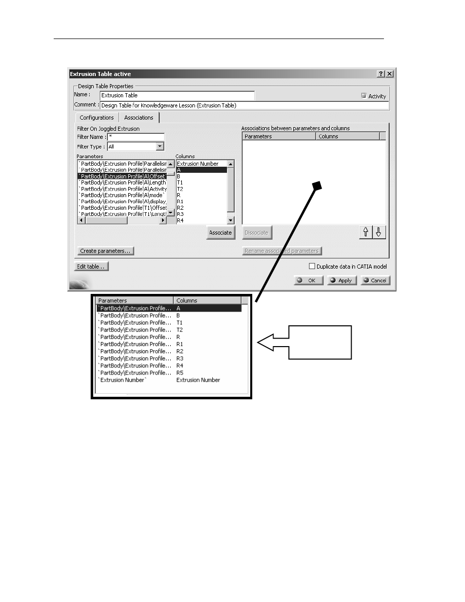
Select Yes. This will bring up the Extrusion Table Active window as
shown in Figure 1.14. Note that Figure 1.14 is shown with the
Associations tab selected, not the Configurations tab. If there are no
associations listed in the Configurations box, CATIA V5 was not able to
automatically associate any of the Constraint Parameters or Extrusion
Table Column Headings.
Copyrighted
Material
Copyrighted
Material
Copyrighted
Material
Copyrighted
Material
K
nowledgeware
1.17
Figure 1.13
10.9
When CATIA V5 is not able to automatically associate the two together,
you will have to manually associate them. To do this, select the
Associations tab in the Extrusion Table Active window as shown in
Figure 1.14.
10.10
The Parameters box lists all the parameters CATIA V5 created in the
Extrusion Profile sketch. A CATIA V5 sketch contains a lot of
parameters that the users are not usually aware of. What makes it more
difficult, is the CATIA V5 naming convention. It is difficult to identify a
CATIA V5 parameter listed in this box to an actual parameter in the
Extrusion Profile sketch. This is where renaming the constraints in the
previous steps will prove to be beneficial. You should be able to scroll
through the Parameters box and identify the constraints you renamed.
All the parameters are represented on two separate lines. For this lesson
you will use the line that ends with a type of measurement such as Radius,
Offset or Length. You will not use the line ending in Activity. For this
step, scroll through the Parameters list; verify the constraints you
renamed in Step 4 are listed.
Copyrighted
Material
Copyrighted
Material
Copyrighted
Material
Copyrighted
Material
1.18
A
dvanced
C
ATIA
V5 W
orkbook
10.11
Select A from the Columns box.
10.12
From the Parameters box, find and select the line ‘PartBody\Extrusion
Profile\A\Length’.
10.13
Select the Associate button. Your two selections from the Parameters
and Columns boxes will show up in the Associations between
parameters and columns box. This means that they were successfully
associated.
10.14
Continue this process until all the variables in the Columns box, except
for Extrusion Number, is matched up to the appropriate parameter. (R,
R1, etc. will of course be a Radius rather than a Length).
Figure 1.14
Box as it appears
after selecting all
parameters.
Copyrighted
Material
Copyrighted
Material
Copyrighted
Material
Copyrighted
Material
K
nowledgeware
1.19
Figure 1.15
10.15
Now you can take care of the Extrusion Number column heading. The
Extrusion Profile sketch has no associative value to the Extrusion
Number that was created in the Extrusion Table. You can assign it one
by selecting the Extrusion Number in the Columns box.
10.16
Select the Create Parameters… button. This will bring up the OK
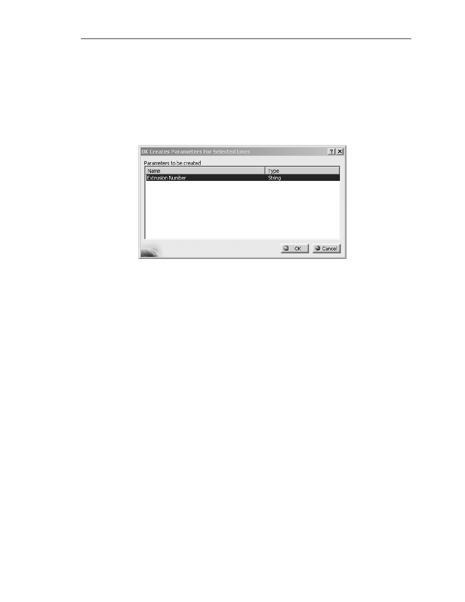
Creates Parameters for Selected Lines window as shown in Figure 1.15.
10.17
Make sure Extrusion Number is selected/highlighted.
10.18
Select the OK button. This will create an association of a string type to
the Extrusion Number heading. The association will be displayed in the
Extrusion Table Active window under the Associations tab along with
all the other associations you created in this step. What this really does for
you is allows the Specification Tree to show the Extrusion Number.
Figure 1.16, under the Parameters branch, displays ‘Extrusion Number’
=60-10677. The string of numbers 60-10677 is linked from the specific
row in the Extrusion Table. If you select another row (extrusion) from
the Extrusion Table the Specification Tree will reflect the change just as
the solid does.
NOTE: In order for the parameters to show up in the Specification Tree you must
have the Options set correctly. Step 13 will show you how to set the
correct options.
10.19
Select the Configurations tab in the Extrusion Table Active window. If
you correctly associated the Parameters and Columns, it should look
similar to the table shown in Figure 1.16. If your window looks similar to
the one shown in Figure 1.16, select the OK button to complete the
association process.
10.20
Doing this will make the window disappear and Extrusion Table.1 shows
up on your Relations branch of the Specification Tree. You may wonder
what else is different. What did you just accomplish? Step 11 will show
you the advantages of what you just accomplished.
Copyrighted
Material
Copyrighted
Material
Copyrighted
Material
Copyrighted
Material
1.20
A
dvanced
C
ATIA
V5 W
orkbook
11. Applying the Extrusion Table to the Joggled Extrusion
The purpose for linking a design table to the CATPart file is to update the part
without having to redraw and/or revise the constraints manually. (Keep in mind that
if you move your saved table, it will break the link and you will need to re-link it.)
To test this, complete the following steps.
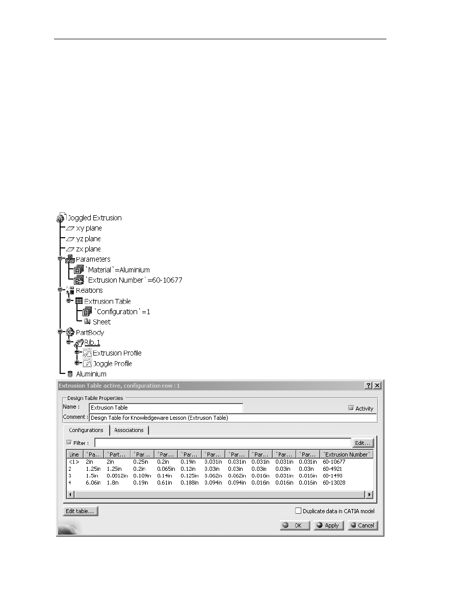
11.1
Double click on Extrusion Table in the Specification Tree. This will
bring up the Extrusion Table Active window as shown in Figure 1.16.
The data in row 1 is currently the active row. There are several methods to
tell which row of data is active.
Figure 1.16
Copyrighted
Material
Copyrighted
Material
Copyrighted
Material
Copyrighted
Material
K
nowledgeware
1.21
Figure 1.17
11.1.1
The window label contains the information: Extrusion Table
active, configuration row: 1.
11.1.2
Row 1 has brackets around it [<1>]. The inactive lines do not
have the brackets around it.
11.1.3
One other method is to check the data against actual extrusion
dimensions. Figure 1.16 and the entire product in the previous
steps represent the data that is contained in row 1.
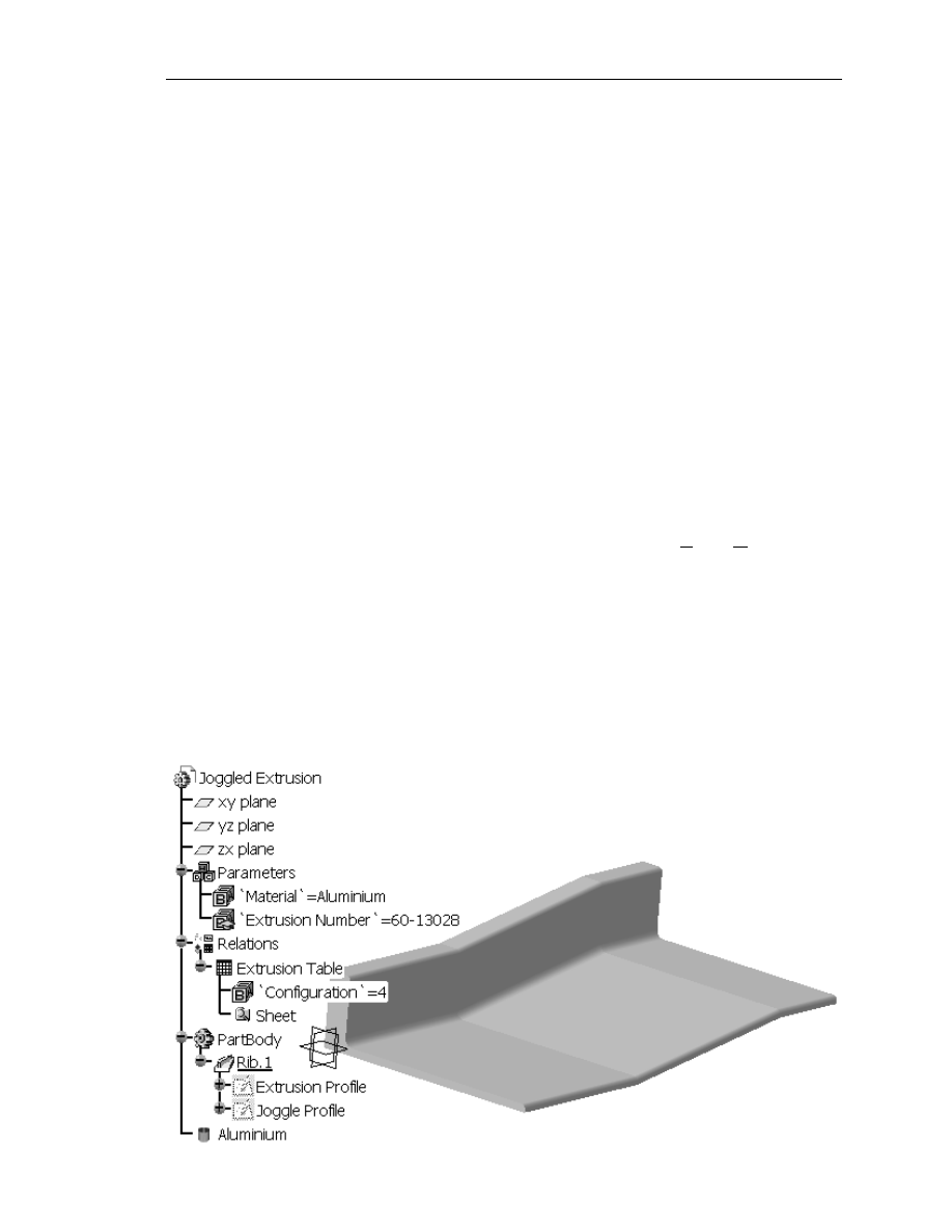
11.2
To make row 4 (Extrusion Number 60-13028) active, select the row. The
existing extrusion will turn red signifying it needs to be updated.
11.3
Select the OK button. This will update your active extrusion to the data
contained in row 4. Figure 1.17 shows the row 4 extrusion. Compare the
differences between the extrusion represented in Figure 1.16 and 1.17.
Verify the extrusions with the dimensions in the Extrusion Table (design
table).
NOTE: If your extrusion does not automatically update you will have to select the
Update button in the Standard tool bar section to force the solid to update.
If you want CATIA V5 to automatically update select Tools, Options,
Infrastructure branch, Part Infrastructure branch, General tab, Update
section and select the Automatic button.
Once you link your Extrusion Table to your CATPart, updating is quite simple.
Click on the Extrusion Table in the Specification Tree to bring up the design table.
Select the row of data you want to apply to the CATPart and select OK. Be sure to
select row 1 (Extrusion Number 60-10677) again before moving on to the next step.

Copyrighted
Material
Copyrighted
Material
Copyrighted
Material
Copyrighted
Material
1.22
A
dvanced
C
ATIA
V5 W
orkbook
12. Editing the Extrusion Table
You now have the Extrusion Table linked to the Joggled Extrusion CATPart. As
the previous step demonstrated, creating new extrusions are only a few clicks away.
Editing the Extrusion Table (design table) is just as easy. Modifying the Extrusion
Table can be done in CATIA V5 or outside of CATIA V5. To modify the
Extrusion Table inside of CATIA V5, complete the following steps.
12.1
Double click on the Extrusion Table in the Specification Tree.
12.2
This brings up the Extrusion Table Active window. Click on the Edit
Table button at the bottom left of the window.
12.3
This brings up the original spreadsheet that the Extrusion Table was
created in. Modify the number 2 in row 2 (Extrusion Number 60-10677)
and column C (header B (in)) to a 4.
12.4
Save and exit the revised spread sheet program. CATIA V5 will notify you
that the Extrusion Table has been revised. Select Close to update the link.
12.5
The part will turn red because it is the active row. Select OK to update the
Joggled Extrusion CATPart.
Your part is now updated to the information edited into the spreadsheet without
leaving CATIA V5. You can use this method to add rows of new information, in
this case additional extrusion types. You can also delete rows of information. The
second method of revising the spreadsheet is editing the spreadsheet outside of
CATIA V5. CATIA V5 will still give you a warning and a chance to accept or reject
the revised spreadsheet.
NOTE: 2″ is correct for the 60-10677 Extrusion Number, so be sure to change it
back.
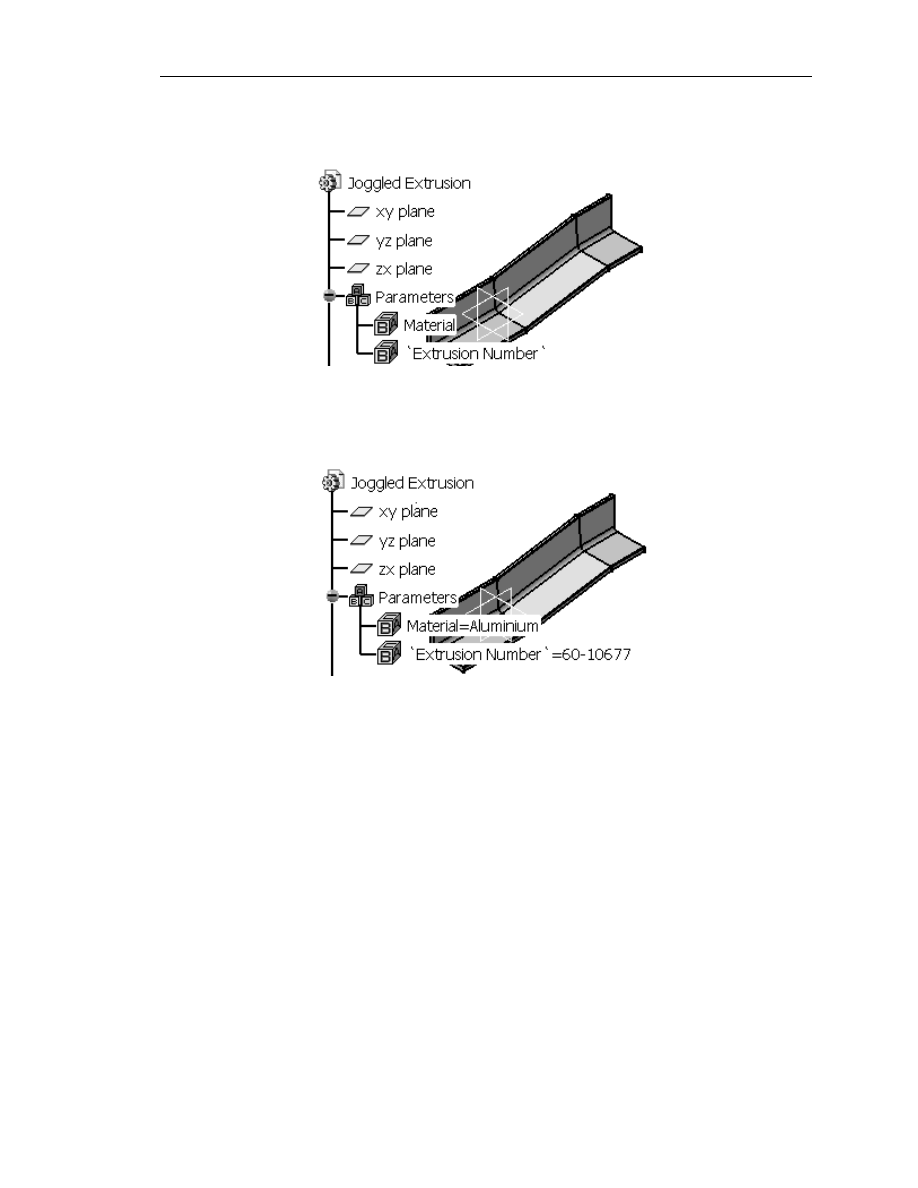
13. Displaying the Extrusion Type in the Specification Tree
Figure 1.18 shows the Specification Tree without the value displayed, and Figure
1.19 shows the Specification Tree after the following process to display the value.
Select Tools, Options, Parameters and Measure under the General branch,
Knowledge tab, Parameters Tree View section; check the With Value box.
Copyrighted
Material
Copyrighted
Material
Copyrighted
Material
Copyrighted
Material
K
nowledgeware
1.23
14. Modifying the Existing Joggle Profile Sketch
The previous steps showed you how to create, select and automate the creation of
different types of extrusions. This was accomplished using a spreadsheet and the
Extrusion Profile sketch. The following step will show you how to apply joggle
information to the selected extrusion. This step uses/modifies the Joggle Profile
sketch. If joggle information was standardized, you could create a spreadsheet with
the required information and apply it to the Joggle Profile sketch as you did to the
Extrusion Profile sketch. Joggle information is not standard; it is as varied as the
parts and assemblies they are applied to. With the help of Knowledgeware this
process can still be automated by getting information directly from the user in the
place of the spreadsheet.
For this step, revise all the constraints in the Joggle Profile sketch to match the
constraints shown in Figure 1.16.
Figure 1.18
Figure 1.19
Copyrighted
Material
Copyrighted
Material
Copyrighted
Material
Copyrighted
Material
1.24
A
dvanced
C
ATIA
V5 W
orkbook
Figure 1.20
The following steps will show you how this is accomplished. This step will start out
real basic so you can better appreciate the power of CATIA V5’s Knowledgeware.
The Joggle Profile sketch controls the joggle of the extrusion. If you want to
change the joggle depth, you could go into the Joggle Profile sketch and revise the
constraint that controls the depth. Figure 1.7 shows that value of Depth is currently
.75″. Entering the Joggle Profile sketch and modifying all the constraints for every
individual part becomes very repetitious and time consuming. The following steps
will show you how Knowledgeware can help you automate this process.
15. Automating the Modification Using a Marco
This step is similar to what was explained in Step 12. You go through the same
steps except that you turn on the Macro Recorder to record everything you do. To
accomplish this, complete the following steps.
15.1
Enter the Joggle Profile sketch, as shown in Figure 1.7. The first thing you
need to remember is to record only what is necessary, other wise you get a
lot of information that only complicates the process.
15.2
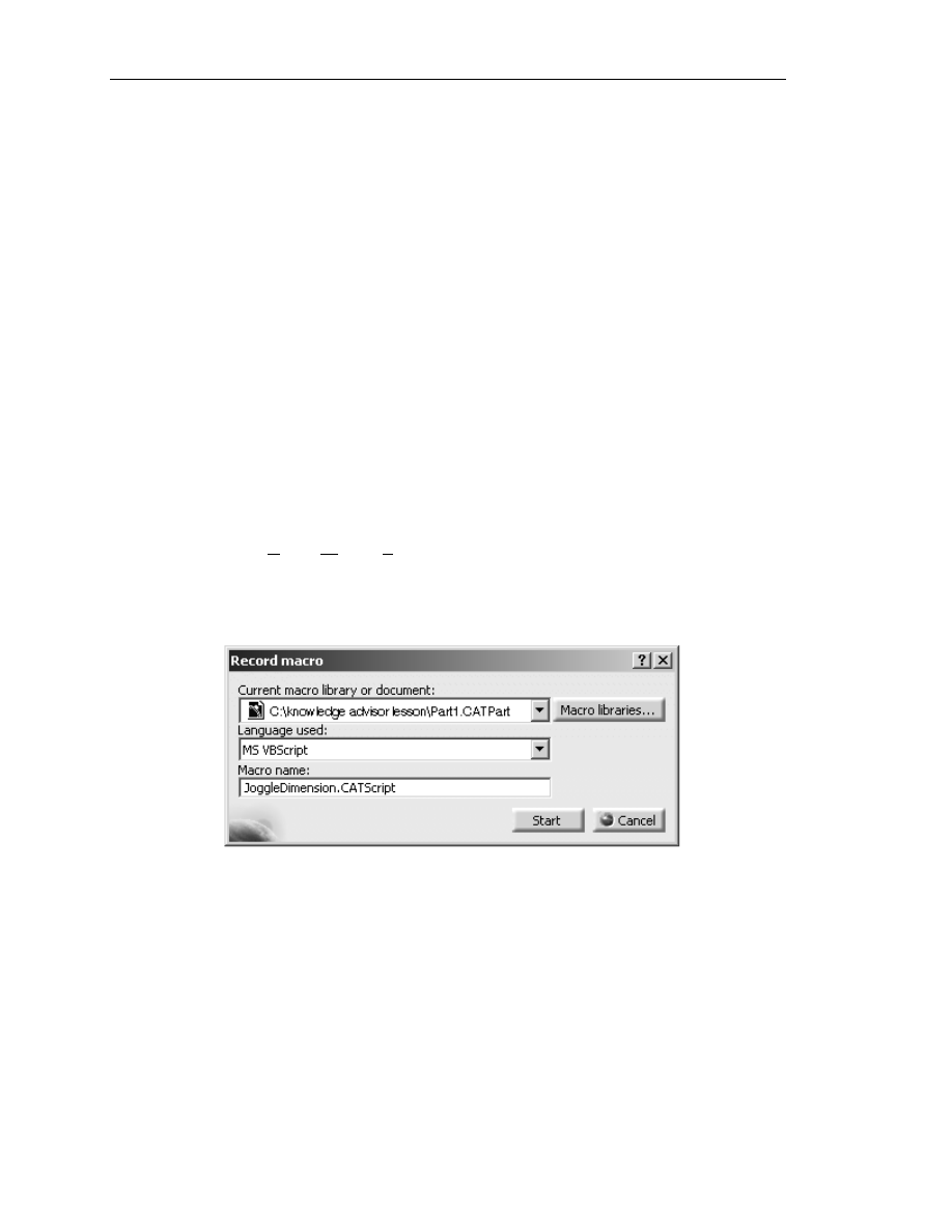
Select Tools, Macro, Start Recording. This will bring up the Record
Macro window as shown in Figure 1.20.
15.3
The Current Macro Library Or Document: should default to your
CATPart at its designated saved location. Select CATScript for the
Language Used: box.
15.4
Name the macro “JoggleDimensions.CATScript.” CATIA V5 will
default the name to Macro1.catvbs unless you specify a name. You must
also add the .CATScript extension. Adding the extension allows CATIA
V5 to save the macro externally not only as a macro but also a CATScript.
Copyrighted
Material
Copyrighted
Material
Copyrighted
Material
Copyrighted
Material
K
nowledgeware
1.25
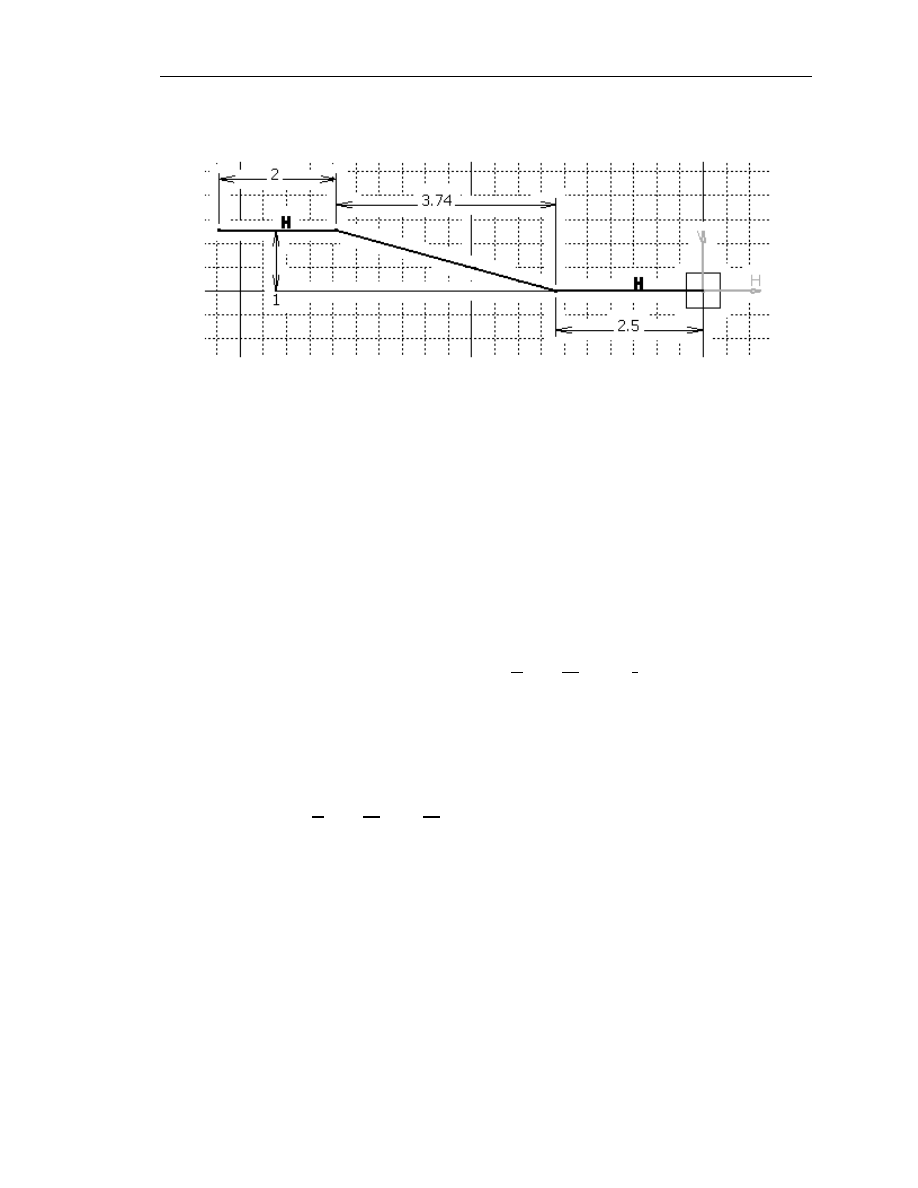
Figure 1.21
15.5
Before you start recording, make sure you know from start to finish what
you are going to record. In this step you are going to modify all of the
constraints in the Joggle Profile sketch to match the constraints shown in
Figure 1.21. Select the Start button to start recording. Notice when you
start recording, CATIA V5 creates a Stop Recording tool bar with a Stop
Macro Recording tool on it.
15.6
Revise the constraints to match the constraints shown in Figure 1.21 in the
following order: .75 to 1.0 (Depth), 5 to 3.74 (Transition), and 4 to 2.5
(Dist. To Endp.).
15.7
Stop the recording. You can stop the recording by selecting the Stop
Macro Recording tool in the Stop Recording window explained in Step
15.4. Another method is to select Tools, Macro, Stop Recording.
15.8
Now go back to the Joggle
Profile sketch and change the constraints to the previous values; the values
shown in Figure 1.7.
15.9
Exit the Sketcher work bench.
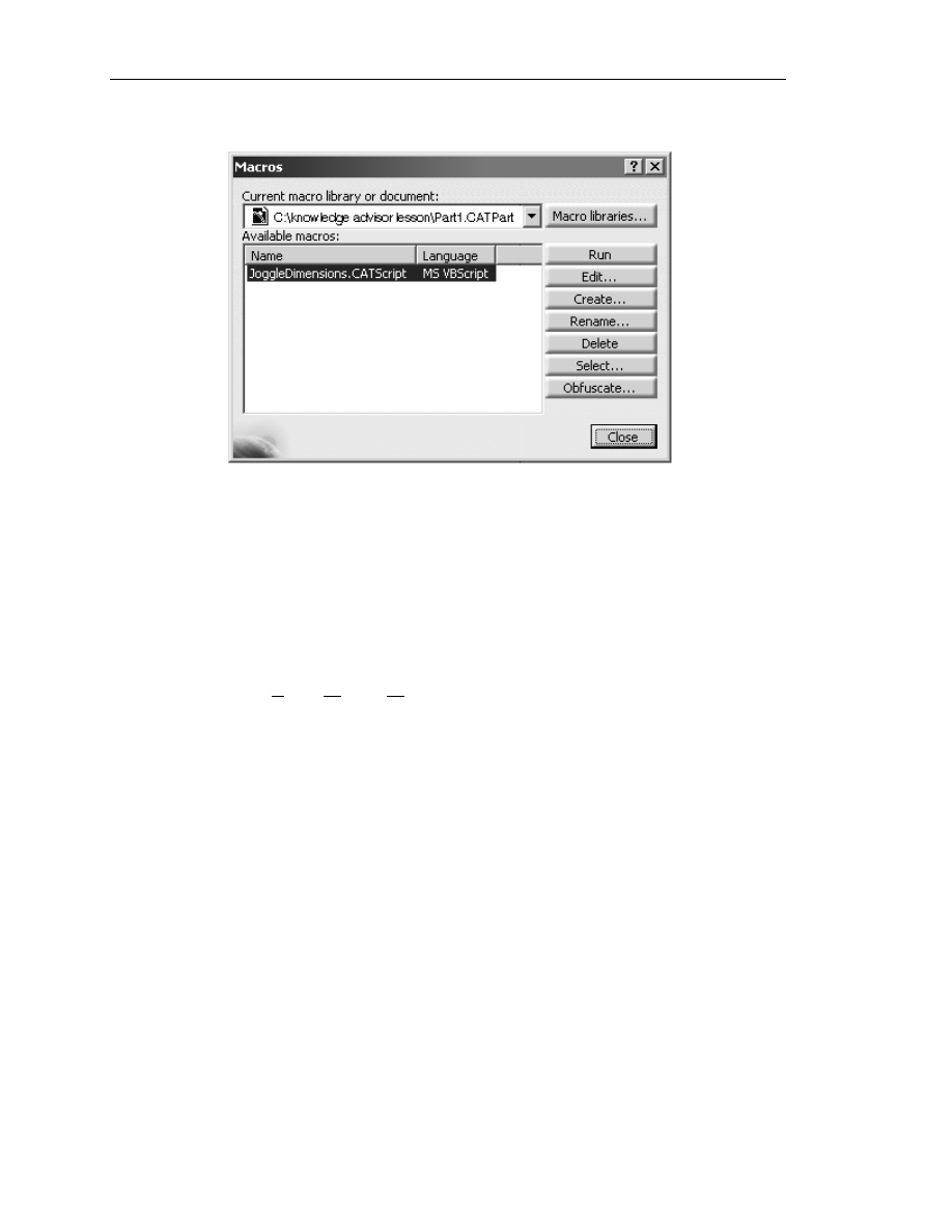
15.10
Select Tools, Macro, Macros. This will bring up the Macros window as
shown in Figure 1.22. Select the JoggleDimensions.CATScript macro.
Copyrighted
Material
Copyrighted
Material
Copyrighted
Material
Copyrighted
Material
1.26
A
dvanced
C
ATIA
V5 W
orkbook
15.11
Select the Run button. This will run the JoggleDimensions.CATScript
macro. Notice your Joggled Extrusion.CATPart will turn red and then
update to the joggled dimensions you created in the macro.
15.12
The previous step demonstrates the result of the macro/script you just
created. As you recorded the macro, CATIA V5 translated the action into
the VBScript Language. CATIA V5 allows you to view and edit the
scripted language. To view the VBScript Language you just created,
select Tools, Macro, Macros, and then select the
JoggleDimensions.CATScript file in the Macros window.
15.13
Select the Edit button. This will bring up the Macros Editor window
shown in Figure 1.23.
The macro function is a powerful tool when it comes to accomplishing a process that
is repeated over and over. The real power of the macro or CATScript you just
created will be shown to you in the next step.
Figure 1.22

Copyrighted
Material
Copyrighted
Material
Copyrighted
Material
Copyrighted
Material
K
nowledgeware
1.27
Figure 1.23
Second constraint that
was revised
(Transition) from 5.0
to 3.74.
First constraint that
was revised (Depth)
from .75 to 1.0
Third constraint that
was revised (Dist. To
Endp.) from 4.0 to 2.5.
Copyrighted
Material
Copyrighted
Material
Copyrighted
Material
Copyrighted
Material
1.28
A
dvanced
C
ATIA
V5 W
orkbook
Figure 1.24
Add these three lines to
prompt the user for
input for Depth,
Transition, and Dist.
To Endp.
Replace the value of
Length1 with
“Depth*(25.4)” variable.
Replace the value of
Length2 with
“Transition*(25.4)”
variable.
Replace the value of
Length3 with
“JoggleLocation*(25.4)”
variable.
16. Customizing the Macro Using VBScript
CATIA V5 Knowledgeware allows you to customize the CATScript using
VBScript Language. This customization makes the Macro and Scripting
capabilities of CATIA V5 Knowledgeware almost limitless. You don’t have to be a
VBScript guru to take advantage of this tool, but obviously the more you know
about it the more powerful a tool it becomes. This step will show you how to add
the constraint variables you created in the Joggle Profile sketch in the previous
steps. To accomplish this complete the following steps.

Copyrighted
Material
Copyrighted
Material
Copyrighted
Material
Copyrighted
Material
K
nowledgeware
1.29
16.1
The macro you created in Step 15 assigned the constant value of 25.400000
to the first constraint you modified when recording the macro. The macro
recorded the value as length1.Value. You will need to find the line where
length1.Value is assigned the length. Figure 1.24 points out the
approximate location of this line.
16.2
Insert the three lines indicated in Figure 1.24 above the line with the value
as length1.Value. The purpose of doing this is to create prompt windows
for the variables you are about to assign in place of the constant values that
are assigned manually. Just adding variables would do you no good; you
need some method of entering a value for the variables that you will create.
The prompt window will allow the user to enter a value for the variable.
(Make sure you type in the syntax exactly as it is shown.)
NOTE: It is obvious that each line represents a specific constraint variable. Depth
is the variable. InputBox is VBScript syntax that creates a prompt
window. Enter the Depth Distance is the text that will show up in the
prompt window header. Depth at the end of the syntax creates a value
input box.
16.3
Now back to the line that has the value as length1.Value. The macro
converted the constant value to metric (mm). You will want to keep the
units in inches so multiply the Depth value by 25.4. The variable name
used for the first constraint is Depth*(25.4). This will convert the value
back to inches. Reference Figure 1.24. Your modified line should look
like similar to the line that is referenced.
16.4
Find the line that assigns length2.Value, the value you changed the
constraint to in Step 15. Change the value to the variable constraint named
“Transition*(25.4).” This variable needs to be converted back to inches as
the one in Step 16.3 did. Reference Figure 1.24 to find the approximate
location of the linen and for the way the revised line should look.
16.5
Find the line that assigns length3.Value, the value you changed the
constraint to in Step 15. Change the value to the variable constraint named
“DistToEndp*(25.4).” This variable also needs to be converted back to
inches in the same method used in Steps 16.3 and 16.4. Reference Figure
1.24 to find the approximate location of the line and for the way the revised
line should look.
16.6
Save the changes and then close the Macros Editor window. The Macros
window will still be available - don’t close it.

Copyrighted
Material
Copyrighted
Material
Copyrighted
Material
Copyrighted
Material
1.30
A
dvanced
C
ATIA
V5 W
orkbook
It is important that you understand the relationship between the constraint that you
renamed in Step 5 and the variable name that you are editing into the VBScript file.
If you get them mixed up you could be changing things in ways you didn’t expect.
You must be sure and follow the VBScript syntax or it will not work. When editing
the lines, make sure they match the lines pointed out in Figure 1.24 exactly.
Reference the CATIA V5 online help and/or a VBScript manual for more in-depth
information on VBScript syntax.
17. Testing the Customized Macro
This step will take you through the process of updating your Joggled Extrusion by
running the macro. This will be a good test to see if you have entered all the syntax
as required.
17.1
The Macros window should still be on the screen. Select the Run button.
17.2
This should bring up the first of the three prompt windows that were
created previously (Depth). Reference Figure 1.25. Type in the original
value assigned in Step 5 (.75), then select OK.
17.3
This will take you to the next prompt window (Transition). Again type in
the original value (5) and then select OK.
17.4
The last prompt window created (Dist. To Endp.) will appear. Type in the
original value (4) and select OK.
17.5
If the syntax was set up correctly, your extrusion should update
automatically or turn red to indicate updating is needed. Your extrusion
should be back to its original configuration.
Copyrighted
Material
Copyrighted
Material
Copyrighted
Material
Copyrighted
Material
K
nowledgeware
1.31
Figure 1.25
18. Creating a Tool Icon for the Macro
The macro (JoggleDimensions.CATScript) created and modified in the previous
steps is a very powerful tool. CATIA V5 has developed another powerful tool that
will save you additional time. This tool allows you to customize your CATIA V5
work environment by creating your own tool icons. Every time you wanted to run
the JoggleDimensions.CATScript macro you could go through the same process of
selecting Tools, Macro, Macros, select the macro, select Run, and finally be ready
to run the macro; or, you could assign the macro a tool icon and just select the tool
icon. Creating a tool icon for the macro would save five steps every time. The
following steps show you how to assign a tool icon to the macro.
Copyrighted
Material
Copyrighted
Material
Copyrighted
Material
Copyrighted
Material
1.32
A
dvanced
C
ATIA
V5 W
orkbook
Figure 1.26
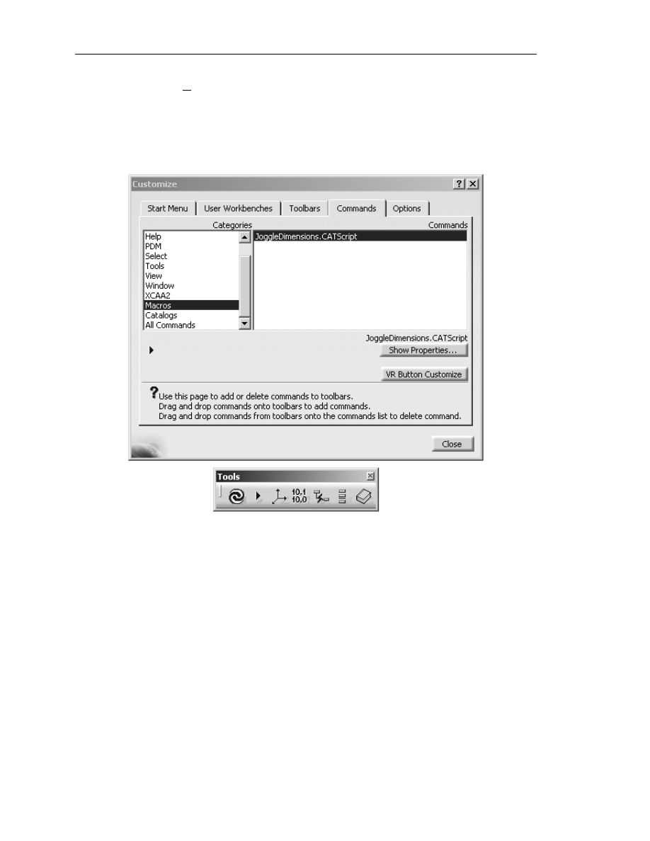
18.1
Select Tools and then select the Customize option
18.2
This will bring up the Customize window as shown in Figure 1.26.
18.3
Select the Commands tab in the Customize window.
18.4
Select Macros from the Categories box. This will bring up all the macros
that were created and saved with the *.CATScript extension.
18.5
Select the JoggleDimensions.CATScript located in the Commands box.
18.6
With the JoggleDimensions.CATScript file highlighted, drag it to the
Tools tool bar. Drop the JoggleDimensions.CATScript on the tool bar as
shown in Figure 1.26.
18.7
Close the Customize window and click on the newly created tool icon.
This will start the JoggleDimensions.CATScript macro.
Copyrighted
Material
Copyrighted
Material
Copyrighted
Material
Copyrighted
Material
K
nowledgeware
1.33
Figure 1.27
As you can see on the Customization window, CATIA V5 allows you many
different ways to customize your CATIA V5 work environment. This step has
shown you only one. Finding and using the tool from the tool bar is easier than
going into the Macro option and searching for the macro.
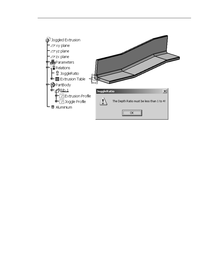
19. Applying Correct Processes and Standards Using
the Check Tool
Currently the JoggleDimensions.CATScript macro will accept the value of 1″ for
the Transition dimension and 5″ for the Depth dimension. Any experienced joggle
operator would tell you that is not a reasonable ratio for an aluminum extrusion. A
safe standard for aluminum extrusions is about 4 (run or Transition) to 1 (rise or
Depth). This is a basic standard, but not every one is aware of it. It is very possible
that the engineer/planner creating the drawing is not aware of the standard, thus
could violate the standard. The engineer/planner could spend time planning and
drawing the Joggled Extrusion. The part could use up time and resources being
prepped for the joggle operation. Only after the extrusion gets to the joggle process
would it be discovered that the joggle dimensions are not within company and/or
industry standards. All of the time, material and resources have gone to waste. All
of this could have been avoided if the engineer/planner was aware of the standard.
One sure way to safeguard yourself and/or company from such mistakes is by
incorporating the standard into the intelligence of the part. CATIA V5 offers you
the tools to capture the knowledge and/or standard and apply it to your CATParts.
The following step explains how to incorporate the JoggleRatio standard to your
Joggled Extrusion.CATPart.
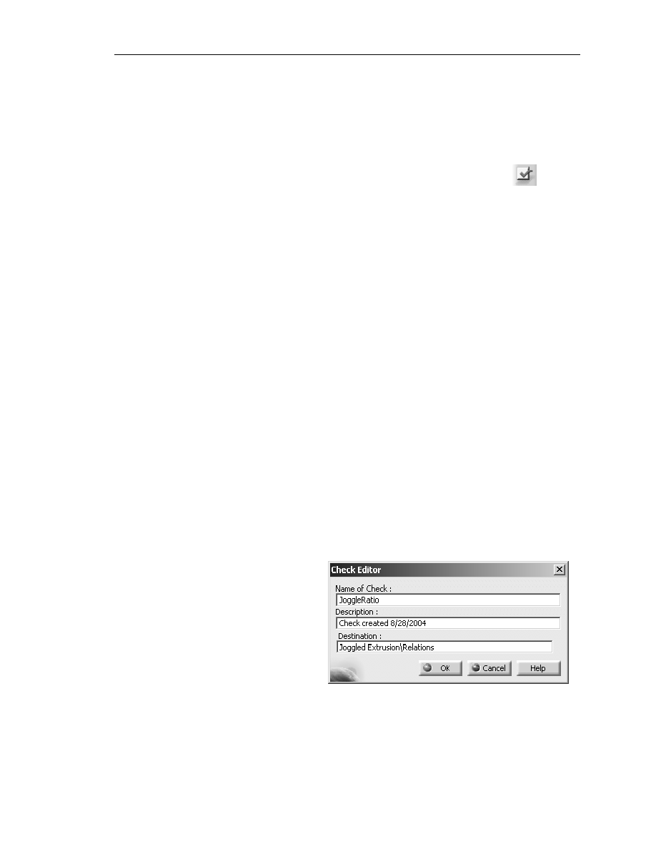
19.1
Double click on the Relations branch of the Specification Tree. This will
bring up the Knowledge Advisor work bench.
19.2
Select the Check tool.
This will bring up the
Check Editor window
as shown in Figure 1.27.
19.3
Label the check
“JoggleRatio.”
19.4
Select OK. This will
bring up the Check
Editor : JoggleRatio
Active window as
shown in Figure 1.28.
Copyrighted
Material
Copyrighted
Material
Copyrighted
Material
Copyrighted
Material
1.34
A
dvanced
C
ATIA
V5 W
orkbook
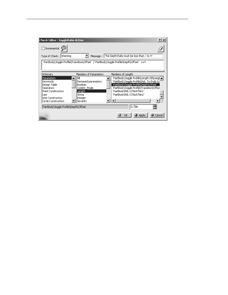
Figure 1.28
19.5
Select Warning as the Type of Check.
19.6
In the Message box, type “The Depth Ratio must be less than 1 to 4!”
19.7
Under Dictionary, select Parameters.
19.8
In the Members of Parameters box, select Length.
19.9
In the Members of Length box, double click on the ‘PartBody Joggle
Profile\Transition\Offset’ parameter. This will copy it to the input box
above it.
19.10
Type in the symbol for divide ( / ) after the inserted line. Reference Figure
1.28.
Copyrighted
Material
Copyrighted
Material
Copyrighted
Material
Copyrighted
Material
K
nowledgeware
1.35
Figure 1.29
19.11
In the Members of Length box, double click the ‘PartBody\Joggle
Profile\Depth\Offset’ parameter. This will copy it to the end of the line
you have been creating in the input box above it.
19.12
Type in >=4 following the ‘…\Depth\Offset’ parameter. Steps 19.9
through this step created a formula that tests the values the user enters
when running the JoggleDimensions.CATScript macro. The formula
needs to be the exact format as seen in Figure 1.28. If the Transition
value divided by the Depth value is >= 4, everything is ok. If the value is
not >=4, then a Warning window will appear on screen stating the
message you created in Step 19.6, “The Depth Ratio must be less then
1 to 4!”
19.13
Select the OK button. Notice that CATIA V5 adds a Check branch
labeled JoggleRatio on the Specification Tree under the Relations
branch. When the conditions of the check are met, the JoggleRatio
branch will show a Green light. When the conditions are not met, the
JoggleRatio branch will show a Red light.
19.14
If the values you enter for the JoggleDimensions.CATScript macro are
not >=4, the JoggleRatio warning window will appear as shown in Figure
1.29. In this particular Check the Joggled Extrusion will still be updated
even though it did not pass the check. The Type Of Check was a
Warning. CATIA V5 let you know that it did not pass the check.

Copyrighted
Material
Copyrighted
Material
Copyrighted
Material
Copyrighted
Material
1.36
A
dvanced
C
ATIA
V5 W
orkbook
Even though this is a simplified application of the CATIA V5 Check tool, it is very
useful. It also gives you a glimpse of how powerful this tool can be. This step
should give you enough information to start building on more complex checks.
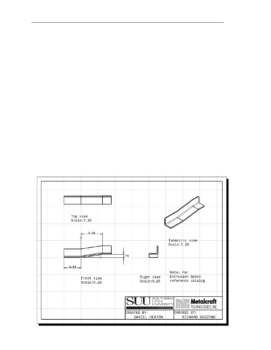
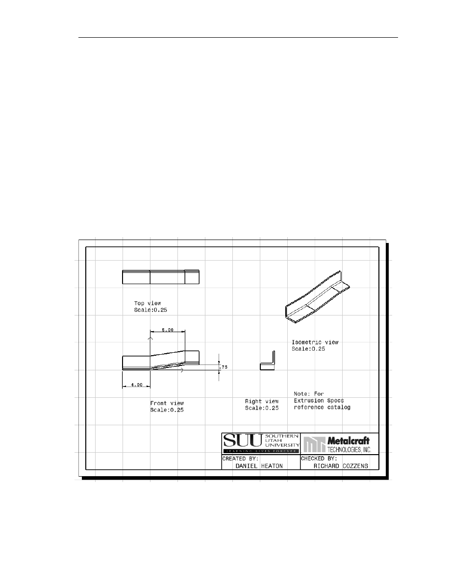
20. Practical Application…
Creating an Up-to-Date Production Drawing Automatically
So far this lesson has shown you some powerful Knowledgeware tools. This is the
step that brings it all together. The objective from the beginning was to develop an
automated process of creating Detailed Production Drawings. To accomplish this,
complete the following steps.
NOTE: This lesson assumes that you know how to use the CATIA V5 Drafting
work bench.
20.1
Using the Drafting work bench, create a basic Production Drawing of the
Joggled Extrusion. Use the Orthographic views and one Isometric view
as shown in Figure 1.30.
20.2
Dimension the characteristics of the Joggled Extrusion. The
characteristics of the joggle are:
20.2.1
End of part to start of joggle.
20.2.2
Joggle transition.
20.2.3
Joggle depth.
There is no need to dimension the characteristics of the extrusion because the
Tierany Metals Catalog contains all of the extrusion dimensions. The Joggle
Operator determines the joggle characteristics, not the extrusion characteristics. The
production drawing only need contain the information that is pertinent to the process
it is designed for. The dimensions required are shown in Figure 1.30.
20.3
Add a title block and production notes as required, similar to what is shown
in Figure 1.30.
20.4
Save the Production Drawing as “Joggled Extrusion.CATDrawing.”
20.5
Print and/or plot as required.
Copyrighted
Material
Copyrighted
Material
Copyrighted
Material
Copyrighted
Material
K
nowledgeware
1.37
Figure 1.30
20.6
Run the JoggleDimensions.CATScript. Change the joggle dimensions as
shown:
20.6.1
Depth = .40″
20.6.2
Transition = 3″
20.6.3
Dist. To Endp. = 2″
20.7
Bring up the Joggled Extrusion.CATDrawing. Update the drawing using
the Update tool. Notice the view and dimensions automatically update to
the newly selected extrusion and joggle dimensions.
This is where CATIA V5 Knowledgeware really saves time. The user can continue
to automatically create production drawings for unique Joggled Extrusion Parts.

Copyrighted
Material
Copyrighted
Material
Copyrighted
Material
Copyrighted
Material
1.38
A
dvanced
C
ATIA
V5 W
orkbook
Lesson 1 Summary
The Knowledgeware product is made up of the following work benches: Knowledge
Advisor, Knowledge Expert, Product Engineering Optimizer, Product Knowledge
Template, Product Function Optimization and Product Functional Definition. This
lesson used a small portion of the tools contained in each individual work bench. Even
though only a few tools were used, a great deal of time was saved. The remaining tools
offer similar opportunities for significant time saving. This lesson has supplied you with
enough information to get you started. Your challenge is to find ways to implement them
into your business and processes.

Copyrighted
Material
Copyrighted
Material
Copyrighted
Material
Copyrighted
Material
K
nowledgeware
1.39
Lesson 1 Review
After completing this lesson, you should be able to answer the questions and explain the
concepts listed below.
1.
The name of a constraint can be changed by double clicking on:
A.
The constraint symbol in the Specification Tree.
B.
The geometry being constrained.
C.
The actual constraint in the sketch.
D.
Both A and C.
2.
Where do you turn on the Parameters and Relations so that they appear in
the Specification Tree?
A.
Tools, Options, General, Parameters and Measures.
B.
Start, Infrastructure, Product Structure.
C.
Tools, Customize, Knowledge Advisor.
D.
Tools, Options, Display, Tree Appearance.
3.
How can associations be created between the column headings in an Excel
table, and CATIA parameters?
A.
By giving the column headings the same name as CATIA gives to the
desired parameter and allowing CATIA to automatically associate the two.
B.
By going into the Associations tab of the Extrusion Table and clicking
on the Create Parameters button.
C.
Manually select the column heading under the Associations tab then also
highlighting the desired parameter in the Parameters box and click the
Associate button.
D.
Both A and B.
E.
Both B and C.
F.
You can’t; it is impossible unless you are a computer genius.

Copyrighted
Material
Copyrighted
Material
Copyrighted
Material
Copyrighted
Material
1.40
A
dvanced
C
ATIA
V5 W
orkbook
4.
How do you access an Extrusion Table that you have created in CATIA so
that you can change the configuration row?
A.
Click on the Extrusion Table icon in the bottom tool bar of any work
bench.
B.
Go into Knowledge Advisor and click on the Extrusion Table icon in the
bottom tool bar.
C.
Double click on the Extrusion Table symbol in the Specification Tree
which will take you directly into the table regardless of which work bench
you are currently in.
D.
Double click on the Extrusion Table symbol in the Specification Tree
which will first take you into the Knowledge Advisor work bench, if you
are not already there, then you must double click again on the symbol to
open the table.
E.
Press Ctrl + T.
5.
How do you edit an existing Extrusion Table to give it different values or
add new configuration rows?
A.
Open the spreadsheet outside of CATIA and make the changes, then save
them and close the file. When you open the table in CATIA, it will be
automatically updated for you.
B.
Make the changes directly to the Extrusion Table by highlighting the
rows to be changed and clicking the Edit button.
C.
Open the design table and click the Edit table button and then make the
changes to the spreadsheet that comes up then save the changes and close
the spreadsheet.
D.
Both A and C.
E.
Both B and C.
6.
What must be added to a macro name in order to access it externally or link it
to an icon?
A.
.CATPart
B.
.CATDrawing
C.
.CATKnowledge
D.
.CATScript
E.
.VBScript
F.
.com

Copyrighted
Material
Copyrighted
Material
Copyrighted
Material
Copyrighted
Material
K
nowledgeware
1.41
7.
(True/False) An icon can be added to a tool bar that can be used to activate a
macro that is stored either within the CATPart file or in an external file, as
long as it has the proper extension.
A.
True
B.
False
8.
Which work bench contains a tool that allows you to create a Check that will
monitor the parameter relations in the CATPart?
A.
Product Engineering Optimizer
B.
Generative Shape Design
C.
Generative Knowledge
D.
Assembly Design
E.
Knowledge Advisor
9.
Once a check has been created, CATIA indicates whether the part passes the
check by:
A.
Turning the part red or grey.
B.
Bringing up the information or warning box that you programmed into the
check.
C.
Making the part disappear.
D.
Not allowing you to make changes that do not pass the check.
E.
Highlighting a red or green light next to the check in the specification tree.
F.
Both A and B.
G.
Both B and E.
10.
(True/False) Each time you use the Knowledgeware functions to make
changes to a CATPart, you must create a new CATDrawing if you want to
show the dimension changes in a new production drawing.
A.
True
B.
False

Copyrighted
Material
Copyrighted
Material
Copyrighted
Material
Copyrighted
Material
1.42
A
dvanced
C
ATIA
V5 W
orkbook
Lesson 1 Practice Exercises
Complete the following practice exercises using the information and experienced gained
by completing this lesson.
1.
Create a new spreadsheet using the same format used in this lesson. Link the
spread sheet with the CATPart document. Update the drawing documents
with each new extrusion defined in the new spreadsheet. Save the
CATDrawing documents as “Lesson1 Exercise1 Part1.CATDrawing,”
“…Part 2.CATDrawing” and so on.
2.
Modify the JoggleRatio Check to 1 to 3. Save the document as “Lesson1
Exercise2 .CATDrawing.”
3.
Modify the Joggle Depth window prompt so it displays a warning about
entering a number that violates the depth ratio 1/3 used in Exercise 2. Save
the document as “Lesson 1 Exercise 3.”
4.
Modify the existing “L Extrusion” to a “T Extrusion.” Modify the sketches,
spreadsheet and other parameters as required. Save all related documents.
Wyszukiwarka
Podobne podstrony:
CATIA V5 Workbook
CATIA V5 tutorial advanced
CATIA V5 Training Basics
CATIA V5 kurs podstawowy
CATIA V5 Modelowanie PL
Catia v5 Structural Analysis For The Designer
catia v5 modelowanie kurs podstawowy LZIVC3JESPF2KJV3WU7KPG7Z742RKIM3LA77XXA
CATIA V5 Training Basics
Bewegungssimulation mit Catia V5
catia v5 machining brochure
Airbus Catia V5 Training Wireframe and Surface
TRAVELLER Advanced Workbook key
Advanced Polyphthalamide (PPA) Metal Replacement Trends
Advanced Mechanics in Robotic Systems (Springer 2011 Ed1)
advanced calculate perimeter worksheet
Clockwise Advanced Practice Key
więcej podobnych podstron