
AIRBUS UK
CATIA V5 Foundation Course
DMS42189
Page 1 of 17
Issue 1
ANS-UG0300112
Compiled by: Kevin Burke
Kevin Burke
Date: 16/Apr/2003
Approved by:
Date:
Authorised by:
Date:
AIRBUS UK Ltd. All rights reserved.
Foundation Course
Wireframe and
Surfacing Overview

AIRBUS UK
CATIA V5 Foundation Course
DMS42189
Page 2 of 17
Issue 1
ANS-UG0300112
Contents
Session 7 – An overview of Wireframe and Surfacing ...........3
An Introduction to Generative Shape Design ........................................................... 4
Accessing the Generative Shape Design Workbench ............................................... 5
Generative Shape Design Toolbars and Icons........................................................... 6
Extrude Surface ..................................................................................................... 7
Offset Surface........................................................................................................ 8
Loft Surface......................................................................................................... 10
Fill Surface .......................................................................................................... 12
Projection ............................................................................................................ 13
Split Surface ........................................................................................................ 14
Join Surface ......................................................................................................... 15
Extrapolate Surface ............................................................................................. 16
Intersection .......................................................................................................... 17

AIRBUS UK
CATIA V5 Foundation Course
DMS42189
Page 3 of 17
Issue 1
ANS-UG0300112
Session 7 – An overview of Wireframe
and Surfacing
On completion of this session the trainee will:
♦
Be able to access the Generative Shape Design Workbench.
♦
Be capable of creating Extruded Surfaces.
♦
Be able to create Offset Surfaces.
♦
Have a basic understanding of how to Loft a Surface.
♦
Be able to create a basic Fill Surface.
♦
Be able to Project elements onto Surfaces and Split them.
♦
Use the Join command to Join Surfaces together.
♦
Create an Extrapolated a Surface.
♦
Be able to Intersect Surfaces.
AIRBUS UK
CATIA V5 Foundation Course
DMS42189
Page 4 of 17
Issue 1
ANS-UG0300112
An Introduction to Generative Shape Design
There are various Workbenches within Catia where you can create both wireframe
and Surface type elements. The majority can be found under the Shape and
Mechanical Design Functions.
For the purpose of this overview into Wireframe and Surfacing we will be using the
Generative Shape Design Workbench.
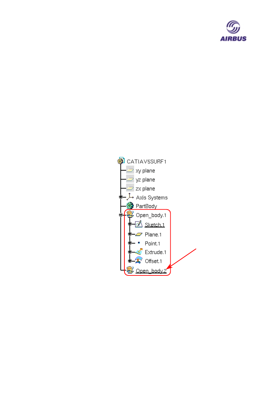
Geometry created using this and other surfacing workbenches is placed in an Open
Body node rather than a Partbody. An Open Body can contain both Wireframe and
Surface geometry but not Solids. As with Partbodies you can have multiple
Openbodies within a CATPart.
Sketches can be created in either a PartBody or an Open Body. You can move a
Sketch from an Open Body to a PartBody by selecting the Sketch node with MB1
and then using Cut and Paste from the Edit drop down menu or the MB3 contextual
menu to perform the move. You can also create copies of the Sketch by using Copy
and Paste.
As you create geometry it will automatically be attached to the currently active Open
Body which is identified by the node being underlined.
To add a new Open Body to the Specification Tree Select Open Body from the
Insert drop down menu when you are in one of the Surfacing Workbenches.
Currently
Active
Open Body
AIRBUS UK
CATIA V5 Foundation Course
DMS42189
Page 5 of 17
Issue 1
ANS-UG0300112
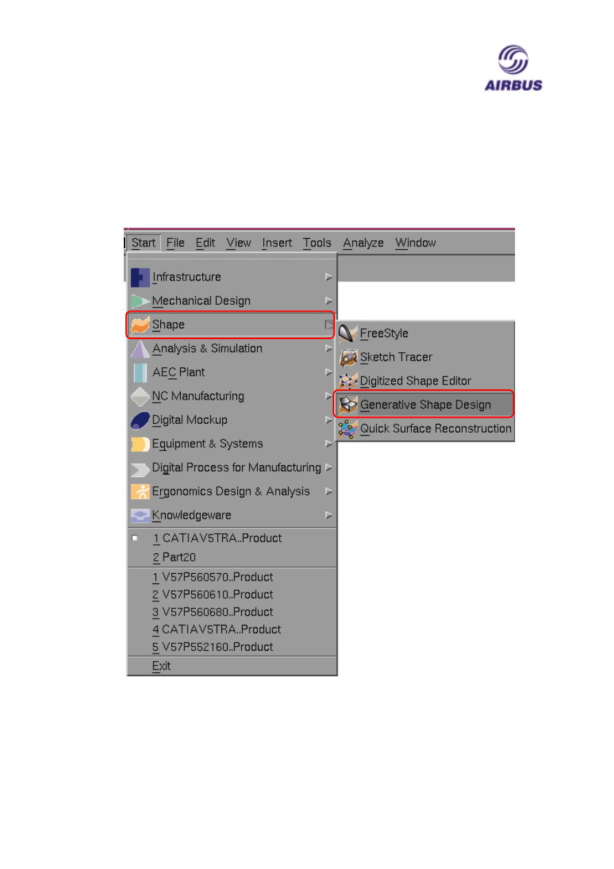
Accessing the Generative Shape Design Workbench
The Generative Shape Design Workbench can be accessed through the Shape
Function from the Start drop down menu.
AIRBUS UK
CATIA V5 Foundation Course
DMS42189
Page 6 of 17
Issue 1
ANS-UG0300112
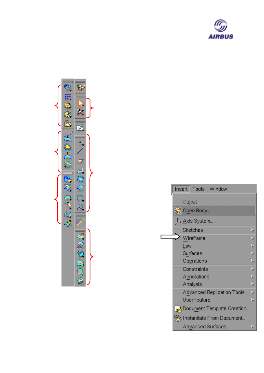
Generative Shape Design Toolbars and Icons
The two Toolbars that we will be
concerned with during this session are: -
1. The Surfaces toolbar – this allows
you to create surfaces
2. The Operations toolbar – allows you
to manipulate Surfaces.
Replication
Advance
Surfaces
Operations
Wireframe
Surfaces
Laws
Sketcher
Workbench Icon
Selection
The Generative
Shape Design
commands can
also be access
through the
Insert drop down
menu
AIRBUS UK
CATIA V5 Foundation Course
DMS42189
Page 7 of 17
Issue 1
ANS-UG0300112
Extrude Surface
The first command that we will cover is Extrude Surface, which can be found on the
Surfaces Toolbar.
This command will allow you to Extrude a selected profile to form a single or
group of joined Surfaces.
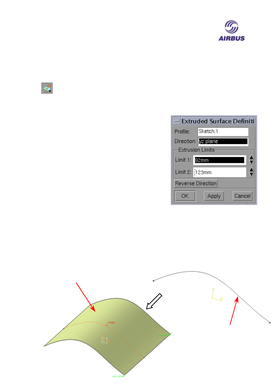
Select the icon to display an Extrude Surface Definition panel.
The Profile field displays the name of the element or
Sketch that you have selected as the Profile to be
extruded.
The Direction lists the element that is used to define
the direction of the extrusion. By default when a Sketch
is selected then a plane normal to the Sketch plane is
used. By highlighting this field you can select your
direction element i.e. a Line or Plane.
The Extrusion Limits portion of the panel control the
overall length of the extrusion by using the Limit 1 and
2 fields to enter distances which are applied to either
side of the profile plane. You can also Grab the LIM1
and LIM2 using MB1 to control the length of the
Limits.
The Reverse Direction button reverses the direction of the limits.
After selecting the profile to be extruded, a direction element if desired and distance
for the limit you have to click OK to complete the command.
Selected
Profile
Resulting
Surface
AIRBUS UK
CATIA V5 Foundation Course
DMS42189
Page 8 of 17
Issue 1
ANS-UG0300112
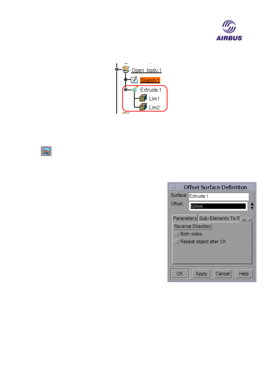
An Extrude node is attached to the Specification in the currently active Open Body.
Offset Surface
This command allows you to create an Offset Surface from an existing
Surface, and can be found on the Surfaces Toolbar.
Select the icon followed by a Surface to offset from. An Offset Surface Definition
panel will appear with the following options: -
The Surface field displays the name of the Surface
you selected to offset from.
The Offset field allows you to enter a distance for the
offset. You can also Grab the Green Offset marker to
control the distance
The Parameters tab allows you to Reverse the
Direction of the Offset, you can also use the orange
arrow to reverse direction. If you check the Both sides
check box then the offset is created either side of the
selected Surface. Selecting Repeat object after OK
check box will allow you to reuse the command to
create multiple offsets using the Offset value as a Step
size.
The Sub-Elements to Remove tab allows you to run analysis on the intended offset
containing more than one surface. Errors can be detected and Sub-Surfaces or
elements can be removed from the Offset.
AIRBUS UK
CATIA V5 Foundation Course
DMS42189
Page 9 of 17
Issue 1
ANS-UG0300112
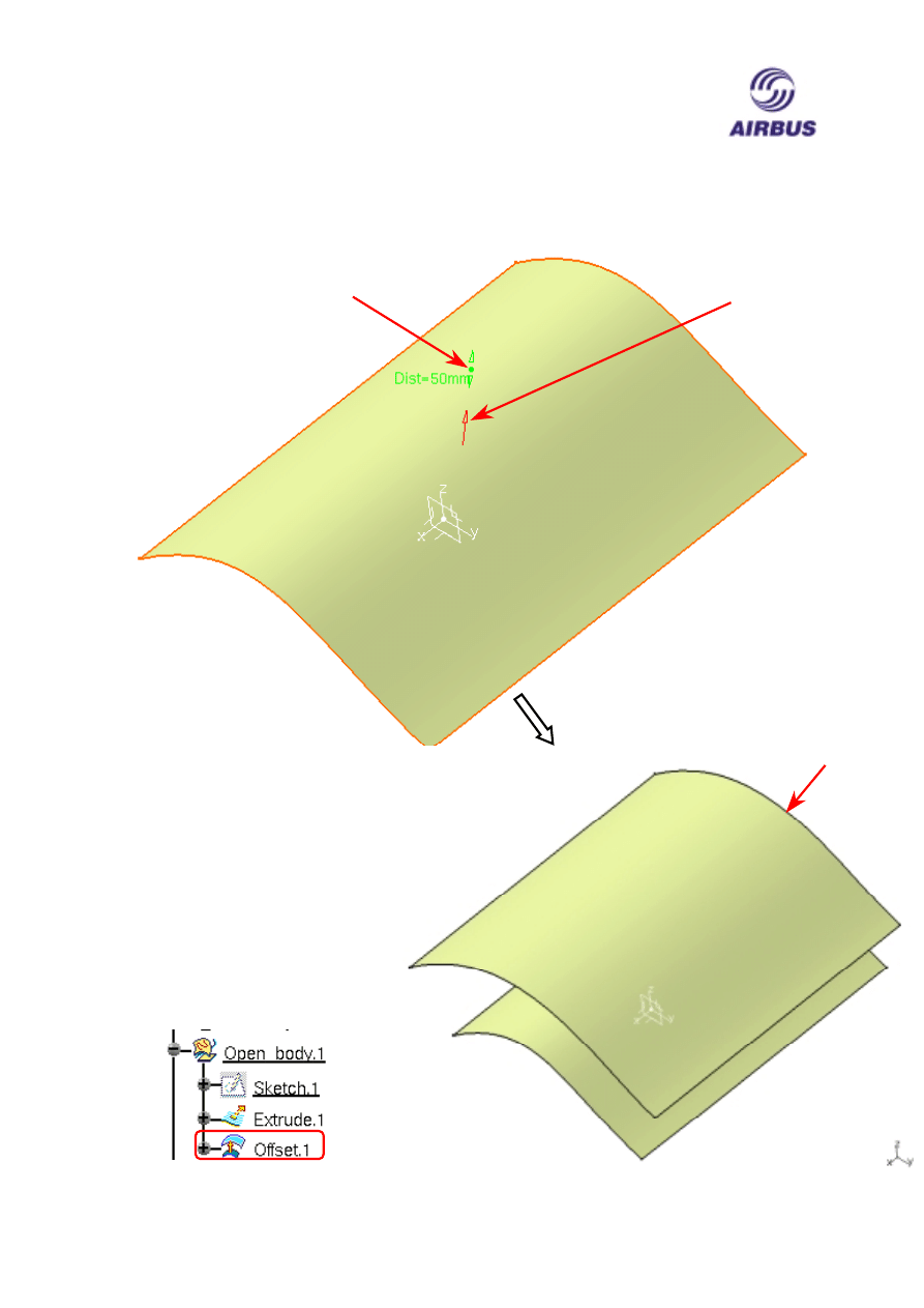
In the following example an Extruded Surface is offset by 50mm. The resulting offset
Surface is dependent upon the Extrude, therefore, if you delete the Extruded Surface
then the offset will be deleted as well.
Reverse
Direction
Arrow
Offset
Marker
Resulting
Offset
Surface
After clicking OK the
Surface is create and
Offset node is added
to the currently active
Open Body
AIRBUS UK
CATIA V5 Foundation Course
DMS42189
Page 10 of 17
Issue 1
ANS-UG0300112
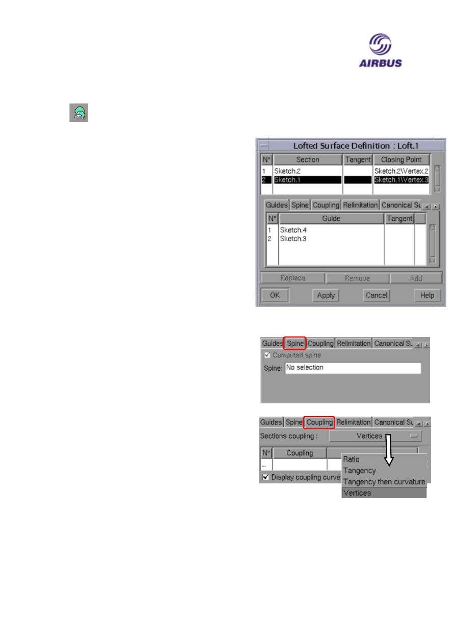
Loft Surface
Allows you to create a Lofted Surface through a series of selected Profiles
similar to the Loft command in the Part Design Workbench.
Select the icon which located on the Surfaces
Toolbar to display a Loft Surface Definition
panel.
The top portion of the panel displays which
profiles have been selected and the order that
they have been selected.
Note: At least two non-intersecting profiles
must be selected.
The bottom portion as five tabs: -
The Guides tab lists the selected guides. The
purpose of guides is to control how the Loft
cross section is controlled between the profiles
The Spine tab lists any Spine that is used. When a
Spine is use, the transition shape between profile
is kept normal to the Spine curve. By default if no
spine is selected then Catia will compute one
based on the profiles and their orientation to each.
Both the spine and guides are optional.
The Coupling tab allows you select how the
transition is mapped between profile. The are
four Section coupling options: -
Ratio maps the profiles together by a curvature
ratio.
Tangency maps the profiles together by their tangent discontinuity
points. If there are not the same number of points in each curve then this option will
cause the Loft to fail.
Tangency then curvature maps the profiles together by their curvature discontinuity
points. As with tangency if there are not the same number of points in each curve then
this option will cause the Loft to fail.
AIRBUS UK
CATIA V5 Foundation Course
DMS42189
Page 11 of 17
Issue 1
ANS-UG0300112
Vertices maps the vertices of the profiles together. Again there must be the same
number vertices in each profile for the Loft command to succeed.
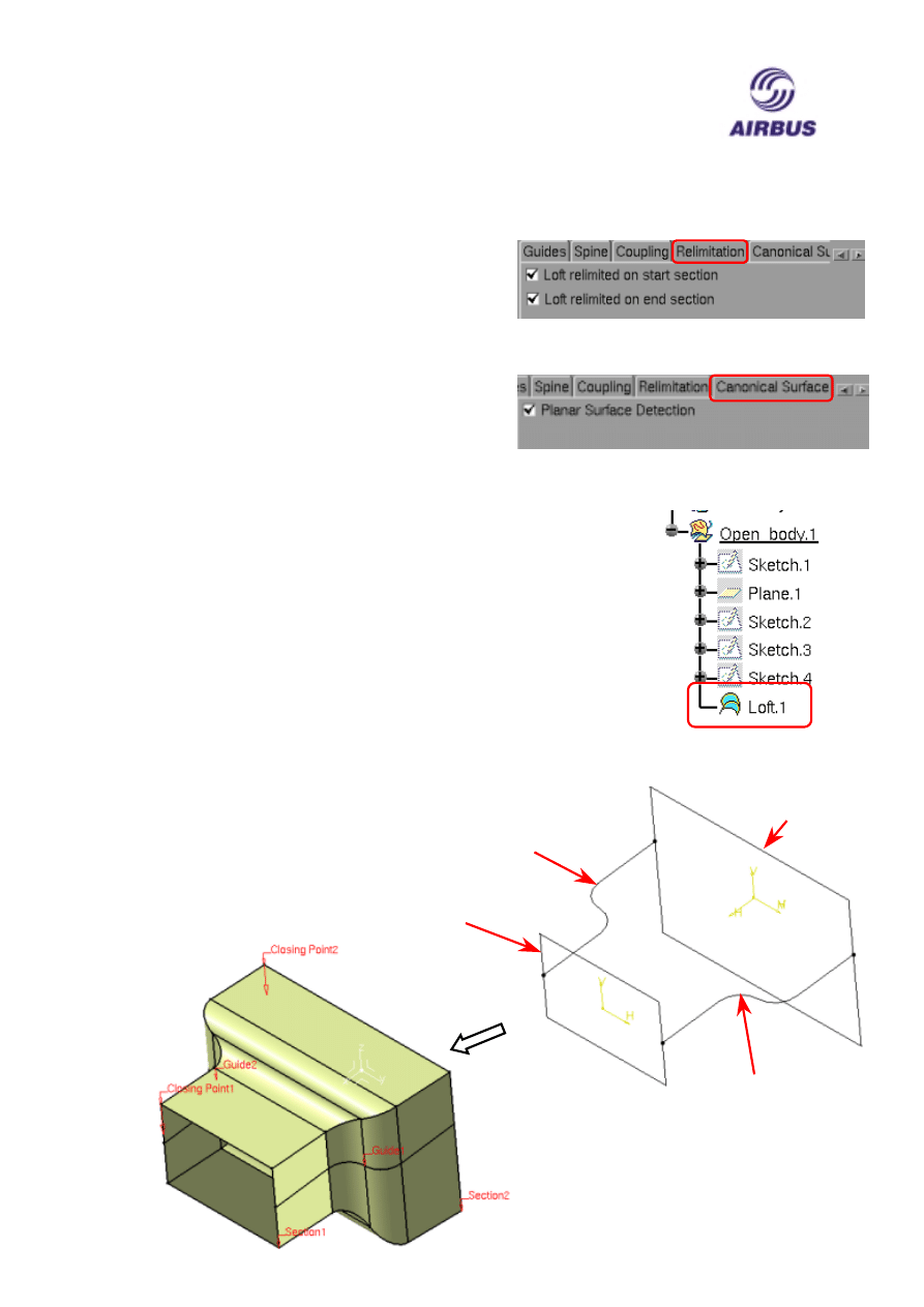
The Relimitation tab allows you to re-limit the
start and end sections of the Loft. The two
options are to limit the loft to the first profile
and the last profile. If either of these options is
not selected then the Spline curve or the Guide
curves control the relimit.
The final tab on the panel is the Conical
Surface tab allows create Conical Surfaces
The same rules apply to Lofting Surface as with creating a Lofted
Solid i.e. the Closing Points must by aligned to prevent twist of the
loft between Profiles.
After you have selected at least two Profiles and the desired option
click OK to create the Loft. A Loft node is then added to the
Specification Tree in the currently active Open Body.
In the following example a lofted surface is created using two
Sketches containing multi-element Profiles. The cross-sectional
shape of the loft is controlled by two Guide Profiles contained
within two different Sketches. The Coupling point has been set to Vertices.
Profile 1
Guide
Profile 2
Profile 2
Guide
Profile 1
AIRBUS UK
CATIA V5 Foundation Course
DMS42189
Page 12 of 17
Issue 1
ANS-UG0300112
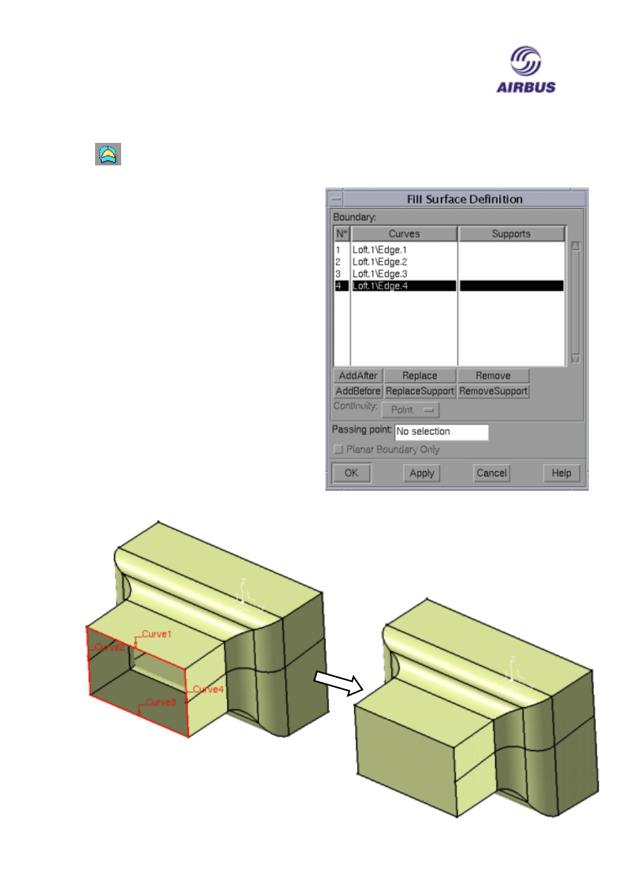
Fill Surface
Located on the Surfaces Toolbar this command you can create a Surface to fill
a gap between surfaces.
Select the icon to display a Fill Surface
Definition panel.
The Boundary portion of the panel lists the
edge boundary of the Surface that you have
selected to form the Fill.
Note: You must select the edges in a
logical sequence with no gaps otherwise
the fill will fail.
You can apply Tangency to the Fill
Surface by selecting the Support Surfaces
as well as the Edge curves and Select
Continuity Tangent.
After selecting the required Edges and
Supports, if required, click OK to create
the Fill.
A Standard Fill with just four
Edges selected with no Support
Surfaces selected.
AIRBUS UK
CATIA V5 Foundation Course
DMS42189
Page 13 of 17
Issue 1
ANS-UG0300112
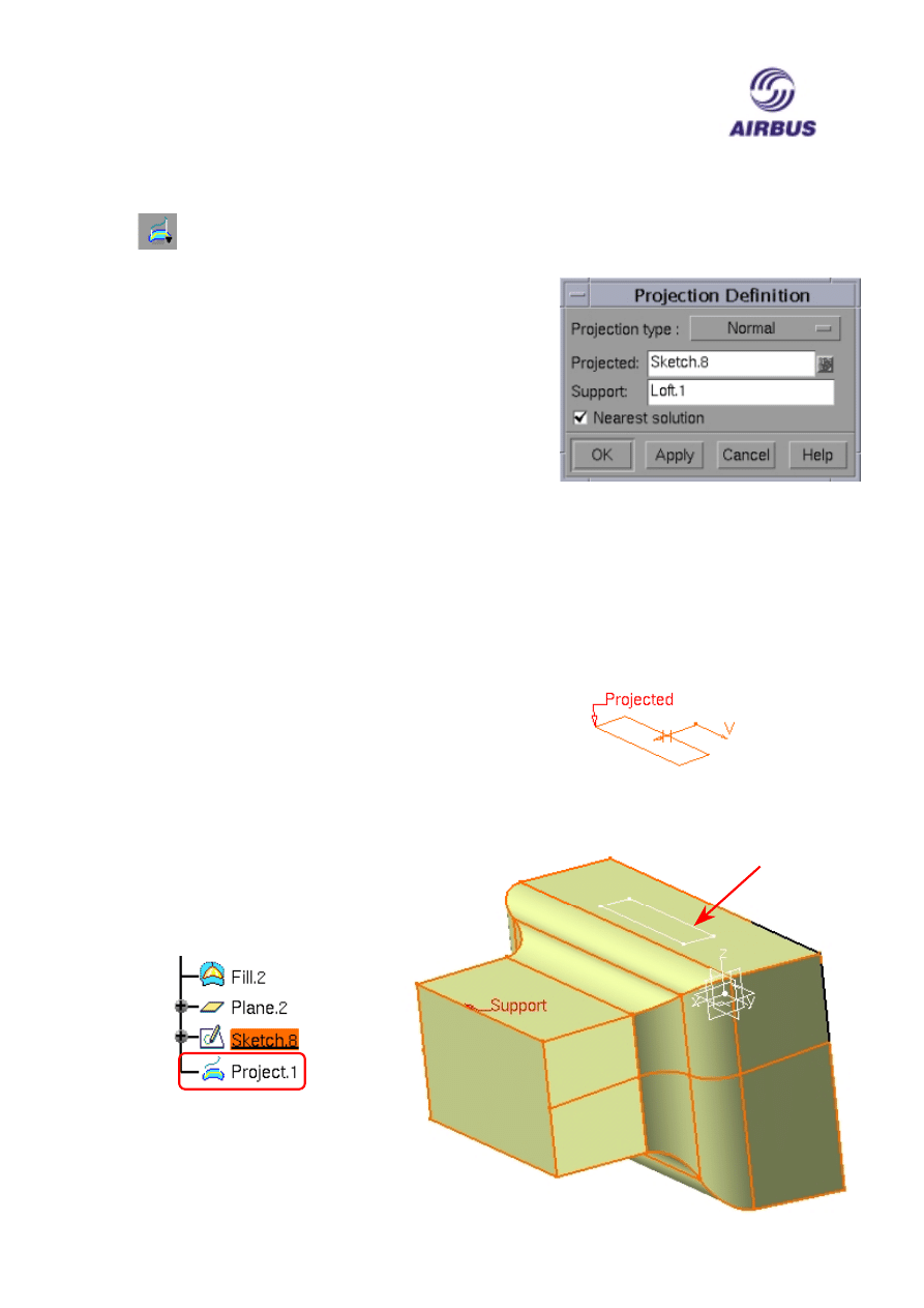
Projection
This allows you to Project Elements on to a Surface. This icon can be found on
the Wireframe Toolbar.
Select the icon to display a Projection Definition
panel.
You must select an element or Sketch to be projected,
which will then be displayed in the Projected field.
You then have to select a Surface to project the
element to be projected onto. This is displayed in the
Support field.
The Nearest solution checkbox if selected will limit the projection to the first
element found on the Support.
Finally the Projection type button allows you to specify whether the projection is
Normal to the Support or Along a Direction which you must specify by selecting a
Line or a Plane.
In the following example a sketch containing a rectangular Profile is Projected onto
the nearest element of a Loft.
After selecting the required
elements to Project and use as
the Support click OK to create
the Projected elements and a
Project node is attached to the
Specification Tree under the
currently active Open Body.
Resulting
Project
Elements
AIRBUS UK
CATIA V5 Foundation Course
DMS42189
Page 14 of 17
Issue 1
ANS-UG0300112
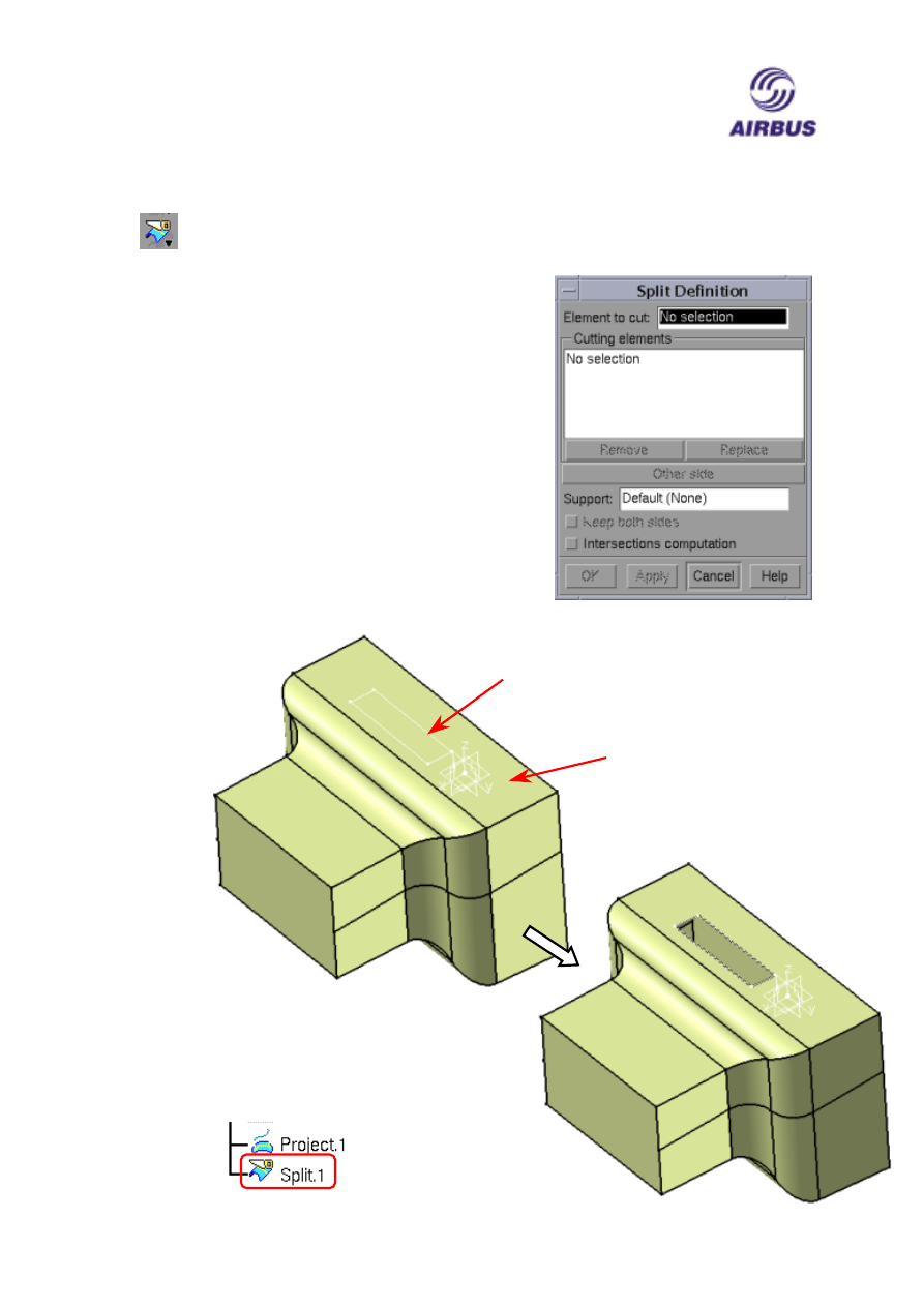
Split Surface
This icon is located on the Operations Toolbar and can be used to Split
Surface based features.
Select the icon to display a Split Definition panel.
You have to select an element to Split, which will
then be listed in the Element to cut field. This is to
be followed by the element(s) that are to be used as
Splitting elements which can be a group of separate
elements or a single profile contained in Sketch and
these are listed in the Cutting elements window.
The Other side button reverses which portion of the
Split is kept.
There also the option to keep both portions of the
split by selecting the Keep both sides checkbox. In
this case when you click OK to create the Split then
two Split operations appear in the Specification Tree.
Splitting
Profile
Surface to
be Split
Resulting Split
as remove a
portion of the
Surface
After clicking OK a Split
node is attached to the
Specification Tree under
the currently active Open
Body
AIRBUS UK
CATIA V5 Foundation Course
DMS42189
Page 15 of 17
Issue 1
ANS-UG0300112
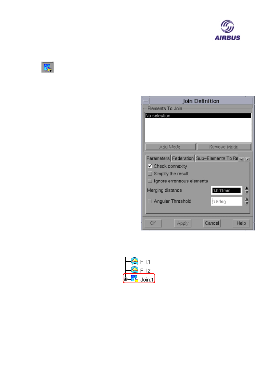
Join Surface
The Join Surface command allows you to join Surface based features or
Curves together. When selecting Surfaces if the Join produces an enclosed
volume then it can be converted into a Solid feature within the Part Design
Workbench by using the Close Surface command. The icon for this command is
located on the Operations Toolbar.
After selecting the icon a Join Definition
panel will appear.
The Element to Join portion list the
Surfaces or Curves that you have selected
to Join.
The Parameters tab allows you to control
the how the selected elements are joined.
The Federation tab allows you to group
selected elements together.
The Sub-Elements to Remove allows you
to remove Sub-Element from the Join list
i.e. elements from Sub-Element created by
a previous Join command.
To complete this command select the
elements to be joined and any desired
options followed by clicking OK to create
the Join. A Join Node will be added to the Specification Tree under the currently
active Open Body.
AIRBUS UK
CATIA V5 Foundation Course
DMS42189
Page 16 of 17
Issue 1
ANS-UG0300112
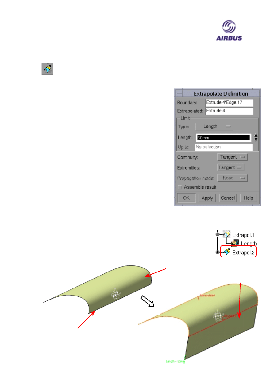
Extrapolate Surface
With this command you can create an extension to an existing Surface. The
Extrapolate icon can be located on the Operations Toolbar.
After selecting the icon a Extrapolate Definition panel will appear with the following
options: -
The Boundary field lists the element that you have
selected as the edge of the existing surface to be
extended.
The Extrapolated field lists the existing Surface that you
have selected to extend.
The Limit portion of the panel controls whether you
extend the Surface by Length or Up to Element via the
Type button. If Length type is selected then you can
enter the value in the Length field and if Up to Element
is selected then you must select an element to control the
extension which will then be displayed in the Up to field.
The Continuity, Extremities and Propagation mode
buttons allow you to specify whether the extension is
Tangent or Curvature continuous.
The Assemble result checkbox if selected joins the extension to a copy of the original
Surface.
After selecting the Boundary, the Surface to be Extrapolated, Limit type
and the extension method click OK to create the Extrapolation. An
Extrapolate node is then attached to the Specification Tree under the
currently active node.
Surface to be
Extrapolated
Selected
Boundary
Result
extended
Surface
AIRBUS UK
CATIA V5 Foundation Course
DMS42189
Page 17 of 17
Issue 1
ANS-UG0300112
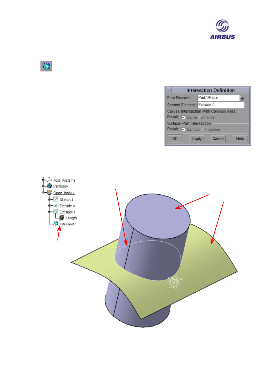
Intersection
The final command covered in this session is the Intersection command
which is use to intersect two elements together to create an intersect element.
The icon for this command can be found on the Wireframe Toolbar.
Select the icon to display the Intersection Definition
panel.
The First and Second Element field lists the elements
you have selected to Intersect.
The other options are not selectable.
After selecting the elements to be intersected click OK
to create the intersection element. This will also result
in an Intersect node being added to the Specification Tree.
Two elements
to be
Intersected.
The Intersect
node
The resulting
Intersect
element
Wyszukiwarka
Podobne podstrony:
CATIA V5 Training Basics
CATIA V5 Training Basics
CATIA V5 kurs podstawowy
CATIA V5 Modelowanie PL
7 77 93 Heat and Surface Treatment of Hot Works for Optimum Performance
Catia v5 Structural Analysis For The Designer
catia v5 modelowanie kurs podstawowy LZIVC3JESPF2KJV3WU7KPG7Z742RKIM3LA77XXA
Mind and Memory Training, MIND AND MEMORY TRAINING
CATIA V5 tutorial advanced
CATIA V5 Workbook
Corrosion behavior and surface characterization of titanium
Electrochemical and surface
Concentration, pH and Surface charge Effects on
Bewegungssimulation mit Catia V5
Advanced Catia v5 Workbook
catia v5 machining brochure
więcej podobnych podstron