
ENVI Tutorial:
Orthorectifying Imagery
using Rational Polynomial
Coefficients (RPCs)
Orthorectifying Using Rational Polynomial Coefficients (RPCs)
Introduction to RPC Orthorectification
Examine the Orthorectification Results
1

Orthorectifying Using Rational Polynomial
Coefficients (RPCs)
This tutorial demonstrates ENVI's orthorectification tools that use rational polynomial coefficients
(RPCs). You will orthorectify an IKONOS image of La Jolla, California, USA, courtesy of Space
Imaging. You will then compare the orthorectified image to the uncorrected image and examine the
differences.
Files Used in This Tutorial
ENVI Resource DVD: Data\ortho
File
Description
conus_usgs.dem
USGS digital elevation model (DEM) for the area of the
IKONOS image
po_101515_metadata.txt
Metadata file for the IKONOS image
po_101515_pan_0000000_rpc.txt
Text file containing RPCs
po_101515_pan_0000000.tfw
TIFF world file containing initial georeferencing information
po_101515_pan_0000000.tif (.hdr)
IKONOS image data in TIFF format
2
ENVI Tutorial: Orthorectifying Imagery using Rational Polynomial Coef-
ficients (RPCs)

ENVI Tutorial: Orthorectifying Imagery using Rational Polynomial Coef-
ficients (RPCs)
Introduction to RPC Orthorectification
Orthorectification is a process of making the geometry of an image planimetric, or map-accurate, by
modeling the nature and magnitude of geometric distortions in the imagery. These distortions are caused
by topography, camera geometry, and sensor-related errors. Orthorectification is a logical step when
precise positional accuracy and uniform scale are required throughout an image. After orthorectifying an
image, you can measure or precisely locate features in the image, collect information for a GIS, or
combine the image with other orthorectified images for sophisticated analyses.
ENVI's orthorectification tools rectify data from specific pushbroom sensors (currently ASTER,
CARTOSAT-1, FORMOSAT-2, GeoEye-1, IKONOS, OrbView-3, QuickBird, RapidEye, SPOT, and
WorldView-1), using an RPC model. Data from each of these sensors typically include an ancillary RPC
file generated from ephemeris data, which ENVI uses to perform the orthorectification.
The following are required input for RPC orthorectification:
l
The image to rectify
l
RPC model (not required for SPOT data)
l
Elevation information
l
Offset between mean sea level and the gravitational potential surface (known as the geoid), so the
elevation can be correctly interpreted
l
If approximate geolocation information is not available for the source image, the rough location of
the image on the earth’s surface must be computed to provide a location base needed for the RPC
transformation.
The input image must be linked to the RPC coefficients contained in an ancillary text file. These
coefficients are required for the rational function expansion to convert ground coordinates into sensor
coordinates. In the case of opening an IKONOS image, which you will use for the following exercise,
ENVI searches for an RPC filename consisting of the root name of the source image plus _rpc.txt.
3
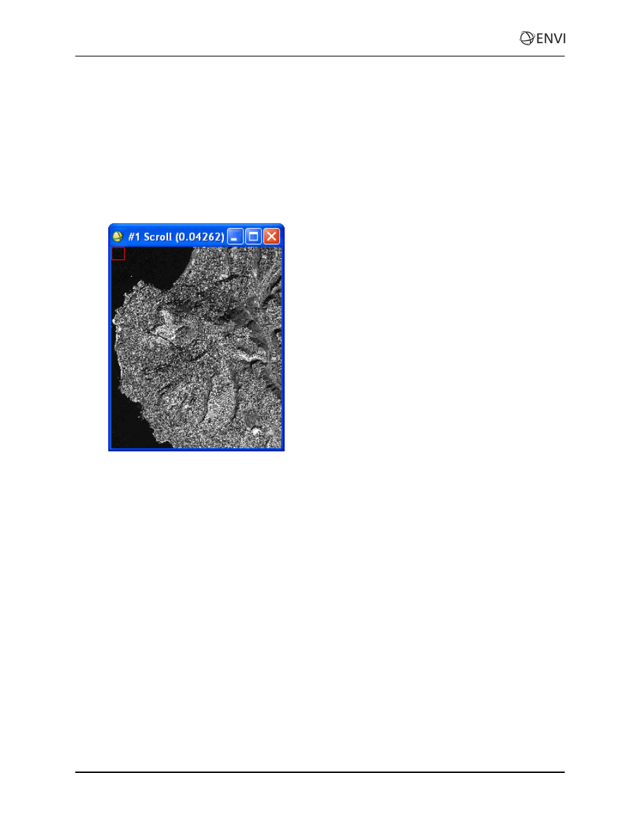
View Images
1. From the ENVI main menu bar, select File > Open Image File. A file selection dialog appears.
2. Navigate to Data\ortho and select po_101515_pan_0000000.tif. Click Open.
3. In the Available Bands List, select the Gray Scale radio button, select Band 1, and click Load
Band. Although the image has map information associated with it, orthorectification is still
required since the coordinates reported for any given point in the image are likely to have
significant positional inaccuracy.
4. A DEM is optional input, but it enhances the accuracy of the orthorectification. From the main
ENVI menu bar, select File > Open External File > Digital Elevation > USGS DEM.
5. Select conus_usgs.dem and click Open. A USGS DEM Input Parameters dialog appears.
6. Enter ortho_dem.dat for the output filename and click OK.
7. In the Available Bands List, click Display #1 and select New Display.
8. In the Available Bands List, select DEM Image and click Load Band.
The elevation for this area ranges from sea level to 245 m. This significant topographic variation is sure
to introduce geometric inaccuracies into the IKONOS image. The DEM and the IKONOS image do not
have the same map projection or pixel size. However, you do not have to reproject or resample the two
images; ENVI’s orthorectification tool accounts for their differences.
4
ENVI Tutorial: Orthorectifying Imagery using Rational Polynomial Coef-
ficients (RPCs)

ENVI Tutorial: Orthorectifying Imagery using Rational Polynomial Coef-
ficients (RPCs)
Run the Orthorectification
1. From the ENVI main menu bar, select Map > Orthorectification > IKONOS > Orthorectify
IKONOS. A file selection dialog appears.
2. Select po_101515_pan_0000000.tif and click OK. An Orthorectification Parameters
dialog appears.
3. Image Resampling is the method for determining pixel values in the IKONOS image during the
orientation. The default method is Bilinear, which provides moderately smooth results. The Cubic
Convolution option provides smoother results, while the Nearest Neighbor option does change the
original pixel values. The Nearest Neighbor option leads to a relatively choppy appearance, but it
is the only valid option if you intend to perform analyses on the orthorectified image. For this
tutorial, select Bilinear.
4. Background refers to the value assigned to the border pixels in the orthorectified image. Leave the
value at 0.
5. Input Height specifies whether a DEM or a fixed elevation value will be used for the entire
image. Because you have a DEM (the more accurate option), leave the DEM option selected.
6. Click Select DEM. A Select Input DEM Band dialog appears.
7. Select DEM Image under ortho_dem.dat and click OK.
8. DEM Resampling is the method used to determine pixel values for an internally calculated
version of the DEM image with the same orientation and pixel size as the IKONOS image.
Again, use the default Bilinear method.
9. Geoid offset is the height of the geoid above mean sea level in the geographic area covered by the
image. Most DEM images provide information about the elevation above mean sea level for each
pixel. Orthorectification, however, requires information about the height above the ellipsoid for
each pixel. To convert from the DEM mean sea level values to height above the ellipsoid, you
must add the geoid height to the DEM.
Enter a Geoid offset value of -35. This means the ellipsoid is about 35 m above mean sea level in
this area. Many institutions that perform photogrammetry have their own software for determining
geoid heights, or you can obtain software from NOAA, the National Geospatial Intelligence
Agency (NGA), USGS, or other sources
See the following URL for a geoid height calculator:
http://www.ngs.noaa.gov/cgi-bin/GEOID_
.
10. The right side of the dialog has parameters related to the extent and pixel size of the output image.
The default values are calculated from the georeferencing information in the original IKONOS
image. These values are appropriate for this example. You could also optionally change the
projection for the output orthorectified image by clicking Change Proj.
11. Enter ikonos_ortho.dat in the Orthorectified Image Filename field.
12. Click OK to begin the orthorectification process, which can take several minutes. After
processing is complete, the orthorectified image is added to the Available Bands List.
5
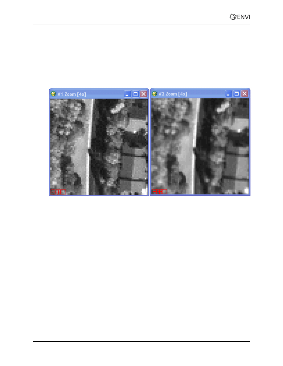
Examine the Orthorectification Results
1. Display the orthorectified image in Display #2, which currently contains the DEM image.
2. Compare the original IKONOS image to the orthorectified image by selecting Tools > Link >
Link Displays from a Display group menu bar and clicking OK in the Link Displays dialog.
3. Click inside an Image window to toggle between the two images. Notice the subtle difference in
geometry, especially in the upper-right corner of the two images:
4. When you are finished, select File > Exit from the ENVI main menu bar.
6
ENVI Tutorial: Orthorectifying Imagery using Rational Polynomial Coef-
ficients (RPCs)
Document Outline
Wyszukiwarka
Podobne podstrony:
Orthorect RPC
40 RPC Orthorectification
Zarz[1] finan przeds 11 analiza wskaz
11 Siłowniki
11 BIOCHEMIA horyzontalny transfer genów
PKM NOWY W T II 11
wyklad 11
R1 11
CALC1 L 11 12 Differenial Equations
Prezentacje, Spostrzeganie ludzi 27 11
zaaw wyk ad5a 11 12
budzet ue 11 12
EP(11)
W 11 Leki działające pobudzająco na ośrodkowy układ
Zawal serca 20 11 2011
11 Resusc 2id 12604 ppt
11 pomiay dlugosci tasma
więcej podobnych podstron