
Novel Process for Recycling Waste Plastics To Fuel Gas Using a
Moving-Bed Reactor
Yoichi Kodera* and Yumiko Ishihara
National Institute of AdVanced Industrial Science & Technology (AIST), 16-1 Onogawa, Tsukuba,
Ibaraki 305-8569, Japan
Takeshi Kuroki
Polymer Decomposition Laboratory, Inc., 2-12-7 Aoshima, Miyazaki City, Miyazaki 889-2162, Japan
ReceiVed August 18, 2005. ReVised Manuscript ReceiVed NoVember 6, 2005
The conventional pyrolysis of waste plastics, carried out in a tank reactor or kiln, yields fuel oil with a wide
boiling range. To improve the economic process of feedstock recycling of waste plastics, a new thermal process
for fuel-gas production is proposed. Considering the role of sand as an effective heating medium and by using
a reactor structure for suitably controlling the reaction temperature and reaction time, a new type of reactor
equipped with a screw conveyor has been developed; this reactor is termed the moving-bed reactor. The
formation of gaseous hydrocarbons was achieved at 82 wt % (pyrolysis) and 94 wt % (catalysis) in the operations
research of the new process using polypropylene as feed.
1. Introduction
The production of oil from waste plastics has been expected
to be an effective solution for landfill overflow and resource
limitations. Despite many R&D projects over the last three
decades, the recycling of waste plastics in oil production
processes encompasses only a negligible amount of all the waste
plastics generated in Japan. The economic disadvantages of oil
production processes result from technical problems such as low
treatment capacity depending on the type of reactor,
1
high energy
consumption, and a low quality of the oil products.
The produced oil is distributed to end users, typically as a
cheaper substitute for heavy oil. It has limited uses. For example,
it is used in industrial boilers, burners, and power generators.
On the other hand, in Japan, fuel gas is two to three times more
expensive than fuel oil and has wider applications. For example,
it can be used in conventional gas burners for domestic and
industrial purposes, liquid-gas-powered cars, and gas cogen-
eration systems; it is also accompanied by a lower emission of
toxic substances.
If fuel gas can be obtained as a major product from waste
plastics, it can be used as a new energy source for many factories
and waste management facilities. Fuel gas can also be a new
feedstock recycling process for waste plastics. In contrast to
oil production facilities, the facility for this process does not
require a distillation process and storage tanks for each distillate.
The aim of this research project is to develop a process for fuel-
gas production that will be a profitable business for the treatment
of waste plastics even on a small scale of about 2-8 tons/day,
which is the typical scale of waste plastics dealt with by waste
management facilities and manufacturing companies in Japan.
2. Technical Background of Fuel-Gas Production
To our knowledge, there is no economic process for fuel gas
production from waste plastics. Upon pyrolysis of polyolefins
such as polypropylene and polyethylene in a tank reactor, it is
not possible to control the residence time of the feed resulting
in the formation of liquid products and small amounts of gaseous
products with wide boiling ranges. Increasing the reactor
temperature often results in the promotion of the distillation of
waxy products rather than causing an increase in the amount
of gaseous products and coking deposits in the reactor. In
commercial liquefaction plants with either a tank reactor or kiln,
significant formation of coke is observed.
An important factor in the formation of gaseous products is
the control of the reaction environment in terms of the
components in each phasespolymer melt, liquid, and gas.
2
Steam was supplied in order to obtain gaseous products from
polypropylene at 75 wt % in a laboratory-scale apparatus.
3,4
Gaseous hydrocarbons were also obtained from polyethylene
in two stages: oil was prepared, and then pyrogas was formed
from the oil fraction in a cracking apparatus.
5
When a fluidized-bed reactor is used for gas production, a
process is required for separating the gaseous hydrocarbons from
the fluidizing gas. Equipment for the separation process and
for the supply of fluidizing gas lead to an increase in the plant
and processing costs.
Sand is considered to be an effective medium for heat transfer
to viscous plastics from the heating surface of a reactor. The
* Corresponding author. Phone +81-29-861-8045, Fax +81-29-
861-8434. E-mail: y-kodera@aist.go.jp.
(1) Ishihara, Y.; Saido, K.; Kuroki, T. J. Jpn. Pet. Inst. 2003, 46, 77.
(2) Westerhout, R. W. J.; Kuipers, J. A. M.; van Swaaij, W. P. M. Ind.
Eng. Chem. Res. 1998, 37, 841.
(3) Kuroki, T.; Sawaguchi, T.; Hashima, T.; Kawashima, T.; Ikemura,
T. Nippon Kagaku Kaishi 1976, 322.
(4) Sawaguchi, T.; Kuroki, T.; Isono, T.; Ikemura, T. Nippon Kagaku
Kaishi 1977, 565.
(5) Tsuji, T.; Tanaka, Y.; Shibata, T.; Uemaki, O.; Itoh, H. Nippon
Kagaku Kaishi 1999, 759.
155
Energy & Fuels 2006, 20, 155-158
10.1021/ef0502655 CCC: $33.50
© 2006 American Chemical Society
Published on Web 12/02/2005
reactor should be suitably designed to achieve a steady and
continuous decomposition of the feed and decomposed polymer.
A moving-bed reactor, that is, a horizontally placed tubular
reactor with a screw conveyor, was designed and constructed.
In this reactor, a mixture of gaseous hydrocarbons is expected
to form rapidly during the repeated contact of heated sand
containing a polymer dispersed in it and the heavy fractions of
a decomposed polymer, such as wax components. To achieve
fuel-gas production from a polymer, we examined the perfor-
mance of the moving-bed reactor. In this study, we report the
formation of gaseous hydrocarbons using a bench-scale plant
of the moving-bed reactor.
3. Experimental Section
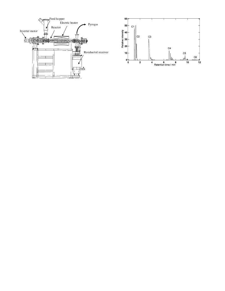
3.1. Moving-Bed Reactor. The bench-scale plant of the moving-
bed reactor is shown in Figure 1. This plant consists of a feed
hopper, tubular reactor equipped with a screw conveyor, electric
heater, and residue/oil receiver. The rotation rate of the screw
conveyor was controlled by an inverter motor. The tubular reactor
is made of stainless steel. The internal diameter and length of the
tubular reactor are 70 and 1200 mm, respectively. An electric heater
surrounds the reactor over a length of 900 mm.
The reactor temperature in this study represents the surface
temperature of the reactor, which is measured by three thermo-
couples attached to the outer surface of the reactor. Further, a 500-
mm section of the reactor is maintained at a constant temperature.
The reaction time is defined as the mean residence time of sand in
this section.
3.2. Samples and Analysis. Pellets (ca. 3 mm in diameter) of
polypropylene (MA3, Japan Polychem) were used as the sample
for gasification. A silica-alumina catalyst (Catalyst & Chemicals
Ind. Co., Ltd.) of a high alumina grade (Al
2
O
3
27.6%) was used.
The catalyst specifications are surface area 499 m
2
/g, pore volume
0.87 mL/g, and average particle size 63
µm. The average particle
size of sand was 0.3 mm. Gas evolution was monitored using a
gas meter connected to the gas outlet of the moving-bed reactor.
Chemical analyses of the gaseous and liquid products were
performed by gas chromatography equipped with a flame ionization
detector. Quantitative analyses of gaseous hydrocarbons were
calibrated by using methane, ethylene, ethane, n-propane for C3
isomers, n-butane for C4 isomers, n-pentane for C5 isomers, and
n-hexane for C6 isomers. The average molecular weights of gaseous
products were calculated on the basis of the gas analysis. Gas yields
were obtained from the calculated weights of gaseous products and
the weight of the plastic sample used as the feed.
3.3. Plant Operation. Polypropylene pellets (0.8 kg) were mixed
with sand (7.2 kg) and stored in the feed hopper. In the catalytic
reaction, polypropylene pellets (0.8 kg) were mixed with the silica-
alumina catalyst (0.4 kg) and sand (6.8 kg). The mixture was
supplied into the tubular reactor at a constant rate under a nitrogen
atmosphere. The internal pressure was maintained at atmospheric
pressure, and the reactor was maintained at a fixed temperature.
Analytical samples were collected from the gas outlet, and the
volume of gas evolution was monitored using a gas meter. After
feeding the sample mixture, the reactor was cooled overnight at
room temperature. The liquid product with sand goes into the
residue/oil receiver.
The receiver has a metal plate filter. Sand is stored on it, and oil
goes through the filter and is stored in the lower section of the
receiver.
4. Results and Discussion
A mixture of polypropylene pellets (0.8 kg) and sand (7.2
kg) was fed into the moving-bed reactor. Because polypropylene
pellets were mixed with sand, plugging of the feed sample did
not occur. Without the use of sand, sufficient heating to prepare
the polymer melt and a feeding device with a high-torque motor
are required. The moving-bed reactor using sand was applied
to solid plastics without pretreatment of melting a polymer.
Typically, polypropylene was converted into a mixture of
gaseous hydrocarbons at 82 wt % at a reactor temperature of
700
°
C and a reaction time of 10 min. In the reactor, solid
plastics were converted into a polymer melt, which is well
dispersed in sand. Although detailed data on the flow and
dispersion of the polypropylene melt in sand and the efficiency
of heat transfer of the heated sand were not obtained, we con-
firmed that gaseous hydrocarbons were the major products, and
this result can be explained by the repeated contact of the heavy
fractions of decomposed polypropylene with the heated sand.
Figure 2 shows the gas chromatogram of the resulting gaseous
products. The peak area is proportional to the weight of each
component. The gas composition was as follows: methane, 18.7
wt %; ethylene, 19.5 wt %, ethane, 9.7 wt %; propylene, 24.2
wt %; propane, 3.4 wt %; C4 isomers, 16.1 wt %; C5 isomers,
6.8 wt %; and C6 isomers, 1.3 wt %. Hydrogen generally
comprises less than 0.1 wt % in a reactor temperature range of
500-700
°
C and a reaction time range of 5-24 min. At the
reactor exit, the temperature of a vapor of the reaction mixture
exceeds 250
°
C. The vapor was cooled to a room temperature
in a vertical tube at a gas outlet, and a condensed fraction went
down to a residue receiver.
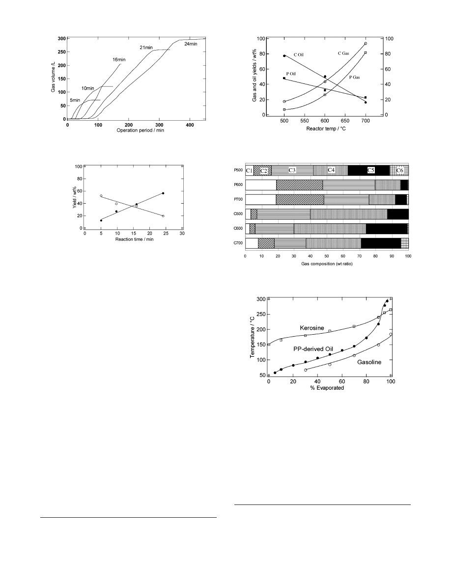
During the operation period, polypropylene was gradually fed
into the reactor and the gas evolution increased as shown in
Figure 3. The period prior to the gas evolution corresponds to
the time required by the plastic sample to reach the heated
section. The gas evolution stopped at the time when gasification
of polypropylene pellets from a feed hopper was completed.
At a reactor temperature of 600
°
C, the yields of gaseous
and liquid products were controlled by varying the reaction time,
as shown in Figure 4. The reaction environments were different
Figure 1. Bench-scale plant of the moving-bed reactor.
Figure 2. Typical chromatogram of the gaseous products at 700
°
C
for a reaction time of 10 min.
156 Energy & Fuels, Vol. 20, No. 1, 2006
Kodera et al.
from those in other reactors such as a tank reactor. For example,
the gas/liquid ratio is hardly controlled by using a tank reactor
because of the difficulties of changing the reaction time as well
as the reaction temperature of each portion of a feed and the
decomposed polymer. The results of the controllable ratio of
gaseous and liquid products using the moving-bed reactor
indicate that the rotation rate of the screw conveyor effectively
controlled the residence time of the polymer melt and liquid
products, which are precursors of gaseous products in the
presence of sand. In this research, the reaction time is defined
as the residence time of sand in the heated section at a constant
reactor temperature. The linear relationship observed in Figure
4 reveals that by varying the rotation rate of the screw conveyor,
the heating period of the heavy fractions from decomposed
plastics was readily controlled. We believe that during the
volatilization and condensation of the fractions, the gas yields
depend on the period of the repeated contact of the heavy
fractions of the decomposed polymer with the heated sand. The
total yield of gaseous and liquid products at 600
°
C was about
80 wt %. Because the formation of carbonaceous deposits was
within a few percent of the weight of a feed, the rest of the
products were considered as liquid products that remained in
the reactor.
It is noteworthy that the gas composition was almost constant
at various reaction times. The composition does not depend on
the reaction time, which is a variable parameter of the reactor,
because the screw conveyor cannot control the residence time
of gaseous products.
The effectiveness of the acid catalyst for the decomposition
of polyolefins was reported by some researchers.
6-13
With regard
to the functions of the silica-alumina catalyst, it is well-known
that it promotes cracking and isomerization of hydrocarbons.
However, it has been difficult to perform catalytic gas produc-
tion from a polymer in a bench scale because a suitable type of
reactor was not designed. To increase the gas yields and control
the gas composition, the moving-bed reactor was used for the
catalytic decomposition in the presence of the catalyst mixed
with sand (Figure 5). Increased yields of the gaseous products
were confirmed under catalytic conditions. Experimental errors
occur in the measurement of the oil yield because the yield
(6) Yamamoto, M. Nippon Kagaku Kaishi 1978, 1547.
(7) Uemichi, Y.; Ayame, A. Nippon Kagaku Kaishi 1980, 1741.
(8) Uemichi, Y.; Kashiwaya, M.; Tsudate, M.; Ayame, A. Bull. Chem.
Soc. Jpn. 1983, 55, 2767.
(9) Nanbu, H.; Sakuma, Y.; Ishihara, Y.; Takesue, T.; Ikemura, T. Polym.
Degrad. Stab. 1987, 19, 61.
(10) Ishihara, Y.; Nanbu, H.; Iwata, C.; Ikemura, T.; Takesue, T. Bull.
Chem. Soc. Jpn. 1989, 62, 2981.
(11) Ishihara, Y.; Nanbu, H.; Saido, K.; Ikemura, T.; Takesue, T. Polymer
1992, 33, 3482.
(12) Ishihara, Y.; Nanbu, H.; Saido, K.; Ikemura, T.; Takesue, T.; Kuroki,
T. Fuel 1993, 72, 1115.
(13) Sakata, Y.; Uddin, M. A.; Muto, A. J. Anal. Appl. Pyrolysis 1999,
51, 135.
Figure 3. Cumulative volume of gas evolution by pyrolysis. Reactor
temperature: 600
°
C, reaction time: 5-24 min, and gas temperature:
21-25
°
C.
Figure 4. Yields of gas (dots) and oil (circles) by pyrolysis at 600
°
C
for various reaction times.
Figure 5. Yields of gaseous hydrocarbons and oil under catalytic (C)
and noncatalytic (P) conditions at various reactor temperatures for a
reaction time of 10 min.
Figure 6. Gas compositions under catalytic (C) and noncatalytic
conditions (P). Reactor temperatures are 500, 600, and 700
°
C. Reaction
time for all runs is 10 min.
Figure 7. Distillation curves of a typical sample of polypropylene-
derived oil (catalytic decomposition at 600
°
C) and commercial
petroleum products.
Recycling Waste Plastics To Fuel Gas
Energy & Fuels, Vol. 20, No. 1, 2006 157
includes the total amount of oil in the oil tank of the residue/
oil receiver and the oil mixed with sand. The process of
weighing the sand and washing a part of it might lead to some
errors. Some portions of the oil product would remain in the
reactor and piping with it. Coke was obtained at 1-3 wt % of
the weight of the feed, and the coke was mainly deposited on
sand, which went out to a residue/oil receiver.
Figure 6 shows the gas composition under catalytic and
noncatalytic conditions. Heavier components such as C4 and
C5 were formed under catalytic conditions. Catalytic and
noncatalytic pathways are involved in the decomposition of the
polymer melt and liquid phase of the decomposition intermedi-
ates. Catalytic effects on the acceleration of macromolecular
transformation were observed in the degradation of polypro-
pylene at 180
°
C, at which temperature pyrolysis cannot be
expected.
12
A higher oil yield can be expected under catalytic
conditions. The C9 and C10 components were observed to be
important as the precursors of gaseous hydrocarbons.
12
Under
catalytic conditions, these components were rapidly converted
into the C4 and C5 components, respectively. Under noncatalytic
conditions, the C9 and C10 components were decomposed via
a radical mechanism, resulting in complex reactions that led to
an increase in the C1 and C2 components.
From the practical viewpoint of commercial operation, the
formation of a heavy gas such as C4 is desirable because it can
be easily liquefied and stored in a lightweight cylinder, which
is suitable for transportation. In Japan, liquefied petroleum (LP)
gas containing propane is used for domestic purposes such as
cooking and home heating in nearly half of the households. All
taxis in Japan also utilize LP gas containing butane. The moving-
bed reactor provides a simple small-scale recycling process for
waste plastics in order to produce fuel gas as an alternative to
LP gas. This process promises an economic recycling business.
Figure 7 shows the distillation curves of a typical oil sample
of the gasification byproduct and commercial petroleum prod-
ucts. As far as the boiling range is concerned, about 90 wt %
of polypropylene-derived oil can be used as a substitute for
commercial gasoline and kerosene. It can be used as fuel oil
for heating the reactor of a commercial plant. Upon pyrolysis
using the moving-bed reactor, polyethylene was also converted
into fuel gas containing a mixture of gaseous hydrocarbons,
whereas polystyrene decomposed to an oil product with styrene
as the major component. The oil product can be used as a fuel
oil for the gasification plant.
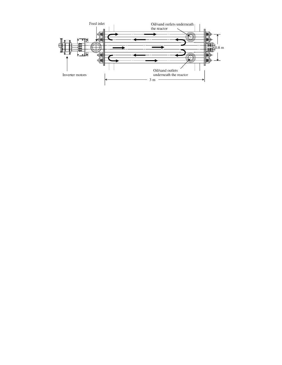
On the basis of the experimental results obtained using the
bench-scale moving-bed reactor, a demonstration plant was
designed. Figure 8 depicts the moving-bed reactor in the plant.
Waste plastics are continuously supplied to the feed inlet and
gaseous products evolve from gaseous product outlets. Similarly,
sand and decomposition residues are continuously removed from
the reactor by means of screw conveyors in the reactor. The
treatment capacity is 100 kg/h. Heating burners are attached to
the bottom of the reactor. Fuel oil for the burners is obtained
as a byproduct of plastic gasification. This demonstration plant
consists of two sections of multiple tubular reactors. The twin-
screw conveyor in the first section is connected to two single-
screw conveyors in the second section. The rotation of all
conveyors is synchronized, and inverter motors can vary the
rotation rate. These reactors are heated by burners. Shredded
waste plastics are continuously supplied to the reactor by means
of a feed hopper. The feed is heated and melted in the first
tubular, in which a screw conveyor is installed. The resulting
polymer melt is then decomposed in the following reactors
equipped with other screw conveys; these reactors are located
on either side of the first tubular reactor. The operations research
of the demonstration plant will be reported in the future.
Considering the results mentioned in this paper, it would not
be difficult to optimize the reaction conditions, especially
reaction time, for gas production in a demonstration plant
because of the effectiveness of a screw conveyor in the presence
of sand.
5. Conclusion
A novel process for recycling waste plastics to fuel gas has
been proposed. Considering the role of sand as an effective
heating medium and by using a reactor structure for suitably
controlling the reaction temperature and reaction time, a new
type of reactor has been developed; this reactor is termed the
moving-bed reactor and is equipped with a screw conveyor. In
the operations research of the new process using the moving-
bed reactor, the formation of gaseous hydrocarbons from
polypropylene was achieved at 82 wt % (pyrolysis) and 94 wt
% (catalysis). The configuration of a 100-kg/h demonstration
plant was also described.
Acknowledgment. We thank Mr. Noriyuki Fujimura (Nihon
Axis Co., Ltd.), Ryohei Sato, Manabu Miyamoto (Nagaoka
University of Technology), and Mrs. Chikako Matsushita (AIST)
for technical assistance. We are also grateful to Prof. Ryohei
Yamada (Nagaoka University of Technology) for his support.
EF0502655
Figure 8. Structure of a demonstration plant of the moving-bed reactor with a treatment capacity of 100 kg/h. The arrows indicate the flow of the
mixture of plastic sample and sand. Oil products and sand are discharged from the outlets underneath the end of the reactor. Gaseous products
escape through the gaseous product outlet on the reactor.
158 Energy & Fuels, Vol. 20, No. 1, 2006
Kodera et al.
Wyszukiwarka
Podobne podstrony:
Herbs for Sports Performance, Energy and Recovery Guide to Optimal Sports Nutrition
04a Energy Efficiency Mevenkamp 2006
brzuch i miednica 2005 2006 20 01
Energy and security
Psychologia rozwoju człowieka, TEMAT 8 - 20.III.2006, 20
Herbs for Sports Performance, Energy and Recovery Guide to Optimal Sports Nutrition
James E Perone The Sound of Stevie Wonder, His Words and Music (2006)
SMeyer WO8901464A3 Controlled Process for the Production of Thermal Energy from Gases and Apparatus
Energy and Nutritional Properties of the White Mulberry
Energy and CO2 analysis of poplar and maize crops for biomass production in Italy Włochy 2016
155 158 407c pol ed01 2008
Energy and greenhouse balance Ouafik
04 Wind Turbine Power, Energy And Torque
20 20 Cookbooks Presents 85 Fat Burning Diet Meal Recipes to Help You Lose Weight Faster and Stay Fu
Energy Savers Tips on Saving Energy and Money at Home
The Energy Bus 10 Rules to Fuel Your Life, Work, and Team with Positive Energy ( PDFDrive )
więcej podobnych podstron