
An IGBT Inverter for Interfacing Small Scale Wind Generators to
Single Phase Distributed Power Generation System
* Chem Nayar, Hooman Dehbonei and **Liuchen Chang
*Department of Electrical and Computer Engineering
Curtin University of Technology
GPO Box U 1987 Perth 6854
AUSTRALIA
E-mail: c.v.nayar@curtin.edu.au
** Department of Electrical and Computer Engineering
University of New Brunswick
Fredericton NB E3B 6Y1
CANADA
Abstract
This paper presents a low cost power electronic interface for interfacing variable speed small scale
wind turbine generators to a single phase distributed generation system. The power electronics
architecture employs an AC/DC/AC topology for converting the variable power input from a permanent
magnet wind generator to a constant voltage, constant frequency grid. The IGBT inverter is
unidirectional transformer less and is able to extract power even at very low wind speeds. Preliminary
experimental and simulation results are included.
1. INTRODUCTION
A distributed power generation system contains combination of small wind turbines, small hydro
turbines, photovoltaic generators, micro turbines and fuel cells that are connected to a power system
grid which is located in close proximity to electricity consumers. Distributed power generation systems
offer secure and diversified fuel options with low or zero greenhouse gas emissions. As an emerging
technology, distributed power generation is at an early stage of development. There are technical
issues associated with the integration of new and renewable energy sources with an existing power
grid.
Electricity generation using wind energy has been regarded as environmentally friendly and
economically competitive renewable energy technology. While most large companies are focusing on
large wind turbines of the utility scale, small wind turbines as distributed power generators have
attracted a growing interest from the general public, small farms and remote communities. According
to the American Wind Energy Association, the market for small scale wind generators is growing at
around 35% per annum. UK based consultants Gerrad Hassan also predicts that small wind turbine
sales have the potential to increase to well over US$750 million by 2005.
Most of the manufacturers of small-scale wind turbines currently sell their products for battery charging
applications only. Because of the lack of a single phase generating system, they are unable to exploit
the emerging distributed generation area market, which consists almost exclusively of single-phase
applications.
The type of generator for small scale wind generation is required to be compact and light so that the
generators can be conveniently installed at the top of the towers and directly coupled to the wind
turbines. Compared with a conventional, gearbox-coupled wind turbine generator, directly coupled
generators have a series of advantages, such as a much reduced size of the overall system, a rather
low installation and maintenance cost, a flexible control method, a quick response to the wind
Low Cost Inverter for Small Scale Wind Generators
Nayar
Solar 2004: Life, the Universe and Renewables
2 of 12
fluctuation and load variations, etc. Many small wind turbine generators consist of a variable speed
rotor driving a permanent magnet synchronous generator. Potentially, permanent magnet (PM)
generators offer a high efficiency in operation and a simple and robust structure in construction
because no field current and winding is used(J. Chen, 2000). The attractiveness of PM generators is
further enhanced by the availability of high-energy PM materials such as neodymium-iron-boron.
The principal application of small wind generators are for battery charging in which the generator
connected through a rectifier to a battery bank (Muljadi et al., 1996). There is growing market for a grid
interactive small wind generating system (without battery storage) for home owners and small
businesses in rural areas. In this case the excess energy form the wind generator is fed to the utility
grid. The AC grid can also be a diesel grid or a battery / diesel mini hybrid grid. A low cost grid
interactive inverter structure which extracts energy even at low wind speeds will assist in reducing
capital cost and offer opportunities for interfacing small-scale wind generators with the AC grid. The
authors are involved in investigating various grid interface options for small scale variable speed
permanent magnet generators, examine their potential to meet the waveform, power factor, cost and
efficiency requirements, as well as application of this technology for strong grid, weak grid and stand-
alone battery/diesel hybrid systems.
2. AN IMPROVED POWER ELECTRONIC INTERFACE
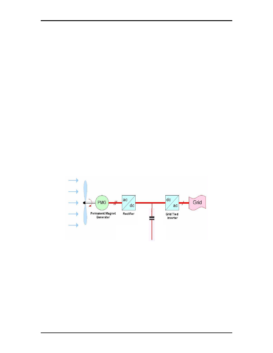
Random output variation is one of the significant characteristics of wind power. With a PM generator
coupled to a wind turbine, the voltage output will be varying with its rotor speed because of the wind
speed variation. A typical wind generator may have a voltage variation of 1 to 5. The earliest and still
most widely used power electronic circuit uses the AC/DC/AC topology, in which the variable
frequency, variable voltage from a variable source is first rectified to DC and fed to DC link capacitor
with or without a DC-DC converter/chopper (Figure 1). The continuous variation of wind speed will
result in a DC link voltage varying in an uncontrolled manner with a more demanding role and
specification for the DC-AC inverter.
Link
DC
Figure 1. A typical AC/DC/ LINK a wind generator
Several types of inverters have been proposed for variable speed wind energy conversion. The line-
commutated inverter (LCI) is commonly used to transfer power from a dc bus to the three-phase ac
grid because of low cost, simplicity, reliability and availability in high power levels (N. Mohan, 1995).
However, it produces reactive and harmonic currents that would lead to problems for the power
system operation. Combination of a line-commutated inverter and active power filters has some
benefits –but only for large power installations (R. Naik, 1995, H. H. Tumbelaka, 2003). Inverters using
high switching frequency (forced commutated) insulated-gate bipolar transistors (IGBTs) have
replaced traditional (line commutated) thyristor inverters because of their superior performance in
terms of reactive and improvement in total harmonic distortion (THD).
The force commutated Voltage Source Inverters (VSI) can be classified as ‘voltage controlled voltage
source inverter’ (VCVS) and ‘current controlled voltage source inverter’ (CCVSI), depending upon the
control of the power stage. CCVSIs can offer better dynamic performance due to closed loop control
than VCVSIs. There are different methods of current control in CCVSIs such as hysteresis, ramp
Low Cost Inverter for Small Scale Wind Generators
Nayar
Solar 2004: Life, the Universe and Renewables
3 of 12
comparison or predictive controllers. Hysteresis current controllers, presented in [5], utilize hysteresis
in comparing load currents to current references. Hysteresis current controllers have the advantage of
simplicity and robustness, but converters' switching frequency largely depends on the load parameters
and consequently the load current harmonics ripple is not optimal. Ramp comparator controllers
compare the error current signal to a triangular carrier waveform to generate the inverter firing pulses
[9]. The main advantage of the ramp comparison technique is that the inverter switching frequencies
are usually limited to the frequency of the triangular waveform, and the produced harmonics are
distributed at fixed frequencies. Predictive controllers calculate the inverter voltages required to force
the current to follow the current reference [11] [12]. This method offers the potential for achieving more
precise current control with minimum distortion, but needs more calculations and requires a good
knowledge of system parameters.
2.1.
Prototype Implementation
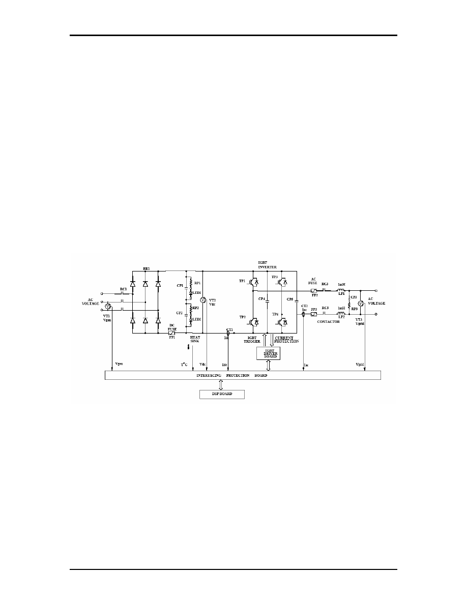
Figure 2 illustrates the basic power stage of the single phase prototype inverter developed by the
authors. It consists of a power circuit module, an interfacing and sensing module, a DSP-based control
module, and an IGBT driver module. The input of the inverter is connected to a three-phase generator
driven by a wind turbine. The dc link voltage varies in response to the generator terminal voltage
which depends on the wind conditions. The rated input line-line voltage from the generator is 280V
rms, corresponding to a dc link voltage of 378V. The output of the inverter is connected to a single-
phase grid. The power circuit module includes a three-phase rectifier, dc filter capacitors, a full bridge
single-phase inverter, a filter inductor and a low pass RC filter.
Figure 2. Prototype power electronics interface
Computer simulation and experimental verification were carried out using prototyped 5 kW and 10 kW
inverters.
2.1.1. Computer
Simulation
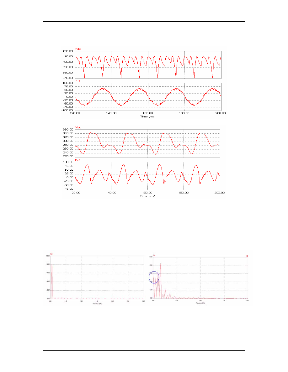
The power electronics simulation software, PSIM, was used in the simulation of the inverter. Figure 3
shows how the DC link voltage affects the output current of a normal IGBT inverter. If the DC link
voltage is high enough, the output current can be controlled to be a sinusoidal waveform complying
with typical utility power quality requirements (such as total harmonic distortion <5%) (Figure 3(a)).
When the DC link voltage reaches a low value (at a low wind speed), the energy flow will be from the
grid to the DC link. This results in excessive reactive power flow and harmonic distortion (Figure 3(b)).
At low wind speeds, the DC bus might not meet the minimum requirements for the inverter and its
controller. Hence, the control system loses its ability to control the output current. In such a case, the
Low Cost Inverter for Small Scale Wind Generators
Nayar
Solar 2004: Life, the Universe and Renewables
4 of 12
inverter will inject a highly distorted current to the grid including a DC component which is highly
undesirable.
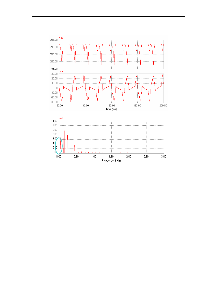
A normal IGBT full bridge (H-Bridge) inverter will have to be disconnected in low DC link voltages
because of possibility of DC current injection as can be seen from the simulation results of Figure 4.
This means that the wind energy conversion system will fail to extract energy available at low wind
speeds such as 3-5 m/s. In many locations this energy could be as high as 20% yield from the wind
generator on a yearly basis.
(a) (b)
Figure 4. Fast Fourier Transform (FFT) at input line-line voltage a) = 290V, b)= 150V. The DC injection is
shown in circle
Our modified inverter has a better current waveform at the same input AC voltage (150V), with
significant improvement in reactive and harmonic performance at low wind speeds (Figure 5(a)). In
(a)
(b)
Figure 3. Simulation results DC link voltage and line current at, a) line to line voltage
=290 V, and b) line to line voltage =150 V
Low Cost Inverter for Small Scale Wind Generators
Nayar
Solar 2004: Life, the Universe and Renewables
5 of 12
addition to improving the THD, our modified inverter scheme can prevent DC injection to the AC grid
(Figure 5(b)). Hence it is possible to use this scheme without a low frequency (50Hz) transformer,
which reduces the overall cost, weight and size of the power electronic interface.
2.1.2. Laboratory
Experimental
Results
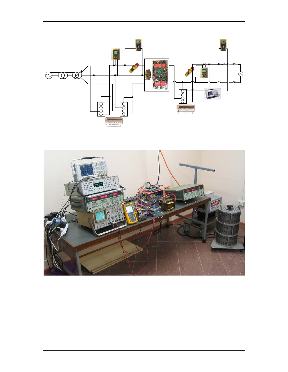
Two prototype inverters, one rated at 5kW and the other rated at 10kW were built. Figure 6 shows a schematic
diagram of the experimental set up used to test the performance of the power electronic interface. The variable ac
voltage input was obtained through the combination of a three phase isolation transformer and a variac. The
output from the inverter was then connected to the 240V, 50 Hz single phase supply. Figure 7 shows a
photograph of the experimental setup.
(a)
(b)
Figure 5. a) Current waveform for the proposed unidirectional inverter at input
line voltage = 150V, b) FFT result
Low Cost Inverter for Small Scale Wind Generators
Nayar
Solar 2004: Life, the Universe and Renewables
6 of 12
A
±
±
V
A
±
±
V
3Ø 3W Connection
FLUKE 43
Power Quality Analyzer
a
b
c
INPUT
3
YOKOGAWA 2533
Digital Power Meter
3Ø 415V Supply
440V Isolation
transformer
0-440V VARIAC
+
-
-
A
±
±
V
240 V
Single Phase
1Ø 2W Connection
FLUKE 43
Power Quality Analyzer
OUTPUT
1
CH 2
CH 1
Circuit Breaker
YOKOGAWA 2533
Digital Power Meter
-
+
+
-
Vg
CH3
0.1
Ω
FLUKE 179
FLUKE 179
DIGITAL MULTI METER
DIGITAL MULTI METER
1400V 70A
1400V 70A
5KW INVERTER
FLUKE 330
CLAMP METERS
FLUKE 330
CLAMP METERS
Figure 6. Schematic diagram of the experimental setup
Figure 7. The experimental setup
Low Cost Inverter for Small Scale Wind Generators
Nayar
Solar 2004: Life, the Universe and Renewables
7 of 12
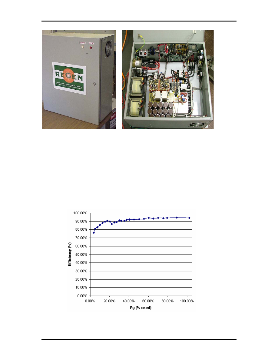
Figure 8. The prototype inverter
From the recommended testing procedures as set out in Standard 4777.2, the experiments were
conducted to estimate the following:
• Efficiency
• Displacement Power Factor (DPF) and Power Factor (PF)
• Current
harmonics
• Performance Analysis of the gird as a Wind Generator simulator
• Verification of the measurements
• DC injection to the Grid
The efficiency curve with respect to the injected power to the grid is given in Figure 9. The inverter
offers very high efficiency for more than 5% of the rated power output.
Figure 9 Efficiency vs.10kW Inverter Output Power (%)
Low Cost Inverter for Small Scale Wind Generators
Nayar
Solar 2004: Life, the Universe and Renewables
8 of 12
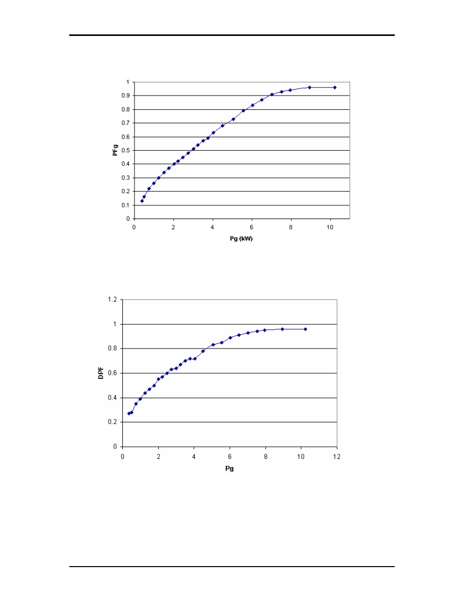
The grid power factor varies with respect to the injected power to the grid which is given in Figure 10. it
may be noted that the inverter can offer higher power factor for outputs greater than 7kW (70% of the
rated power).
Figure 10 Output Power Factor vs. Output Power of 10kW Inverter
The grid displacement power factor (DPF) variation is shown in Figure 11. At full power the DPF
becomes near to the unity which explains possibility of some phase shift and/or lower order at around
nominal power rating and more at low power operating conditions.
Figure 11 Grid Displacement Power Factor vs. 10kW Inverter Output Power Output
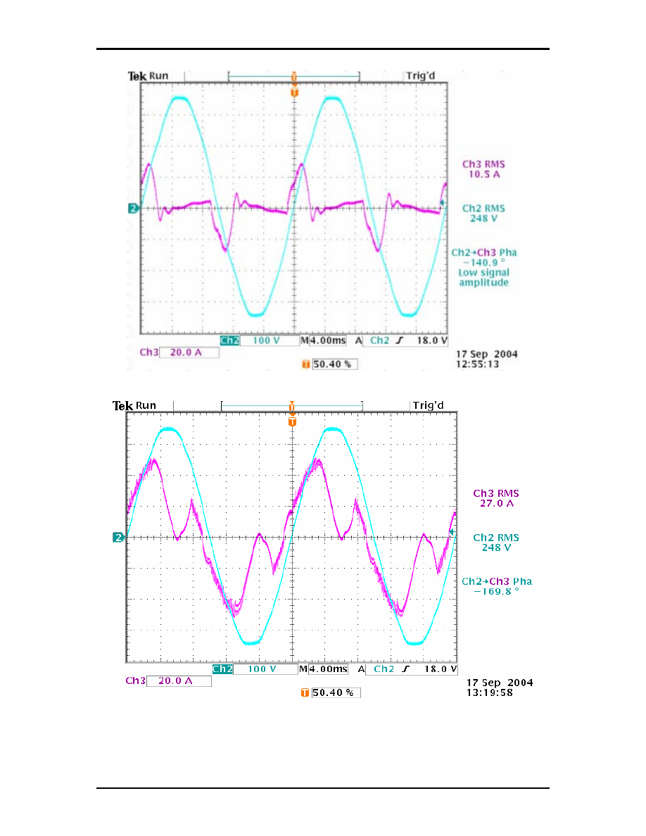
Figure 12 - Figure 14 show the grid voltage and the current waveforms at different power output
conditions. The distortion of the current waveforms at low output power levels are expected as the DC
link voltage is less than the instantaneous grid voltage at part of the cycle. This can be solved by
methods such as boosting the DC link voltage , tap changing of the AC voltage, having two winding in
the alternator and switching in external excitation capacitors at the machine terminals.
Low Cost Inverter for Small Scale Wind Generators
Nayar
Solar 2004: Life, the Universe and Renewables
9 of 12
Figure 12 Grid voltage and current at 0.373kW
Figure 13 Grid voltage and current at 5.061kW
Low Cost Inverter for Small Scale Wind Generators
Nayar
Solar 2004: Life, the Universe and Renewables
10 of 12
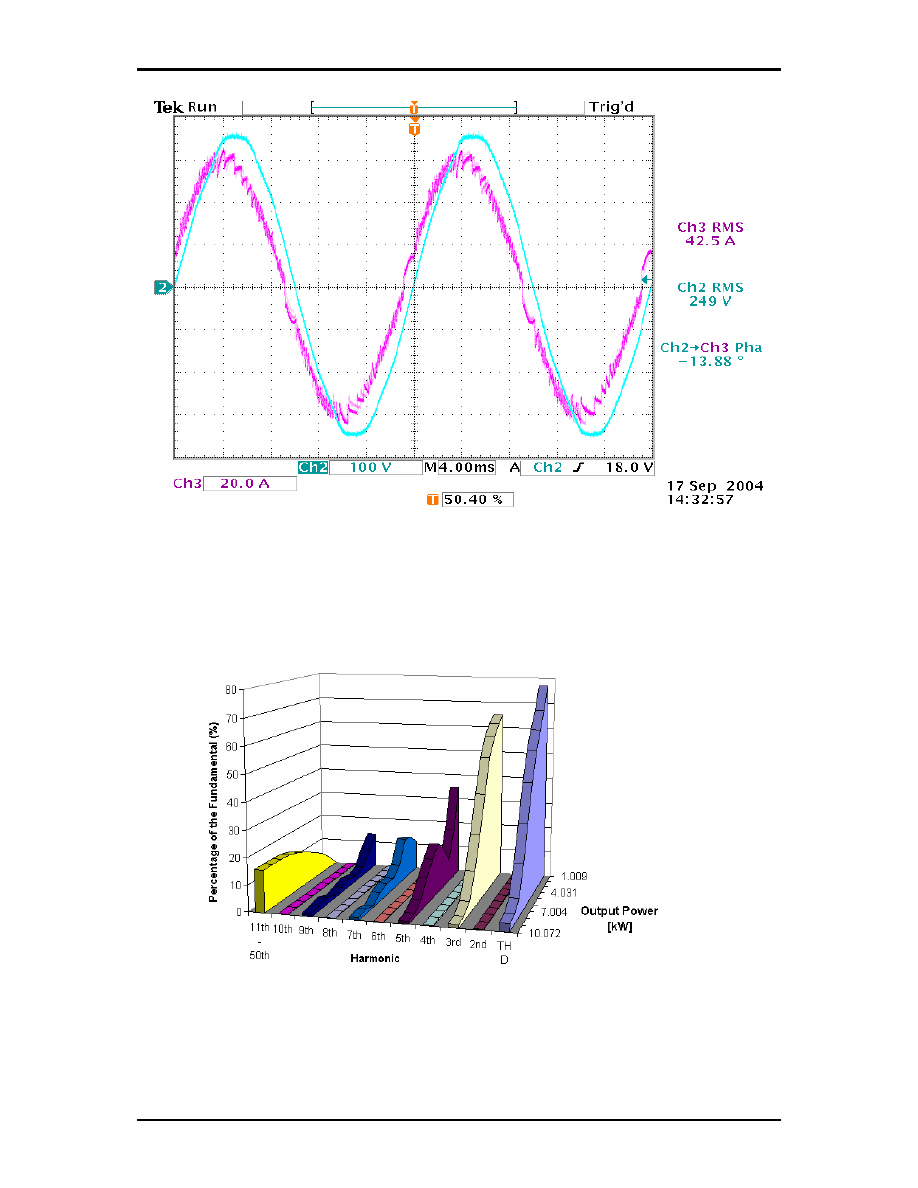
Figure 14 Grid voltage and current at 10.22kW
Figure 15 shows the variation of the total harmonic distortion (THD) at different power output levels. As shown
the inverter generates only odd harmonics - even harmonics are negligible (as the current waveform is
symmetrical to the time axis). AS explained earlier the inverter generates low order harmonics at low power
levels which will be gradually improved as the DC voltage increases at higher power levels. The inverter can
satisfy the standard THD (less that 4%) only for operating power more 90% of rated power.
Figure 15. 2nd-50th Output Harmonics vs. Output Power of 10kW Inverter
2.2. Field
Test
Results
The prototype inverter was also tested at the CRESTA field site at Curtin University of Technology.
Low Cost Inverter for Small Scale Wind Generators
Nayar
Solar 2004: Life, the Universe and Renewables
11 of 12
The CRESTA wind turbine was originally connected to a battery bank through a charge controller. In
order to connect the wind turbine to the 240V grid, the inverter available to us at CRESTA was
modified. A step-up transformer was connected between the generator and the inverter. A Labview
based monitoring system was developed to record the performance of the wind generator. The wind
speed, the shaft speed (using the AC voltage), the active power and the reactive power were
recorded.
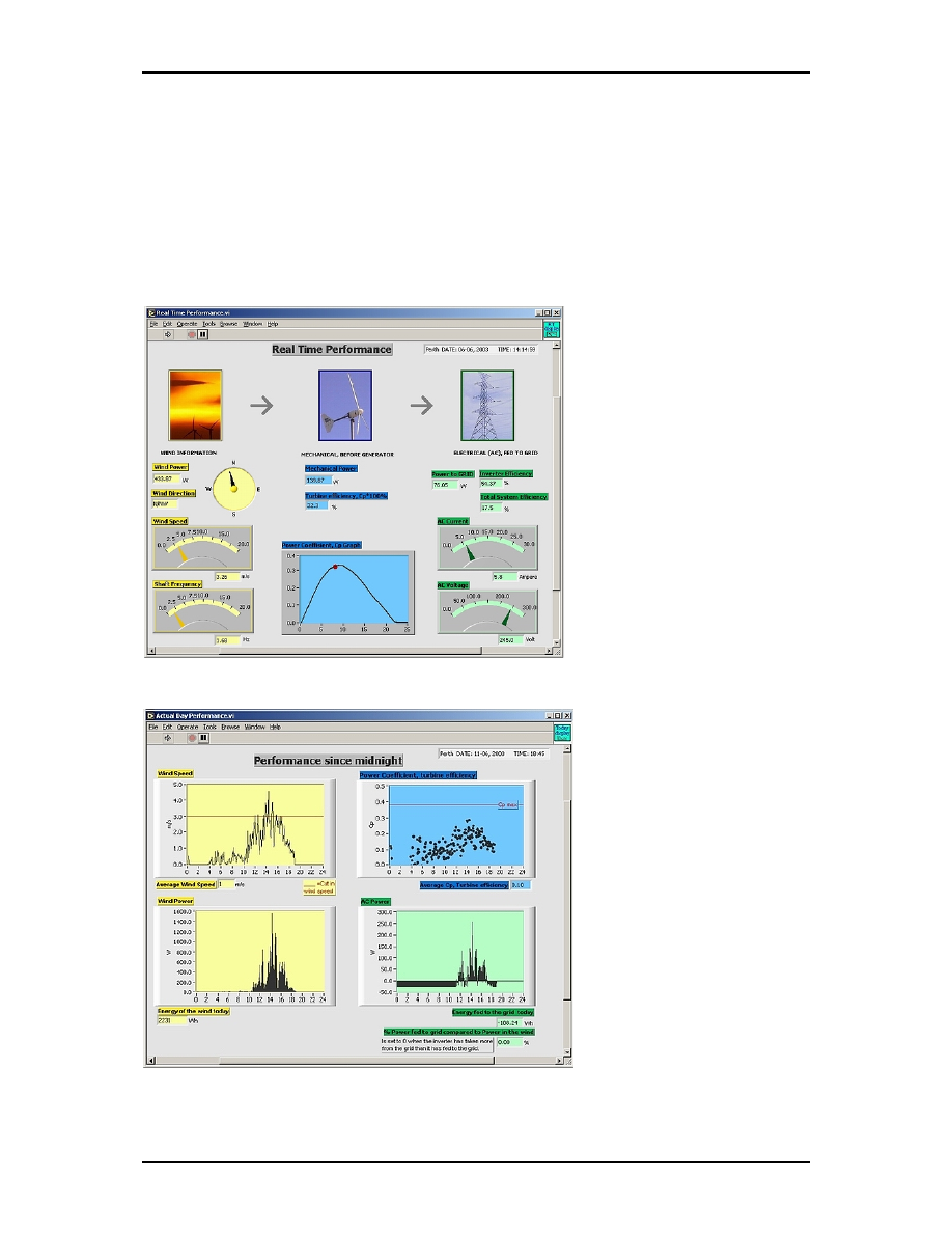
Figure 16 shows a display of the Labview based measurement system. The performance coefficient of
the turbine (Cp) at various tip speed ratios, wind speed, and power fed to the grid are displayed. Figure
17 shows display of the instantaneous wind speed, computed power output from the 5kW wind
generator computed power coefficient and the AC power fed to the grid.
Figure 16. LabView based real-time performance of a small wind energy conversion system
Figure 17. LabView based daily performance of a small wind energy conversion system

Low Cost Inverter for Small Scale Wind Generators
Nayar
Solar 2004: Life, the Universe and Renewables
12 of 12
3. CONCLUSION
An improved power electronic interface for connecting small scale wind turbines with utility grid or mini
diesel grid is proposed. Computer simulation, laboratory tests and field tests have demonstrated the
commercial viability of this equipment. However, further work is required to improve the power quality
at low wind speeds. In addition, it is suggested that test such as EMC/EMI, protection (eg., islanding,
impulse) and voltage fluctuation and flicker in the power system are carried out. Further field test is
required to establish the energy recovery at low wind speeds.
4. ACKNOWLEDGEMENT
The authors are grateful to Curtin University of Technology for providing equipment and other test
facilities to carry out this research. The Australian Research Council Linkage Project Grant LP
0348994 funded the salary of Dr Dehbonei (Post Doctoral Research Fellow) to work on this project.
The equipment and consumables component of this project has been funded by a SEDO grant
(C329). The authors are grateful to the funding agencies and the industry partners associated with
this project.
5. REFERENCES
H. H. Tumbelaka, C.V. Nayar, L.J. Borle, K. Tan (2003) Active Filtering applied to a Line-Commutated
Inverter Fed Permanent Magnet Wind Generator, In 6th IPEC Singapore.
J. Chen, C.V. Nayar, L. Xu, (2000) Design and finite-element analysis of an outer-rotor permanent-
magnet generator for directly coupled wind turbines, In IEEE Transactions on Magnetics, Vol. 36, pp.
3802 -3809.
Muljadi, E., Drouilhet, S., Holz, R. and Gevorgian, V. (1996) Analysis of permanent magnet generator for
wind power battery charging, In Industry Applications Conference, 1996. Thirty-First IAS Annual
Meeting, IAS '96., Conference Record of the 1996 IEEE, Vol. 1, pp. 541-548 vol.1.
N. Mohan, T.M. Undeland, W.P. Bobins (1995) Power Electronics- Converters, Applications and Design,
John Wiley & Sons.
R. Naik, N. Mohan, M. Rogers, A. Bulawka (1995) A novel grid interface, optimized for utility-scale
applications of photovoltaic, wind-electric, and fuel-cell systems, In IEEE Transactions on Power
Delivery, Vol. 10, pp. 1920 -1926.
Wyszukiwarka
Podobne podstrony:
Development Of A Single Phase Inverter For Small Wind Turbine
An 9021 A Novel Igbt Inverter Module For Low Power Drive Applications
Microprocessor Control System for PWM IGBT Inverter Feeding Three Phase Induction Motor
Microprocessor Control System for PWM IGBT Inverter Feeding Three Phase Induction Motor(1)
Operation of an IGBT in a self clamped inductive switching circuit (SCIS) for automotive ignition p
small scale water current turbines for river applications
0 Alternative Composite Materials for Megawatt Scale Wind Turbines Griffin Ashwill 2003
Single Phase Line Frequency Commutated Voltage Source Inverter Suitable for fuel cell interfacing
Microprocessor Control System for PWM IGBT Inverter Feeding Three Phase Induction Motor(1)
Operation of an IGBT in a self clamped inductive switching circuit (SCIS) for automotive ignition p
Microprocessor Control System for PWM IGBT Inverter Feeding Three Phase Induction Motor
A Digital Control Technique for a single phase PWM inverter
Conducted EMI in PWM Inverter for Household Electric Appliance
Inverter For Domestic Fuel Cell Applications
Plans For Wind Generator Pt250 Blade Plan10A
Battery Inverter For Modularly Structured Pv Power Supply Systems
Design of a 10 kW Inverter for a Fuel Cell
Control of a 4 leg Inverter for Standalone Photovoltaic Systems
więcej podobnych podstron