
BATTERY INVERTER FOR MODULARLY-STRUCTURED PV POWER SUPPLY SYSTEMS
B. Burger, P. Zacharias
Institut für Solare Energieversorgungstechnik (ISET) e.V.
Königstor 59, D-34119 Kassel, Germany, Tel. +49 561 7294-142, Fax: -100
G. Cramer
SMA Regelsysteme GmbH
Hannoversche Straße 1- 5, D-34266 Niestetal, Germany, Tel. +49 561 9522-0, Fax: -100
W. Kleinkauf
Universität Gh Kassel, Institut für Elektrische Energietechnik (IEE)
Wilhelmshöher Allee 71-73, D-34109 Kassel, Germany, Tel. +49 561 804-6344, Fax: -6512
ABSTRACT: The electricity supply in remote areas without public utility is very important worldwide, particularly in
developing and threshold countries. This is an ideal application for isolated or “off grid” hybrid power supply
systems. ISET developed a completely new bi-directional battery inverter with a rated power of 3.6 kW for such
systems in cooperation with SMA Regelsysteme GmbH. Power ranges from 3.6 kW to 33 kW can be established
with the parallel connection of inverters in single phase and three phase systems due to the modular design of
the battery inverter. All power producers and consumers are coupled at the AC line in these modular systems.
Keywords: Hybrid - 1: Stand-alone PV Systems - 2: Inverter - 3
1.
INTRODUCTION
The supply of small, peripheral consumers in the
power range from 2 to 30 kW, which cannot be
attached to a public grid, is worldwide, in particular in
the developing and threshold countries, from large
relevance. This is an almost ideal application for
isolated or “off grid” photovoltaic power supply
systems. The experiences with such systems have
shown that these systems should be not only very
reliably, economical and robust, but above all
modularly structured and therefore easily
subsequently expandable [1]. Also the connection of
diesel generator sets and small wind energy systems
should be possible in a simple manner. Only a simply
structured and flexible system design for these
photovoltaic power supply systems will enable a wide
spread application.
On the basis of these requirements, the ISET in
cooperation with SMA and with promotion of the
German Federal Ministry BMWi developed the
completely new battery inverter “Sunny Island” with a
nominal output power of 3.6 kW. The usage of
advanced microprocessor technology in combination
with new power electronic circuit concepts provides a
simply applicable and expandable system
engineering for the power supply of remote areas.
2. THE BATTERY INVERTER
The central component of such a modular supply
system is a battery inverter with the product name
Sunny Island [2],[3]. The AC output of the inverter
must provide constant voltage and frequency for the
consumers. A lead acid battery is used as energy
buffer. Intelligent management and control algorithms
integrated in the device enable it to supply not only
different consumers but also to connect different
generators, e.g. string inverters, small wind energy
converters or diesel generator sets. The battery
inverter must therefore be able to operate it in all four
quadrants.
This requires the control of voltage, frequency, active
power and reactive power of the AC voltage of the
battery inverter. With appropriate coupling of three
devices a three phase power supply is possible and
by the direct parallel connection of several inverters
at a phase an increased power will be achieved (in
development). For simple configurations the battery
inverter is able to take over the battery management
and load management.
The DC voltage is controlled to provide a best
possible battery handling, with respect to temperature
dependent and current dependent voltage limits, the
execution of regular total charge cycles and the
adaptation of the charging algorithms to the battery
type and the application conditions. Additionally the
state of charge of the batteries is calculated and
displayed.
The following requirements for battery inverters in
modular structured island systems can be fulfilled:
•
Operating modes: Voltage control - current control
- parallel operation,
•
Modular
expandability,
•
Extendibility for 1 and 3 phase island grids,
•
Intelligent battery management for longest battery
life: Charging and discharging control, regular full
charging
•
State of charge display
•
Load management for simple basic configurations
of small systems and
•
High efficiency, also in the partial load range with
low stand by losses.
To create a flexible applicable device, closed loop
control and local management system (operational
control) are taken over by its own processor. This
allows the integration of a fast closed loop control
and a complex management into the new battery
inverter. The fast control allows the required
operation modes and a parallel connection of
inverters. The management system takes over the
battery management, enables a limited load
management and makes communication interfaces
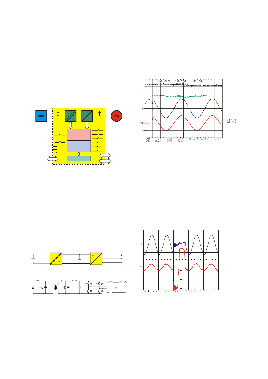
available for optional management devices. Figure 1
shows a block diagram of the battery inverter. The
battery and the AC output are connected via circuit
breakers. There are 8 relay contacts available for the
following tasks:
•
Starting a generator and connecting it to the
island grid
•
Switching of wind energy, consumers, utility and
dump load
•
Automatic control of the fan for the battery room
and an optional electrolyte circulation pump.
63 A DC
16 A AC
fan
circulation
battery temp.
generator voltage
battery
e.g. 60 V
island grid
230 V, 50/60 Hz
generator current
3-phase
synchroni-
zation
communi-
cation
generator start
generator connect
wind energy
consumers
utility
dump load
Powerline
RS485
RS485
closed loop
control
management
system
display
Figure 1: Block diagram of the battery inverter
2.1 Circuit of the static inverter
Figure 2 shows the power electronic circuit of the
battery inverter. A bi-directional Cuk converter
changes the battery voltage, which depending upon
number of cells and charge can be between 40 V and
80 V, into a regulated DC-link voltage of 380 V. The
HF transformer provides a electric separation
between battery and grid, so that the battery is
potential free. By the high frequency of 16.6 kHz the
transformer is substantially lighter and smaller than a
comparable transformer for 50 Hz. To the DC-link a
single phase inverter with L-C-L filter is connected,
which generates the sinusoidal voltage for the island
grid. Since both, the Cuk converter and the inverter
operate bi-directional, the static inverter can charge
and discharge the batteries.
L
N
PE
inverter
3.6 kW / 4 kVA
single phase
island grid
bidirectional
DC-DC converter
DC-link
380 V
battery
60 V
L1
S1
S2
S3
S4
S5
S6
C1
Tr
C2
L2
L3
L5
C4
C3
L4
=
~
Figure 2: Circuit of the static inverter
2.2 Closed loop control
For the control of the Cuk converter a state
control with overlaid closed loop PI control is used for
DC-link voltage control. The digital closed loop
control operates at the half clock frequency of the
hardware, i.e. with 8.3 kHz.
Figure 4 shows the behavior of the closed loop
control during a load branch with 2 kW. The voltage
V
grid
(channel 3) has only a short drop after switching
and reaches already after approximately 1 ms again
its desired value. A further improvement of the
dynamics would be possible only with a higher DC-
link voltage, since the inverter here already operates
as control in the delimitation. This would increase
however the losses of the power electronic
components, so that the efficiency would be reduced.
Ch1: V
bat
Ch2: V
link
Ch3: V
grid
Ch4: I
grid
Figure 4: Load branch with 2 kW
If the output of the inverter is short circuit, an
additional closed loop control for the choke current
limits the output current of the inverter to the
maximum current, which the power semiconductors
can process. This current is higher than 60
A
resulting in the fact that the inverter is able to trip
normal circuit breakers of Class A with a rated
current of 16 A. Figure 5 shows a measured short
circuit. During the short circuit the voltage V
grid
is
nearly zero and the current I
grid
rises to the current
limit. After approximately 15 ms the circuit breaker
trips and the voltage rises again on its desired
sinusoidal value. Thus a selective protection is
possible by circuit breakers in the island system just
as in the public grid.
Ch1: V
grid
Ch2: I
grid
Figure 5: Short circuit over a 16 A circuit breaker
2.3 Management system
The management system is responsible for all
functions, which do not have to be processed faster
than in one second. These are above all
communication over the serial interfaces and the user
interface via keyboard as well as the graphic display.
Additionally the management determines the
operating mode. The following operating modes are
implemented:
2.3.1 Voltage controlled operation
In the voltage controlled operation mode the
output voltage of the inverter is regulated to its RMS
value. The output frequency can be defined with a
resolution of 10 mHz, the RMS value of the voltage
with a resolution of 100 mV. A change from 50 Hz to
60 Hz can be made easily by software.
2.3.2 Current controlled operation
In the current controlled operation mode the
inverter synchronizes to an external voltage supply.
This can be a public grid or a generator. Depending
on the given direction of current, the battery can be
charged in this operating mode or the grid can be
supported.
2.3.3 Three phase operation
In the three phase operation mode three inverters
operate with 120° offset, so that a three phase
current supply system is established. Synchronization
is done with a digital interface.
2.3.4 Parallel operation
In the parallel operation mode several inverters
operate synchronized on one phase, so that the
available output power is increased to a multiple of
3.6 kW.
2.4 Battery management
The battery management is responsible for the
charging and discharging control of the battery. It
calculates the desired value for the charging voltage
and is able to start an additional generator over relay
outputs, in order to charge the batteries additionally
to the PV power. When the battery has a low state of
charge, a low priority load can be disconnected from
the grid by another relay. In the case of a fully
charged battery, a dump load will be connected or
the PV power will be disconnected or short circuited.
Additional relays are available for controlling a fan for
the battery room and for the pump of an electrolyte
circulation system.
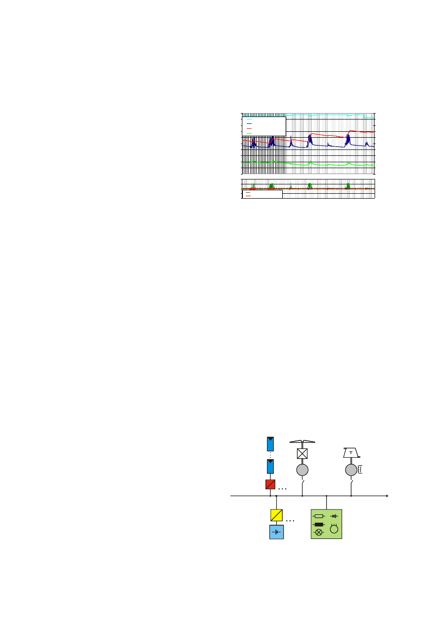
For the calculation of the state of charge of the
battery an algorithm is integrated, which uses a
balance of ampere-hours combined with a calculation
of losses and multilevel full charge recognition. Also
an adapting current-voltage model of the battery is
used to recalibrate the state of charge when the
battery is not fully charged [4]. For the current-voltage
model the linear correlation between the open-circuit
voltage and the state of charge is used. The
correlation is determined in phases after a full charge
by means of the then well known ampere-hours
balance. This is important, since the correlation
between open-circuit voltage and state of charge for
different battery types can be very different. Thus it
becomes possible in most PV systems, the ampere-
hour balance not only to recalibrate after full charges
but practically each night, when the battery is
discharged only with small currents. By the definition
of a lower open-circuit voltage for the end of
discharging additionally the ampere-hours capacity of
a battery can be measured. For the determination of
the battery capacity therefore no capacity test is
necessary. Figure 6 shows the measured values of
charge and discharge current, cell voltage and
battery temperature as well as the calculated state of
charge and desired value of the charging voltage
over one week. The desired value of the charging
voltage was not achieved here, since the battery was
charged only with solar energy.
1,6
1,7
1,8
1,9
2
2,1
2,2
2,3
2,4
2,5
2,6
02.
10 00:
00
02.
10 12:
00
03.
10 00:
00
03.
10 12:
00
04.
10 00:
00
04.
10 12:
00
05.
10 00:
00
05.
10 12:
00
06.
10 00:
00
06.
10 12:
00
07.
10 00:
00
07.
10 12:
00
08.
10 00:
00
08.
10 12:
00
09.
10 00:
00
cel
l vol
tage
0
10
20
30
40
50
60
70
80
90
100
st
at
e of
char
ge,
t
e
m
p
er
at
ur
e
charging voltage
cell voltage
state of charge
battery temperature
-10
-5
0
5
10
02.
1
0
00:
0
0
02.
1
0
12:
0
0
03.
1
0
00:
0
0
03.
1
0
12:
0
0
04.
1
0
00:
0
0
04.
1
0
12:
0
0
05.
1
0
00:
0
0
05.
1
0
12:
0
0
06.
1
0
00:
0
0
06.
1
0
12:
0
0
07.
1
0
00:
0
0
07.
1
0
12:
0
0
08.
1
0
00:
0
0
08.
1
0
12:
0
0
09.
1
0
00:
0
0
c
u
rre
n
t
charging current
discharging current
Figure 6: Charge of the battery in the process of one
week
3. SINGLE PHASE APPLICATIONS
A simple single phase island grid can be
established with one battery inverter and a lead acid
battery. The closed loop control will enable the
increase of output power by parallel connection of up
to three battery inverters at one phase. In order to
feed solar electricity into the island grid, conventional
PV inverters e.g. string inverters from the Sunny Boy
series from SMA can be used. Furthermore the
integration of wind or hydroelectric power plants is
possible with static inverters or single phase
generators. For the increase of security of supply
usually still a backup generator (e.g. Diesel
generator) is used. Often these generators are
already installed and can be integrated into the hybrid
system. If a public grid is available from time to time
as in many developing countries, then it can be
attached also to the inverter. It operates then like an
UPS and supplies the consumers in the case of
power failures. Figure 7 shows the structure of a
single phase island grid with the battery inverter
Sunny Island and with different generators and
consumers.
combustion
engine
electric
consumers
battery inverter
Sunny Island
batteries
60 V
GS
=
~
PV-string-
inverter
(e.g. Sunny Boy)
photovoltaic
modules
=
~
wind- or
hydro power
plant
asynchronous
generator
generator
set
G
1~ / 230 V
50 Hz / 60 Hz
M
Figure 7: Example of the structure of a single phase
modular island grid
4. THREE PHASE APPLICATIONS
The smallest three-phase system is a 11 kW
power supply consisting of three Sunny Island each
connected to a different phase. The three phases are
synchronized via RS485 while the operating data is
additionally sent over this link. Three phase systems
make it much more easy to connect diesel or wind
generators as these mostly are only available in three
phase versions. Larger island systems consist of 6 or
9 inverters with two or three connected to each
phase, all in all resulting in a total output power of
33 kW. The Sunny Islands can be freely connected to
any battery set, i.e. several Sunny Island can use one
or several sets of batteries. Although it is
recommended to establish one single battery set for
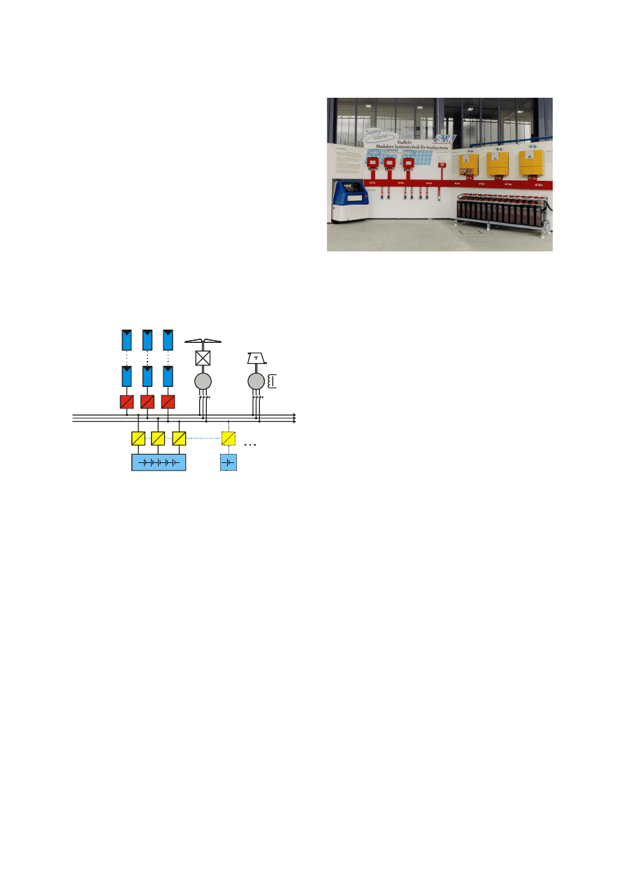
three phase systems. Figure 8 shows the structure of
a three phase island system in principle and Figure 9
the prototype of a three phase hybrid system in the
DeMoTec centre of ISET. First demonstration plants
will be built on the Greek island Kythnos [5].
generator
set
consumers
GS
=
~
=
~
=
~
=
~
=
~
=
~
=
~
photovoltaic
modules
wind
turbine
G
3~ / 400 V
PV-string-
inverter
(e.g. Sunny Boy)
battery inverter
Sunny Island
batteries
60 V
Figure 8: Example of the structure of a three phase
modular island network
5. PERSPECTIVES
Due to the modular conception of the battery
inverter, power ranges from 3.6 kW to 33 kW can be
achieved by the parallel connection of inverters in
single phase and three phase systems. Additionally it
is possible to extend existing systems after the unit
construction or to extend single phase systems to
three phase systems. The application of this modular
battery inverter will reduce planning and system
costs for hybrid island grids.
The use of stand alone hybrid grid systems on the
basis of the battery inverters "Sunny Island" will also
enable a power supply in remote areas without mains
connection for the first time and therefore will reduce
the consumption of resources for the electric energy
production. So even lower social classes have
access to electricity for lighting, household and for
small workshops.
The consistent modularity of this new system
oriented concept allows a commercial use and self
supporting retail structures (leasing of the systems or
sale of the produced electricity), since the
components (battery inverter, batteries, diesel sets...)
do not have to be adapted for individual applications,
but are universally applicable.
Figure 9: Prototype of a three-phase hybrid system
in the DeMoTec centre of ISET
The ISET and SMA thank the German Federal
Ministry BMWi for the promotion of the project
"modular battery inverter: development of a battery
for the modular system technology in PV systems"
and the European Commission for the promotion of
the projects “PV-MODE”, “MORE” an “HYBRIX”.
REFERENCES
[1]
W. Kleinkauf, J.Sachau: Components for
Modular Expandable and Adaptable PV
Systems, 12th European PV Solar Energy
Conference, Amsterdam, April 1994
[2]
B. Burger, G. Cramer, A. Engler, B. Kansteiner,
P. Zacharias: Battery Inverter for Modularly-
Structured PV Power Supply Systems, 2nd
World Conference and Exhibition on
Photovoltaic Solar Energy Conversion, Hofburg
Congress Center, Vienna, Austria, July 1998
[3]
B. Burger, P. Zacharias, G. Cramer, W.
Kleinkauf: Hybrid Systems – Easy in
Configuration and Application, 16
th
European
Photovoltaic Solar Energy Conference and
Exhibition, Glasgow, United Kingdom, May 2000
[4]
M. Rothert, B. Willer: Möglichkeiten und
Grenzen der Ladezstandsbestimmung von
Bleibatterien in PV-Anlagen, 13. Symposium
Photovoltaische Solarenergie, Kloster
Banz/Staffelstein, 1998
[5]
P. Strauss, D. Mayer, C. Trousseau, S.
Tselepis, P. Romanos, F. Raptis, J. Reekers, M.
Ibrahim, R.-P. Wurtz, F. Perez-Spiess, M.
Bächler: Stand-Alone AC PV Systems and
Micro Grids with New Standard Power
Components, 16
th
European Photovoltaic Solar
Energy Conference and Exhibition, Glasgow,
United Kingdom, May 2000
Wyszukiwarka
Podobne podstrony:
Adaptive fuzzy control for uninterruptible power supply with three phase PWM inverter
Adaptive fuzzy control for uninterruptible power supply with three phase PWM inverter
Control and Power Supply for Resistance Spot Welding (RSW)
A Composite Pwm Method Of Three Phase Voltage Source Inverter For High Power Applications
Performance Improvements in an arc welding power supply based on resonant inverters (1)
(ebook electronics) Schematics Power Regulated Power Supply for CB & Ham Radio
An Igbt Inverter For Interfacing Small Scale Wind Generators To Single Phase Distributed Power Gener
Layout guidlines for switching power supply
Power Supply For Oled Driver
A PIC CONTROLLER FOR GRID CONNECTED PV SYSTEM USING A FPGA BASED INVERTER
Computer Pc Power Supply Repair for print
A Composite Pwm Method Of Three Phase Voltage Source Inverter For High Power Applications
Convert Computer ATX Power Supply to Lab Power Supply
Conducted EMI in PWM Inverter for Household Electric Appliance
[US 2005] 6864611 Synchronous generator for service in wind power plants, as well as a wind power
Inverter For Domestic Fuel Cell Applications
Jvc Power Supply Description And Trouble Shooting Procedure
więcej podobnych podstron