
IEEE TRANSACTIONS ON INDUSTRIAL INFORMATICS, VOL. 6, NO. 1, FEBRUARY 2010
73
Design the Remote Control System With the
Time-Delay Estimator and the
Adaptive Smith Predictor
Chien-Liang Lai and Pau-Lo Hsu, Member, IEEE
Abstract—In real applications, a remote control system is gener-
ally an integration of different networks consisting of a commer-
cial network for message transmission and an industrial network
to control the remote hardware through a communication gateway.
Since the induced time-delay in network control system (NCS) may
cause system instability, this paper proposes a remote NCS struc-
ture by implementing the adaptive Smith predictor with an on-
line time-delay estimator. As the delay in a commercial network
Ethernet is significantly time-varying depending on the number of
end-users, the delay is estimated in this paper by processing the
online measurement of the round-trip time (RTT) between the ap-
plication layers of the server and the client. The adaptive Smith
predictor control scheme is developed by directly applying the es-
timated time-delay. To prove the feasibility of the proposed remote
control system, the developed design has been applied to an AC
400 W servo motor tested from a 15 km distance. The experimental
results indicate that the significantly improved stability and mo-
tion accuracy can be reliably achieved by applying the proposed
approach.
Index Terms—Adaptive Smith predictor, controller area net-
work (CAN), Ethernet, networked control system (NCS), remote
control, time-delay.
I. I
NTRODUCTION
D
UE to the rapid development of data communication net-
work technologies in the Internet, real-time networked
control applications have increasingly gained attention. These
applications include teleoperation, remote mobile robots, and
factory automation, which are organized by wiring connections
among control system devices through network resources. The
popularity is also because of the fact that network applications
can be conveniently and systematically maintained in industry
[1]. One of the newly developed technologies in modern indus-
trial applications is the networked control system (NCS), which
has potential applications simply by interconnecting all sensors,
actuators, and controllers through networks [2]. The introduc-
tion of network technologies provides easy maintenance and
expandability for the control system design, but it also leads
to problems of time-delay, data dropout, and package collision.
Manuscript received December 31, 2008; revised October 24, 2009 and
November 19, 2009. First published December 18, 2009; current version
published February 05, 2010. This work was supported by the National Science
Council, Taiwan, R.O.C., under Grant NSC 98-2218-E-009-005. Paper no.
TII-08-12-0237.
The authors are with the Department of Electrical and Control Engineering,
National Chiao-Tung University, Hsinchu, 300, Taiwan, R.O.C. (e-mail:
plhsu@mail.nctu.edu.tw).
Digital Object Identifier 10.1109/TII.2009.2037917
Network scheduling has been studied to cope with these prob-
lems. Another concern is that NCS performance may become
unstable because the network delay is stochastic in nature, and
it is difficult to directly apply linear delay-time system analysis.
The total network-induced delay, both in the controller and ac-
tuator, may present a bound or random format depending on the
network protocols and seriously degrade the NCS performance.
Recently, the use of NCS to deal with band-limited channels,
time delays, and packet loss has been widely studied, mainly for
the improvement of communication protocols and controller
design [3]–[5]. With proper communication protocols, the
enhancement of transmission technology provides guaranteed
quality-of-service (QoS) for real-time applications [6]. A suffi-
cient condition ensuring robust stability of NCS was presented
in [7]. Tatikonda et al. formulated a linear discrete-time con-
trol problem with a noiseless digital communication link and
provided the role of information patterns and control policy
knowledge [8]. Zai et al. used average dwell time for discrete
switched systems to obtain conditions so that the stability of
NCS is guaranteed [9]. Network-induced delay is one of the
most important issues of NCS, and different methodologies
have been proposed to deal with the delay effect within the
process control loop. Considering both known and constant
process delays with noise, a minimum variance control law
[10] and a step-by-step tuning procedure [11] were developed
separately to attain PI achievable performance for linear SISO
time-delayed processes. Furthermore, extension of [10] was
then developed to MIMO system [12]. A solution of minimum
variance control law for the linear time-variant processes has
been derived in the transfer function form [13]. Lian et al.
identified several components of the time-delay of network
protocols and control dynamics, and determined an accept-
able working range of the sampling period in NCS [14]. The
feedback gain of a memoryless controller and the maximum
allowable delay can be derived by solving a set of linear matrix
inequalities [15]. A design method of time-delayed control
systems based on the concept of network disturbance and the
communication disturbance observer (CDOB) without the
knowledge of the delay-time model was proposed in [16].
Most of the above-mentioned research results are limited to
constant or less time-varying delays of which are not true in
real network environments. In this paper, time-based time-delay
analysis of the NCS is provided to explain how it affects network
systems. By applying the proposed adaptive Smith predictor
based on the online time-delay estimation, satisfactory control
performance of NCS can be obtained even as the time-delay in-
creases significantly over integrated commercial and industrial
1551-3203/$26.00 © 2009 IEEE
Authorized licensed use limited to: IEEE Xplore. Downloaded on May 13,2010 at 11:49:31 UTC from IEEE Xplore. Restrictions apply.
74
IEEE TRANSACTIONS ON INDUSTRIAL INFORMATICS, VOL. 6, NO. 1, FEBRUARY 2010
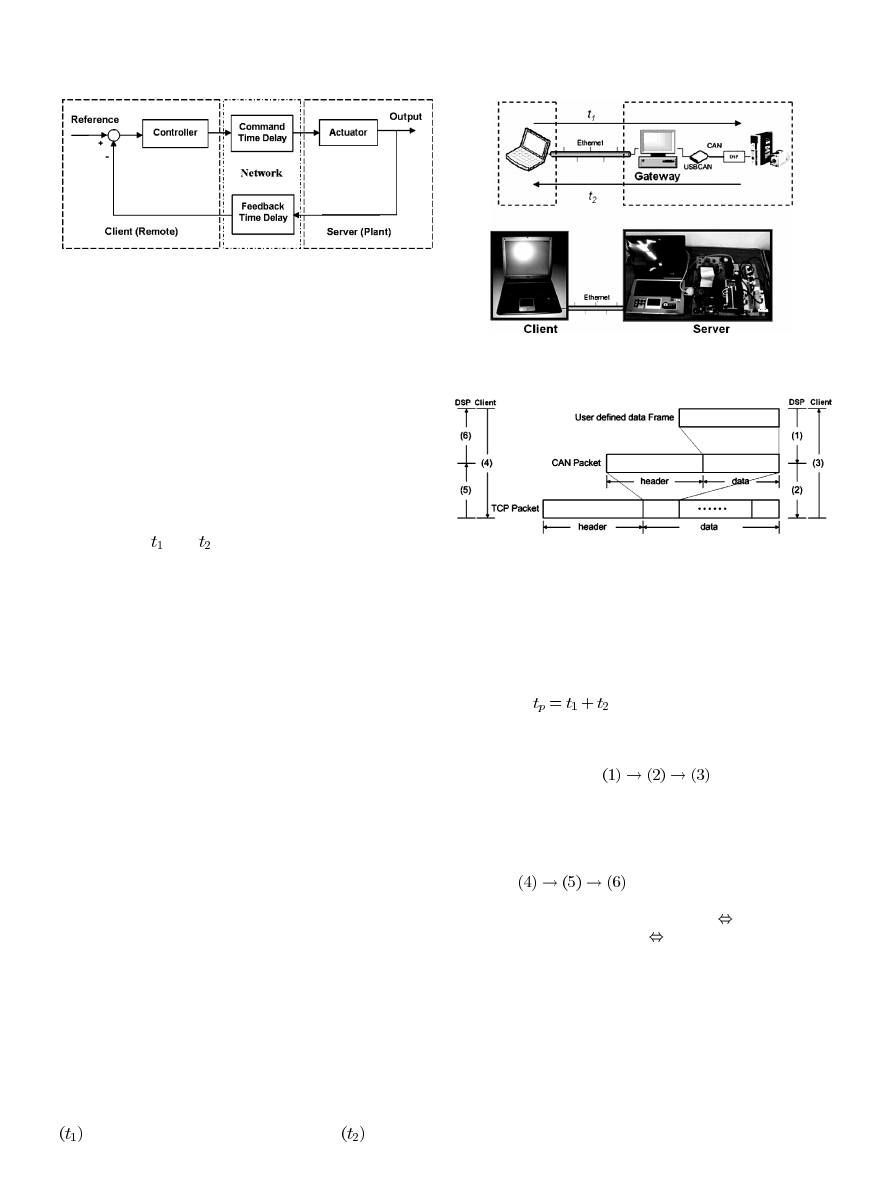
Fig. 1. The NCS block diagram.
networks. The proposed NCS has been applied to a remote con-
trol system for an AC 400 W servo motor tested from a 15 km
distance to verify the proposed design.
This paper is organized as follows: Section II introduces
the NCS and the time-delay. Section III presents a real-time
estimation algorithm for the delay time in a network, and
an adaptive Smith predictor control scheme is proposed.
Section IV discusses the main results, and conclusions are
obtained in Section V.
II. NCS
AND
T
IME
-D
ELAY
M
EASUREMENT
The general NCS in the closed-loop model is shown in
Fig. 1, where
and
are the time-delays induced in the
network structure for the controller-to-actuator direction and
the sensor-to-controller direction, respectively. Basically, the
induced network delay varies according to the network load,
scheduling policies, number of nodes, and different protocols.
Network-delay systems are also different from general linear
time-delay systems in that there is an assumption that the delay
is constant or bounded. The NCS with time-varying character-
istics makes modeling and design for NCS more difficult. The
total time-delay can be categorized into three classes, based on
the parts where they occur, namely, the server node, the network
channel, and the client node. The time-delay at the server node
is the preprocessing time, which is the sum of the computation
time, the encoding time, the waiting time, the total queuing
time, and the blocking time. The network time-delay includes
the total transmission time of a message and its propagation
delay, which depends on the message size, data rate, and the
length of the network cable. The time-delay at the client node
is the postprocessing time, as shown in Fig. 1.
Fig. 2 shows the structure of the present remote NCS, which
includes the remote controller in the client and the server for
the remote-controlled device. The client and the server com-
municate with each other from a distance through the Ethernet
network. The server consists of two parts in the present experi-
mental setup. The first part is the gateway, which is implemented
on a computer with the USBCAN designed to communicate
between the Ethernet network and the CAN bus. The second
part is the remote local servo motor controller implemented on
TI F2812 DSP with a speed-control mode. The data commu-
nication protocol adopts transmission control protocol (TCP)
to construct the position loop for the remote control [17]. As
shown in Fig. 2, the communication network can be modeled as
the time-delay on the forward-command direction for actuators
and on the feedback direction for sensors
. Therefore,
Fig. 2. The experimental setup.
Fig. 3. The package transition diagram.
the network time-delay includes both the total transmission time
of a message and the transformation time of the package from
CAN data to Ethernet data. The processing time of the trans-
formation is relatively small compared with the transmission
time-delay. The total time-delay (round-trip time, RTT) can be
expressed as
, as shown in Fig. 2.
When data have to be transmitted to the remote client from
the local hardware DSP, the type and the transition data in the
data frame should be set up in advance, as shown in Fig. 3. By
following the procedure
, the message of the
local DSP can be transmitted to a remote client. When data have
to be transmitted to the client from the DSP, both the type and
the transition data in the data frame should be set up on the CAN
package. The CAN message is then included in the TCP package
transmitted to the server through the Ethernet by following the
procedure
.
The network delay time for the present experiments includes
the following cases: (1) NCTU Laboratory
NCTU Labora-
tory and (2) NCTU Laboratory
Hukuo (the two places are
15 km apart). The computer used for this network transmission
had the following specifications: Intel
®
Pentium CPU 1.60 GHz,
496 MB of RAM, Realtek RTL8139/810x Family Fast Ethernet
NIC Network Card, and the Windows XP Professional Version
2002 OS with SP2. The local area network (LAN) was used,
and the time-delay exists between the application layer of the
client and the server. In addition, the RTT measurement is cru-
cial in the provision of accurate delay measurements periodi-
cally. Technically, the Windows Forms Timer component in the
operating system is single threaded, and it is limited to an ac-
curacy of 55 ms. A higher resolution performance counter of
Authorized licensed use limited to: IEEE Xplore. Downloaded on May 13,2010 at 11:49:31 UTC from IEEE Xplore. Restrictions apply.
LAI AND HSU: DESIGN THE REMOTE CONTROL SYSTEM WITH THE TIME-DELAY ESTIMATOR AND THE ADAPTIVE SMITH PREDICTOR
75
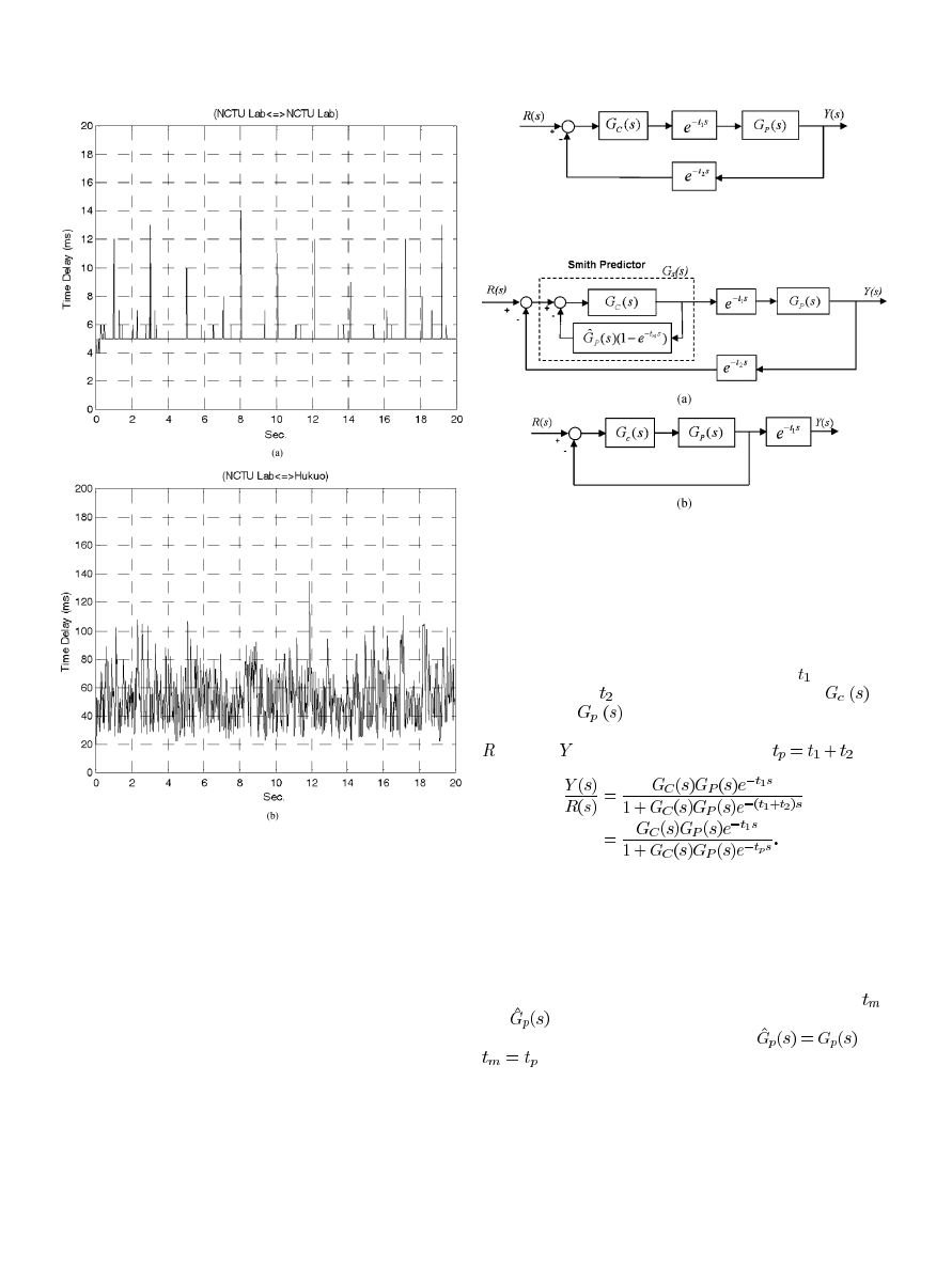
Fig. 4. Measured Internet delays: (a) NCTU Laboratory
, NCTU Laboratory.
(b) NCTU Laboratory
, Hukuo.
the DSP timer with accuracy of 1 ms is used to measure net-
work delay between the server and the client. We measured the
time-delay from two different clients within the NCTU Labora-
tory, and from two different clients located each in the NCTU
Laboratory and Hukuo.
The delay time in the integrated Ethernet and the CAN bus
transmitted with a 20 ms sampling period was measured, with
results shown in Fig. 4. Because the transmission speed of the
intranet is at 100 Mbps with a relatively short route within
the NCTU Laboratory, only a very small delay time (around
3–15 ms) was recorded. From the NCTU Laboratory to Hukuo,
the delay time increases since the transmission procedure takes
more routes and switches. The experimental results indicate
that the application environment greatly affects the induced
delay time in NCS. Moreover, as distance increases, the delay
time of a network increases as more nodes are involved.
Fig. 5. The simplified block diagram of NCS.
Fig. 6. The system with the Smith predictor. (a) The original system. (b) The
equivalent system.
III. A
DAPTIVE
S
MITH
P
REDICTOR
The communication network can be modeled as the time-
delay on the forward direction for the actuator and on the feed-
back direction for the sensor. As shown in Fig. 5,
is the com-
mand delay time,
is the feedback delay time, and
is
the controller.
denotes the transfer function of the real
plant without the delay time. The transfer function from input
to output
is obtained as follows: (where
)
(1)
The known delayed process can be effectively handled by ap-
plying the Smith predictor if information of its delay is known
and constant [18]. Since the delay time in the Internet can be
measured between sending and receiving a packet, the equiv-
alent block diagram in a closed-loop NCS can be well com-
pensated by applying the Smith predictor, as shown in Fig. 6.
The nominal delay time adopted for the Smith predictor is
,
and
is the nominal model for the system. With an accu-
rate model of the plant and the time-delay,
and
, the block diagram in Fig. 6(a) can be simplified into
Fig. 6(b) with a pure time-delay term by applying the Smith
predictor. In this paper, the delay time is estimated from the
measured RTT with a real-time technique for implementing the
Smith predictor [19]. To cope with significant variation in the
delay time due to the network transmission, an adaptive design
method is proposed for the present remote control systems with
the integration of the Smith predictor, the PI controller, and the
time-delay estimation. This is shown in Fig. 7.
Authorized licensed use limited to: IEEE Xplore. Downloaded on May 13,2010 at 11:49:31 UTC from IEEE Xplore. Restrictions apply.
76
IEEE TRANSACTIONS ON INDUSTRIAL INFORMATICS, VOL. 6, NO. 1, FEBRUARY 2010
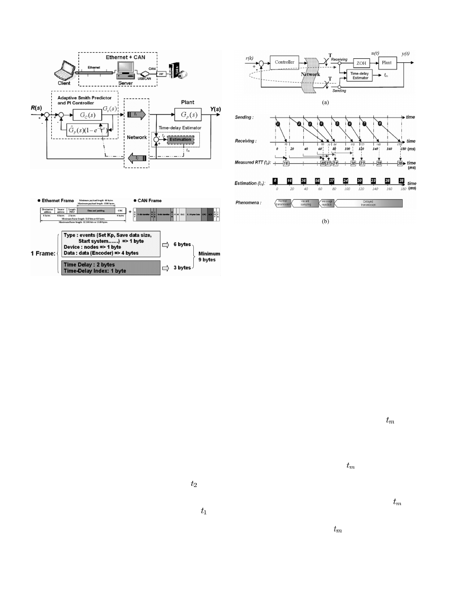
Fig. 7. The block diagram of the adaptive Smith predictor with a PI controller.
Fig. 8. The CAN data frame in the proposed NCS for measuring RTT.
A. Online Estimation of the Delay Time
A method for estimating the delay time within the Internet
for the NCS architecture with a combination of the time-driven
and the event-driven processes is proposed in this paper. The
designed control algorithm was realized on the present network
by integrating both the Ethernet and the CAN bus with a
high-integrity serial data communications bus between those
devices. Technically, the standard CAN bus transmits only 8
bytes per frame; however, the minimum data length to realize
the proposed RTT measurement will take 9 bytes. A program-
ming method wherein messages will be divided into two parts
and each of them will be sent at each half sampling period
through the CAN network is proposed here. This is shown in
Fig. 8.
To illustrate the estimation of the induced network time-delay
from the measurement of RTT, the NCS transmission is shown
in Fig. 9. At the beginning of the sampling period, the clock-
driven sensor node transmits the sampling data to the controller
node. By assuming the sensor-to-controller delay as
for this
setup, the event-driven controller node uses the sensor data to
compute the control signal and then transmits it to the actuator
node. By assuming the controller-to-actuator delay as
, the
time-driven transmission is applied. The measurement of RTT
was adopted due to its easy implementation and the fact that no
clock synchronization is required since all computations are op-
erating in the same device. The RTT measurement is crucial in
periodically providing accurate delay measurements. A higher
resolution performance counter of the DSP timer is used to mea-
sure the network delay between the client and the server, as
Fig. 9. The illustrative example for the time-delay estimation. (a) The archi-
tecture of the proposed RTT measurement. (b) The four transmitted models for
the RTT and the time-delay estimation.
shown in Fig. 5. An example of message transmission based on a
20 ms sampling time is shown in Fig. 9(b). If a time-delay is less
than one sampling time, its delay effect on the control perfor-
mance is one sample delay and the first frame is in normal trans-
mission. The second frame is sent 20 ms later, and a packet is
received at 68 ms. Accordingly, the corresponding RTT is 48 ms
and there is no data frame received at the 40 and 60 ms sam-
pling times. This phenomenon is called vacant sampling [20].
Two data messages (2 and 3) arrived in the same sampling pe-
riod, and only the most recent data message is accepted while all
previous data are discarded. This is referred to as message rejec-
tion [20], [21]. For messages 4–8, all data arrived sequentially at
each sampling point, although the exact receiving timing varied
slightly. This occurrence is similar to delayed transmission. To
summarize, the delay time of NCS can be modeled using four
phenomena: normal transmission, vacant sampling, message re-
jection, and delayed transmission. The time-delay
adopted
for the adaptive Smith predictor is estimated from the measured
RTT with the following rules.
1) Normal transmission: When the time-delay is less than one
sampling period, its delay effect is negligible and the mea-
sured RTT is directly adopted as
.
2) Vacant sampling: When the data message is not received
before occurrence of the next sampling period, the previous
measured RTT added with one sampling period is recog-
nized as the current estimation of the delay time
.
3) Message rejection: When more than two data messages ar-
rive at the same sampling period, only the most recently
measured RTT is adopted as
and all the previous mea-
sured data are discarded.
4) Delayed transmission: The continuously measured RTT
is the estimated time-delay and directly adopted for the
adaptive Smith predictor to compensate for the time-delay
effect.
Authorized licensed use limited to: IEEE Xplore. Downloaded on May 13,2010 at 11:49:31 UTC from IEEE Xplore. Restrictions apply.
LAI AND HSU: DESIGN THE REMOTE CONTROL SYSTEM WITH THE TIME-DELAY ESTIMATOR AND THE ADAPTIVE SMITH PREDICTOR
77
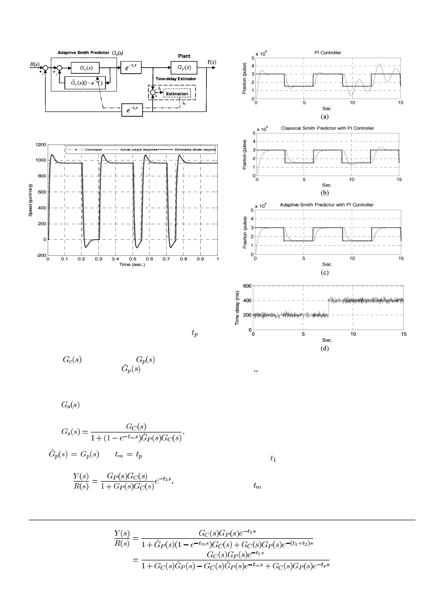
Fig. 10. The control structure with the adaptive Smith predictor.
Fig. 11. Experimental results for system identification.
B. Adaptive Smith Predictor Design
Fig. 10 shows the block diagram of the network control
system with a time-delay estimator. The total time of the
command delay time and the feedback delay time is
, as il-
lustrated in Fig. 5. The Smith predictor is proposed as a control
structure to compensate for the delay time [18], [19]. As shown
in Fig. 10,
is the controller,
denotes the transfer
function of the real plant and
is the nominal model of
the system without the delay time. The transfer function for
the system as the adaptive Smith predictor involved is obtained
using equation (2) shown at the bottom of the page. In Fig. 10,
the part of
with the dotted line is the Smith predictor. Its
transfer function is simplified as follows:
When
and
, then the (2) simply be-
comes
(3)
Fig. 12. Simulation results for: (a) the PI controller; (b) the classical Smith
predictor (
t = 200 ms) with PI controller; and (c) the adaptive Smith predictor
with PI controller.
Equation (3) shows that the complicated transfer function of
the delay time will become two simple parts. One part is the
transfer function of the system without the delay time, and the
other is the pure simple delay. The equivalent block diagram of
(3) is also shown in Fig. 6(b). Here, the system presents the same
closed-loop system but only with the pure command (forward)
delay time as
. In this case, the adaptive Smith predictor is
proposed here the network delay is significant and the nominal
value of the delay time is adopted directly from the estimated
value as
.
(2)
Authorized licensed use limited to: IEEE Xplore. Downloaded on May 13,2010 at 11:49:31 UTC from IEEE Xplore. Restrictions apply.
78
IEEE TRANSACTIONS ON INDUSTRIAL INFORMATICS, VOL. 6, NO. 1, FEBRUARY 2010
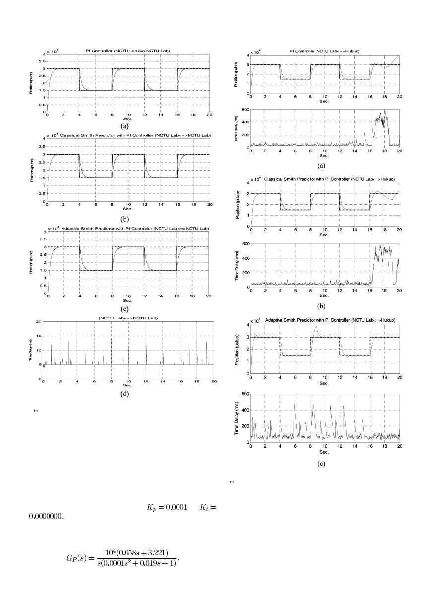
Fig. 13. Experimental results for: (a) PI controller; (b) classical Smith predictor
(
t = 5 ms) with PI controller; and (c) adaptive Smith predictor with PI con-
troller (NCTU Laboratory
, NCTU Laboratory).
IV. M
AIN
R
ESULTS
The experimental setup was implemented to verify the time-
delay effect induced by the network. To apply a remote control
system on an AC 400 W servo motor, both the proposed adaptive
Smith predictor control method and the online time- delay esti-
mation algorithm were implemented efficiently on the DSP mi-
crocontroller. The position control loop is located on the remote/
client site. Due to the high gain of the encoder with 10000 P/R, co-
efficients of the PI controller are tuned as
and
. The system identification result of the speed-control
loop from the pseudorandom binary signal (PRBS) response for
the present AC permanent magnet synchronous motor is shown in
Fig. 11. The open-loop position control is obtained as follows:
Fig. 14. Experimental results for: (a) PI controller; (b) classical Smith predictor
(
t
= 46 ms) with PI controller; and (c) adaptive Smith predictor with PI
controller (NCTU Laboratory
, Hukuo).
Different controllers were tested according to following
setups: 1) with the PI controller only; 2) the classical Smith
predictor with the PI controller with a fixed delay time; and
3) the adaptive Smith predictor with the PI controller. For the
client, the sampling time of the experiments was 20 ms with
a square-wave command, where the upper/lower command of
30000/15000 pulses was provided. As the delay time increases,
Authorized licensed use limited to: IEEE Xplore. Downloaded on May 13,2010 at 11:49:31 UTC from IEEE Xplore. Restrictions apply.

LAI AND HSU: DESIGN THE REMOTE CONTROL SYSTEM WITH THE TIME-DELAY ESTIMATOR AND THE ADAPTIVE SMITH PREDICTOR
79
Fig. 15. Experimental results for the adaptive Smith predictor (with the zero
initial value).
Fig. 16. Experimental results for the adaptive Smith predictor (with an initial
time-delay).
as shown in Fig. 12(d), simulation results indicate that control
performance of the proposed adaptive Smith predictor presents
much better performance compared with the PI controller with
the classical Smith predictor as shown in Fig. 12(a) and (b).
Experiments were also set up with different sites to test the pro-
posed design. The delay time within the NCTU Laboratory was
much smaller than the sampling time, so the time-delay effect
was neglected, as shown in Fig. 13(d), and experimental results
indicate that the control performance for different controllers is
similar. As experiments tested between the NCTU Laboratory
and Hukou with 15 km distance in addition with massive
download data from multiple users at 16 seconds to share the
limited network bandwidth, experimental results indicate that
the time-delay accordingly increases to a certain level and
the PI controller with a fixed-delay Smith predictor becomes
unsuitable, as shown in Fig. 14(a) and (b). However, even with
dramatically varied network-induced time-delay, the proposed
adaptive Smith predictor still renders improved performance,
as shown in Fig. 14(c). Furthermore, compared with three
continuous responses of the proposed adaptive Smith predictor
without considering the initial value as shown in Fig. 15, the
proposed design with proper initial delay time renders much
improved performance, as shown in Fig. 16.
V. C
ONCLUSION
In this paper, the remote control system has been realized on
the integrated Ethernet and CAN bus. By applying the adap-
tive Smith predictor with an online estimator for the delay time,
the significantly induced time-delay effect on the NCS has been
successfully reduced. The experimental results are summarized
as follows:
1) Because the present network integrates both the Ethernet
and the CAN bus, the transmitted message is restricted
by the CAN frame since its data length is limited to
8 bytes per frame only. For real-time applications, the
present measurement of RTT requires 9 bytes for the data
length. Therefore, in this paper, an algorithm is proposed
by sending the measurement of each frame at the half
sampling period to achieve online estimation of the delay
time of the proposed NCS
2) The adaptive Smith predictor is adopted with the online
estimated time-delay to achieve improved performance of
NCS, and the significant time-varying delay effect mainly
on the Ethernet is thus reduced. The experimental results
on an AC servo motor over 15 km away also indicate that
the proposed approach leads to significantly improved sta-
bility and control performance.
3) The present remote controller applying the adaptive Smith
predictor may present a larger overshoot because an initial
estimation error may exist. By measuring the time-delay
in advance as the nominal value, better performance can
be obtained.
Although the remote control system with a general NCS can
be stable for most of the time as the delay is bounded, the system
stability is not guaranteed especially when a serious time-delay
occurs. To prove the feasibility of our proposed approach, the
adaptive Smith predictor has been successfully applied to NCS
under significantly time-varying delay time to control an AC
servo motor.
R
EFERENCES
[1] G. Kaplan, “Ethernet’s winning ways,” IEEE Spectrum, vol. 38, pp.
113–115, Jan. 2001.
[2] F. L. Lian, J. R. Moyne, and D. M. Tilbury, “Performance evaluation of
control networks: Ethernet control net and device net,” IEEE Control
Syst. Mag.
, pp. 66–83, Feb. 2001.
[3] J. Baillieul and P. J. Antsaklis, “Control and communication challenges
in networked real-time systems,” Proc. IEEE, vol. 95, pp. 9–28, Jan.
2007.
[4] J. P. Hespanha, P. Naghshtabrizi, and Y. Xu, “A survey of recent results
in networked control systems,” Proc. IEEE, vol. 95, no. 1, pp. 138–161,
Jan. 2007.
[5] S. Zampieri, “Trends in networked control systems,” in Proc. 17th
IFAC
, Seoul, Korea, Jul. 6–11, 2008, pp. 2886–2893.
[6] M. Grenier and N. Navet, “Fine-tuning MAC-Level protocols for opti-
mized real-time QoS,” IEEE Trans. Ind. Inform., vol. 4, no. 1, pp. 6–15,
Feb. 2008.
[7] C. H. Chen, C. L. Lin, and T. S. Hwang, “Stability of networked control
systems with time-varying delays,” IEEE Commun. Lett., vol. 11, no.
3, pp. 270–272, Mar. 2007.
[8] S. Tatikonda and S. Mitter, “Control under communication con-
straints,” IEEE Trans. Autom. Control, vol. 49, pp. 1056–1068, July
2004.
[9] G. Zhai, B. Hu, K. Yasuda, and A. N. Michel, “Qualitative analysis of
discrete-time switched systems,” in Proc. ACC’02, Jun. 2002, vol. 3,
pp. 1880–1885.
[10] M. Jain and S. Lakshminarayanan, “A filter based approach for per-
formance assessment and enhancement of SISO control systems,” Ind.
Eng. Chem. Res.
, vol. 44, pp. 8260–8276, 2005.
Authorized licensed use limited to: IEEE Xplore. Downloaded on May 13,2010 at 11:49:31 UTC from IEEE Xplore. Restrictions apply.

80
IEEE TRANSACTIONS ON INDUSTRIAL INFORMATICS, VOL. 6, NO. 1, FEBRUARY 2010
[11] D. B. Goradia, S. Lakshminarayanan, and G. P. Rangaiah, “Attainment
of PI achievable performance for linear SISO processes with dead time
by iterative tuning,” Can. J. Chem. Eng., vol. 83, pp. 723–736, Aug.
2005.
[12] M. Jain and S. Lakshminarayanan, “Estimating performance enhance-
ment with alternate control strategies for multiloop control systems,”
Chem. Eng. Sci.
, vol. 62, pp. 4644–4658, 2007.
[13] B. Huang, “Minimum variance control and performance assessment of
time variant processes,” J. Process Control, vol. 12, pp. 707–719, Apr.
2002.
[14] F. L. Lian, J. R. Moyne, and D. Tilbury, “Network design consideration
for distributed control systems,” IEEE Trans. Control Syst. Technol.,
vol. 10, no. 2, pp. 297–307, 2002.
[15] D. Yue, Q. L. Han, and C. Peng, “State feedback controller design of
networked control systems,” IEEE Trans. Circuits Syst., vol. 51, pp.
640–644, Nov. 2004.
[16] N. Kenji and O. Kouhei, “A design method of communication distur-
bance observer for time delay compensation,” IEEE Trans. Ind. In-
form.
, vol. 4, no. 3, pp. 185–197, Aug. 2008.
[17] C. W. Cheng, C. L. Lai, B. C. Wang, and P. L. Hsu, “The time-delay ef-
fect of multiple-network systems in NCS.,” in Proc. SICE Annu. Conf.
2007 1C11-4
, Takamatsu, Japan, Sep. 18–20, 2007.
[18] C. Peng, D. Yue, and J. Sun, “The study of Smith prediction controller
in NCS based on time-delay identification,” in Proc. Int. Conf. Control,
Autom., Robot., Vision
, Dec. 2002, pp. 1644–1648.
[19] P. Sourdille and A. O’wyer, “A new modified Smith predictor design,”
in Proc. 1st Int. Symp. Inf. Commun. Technol., Sep. 2003, vol. 49, pp.
385–390.
[20] Y. Halevi and A. Ray, “Integrated communication and control system
networks: Part I—Analysis,” J. Dynamic Syst., Measure., Control, vol.
110, pp. 367–373, 1998.
[21] M. Y. Chow and Y. Tipsuwan, “Network-based control systems: A
tutorial,” in Proc. 27th Annu. Confl IEEE Indl Electrol Socl, 2001, pp.
1593–1602.
Chien-Liang Lai
received the B.S. degree from the
National Taiwan University of Science and Tech-
nology, Taipei, in 1996 and the M.S. degree from the
National Chung Hsing University, Taichung, Taiwan,
in 1998, both in electrical engineering. Currently,
he is working towards the Ph.D. degree at National
Chiao Tung University, Hsinchu, Taiwan.
He was a Senior Engineer at the Hannstar Display
Corporation during 2000–2003. In 2003, he joined
the SIC Electronic Corporation as a Deputy Manager.
From 2004 to 2005, he served as a Senior Engineer of
AU Optronics (AUO) Corporation. His research interests include remote mon-
itor and networked control systems.
Pau-Lo Hsu
(M’91) received the B.S. degree
from the National Cheng Kung University, Tainan,
Taiwan, the M.S. degree from the University of
Delaware, Newark, and the Ph.D. degree from
the University of Wisconsin–Madison, in 1978,
1984, and 1987, respectively, all in mechanical
engineering.
He was with San-Yang (Honda) Industry during
1980–1981 and Sandvik (Taiwan) during 1981–1982.
In 1988, he joined the Department of Electrical and
Control Engineering, National Chiao Tung Univer-
sity, Hsinchu, Taiwan, R.O.C., as an Associate Professor. He has been a Pro-
fessor since 1995. During 1998–2000, he served as the Chairman of the depart-
ment. His research interests include CNC motion control, servo systems, diag-
nostic systems, and network control systems.
Authorized licensed use limited to: IEEE Xplore. Downloaded on May 13,2010 at 11:49:31 UTC from IEEE Xplore. Restrictions apply.
Wyszukiwarka
Podobne podstrony:
H Infinity State Feedback Control for a Class of Networked Cascade Control Systems With Uncertain De
The Discrete Time Control of a Three Phase 4 Wire PWM Inverter with Variable DC Link Voltage and Bat
The Discrete Time Control of a Three Phase 4 Wire PWM Inverter with Variable DC Link Voltage and Bat
The best Affiliate Program with Life time commision
How to build a USB device with PIC 18F4550 or 18F2550 (and the microchip CDC firmware)
Correspondence of Roosevelt and Truman with Stalin on Lend Lease and Other Aid to the Soviet Union
rx 2b remote controller with five function
Designing the capital structure
A NEW CATALOGUE OF THE CERAMBYCIDAE (COLEOPTERA) OF ISRAEL WITH NOTES ON THEIR DISTRIBUTION AND HOST
The globalization of economies and trade intensification lead companies to communicate with consumer
KOLE The arrow of time in cosmology and statistical physics (termodynamics, reductionism)
Design of a System for Real Time Worm Detection
Rebels for the System Virus writers, general intellect, cyberpunk and criminal capitalism
Control System Toolbox
10 Emission control system
07 emission control system
10 Engine Control System
więcej podobnych podstron