http://www.erico.com/productPrint.asp?productid=2238
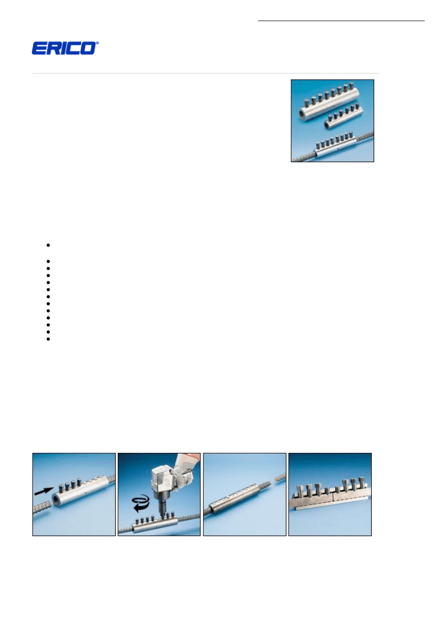
LENTON® LOCK Mechanical Rebar Splicing System
LENTON
®
LOCK, an in-situ rebar splice from ERICO
®
, requires no bar-end preparation. It is ideal
for repair, new construction, or retrofit applications. The LENTON LOCK coupler features
patented gripping technology that provides for the development of full rebar strength and improved
overall structural integrity in tension, compression, stress-reversal and dynamic applications. This
unique design allows the coupler to be smaller and more streamlined. This innovative mechanical
rebar splice is designed to specification for use in column splicing, bridge applications, piling,
splicing to protruding dowels cast in concrete, closure pours, beams, chimney construction and
other demanding splicing applications.
LENTON LOCK couplers meet or exceed major international building codes and Department of
Transportation (DOT) requirements, including Caltrans Ultimate Splice requirement. The Ultimate
Splice classification requires the connector to force a fracture into the parent reinforcing bar
remote of the rebar connector.
LENTON LOCK couplers allow for easy and simple field installation since no bar-end preparation, sawing or swaging is necessary.
The couplers can be installed with just a standard wrench or an impact wrench depending on coupler size. The bolt heads will shear off
when proper installation tightness has been reached, which allows for completely visual inspection.
The completed connection performs similar to a continuous piece of rebar. In testing, the couplers demonstrated less than 0.004 in
(0.10 mm) of slip.
FEATURES
Meets or exceeds major international building code and Department of Transportation requirements, including Caltrans
Ultimate Splice requirement, IBC
®
, UBC
®
and ACI
®
318 Type 2, DIN 1045 and BS8110
Is designed to break the reinforcing bar remote from the rebar connector
Uses standard rebar; requires no bar-end preparation such as sawing or swaging – ideal for in-situ splices
Is smaller than other bolted splices currently available
Performs like a continuous piece of rebar
Works in repair, bent bar, retrofit precast and new construction applications
Meets slip criteria of less than 0.004 in (0.10 mm)
Provides superior fatigue performance
Works with a variety of standard US and international rebar grades
Installs quickly and easily using simple hand tools – does not require special skilled labor
Allows for simple visual inspection
Splices will do a one-step transition to the next smallest size (e.g. LL28B1 will connnect 25 mm rebar to 28 mm rebar)
Product Performance
LENTON LOCK meets or exceeds:
IBC Type 1 & 2
UBC Type 1 & 2
ACI 318 Type 1 & 2
DIN 1045
CALTRANS Ultimate
BS8110
APPLICATIONS
LENTON LOCK is designed to break the reinforcing bar remote from the rebar connector.
MORE INFORMATION
Simple 1-2-3 Installation:
1.Insert the LENTON
LOCK coupler over
reinforcing bar.
2.Tighten bolts from
the center to the end
to secure onto the
first reinforcing bar.
(Air impact wrench
shown*)
3.Repeat steps 1 & 2
with the second
reinforcing bar on
the other side of
the coupler.
This cutaway shows
LENTON LOCK’s patented
gripping technology on the inside
of the coupler and patented round
bolts on the outer edges of the
coupler.
http://www.erico.com/productPrint.asp?productid=2238
LENTON LOCK, with
its patented round end
bolts, is designed to
break the reinforcing bar
remote from the rebar
connector in accordance
with Ultimate Splice
requirements.
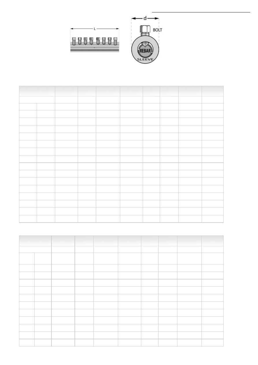
Side view of coupler
*Contact ERICO for a list of recommended impact wrenches and sockets.
Product Specifications, Imperial
Rebar
Designation
Coupler
Part
Number
Length
(L)
Outside
Diameter
(d)
Inside
Diameter
Weight
Socket
Size
Average
Torque All
Bolts
Number
of Bolts
Inch-Lb
Canada
in
in
in
lb
in
ft-lb
-
-
LL12B1
5.0
1.1
0.6
1.2
1/2
150
6
#4
10 M
LL12B1
5.0
1.1
0.6
1.2
1/2
150
6
-
-
LL16B1
6.3
1.4
0.7
2.1
1/2
150
6
#5
15 M
LL16B1
6.3
1.4
0.7
2.1
1/2
150
6
-
-
LL20B1
7.5
1.6
0.9
3.1
1/2
150
8
#6
20 M
LL20B1
7.5
1.6
0.9
3.1
1/2
150
8
#7
-
LL22B1
8.7
1.9
1.1
5.2
5/8
350
8
#8
25 M
LL25B1
10.0
2.1
1.2
7.4
5/8
350
8
#9
30 M
LL28B1
11.3
2.4
1.3
10.2
5/8
350
10
-
-
LL28B1
11.3
2.4
1.3
10.2
5/8
350
10
#10
-
LL32B1
12.7
2.6
1.5
13.1
13/16
500
8
-
-
LL36B1
14.1
2.8
1.7
17.3
13/16
550
10
#11
35 M
LL36B1
14.1
2.8
1.7
17.3
13/16
550
10
-
-
LL40B1
15.7
3.1
1.9
24.0
13/16
580
12
-
-
LL40B1
15.7
3.1
1.9
24.0
13/16
580
12
Product Specifications, Metric
Rebar
Designation
Coupler
Part
Number
Length
(L)
Outside
Diameter
(d)
Inside
Diameter
Weight
Socket
Size
Average
Torque All
Bolts
Number
of Bolts
Metric
Soft
Metric
mm
mm
mm
kg
mm
N-m
10
10
LL12B1
127
29
15
0.6
13
205
6
12
13
LL12B1
127
29
15
0.6
13
205
6
14
-
LL16B1
159
35
19
0.9
13
205
6
16
16
LL16B1
159
35
19
0.9
13
205
6
18
-
LL20B1
191
41
24
1.4
13
205
8
20
19
LL20B1
191
41
24
1.4
13
205
8
22
22
LL22B1
222
48
28
2.3
16
475
8
25
25
LL25B1
254
54
30
3.4
16
475
8
28
29
LL28B1
287
60
34
4.6
16
475
10
30
-
LL28B1
287
60
34
4.6
16
475
10
32
32
LL32B1
323
65
38
5.9
21
680
8

http://www.erico.com/productPrint.asp?productid=2238
34
-
LL36B1
358
72
43
7.9
21
750
10
36
36
LL36B1
358
72
43
7.9
21
750
10
38
-
LL40B1
400
80
47
10.9
21
790
12
40
-
LL40B1
400
80
47
10.9
21
790
12
NOTES
Dimensions shown in chart are typical. Bolt length may vary after the bolt heads are sheared off.
When using air impact wrench, check the air pressure, torque rating and air flow requirements before starting installations.
Refer to installation instructions for information on DIN slip or Caltrans Ultimate Splice requirements.
Refer to complete installation instructions provided with the product or available at www.erico.com before commencing
installation.
Patent no. 7,107,735 / 7,093,402. Additional patents in other countries.
ACI is a registered trademark of the American Concrete Institute. IBC is a registered trademark of the International Code Council. UBC
is a registered trademark of the International Conference of Building Officials.
Copyright © 2008 ERICO International Corporation.
http://www.erico.com/productPrint.asp?productid=2078
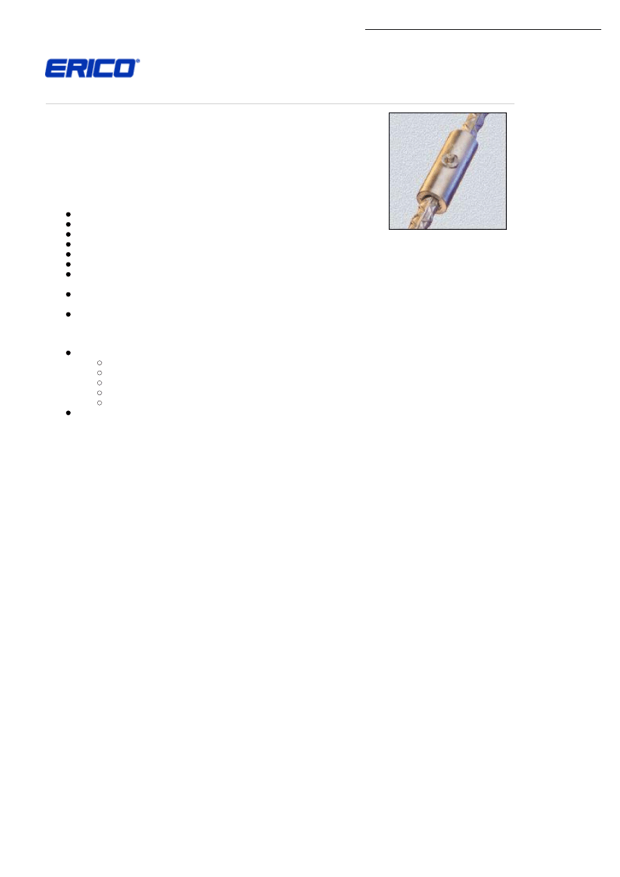
CADWELD® Rebar
For the most demanding applications, the CADWELD® mechanical splicing system has
extremely high tensile performance. It is the only rebar splicing system that has been used
in over 200 Nuclear Power Plant projects throughout the world.
The CADWELD rebar splice is a mechanical butt splice (a metal filled splice, not a welded
splice) that produces a joint with basically the same mechanical properties as those of an
unspliced bar. CADWELD rebar is very suitable for in-situ splicing applications.
FEATURES
No special skills required
Works on all grades of steel with deformations
Can be visually inspected
No special bar end preparation needed
Designed to meet or exceed many major Building Code requirements
World’s most tested mechanical splice - over 25,000 actual tensile tests
Consistently develops minimum ultimate strength of the rebar (150% of yield on grade 60 bars according to ASTM
A615)
Requires hand-held equipment only (no heavy hydraulic non-electrical equipment), thus can deal with minimum bar
spacing
Retrofit and repair with short dowels
APPLICATIONS
The primary usage for CADWELD is related to critical structures requiring high safety margins such as:
Blast resistant facilities
Pressure vessel applications
Seismic resistance
Nuclear reactor containment structures
In-situ splicing applications
It is also excellent for joining circumferential bars
MORE INFORMATION
How CADWELD Works
The CADWELD splice utilizes an internally grooved sleeve working in conjuction with the rebar deformations. Load is transferred
from the rebar to the sleeve via CADWELD filler material. The finished connection develops strength and consistency without
equal in the industry.
How to Specify
By Name:
For full tensile strength specify - CADWELD Full Tensile Strength Splices.
By Generic Description:
On jobs requiring a generic description (usually government specifications prohibit the use of a proprietary name) use the
following description:
Type of splice required is sleeve with ferrous filler material to achieve...
How to Install CADWELD T-Series Horizontal Splice
1. Ensure you have the following components to make one splice:
Expendable Components required for each splice
• Sleeve Only
• CADWELD Ferrous Filler Material
• Guide Video Tape
• Pouring Basin Ceramic
• Crucible Ceramic
• Disk
• Packing Material
• Spacer
Non-expendable Hardware required to make all splices
• Crucible Frame
• Crucible Extension
• Crucible Cover
• Flint Igniter
• End Alignment Fitting (x2)
• Horizontal Pouring Basin Frame
• Horizontal Packing Clamp
Components provided with kits on prorated basis
• Pouring Basin
• Crucible

http://www.erico.com/productPrint.asp?productid=2078
2. Clean the rebar of surplus particles and make sure it is free of moisture by pre-heating it, add spacer and position (centre) the
sleeve over the rebar join.
3. Position the End Alignment Fittings over the rebar at each end of the sleeve. Insert the Packing Material around the rebar
inside the Alignment Fitting.
4. Attach the Horizontal Packing Clamp to the rebar.
5. Insert Guide Tube and then Pouring Basin Ceramic into the Sleeve outlet. Position the Horizontal Pouring Basin Frame over
the sleeve.
6. Preheat all graphite components to make sure they are moisture free before installation
7. Position the Pouring Basin on top of the t-bar inserted in the Bottom Support Clamp (align with Pouring Basin Ceramic) and
place crucible on top of the Pouring.
8. Insert Crucible Ceramic and then Disk
9. Pour CADWELD Ferrous Filler Material into the Crucible.
10. Position the Crucible Extension over the Crucible and cover with Crucible Cover.
11. Stand back and ignite with Flint Igniter. Allow a few seconds to cool before removing apparatus.
Please note that this is a guide to making a CADWELD splice only. Full instructions will be supplied at time of product
purchase.
How to Install - CADWELD T-Series Vertical Splice
1. Ensure you have the following components to make one splice:
Expendable Components required for each splice
• Sleeve Only
• CADWELD Ferrous Filler Material
• Guide Video Tape
• Pouring Basin Ceramic
• Crucible Ceramic
• Disk
• Packing Material
• Spacer
Non-expendable Hardware required to make all splices
• Crucible Frame
• Crucible Extension
• Crucible Cover
• Flint Igniter
• End Alignment Fitting (x2)
• Vertical Pouring Basin Frame
• Bottom Support Clamp
Components provided with kits on prorated basis
• Pouring Basin
• Crucible
2. Clean the rebar of surplus particles, add spacer and position (centre) the sleeve over the rebar join.
3. Attach the Bottom Support Clamp beneath the sleeve allowing sufficient room for the End Alignment Fitting - attach the End
Alignment Fittings onto the rebar at each end of the sleeve.
4. Insert the Packing Material around the rebar inside each End Alignment Fitting.
5. Insert Guide Tube and then Pouring Basin Ceramic into the Sleeve outlet.
6. Position the Pouring Basin on top of the t-bar inserted in the Bottom Support Clamp (align with Pouring Basin Ceramic) and
place crucible on top of the Pouring Basin.
7. Attach the Crucible Frame to the Crucible and attach the Vertical Pouring Basin Frame to the Crucible Frame, Bottom Support
Clamp, sleeve and rebar.
8. Insert Crucible Ceramic and Disk (usually supplied as one unit)
9. Pour CADWELD Ferrous Filler Material into the Crucible.
10. Position the Crucible Extension over the Crucible and cover with Crucible Cover.
11. Stand back and ignite with Flint Igniter. Allow a few seconds to cool before removing apparatus.
Note that this is a guide to making a vertical splice only. Full instructions will be supplied at time of product purchase.
Copyright © 2008 ERICO International Corporation.
Document Outline
Wyszukiwarka
Podobne podstrony:
Gramsch and Meier BAR 2508 libre
Texas Rangers 5607 The Bar Girl, the Battle and the Bar D
Herbs for Sports Performance, Energy and Recovery Guide to Optimal Sports Nutrition
MA Skills Com Mount And Hamme
Magnetic Treatment of Water and its application to agriculture
Seven Signs You’re?out to? Fired and Seven Ways to?al with It
How to cut Mini and Micro SIM to Nano SIM
Glucocorticoids alter fever and IL 6 responses to psychological
Derrida, Jacques Speech and Writing according to Hegel
EU and the Balkans The Long and Winding Road to Membership
The main press station is installed in the start shaft and?justed as to direction
Adding Scanlines and Black Borders to Text
SHSBC383 THE PRECLEAR AND GETTING AUDITING TO WORK
Guidance for ambulance personnel on decisions and situations related to out of hospital CPR
Guidance for ambulance personnel on decisions and situations related to out-of-hospital CPR, MEDYCYN
Money and Happiness A Guide to Living the Good Life
Ask questions and give answers?cording to the information you have got
więcej podobnych podstron