
HIP CLADDING OF TOOLS
W. Theisen
Ruhr-University of Bochum
Institute of Materials
Materials Technology
D-44780 Bochum,Germany
Abstract
HIP cladding is a coating method to be used in the production of efficient
tools. Aside from the traditional PM steel grades MMC hard phase/metal
powder compounds are recommendable coating materials. When it comes to
resist abrasive wear the latter are successfully employed if they contain up to
30 vol% of hard phases sized 100 µm. Pin-on-disk tests show an increased
wear resistance of up to two orders of magnitude if the powder particle size
is adjusted such that a hard phase dispersion is obtained. A favorable cost-
benefit ratio can be achieved using titanium carbides that form during the
compacting process due to the purposeful utilization of diffusion phenomena
arising between the hard particle and metal matrix.
The composite layers require a heat treatment that is matched to the sub-
strate and coating material. The dissimilar transformation behavior that might
lead to cracking hazards can be appropriately counteracted by vacuum furnace
treatment and possibly applying hot bath techniques.
Keywords:
HIP cladding, Metal Matrix Composites (MMC), powder metallurgy, hot
isostatic pressing, wear resistant material, hard phase, metal matrix, heat
treatment, thick coatings, abrasive wear
INTRODUCTION
Tools that have to be wear resistant may either be fabricated of high-
alloyed materials as solid bodies or if emphasis is on cost efficiency as a
coated component. If the focus is on abrasion as primary wear mechanism
hard alloys with hard phases (carbides, borides, nitrides) embedded in a
metal matrix on Fe, Ni or Co basis have proven their worth [1, 2]. The
947

948
6TH INTERNATIONAL TOOLING CONFERENCE
properties depend in the first place on the volume fraction, the size, shape
and distribution as well as mechanical properties of the hard phases and
metal matrix. Hard alloys contain 20 to 60 vol% of hard phases, which
is in the range between tool steels and cutting materials (e.g. hard metals,
Cermets). Whereas highly stressed tool edges are partially protected by
build-up welding or laser surface treatments powder metallurgical manu-
facturing processes allow large areas of components and tools to be coated
by means of hot isostatic pressing (HIP cladding). Applying current HIP
parameters (1150℃, 100 MPa) the particles of an atomized steel powder
if necessary with the addition of hard phases are compacted into a solid
material and at the same time bonded to a suitable substrate. Powder met-
allurgy vs. melting metallurgy offers some decisive advantages. While the
microstructure of melted hard alloys is formed based on the chemical com-
position and solidification sequence the PM technology allows hard phase
type and size to be almost freely selected. Moreover, PM coatings enable
the crackfree formation of thick coatings containing more hard phases with
the homogeneity of the microstructure and bond to the substrate being much
better than in build-up welding or thermal spraying techniques.
COATING MATERIALS
HIP cladding counts among the diffusion welding processes. Starting
point is usually a solid substrate that is coated with a layer of compacted pow-
der. As coating material high-alloy gas-atomized steel powders are available
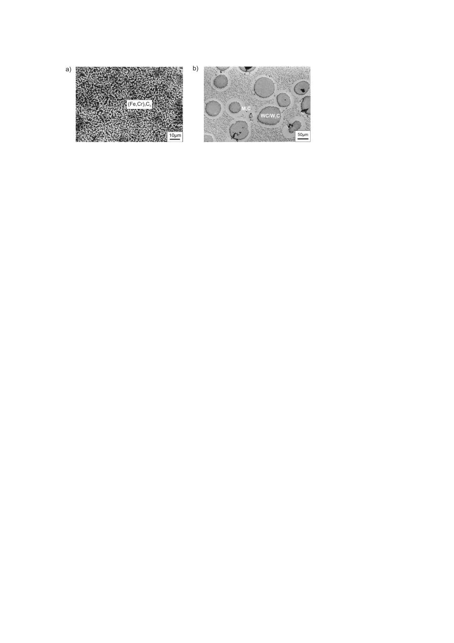
(Table 1) as used for the manufacture of rods and bars out of which cold,
hot and high-speed steel tools are made, see Fig. 1a. They contain fine hard
phases precipitating from the melt when the powder particles cool down in
the atomizing tower. In the event of highly abrasive wear hard phase/metal
powder mixtures are needed, see Fig. 1b. They should be counted to the
group of metal matrix composites (MMC). As metal matrix component the
steel powders listed in Table 2 are suitable due to their broad range of desir-
able material properties. As hard particles in MMC the metallic hard phases
of significance have been listed in Table 3 with a number of properties im-
portant for the bond [3].
The microstructure of the MMC is depending on the interdiffusion of el-
ements arising during hot compaction as well as by the particle size ratio of
both powder components. For manufacturing reasons the powder compo-
nents are not in thermodynamic equilibrium but they are approaching this

HIP Cladding of Tools
949
Table 1.
Selected gas atomized powders for PM-coatings
Designation
Cr
Mo
V
W
Si
C
B
Co
Ni
Fe
Ni-4
7,5
-
-
-
3,5
0,3
-
-
bal.
2
Ni-6
15
-
-
-
4,3
0,8
1,8
-
bal.
4
Co-12
29
-
-
8
1,4
1,9
3,1
bal.
-
-
Co-6
28
-
-
4
-
1,1
-
bal.
-
-
1.2380
13
1,1
4
-
0,4
2,3
-
-
-
bal.
1.3344
4,2
5
3,1
6,4
-
1,3
-
-
-
bal.
ASP 60
4
7
6,5
6,5
0,4
2,3
-
10,5
-
bal.
CPM10V
5,2
1,3
10
-
0,9
2,4
-
-
-
bal.
R124
20
1,3
10
0,8
-
3,6
-
-
-
bal.
Table 2.
Gas atomized matrix powders for MMC
T
A
α
[10
−6
K
−1
]
Hardness
[℃ ]
100
◦
600
◦
[HRC]
1.2714
56NiCrMoV7
830 - 870
12,2
14,3
35 – 56
1.2344
X40CrMoV5-1
1020 - 1060
11,5
13,0
50 – 56
1.2380
X230CrVMo13-4
1050 - 1150
12,2
13,9
54 – 63
1.3344
HS6-5-3
1150 - 1200
11,5
12,9
57 – 65
Table 3.
Physical properties of metallic hard phases in MMC
Hardness [HV
0
,05
]
Density [g/cm
3
]
α
[10
−6
K
−1
]
T
S
[℃ ]
(FeCr)
7
C
3
1400
6,92
10,3
1780
Cr
3
C
2
2300
6,68
10,6
1890
CrB
2
2250
5,58
10,5
2200
WC/W
2
C
2560
16,53
5,9
2800
VC
2900
5,41
7,3
2800
TiC
2950
4,93
8,3
3070
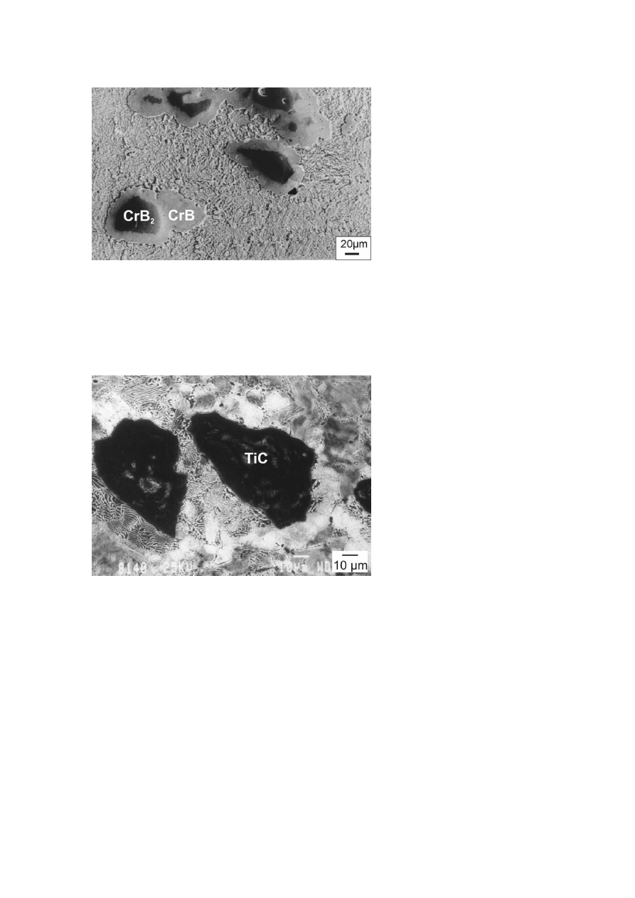
state as hot compaction takes place. Therefore, diffusion zones of varying
size were found to have formed in all examined materials around the hard
particles added. In Fig. 2 this is shown for CrB
2
in 56NiCrMoV7. As a
950
6TH INTERNATIONAL TOOLING CONFERENCE
(a) PM steel (1.2380)
(b) MMC (1.2380 + 30 vol% WC/W
2
C).
Figure 1.
Microstructure of coating materials.
result of an outward boron diffusion and a weak inward iron diffusion CrB
further outward M
3
B and M
23
(B,C)
6
, have formed around the CrB
2
core.
Although the resulting phases are softer than the CrB
2
core due to the de-
creasing boron content in outward direction, a hard particle proportion of 15
vol% added turns into a hard phase content of 30 vol% [4]. Similar effects
are noticeable when WC/W
2
C is used in steel matrixes. The diffusion zone
is of WC/W
2
C-type and further outward M
6
C, see Fig. 1b. The diffusion
rims as a rule have a positive influence on the adherence to the steel matrix
because the change in properties (E, H, α) at the interface between hard
phase and matrix is found to be moderate.
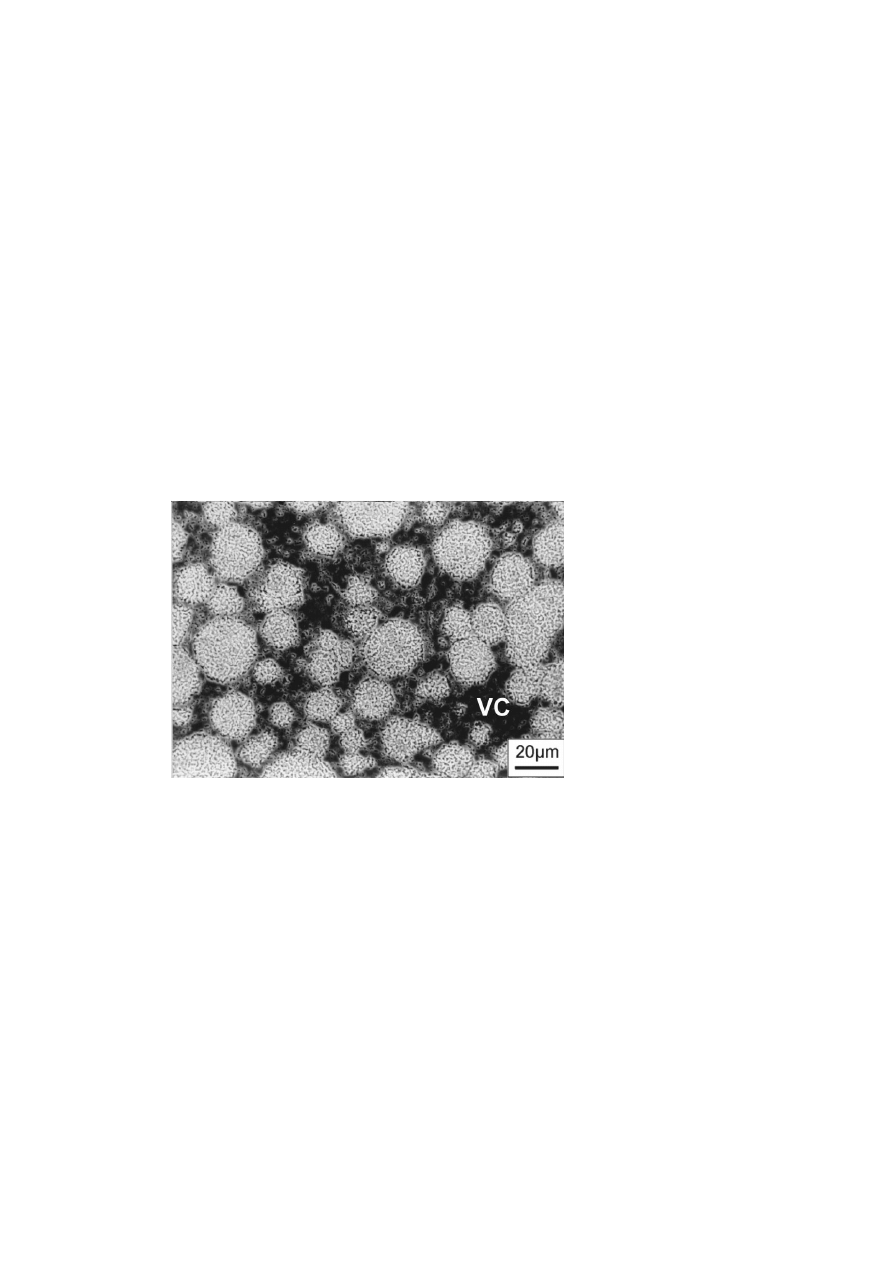
In a new manufacturing process the diffusion of carbon with phase trans-
formation in the solid state is purposefully used for the in-situ formation of
TiC [5]. During this process a crushed ferro-titanium powder of 100 µm
average grain size and in a proportion ranging between 10 and 30 vol% is
admixed to a steel powder of type 56NiCrMoV7. In addition, carbon in the
form of graphite powder is added to such an extent as is required to enable
the stoichiometric formation of TiC. During the HIP treatment TiC is formed
from outside-to-inside as a result of a carbon diffusion into the FeTi pow-
der with iron at the same time diffusing towards the outer case Fig. 3. The
transformation to TiC is not always complete since diffusion is prevented
due to growing TiC rims. For this reason, in-situ TiC is often dish-shaped
with small residual areas of Fe-Ti inside. Whereas due to the high cost of
the hard material the MMC powder is much more expensive than the pure
HIP Cladding of Tools
951
Figure 2.
Microstructure of a MMC (1.2714 < 100 µm + 15 vol% CrB
2
<
100 µm.)
matrix powder the price of MMC with in-situ TiC ranges below that of the
matrix powder since the ferro-titanium is inexpensive.
Figure 3.
Microstructure of a MMC (1.2714 < 100 µm + 10 vol% FeTi < 100 µm + C).
952
6TH INTERNATIONAL TOOLING CONFERENCE
Nevertheless, phase transformation may also entail negative effects. For
example, Cr
3
C
2
in steel matrixes is rather unstable and under standard HIP
conditions it is completely transformed to (FeCr)
7
C
3
. With a hardness of
1400 HV
0
,
05
M
7
C
3
is significantly softer than Cr
3
C
2
(2300 HV
0
,
05
) and does
not have the anticipated high wear resistance to minerals having a high quartz
content. The distribution of hard phases can be influenced via the grain size
ration and the proportion of the hard phase and matrix powder volume.
For example, if an MMC is produced from grade 1.2380 plus 30 vol% of
VC using commercially available grain sizes a network-like arrangement of
the VC carbides around the grains of the matrix powder will be attained,
Fig. 4.The fracture toughness of such a microstructure is extremely low
because of cracks propagating along the hard phase network without the
tough metal matrix being involved. This may lead to high wear rates due to
microfractures. Furthermore, as a result of the low ductility there is a more
pronounced crack hazard when quenching the material during hardening.
The use of hard material and matrix powders of comparable grain size will
result in a more favorable dispersed hard phase distribution as shown in
Fig. 1b for a MMC with pelletized fused tungsten carbide.
Figure 4.
Microstructure of a MMC (1.2380 < 200 µm + 30 vol% VC < 40 µm.)

HIP Cladding of Tools
953
WEAR RESISTANCE
Since the wear resistance of a material is system dependent it cannot
be viewed as a universally applicable property. If PM coatings are used
to withstand abrasion it is recommendable to thoroughly analyze the wear
system as well as the mechanisms and sub-mechanisms involved to enable
an optimized composite material to be developed on this basis. The role that
the hard phases play in this context is generally known. They can only be
effective if their hardness is higher than that of the groove-generating mineral
and if they are of sufficient volume and extend beyond the characteristic
groove width actually caused in a wear system [1, 2]. If this is not the case
they are practically of no use and are scored off together with the metal
matrix.
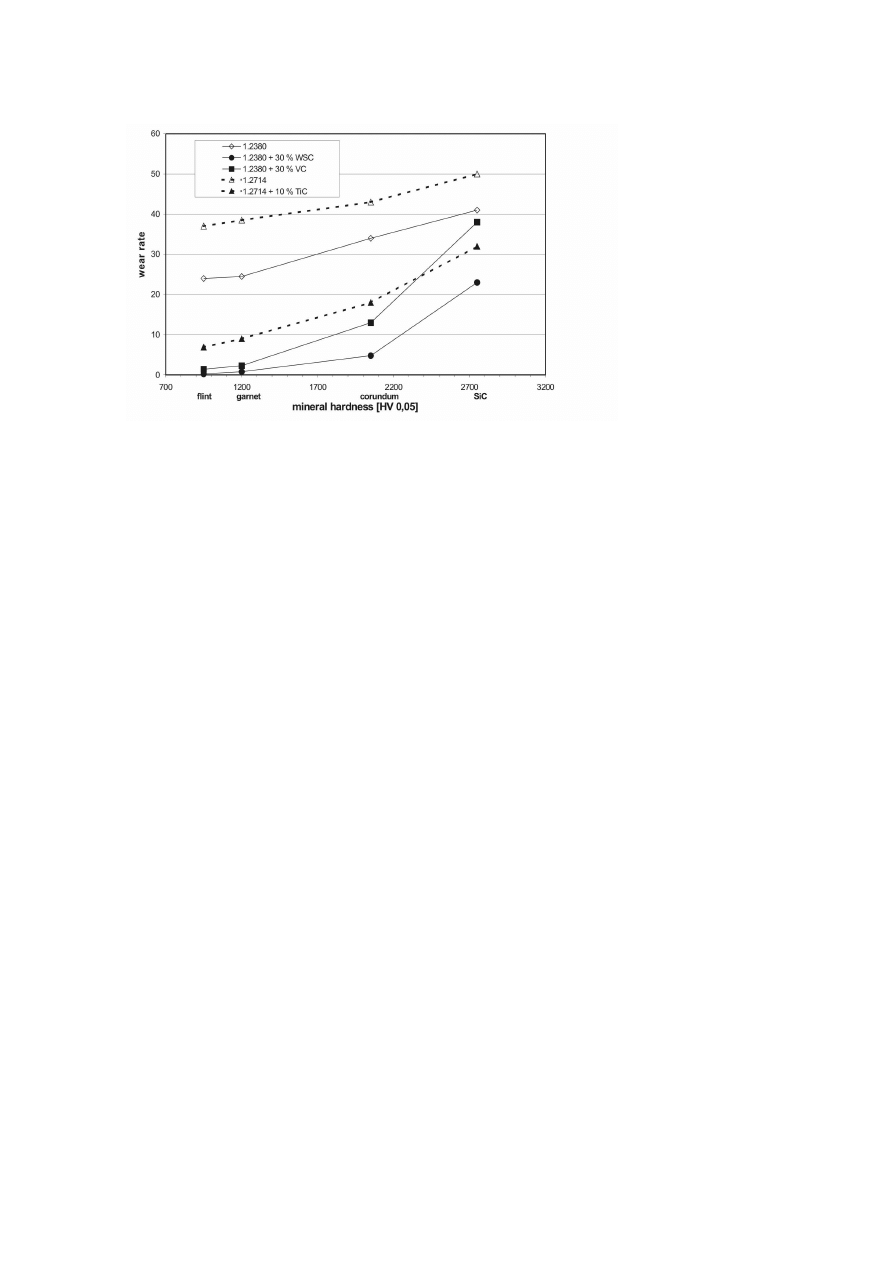
To classify wear resistant materials often a pin-on-disk test is employed in
which cylindrical pin samples are moved over various types of emery paper
(flint, garnet, Al
2
O
3
, SiC) without overlapping. Taking the weight losses
detected and based on length of the wear path, density and contact area a
dimensionless wear rate can be determined that has been shown as a function
of the abrasive hardness in Fig. 5 for some PM coatings.
Initially, a significant influence of the volume fraction of hard phases can
be noticed. The highest wear rates are found for PM steel grade 1.2714 that
does not contain hard phases. Slightly below is the curve characterizing
grade 1.2380 with approximately 23 vol% of fine hard phases, see Fig. 1a.
The addition of hard constituents no matter whether these are tungsten,
vanadium or titanium carbide results in a significantly lower wear rate. The
most pronounced effect is achieved with 30 vol% of fused tungsten carbides
(WSC) that lower the wear rate against flint on a pure steel matrix by a factor
of 100. An MMC based on 1.2380 with 30 vol% of VC shows results that
are only insignificantly inferior. A comparison between 1.2714 and 1.2714
with 10 vol% of TiC also indicates the wear reducing effect of hard phases
(here in-situ TiC). The wear rate reduction in this case however is not as
pronounced since only 10 vol% of hard constituents have been admixed.
MMC were particularly effective in withstanding grooving wear caused
by corundum and abrasives in the same hardness range. Obviously, the
harder carbides, WC/W
2
C, VC and TiC, improved the resistance to wear
considerably. As in case of flint the lowest wear rates against corundum
are detected on MMC consisting of 1.2380 and WC/W
2
C. Aside from its
954
6TH INTERNATIONAL TOOLING CONFERENCE
Figure 5.
Wear rates of PM-coatings as a function of mineral hardness.
high hardness fused tungsten carbide has an excellent fracture toughness that
adds to the material’s efficiency [6]. The wear reducing effect of the hard
phases is even apparent with SiC as wear-causing mineral since the MMC
wear rates are significantly below those of commercially available alloys.
Differences found between 1.2380 with tungsten carbide and with vanadium
carbide are due to the distribution of the hard phases, see Fig. 1b and Fig. 4.
As the abrasive hardness increases the hard-phase network of the VC has a
wear-increasing effect.
The wear rates with 1.2714 to which only 10 vol% in-situ TiC has been
added are found to be remarkably low.
MANUFACTURE
HIP CLADDING
Due to their steel matrices PM materials are especially suited as layers on
base materials made of steel [7]. HIP-cladding of steel powders to a solid
base material is performed by specialist companies. Using an appropriate

HIP Cladding of Tools
955
encapsulation technique layers can be clad on a substrate with low distortion
and very close to the final shape. Regarding the thickness of the coating layer
there is practically no limit. After the removal of the capsule by machining
the coated HIP component is subjected to a heat treatment. Such treatment
must be suitably performed to make sure the desired properties of the layers
and base material are attained.
HEAT TREATMENT
During HIP treatment particularly the base metal will suffer overheating
associated with grain growth. While in high-alloy coating materials this is
counteracted by fine carbides the grains in the low-alloy base material may
grow to millimeter size. Martensitic hardenable steels are normalized by the
α −γ −α transformation during the hardening treatment. If unalloyed steels
are clad with non-heat treated Ni- and Co- base alloys the HIP treatment
should be followed by normalizing since a grain coarsening will have a
substantial effect on the strength and toughness of the base material.
The desired properties of layer materials on iron basis are attained by
making use of a martensitic hardening process. Special emphasis in this
context is on the hardening temperature. If coatings are produced with high-
alloy steel powders such as 1.2380 or 1.3344 the austenitizing temperatures
are significantly above 1000℃. Since toughness and ductility aside from
strength is often recommended from the base material martensitic harden-
able steels are a good choice of substrate material. The problem of the
austenitizing temperature being approximately 200℃ lower than that of the
coating material may be circumvented by selecting an MMC matrix similar
to the base material (e.g. base material 1.2714 with MMC of CrB
2
in a
1.2714 matrix).
When heating up to austenitizing temperature care must be taken that
the temperature difference
∆T between case and core and thus the asso-
ciated thermal stresses remain small. As is customary with tool steels the
heating process must include holding stages for temperature balancing and
a correspondingly slow heat-up rate [8]. In most cases the holding period
at hardening temperature may be kept shorter than with materials made by
fusion metallurgical processes because the fine HIP microstructure can be
faster converted to a homogeneous austenite. As a result of their high con-
tent of hard phases MMCs have a lower thermal expansion coefficient than
the base material which may lead to thermal stresses arising in the boundary
956
6TH INTERNATIONAL TOOLING CONFERENCE
surface or interface. In this case a hard phase gradient in the coating has
brought about positive effects.
The rapid cooling of a PM composite material required for martensitic
transformation is to be viewed as particularly critical. Such a cooling pro-
cess should therefore only be just as quickly as is necessary since the risk
that cracks will develop in the hard layer increases with wall thickness but
most of all with the amount of hard phases present in the layer. Quenching
in hot bath will reduce the crack hazards. Sometimes the time- temperature-
transformation (TTT) diagrams of the steel matrix are no longer applicable
to the MMC. In particular if the diffusion reactions between hard phase and
matrix are strong the composition of the steel matrix and thus the transfor-
mation behavior may change. This can be viewed as positive if, for example,
carbon is transferred to the matrix shifting the pearlite-field towards longer
times. In this case cooling down can be more slow so that the risk of crack
formation is reduced.
Figure 6.
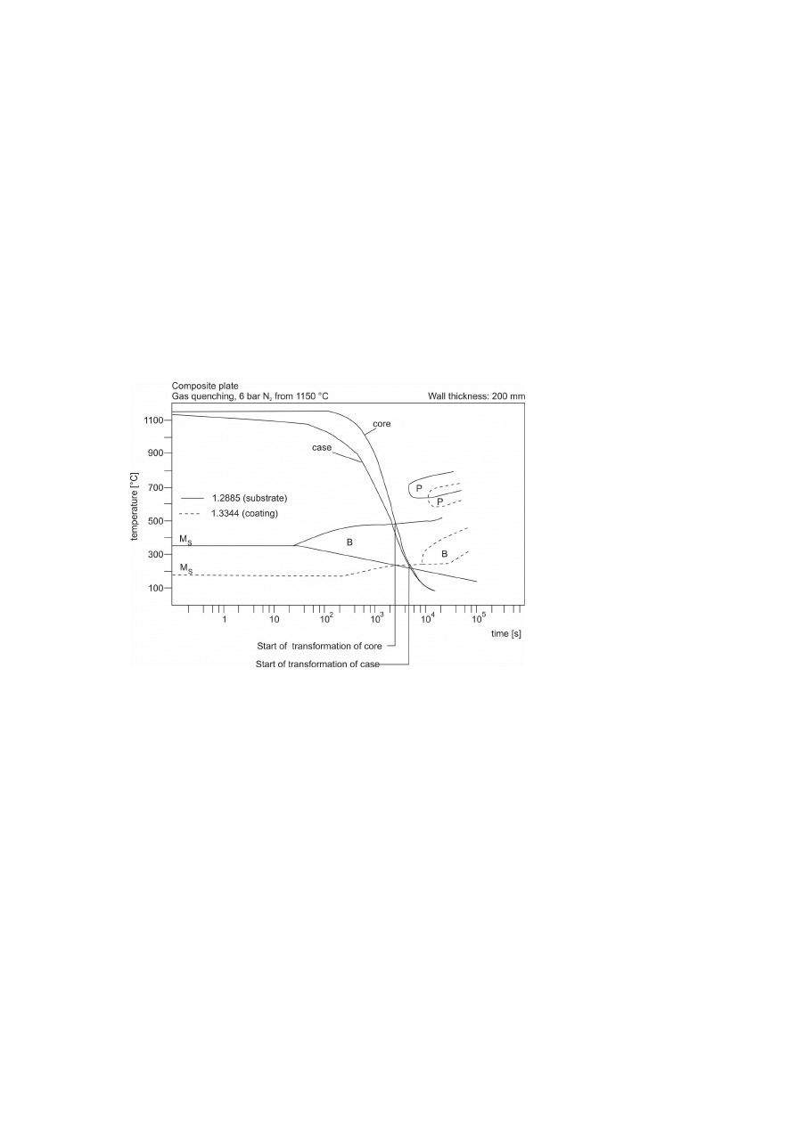
Cooling rates of a composite steel plate; Substrate: 1.2885 Coating: 1.3344.
Aside from cooling stresses also stresses caused by transformation have
to be considered. There is a risk that, due to the increase in volume caused
HIP Cladding of Tools
957
by the martensitic transformation of the core, the already martensitic case
is subjected to tensile stresses and fails. Ideally, base and layer materials
should therefore be selected such that the base material’s martensitic or
bainitic transformation takes place before the layer material is transformed.
For example, this is the case for a coating of 1.3344 steel grade on 1.2885 as
base material. Figure 6 shows the TTT-diagram for cooling down a 200 mm
thick composite sheet being quenched under the N
2
-pressure of 6 bar. Due to
the very pronounced bainite zone despite a slower cool-down rate the core is
transformed before the case has reached the martensitic starting temperature.
In this rather favorable case the transformation of the base material has
already been completed before martensite starts to form in the surface area.
With a continuous cooling down process this may not be achieved with other
materials. Also recommendable here is a hot bath treatment during which
the base material is transformed isothermally to upper bainite while the coat
or layer becomes martensitic only during subsequent cooling of the layer.
Suitable heat treatment processes especially for high-alloy coating mate-
rials are the salt bath and vacuum hardening methods. More flexibility is
offered by the vacuum furnace that enables all boundary conditions associ-
ated with the safe heat treatment of the composite to be satisfied.
Figure 7.
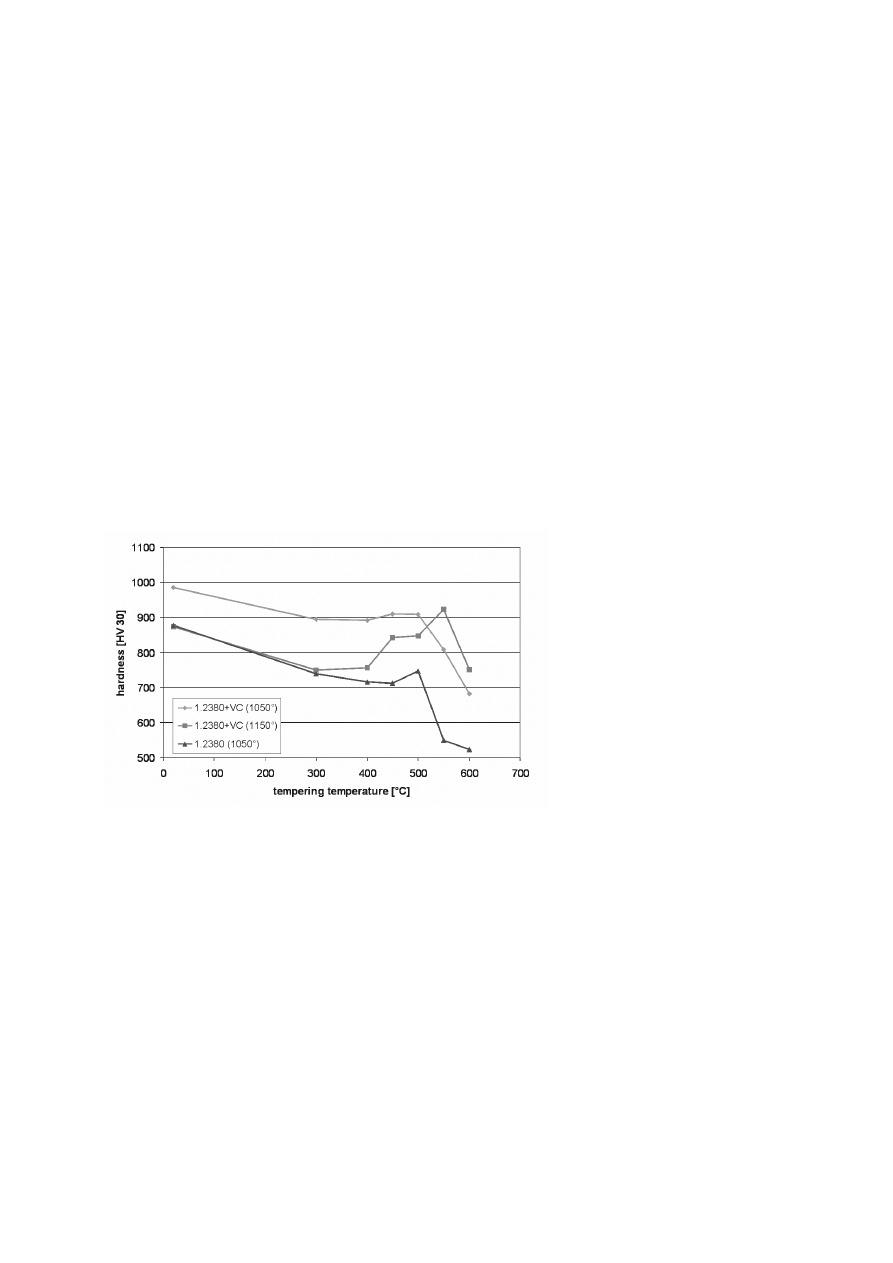
Hardness of PM-coatings as a function of tempering temperature.

958
6TH INTERNATIONAL TOOLING CONFERENCE
Hardening is followed by a tempering treatment by means of which the
hardness of the coating and the strength of the base material are suitably
adjusted. Favorable layer materials and metal matrices are those that show
a secondary hardness maximum allowing high tempering temperatures at
which any residual austenite is transformed to martensite leading to a high
surface hardness and a tough base material. Generally the macrohardness of
MMC is higher than that of the non-strengthened steel matrices, see Fig. 7.
At a high austenitizing temperature residual austenite causes a decrease
in quenchening hardness and alleviates cracking hazards. However, it is
transformed when tempering is carried out above the secondary hardness
maximum so that the maximum hardness can be reached.
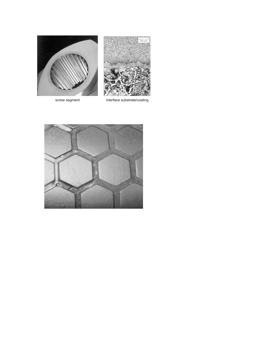
APPLICATIONS
Examples of successful applications have been found in the plastics pro-
cessing industry in recent years [9]. Here the outside of extrusion screws and
the respective extruder casing (inside) are provided with coating applied by
the HIP cladding process. Figure 8 shows a composite screw segment with
1.2380 outside and mild steel inside together with the microstructure of the
interface between both materials. Those composite components have be-
come the standard solution for twin screw extruders in the chemical industry
where hard additions to the polymer material caused remarkable wear. As
these tools must meet constantly increasing expectations the tool steels used
nowadays such as 1.2380, CPM10V or even corrosion resistant variants will
be substituted by wear and corrosion resistant MMC before long.
In the past few years PM claddings and coatings of tools used in mineral
and mining industry were successfully applied. Steel rings up to 1400 mm in
diameter and a total weight of 3,5 tons that were provided with HIP claddings,
were shrunk onto roller cores and employed as briquetting and crushing
rollers in the respective devices. In this context the surface provided with
hard hexagons of MMC as shown in Fig. 9 has proved its worth as roller
hardfacing material in high-pressure comminution roller presses [10, 11].
Only the HIP cladding technique enables such a two-component surface to
be produced that in comparison to conventional roller designs improves the
service life and at the same time increases the crushing efficiency by creating
better intake conditions and allowing higher admissible pressures.
It is to be assumed that the MMC’s outstanding resistance to wear as well
as the safe control of the HIP cladding technology will enable powder metal-
HIP Cladding of Tools
959
Figure 8.
Composite screw segment for a twin screw extruder (IMT-Bodycote).
Figure 9.
HEXADUR-coating on cement grinding rolls.
lurgical processes to be employed in tools in numerous fields of application
in the future.

960
6TH INTERNATIONAL TOOLING CONFERENCE
REFERENCES
[1] W. Theisen.: Bearbeiten verschleißbeständiger Legierungen aus werkstofftechnischer
Sicht, Fortschr. Ber. VDI-Reihe 2, Nr. 428, VDI-Verlag, Düsseldorf 1997
[2] H. Berns (ed.): Hartlegierungen und Hartverbundwerkstoffe, Springer Verlag, Berlin
1998
[3] W. Theisen: PM-Verbundwerkstoffe zum Verschleißschutz, HTM 55(2000)1
[4] A. Fischer, Ch. van Nguyen: New Boride Containing Hardenable Tool Materials for
Fe-Base PM-Composites with Graded Structures , Proc. Conf. PM 90 into the 1990’s,
Juli 1990, London, pp. 257-265
[5] H. Berns, B. Wewers: Development of an abrasion resistant steel composite with in situ
TiC particles, Wear 251 (2001) 1386-1395
[6] H. Berns, S.D. Franco: Effect of coarse hard particles in high temperature sliding abra-
sion of new metal matrix composites, Wear 203-204 (1997), 606-614
[7] C. Willems, W. Graf, W. Theisen: PM-HIP-Lösungen für Werkzeuge und Formen, Stahl
6 (1998) 11 pp. 38-40
[8] DIN 17 350: Werkzeugstähle – Technische Lieferbedingungen, Ergänzende Angaben
zur Wärmebehandlung, Beuth-Verlag, Berlin 1980
[9] E. Bayer, H. Seilstorfer: Werkstoffe für Verschleißschutz – Metallische Werkstoffe in
Menning (ed.) Verschleiß in der Kunstoffverarbeitung, source unknown
[10] W. Theisen: A Novel PM-Wear Protection Method to Meet High Comminution De-
mands, Wear 250 (2001) 54-58
[11] M. Schumacher, W. Theisen: HEXADUR- High Wear Resistant Rollers for High Pres-
sure Roller Presses, World Cement 3 (1998) 35-41
Wyszukiwarka
Podobne podstrony:
57 815 828 Prediction of Fatique Life of Cold Forging Tools by FE Simulation
Idiopathic chondrolysis of the hip
Guide for solubilization of membrane proteins and selecting tools for detergent removal
Periacetabular osteotomy for the treatment of dysplastic hip with Perthes like deformities
Effects of preoperative physiotherapy in hip osteoarthritis patients awaiting total hip replacement
MIS of the Hip and the Knee
Mechanical failure of external fixator during hip joint distraction for Perthes disease
COXARTHROSIS OF THE HIP AND THE KNEE
Hip hop in the age of empire Cape flat style Adam Haupt
Ed Seykota Of Technical Tools
Wear of HIP
tools of the mind a case study of implementing the Vygotskian
Machinability evaluation in hard turning of AISI 4340 steel with different cutting tools using st
list of parts and tools
Jaime Samms & Sarah Masters The Dreaming 1 Tools of Justice
więcej podobnych podstron