
* Corresponding author. Fax: #44-113-2424611.
E-mail address: j."sher@leeds.ac.uk (J. Fisher).
Biomaterials 22 (2001) 2191}2197
Wear of HIPed and non-HIPed alumina}alumina hip joints under
standard and severe simulator testing conditions
J.E. Nevelos , E. Ingham
, C. Doyle, A.B. Nevelos, J. Fisher *
Department of Mechanical Engineering, University of Leeds, Leeds LS2 9JT, UK
Department of Microbiology, University of Leeds, Leeds LS2 9JT, UK
Stryker International, Newbury, UK
Bradford Royal In
x
rmary, UK
Received 22 February 2000; accepted 23 October 2000
Abstract
Wear and the biological response to wear debris of arti"cial joints remain major concerns in total hip arthroplasty (THA). The
long}term e!ects of UHMWPE wear debris are well documented and these have led to interest in alternate bearing materials for
THA. Alumina ceramic}ceramic hip joints have been successfully used for more than 30 years with low wear and little incidence of
osteolysis. The most common wear pattern observed on retrieved components is an elliptical wear &stripe' on the heads and
a corresponding worn area on the cup with an approximated wear rate of 1}5 mm
pa. More severe wear has also occasionally
occurred, usually in association with an abnormal clinical history. Modern alumina}alumina THAs use an improved HIPed (hot
isostatically pressed) alumina ceramic-bearing material which may be more resistant to severe wear. Previous in vitro simulator
studies have not replicated in vivo wear rates or mechanisms. The aim of this study was to compare previous generation non-HIPed
alumina and modern HIPed alumina in a hip joint simulator under &normal' and &harsh' testing conditions. HIPed alumina was found
to have a lower wear rate than non-HIPed alumina, although the di!erence was not statistically signi"cant at the 95% con"dence
level. Testing in Gelofusine
and water lubricants did not elevate the wear rates of either material. Elevated swing phase load testing
also had no signi"cant e!ect on the wear rates of either material. Testing in the absence of any lubricant produced very severe wear of
the non-HIPed material in one specimen only.
2001 Elsevier Science Ltd. All rights reserved.
Keywords: Ceramic; Alumina; Total hip arthroplasty; Wear; Hip simulator
1. Introduction
Retrieved "rst-generation alumina}alumina hip joints
typically show a &stripe' of wear on the femoral head with
maximum linear penetrations of up to 150
m. This has
usually been associated with a worn area in the cup [1].
More severe wear has also been recorded with maximum
linear penetrations of up to 3 mm in a few cases. The
severe wear condition has usually been associated with
clinical complications such as steep acetabular cup
angles, repeated dislocations, multiple operations, etc.
[1]. Previous studies have shown that increasing the
acetabular cup angle to 603 in the M/L plane in an
otherwise standard hip simulator test, using modern
HIPed (hot isostatically pressed) alumina-bearing com-
ponents, produced very low wear rates which were at
least 10 times less than those found in vivo with non-
HIPed alumina [2]. However, it was not clear if these
di!erences were attributable to the microstructure of the
alumina or the di!erences between in vivo and in vitro
conditions. Therefore, the e!ect of increased acetabular
cup angle on the wear rate of "rst-generation non-HIPed
alumina and second-generation HIPed alumina was in-
vestigated in the Leeds Physiological/Anatomical 2 Axis
(PA2) hip simulator. Additionally, comparative tests
were performed under more severe conditions, which
involved altering the lubricant and loading patterns of
the simulator in order to investigate the relationship
between di!erent tribological conditions and wear rates.
In both cases changes in tribological conditions, that
could lead to an increase in wear rates of up to 10-fold to
replicate the levels found in vivo, were investigated.
0142-9612/01/$ - see front matter
2001 Elsevier Science Ltd. All rights reserved.
PII: S 0 1 4 2 - 9 6 1 2 ( 0 0 ) 0 0 3 6 1 - 6
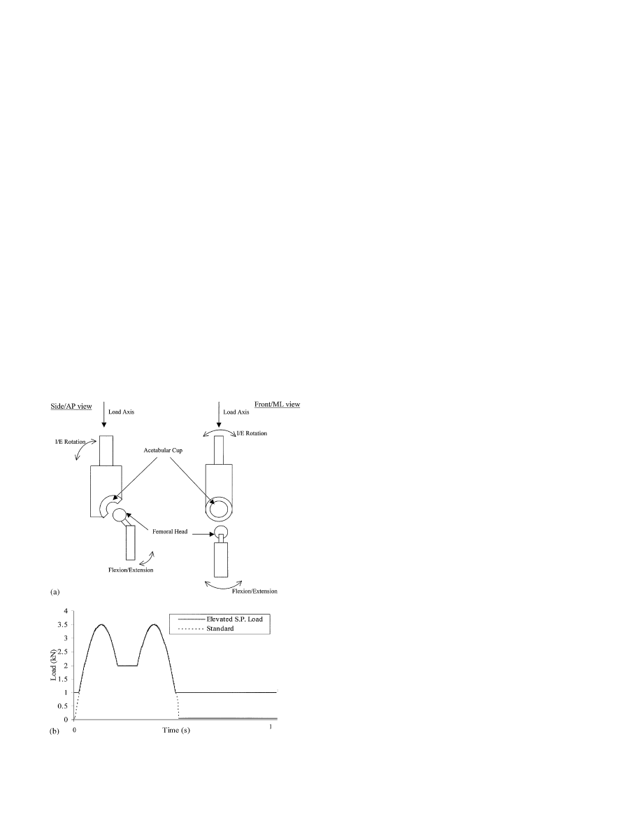
Fig. 1. Leeds PA2 hip joint simulator. (a) Diagram of the components
and axis. (b) Load cycle for standard and elevated swing phase load test.
This study was divided into two sections:
1. Five million cycle hip simulator study comparing the
relative wear resistance of HIPed and non-HIPed
alumina}alumina hip joints under standard testing
conditions.
2. Five million cycle simulator study comparing the rela-
tive wear resistance of HIPed and non-HIPed
alumina}alumina hip joints under various severe
tribological conditions.
2. Materials and methods
The hip simulator used (the Leeds PA2) was an in-
house designed, six-station machine in which the cup,
head and stem were positioned anatomically. This rig has
been previously described by Barbour et al. [3] and is
shown schematically in Fig. 1a. Using this simulator it
was possible to apply a single time-dependent vertical
load though the central axis of the cup (Fig. 1b); inter-
nal/external rotation
to
the
acetabular
cup
and
#exion/extension
to the femoral head. The loads and
motions were all independently controlled. All tests on
the alumina}alumina couples were run with the cups
positioned at 603 in the M/L plane [2] at a frequency of
1 Hz with the lubricant being replaced approximately
every 330,000 cycles. Flexion/extension motion of #30
and!153 was applied to the femoral component and an
internal/external rotation of $103 applied to the
acetabular cup, with the motions 903 out of phase.
This produced an open elliptical wear path. These
kinematic conditions have been shown to produce wear
rates and features similar to those found using three
independently controlled motions for UHMWPE acet-
abular cups were used [3]. A feature of this simulator
was that it tested the head and cup in an anatomical
position, with the face of the cup inclined to the axis of
the femur and the femoral head mounted at an anatom-
ical position on the femoral stem. The contact mechanics
and motions were similar to those found in vivo with the
contact area located on the superior quadrant of the
acetabular cup.
Wear was determined gravimetrically every million
cycles using an electronic balance with a resolution of
10
g and range of 250 g (Mettler). Density was used to
convert mass-to-wear volume, and wear rate mm
/mil-
lion cycles calculated. Average wear rates of the two
types of materials was compared by one-way analysis of
variance and the statistical signi"cance taken at the 95%
con"dence level. The surfaces were analysed using
a Rank Taylor Hobson 120L Talysurf contacting pro-
"lometer
at every measurement interval. A WYKO
NT2000 white-light interferometer was used to analyse
the surfaces at 2 and 5 million cycles of Test 1.
2.1. Part 1 * standard conditions testing
Three HIPed &BIOLOX forte' and three non-HIPed
&BIOLOX'
(manufacturer: CeramTec AG, Plochingen,
Germany) hip-bearing couples were supplied for this test.
All couples were of nominal 28 mm diameter in the ar-
ticulation geometry. The &BIOLOX forte' couples had an
average radial clearance of 32
m; the
&BIOLOX' couples
had an average radial clearance of 41
m. This di
!erence
in radial clearance was unintentional and not expected to
give signi"cantly di!erent results. The results from pre-
vious hip simulator studies [2,4] have shown that such
a small di!erence in radial clearance did not a!ect the
wear rate for similar materials. The cups were of a modu-
lar design and were held in purpose-made shells (manu-
facturer: Benoit Girard et cie, Herouville, France). All
heads were "xed onto &Orthinox' (manufacturer: Benoit
Girard et cie, Herouville, France) stems via a 12/14 taper.
The lubricant used was 25% (v/v) new-born calf serum
with 0.01% (w/v) aqueous sodium azide to act as an
antibacterial agent. The test was run to "ve million cycles
with measurements being taken every million cycles. The
loading cycle consisted of a simpli"ed twin peak wave-
form with peaks of 3.5 kN and a trough of 1 kN with
a pre-load of 50 N applied during the remaining 0.45 s of
2192
J.E. Nevelos et al. / Biomaterials 22 (2001) 2191}2197
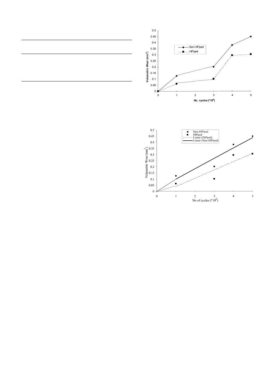
Table 1
Testing conditions
Condition Lubricant
Loading
No. of
stations
Test duration
(cycles)
1
Water
Standard
6
1
;10
2
Gelofusine
Standard
6
1
;10
3
25% serum
Elevated swing
phase load
6
3
;10
4
None
Standard
2
2.2
;10
Fig. 2. Cumulative volume loss for &BIOLOX' and &BIOLOX forte'
ceramic pairs.
Fig. 3. Data from hip simulator study 2 with linear regression.
the cycle [2,3]. The standard and elevated swing phase
load cycles are shown in Fig. 1.
2.2. Part 2 * severe tribological conditions
The same hip joints used for Part 1, i.e. three HIPed
&Biolox
forte' bearings and three non-HIPed &Biolox'
bearings were subsequently used for this study in order to
avoid any running-in e!ects. The testing conditions used
are shown in Table 1.
In test condition 1, Gelofusine
was selected as the
lubricant because it is a gelatin-based protein solution
free of lipids, which is used clinically. It was diluted to
25% (v/v) with 0.01% (v/v) aqueous sodium azide for this
test. This solution had fewer boundary lubricants than
serum and therefore its use may have increased wear.
In test condition 2, water with 0.01% (v/v) aqueous
sodium azide solution was used as a lubricant. The so-
dium azide was present as an antibacterial agent and
should not have a!ected the lubricating properties of
water. Water has no boundary lubricants and so in-
creased wear could have been produced when compared
to tests run in 25% (v/v) bovine serum.
In test condition 3, the swing phase load was raised to
1 kN in an attempt to deplete any lubricating "lm be-
tween the surfaces during this part of the load cycle.
A plot of the load cycle for this condition is shown in
Fig. 1b, 25% (v/v) bovine serum was again used as the
lubricant.
In test four, in which one bearing of each material was
run dry for a short period, the load cycle was returned to
the standard load cycle.
3. Results
3.1. Part 1 * standard testing conditions
The mean cumulative volume loss plotted against
number of loading cycles for all two material types is
presented in Fig. 2. The weight loss at two million cycles
was negative on all components and resulted in a large
weight gain (approximately equal to 0.1 mm
). The
measurement at this interval was repeated 3 times with
similar results. No adequate explanation for this could be
found (there was no signi"cant change in the weight of
a control cup which was left in the metrology laboratory),
although this may have been due to problems in the
cleaning of the components. This systematic error on all
components was not found at any other interval. It was
therefore decided to interpolate between the data points
at 1 and 3 million cycles for this data point. The weight
loss at 3 million cycles was calculated using the measured
weights at two million cycles.
The data for the cumulative weight losses but with
linear regression lines for the data at 1, 3, 4 and 5 million
cycles is presented in Fig. 3. A straight line was plotted
between the origin and the start of the linear regression
line in an attempt to show any &running-in' wear.
There did not appear to be a &running-in' stage
similar to that seen in other hip simulator studies
[2]. The two linear regression lines also appeared to be
diverging, which indicated that non-HIPed alumina
pairs had a slightly higher wear rate then HIPed alumina
pairs.
J.E. Nevelos et al. / Biomaterials 22 (2001) 2191}2197
2193
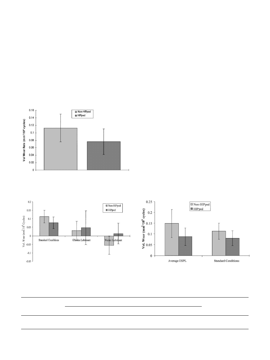
Table 2
Volumetric wear under elevated swing phase load conditions $95% con"dence limits
Material
Incremental volumetric wear (mm
)
Average volumetric wear
mm
/10 cycles
1
;10 Cycles
2
;10 Cycles
3
;10 Cycles
Non-HIPed
0.07$0.11
0.15$0.18
0.23$0.11
0.15$0.06
HIPed
0.04$0.08
0.11$0.05
0.11$0.17
0.09$0.04
Fig. 5. Relative wear rates of alumina ceramic bearings using di!erent
lubricants ($95% con"dence limits).
Fig. 4. Average wear rates of non-HIPed and HIPed alumina hip
bearings. ($95% con"dence limits).
Fig. 6. Average wear rates of alumina ceramic bearings under elevated
swing phase load conditions ($95% con"dence limits).
Average incremental wear rates were calculated using
volume losses at 1, 3, 4 and 5 million cycles and the
results are shown as a histogram in Fig. 4. The error bars
represent 95% con"dence limits.
The data showed lower wear for the HIPed alumina
components than for the non-HIPed components
(Fig. 4), although this di!erence was not statistically
signi"cant (p<0.05, Student's t-test).
No change in surface roughness was detected using
a Talysurf contacting pro"lometer. Very few wear fea-
tures were observed when the surfaces were analysed
using a WYKO NT2000 white-light interferometer at
either 2 or 5 million cycles.
3.2. Part 2 * severe tribological conditions
The wear rates in serum (standard conditions),
Gelofusine
and water are shown in Fig. 5. The data
from the standard conditions testing has been included
for comparison. From the data shown in Fig. 5 it can be
seen that the di!erent lubricants of gelofusine or water
did not increase the wear rates, but in fact produced wear
rates that were lower than the standard condition wear
rates. However, with such low values and the variability
in the data the di!erences were not statistically signi"-
cant p'0.05. The large error bars expressed as 95%
con"dence limits in the gelofusine
and water data were
due to the high variation in the data and small number of
samples (n"3) for each group. There was a weight gain
of the non-HIPed heads after testing in water. This
may have been due to a greater amount of metal transfer
to the internal taper surface. There was no change in
surface roughness of the articulating surfaces after either
test, as detected the Talysurf which has a resolution of
0.005
m R .
For test condition 3, the volumetric wear at each
million cycles as well as the overall average wear is shown
in Table 2. The average volumetric wear is shown as
a histogram in Fig. 6 along with standard conditions
data.
The wear rates using ESPL conditions were similar to
those found using more standard conditions as in Part 1.
After ESPL testing there was no increase in average
surface roughness although two incidences of surface
2194
J.E. Nevelos et al. / Biomaterials 22 (2001) 2191}2197
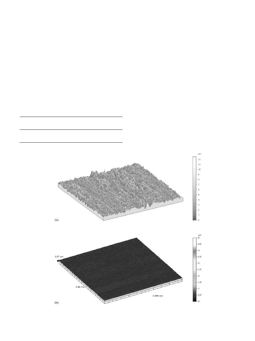
Fig. 7. (a) and (b) 3-D Talysurf traces within worn areas of non-HIPed head after dry testing (1 mm
;1 mm square area) [a] and after standard testing [b].
Table 3
Volumetric wear after 22,500 cycles of dry testing
Material
Head wear (mm
)
Cup
wear
(mm
)
Non-HIPed
30
10
HIPed
0
0
damage were observed after two million cycles:
1. There was a small &spot' of wear on one of the HIPed
alumina heads. This &spot' was approximately 2 mm in
diameter and was situated near the pole. As this dam-
age was not in the contact zone it was probable that
the damage was caused during the assembly of the
simulator.
2. Two parallel scratches were observed on one of the
non-HIPed heads. These scratches were in the contact
area and may have been caused by a third body.
Dry testing without any lubricant produced the most
severe wear condition and was carried out for only 22,500
cycles. Testing under this condition generated consider-
able noise. After 22,500 cycles it was noticed that the
non-HIPed cup holder was moving forward and back-
ward in the M/L direction by about 5 mm during each
cycle. The machine was stopped and very high wear was
immediately visible on both non-HIPed components.
The HIPed bearing had no visible wear at this stage.
Wear was determined gravimetrically as before and the
volume losses are shown in Table 3. This wear phenom-
enon was not repeatable.
Talysurf contacting pro"lometry of the severely worn
part of the non-HIPed femoral head showed a very rough
surface with a maximum R of 2.4
m and maximum
R values of 18m indicating a very severe wear mecha-
nism. Retrieved severely worn components have typical
R and R values of 0.2}0.4 and 2.5}3.5m, respectively
[1]. This severely worn surface is shown in Fig. 7a as
a three-dimensional talysurf trace taken within the wear
stripe, this data was "ltered using 0.25 mm cut-o!s. This
image can be compared with an undamaged surface
measured using a similar method after Test 1 shown in
Fig. 7b.
Following this measurement interval the non-HIPed
head and cup were rotated 1803 so that the contact area
J.E. Nevelos et al. / Biomaterials 22 (2001) 2191}2197
2195

was in an unworn area of both head and cup. The test
was then continued with the same conditions for a fur-
ther 77,500 cycles. No further macroscopic wear was
observed.
4. Discussion
The major aim of this study was to attempt to repro-
duce in vivo the wear rates and patterns found in retrieval
studies with non-HIPed alumina in order to evaluate any
improvement in wear properties due to HIPing.
Reported clinical wear rates (based on retrieval stud-
ies) for non-HIPed alumina}alumina prostheses vary
widely. Dorlot et al. [5] reported very low wear rates for
the majority of retrieved Ceraver-Osteal non-HIPed
alumina}alumina prostheses (0.0025
m/yr linear pen-
etration) with occasional cases of gross wear associated
with socket tilting and/or loosening. Mittelmeier et al.
[6] reported average wear rates of a few micrometres
penetration on each component per year from his series
(which corresponds to less than 1 mm
/yr). Nevelos et al.
[1] reported a retrieval study of Mittelmeier prostheses
in which the wear rates also varied from much less than
1 mm
per year to up to 260 mm per year for the most
severe cases. Such severe cases were extremely infrequent
and were associated with abnormal clinical histories such
as those including multiple dislocations and multiple
operations. Average wear rates for cases without extra
clinical complications were approximately 1 mm
/yr.
Therefore, the wear rates reported here from the simu-
lator under standard testing conditions were an order of
magnitude lower than the majority of reported clinical
wear rates for non-HIPed prostheses. Also none of the
wear patterns observed clinically, namely a &stripe' of
wear on the femoral head which was almost always
present and consisted of a roughened area with a typical
R of 0.1}0.2
m, were observed on the simulator speci-
mens after the lubricated testing.
Re"or et al. [7] reported wear rates of 0.4 mm
/10
cycles for non-HIPed alumina}alumina hip bearings
when tested in a Munchen-type hip simulator using
water as a lubricant. The wear rates for HIPed alumina
bearings under similar conditions were approximately
0.2 mm
/10 cycles. In the study reported here these
slightly elevated wear rates were not reproduced and
it appeared that changing the content of the lubricant
in this testing method had no signi"cant e!ect on the
wear rate.
Complete removal of the lubricant produced high fric-
tion and very severe wear of the non-HIPed material
with far more surface disruption than seen clinically,
however, the physiological basis for this test condition
was questionable.
The elevated swing phase load test was designed to
further deplete the lubricating "lm. However, the motion
remained a continuous walking cycle and so some lubri-
cant may have been entrained and protected the surfaces.
Therefore, it was not possible to reproduce clinically
relevant wear rates, patterns or mechanisms using the
testing protocols of this study. However, even under the
harsh but lubricated tribological conditions in this test,
the wear rates remained very low at approximately 400
times less than those observed for metal/UHMWPE
bearings. HIPed alumina demonstrated lower average
wear than non-HIPed alumina although this was not
statistically signi"cant (p'0.05, Students t-test). Further
changes to hip simulator protocols for ceramic}ceramic
bearings must be made in order to simulate clinically
relevant wear. Improvements in design and/or materials
of ceramic}ceramic THA cannot be validated until more
clinically relevant wear rates, patterns and mechanisms
are reproducible in vitro. In particular, new ceramic
material combinations such as zirconia}alumina [8] can-
not be validated without clinically relevant testing prior
to clinical use. More recently further studies [9] have
shown that microseparation of the head and cup during
swing phase and resulting rim contact at heel strike can
accelerate wear and replicate in vivo observed wear rates
and patterns.
5. Conclusions
1. Non-HIPed alumina had a higher wear rate than
HIPed alumina under standard physiological testing
conditions, although this di!erence was not statis-
tically signi"cant (p'0.05, Students t-test).
2. Changing the content of the lubricant did not
a!ect the wear rate of the alumina}alumina hip articu-
lation.
3. Application of an increased swing phase load did not
increase the wear rate of alumina}alumina hip articu-
lation.
4. Very high wear of the non-HIPed material was ob-
served when no lubricant was used although this was
not repeatable.
5. Clinically relevant wear rates, patterns and mecha-
nisms were not reproduced in this study and warrant
further study.
Acknowledgements
This work was funded by Stryker International and
Arthritis Research Campaign.
References
[1] Nevelos J, Ingham E, Doyle C, Fisher J, Nevelos AB. Examination
of alumina ceramic components from Mittelmeier total hip ar-
throplasties. J Biomater 1999;20:1833}40.
2196
J.E. Nevelos et al. / Biomaterials 22 (2001) 2191}2197

[2] Nevelos J, Ingham E, Doyle C, Nevelos A, Fisher J. In#uence
of
acetabular
cup
angle
on
the
wear
of
&Biolox
forte'
alumina/alumina hip joints in a physiological hip simulator. Trans-
actions of the 45th ORS, USA, 1999. p. 857.
[3] Barbour P, Stone M, Fisher J. A hip joint simulator study using
simpli"ed loading and motion cycles generating physiological wear
paths and rates. Proc Instn Mech Engrs 1999;213H:455}67.
[4] Oonishi H, Nishida M, Kawanabe K, Yamamoto K, Downs B,
Sorensen K, Good V, Braham A, Clarke I. In vitro wear of
Al2O3/Al2O3 implant combination with over 10 million cycles
duration. Transactions of the 45th ORS, USA, 1999. p. 50.
[5] Dorlot J-M, Christel P, Meunier A. Wear analysis of retrieved
alumina heads and sockets hip prostheses. J Biomed Mater Res:
Appl Biomater 1989;23:299}310.
[6] Mittelmeier H, Heisel J. Sixteen-years' experience with ceramic hip
prostheses. Clin Orthopaed 1992;282:64}72.
[7] Re"or HJ, Plitz W, Walter A. Ex vivo and in vitro analysis of the
alumina}alumina bearing system for hip joint prostheses. Proceed-
ings of the 10th International Symposium on Ceramics in Medi-
cine, 1997. p. 127}30.
[8] Villermaux F, Blaise L, Claes B, Drouin JM. Zirconia}alumina
total hip prosthesis:the logical evolution of alumina}alumina sys-
tem. Transactions of the 25th Society for Biomaterials, vol. 22,
1999. p. 135.
[9] Nevelos J, Ingham E, Doyle C, Streicher R, Nevelos A, Walters W,
Fisher J. Microseparation of alumina}alumina hip joints during
simulator testing produces clinically relevant wear rates. J Ar-
throplasty 2000;15:793}5.
J.E. Nevelos et al. / Biomaterials 22 (2001) 2191}2197
2197
Wyszukiwarka
Podobne podstrony:
wear of PEEK
37 509 524 Microstructure and Wear Resistance of HSS for Rolling Mill Rolls
17 209 221 Mechanical Study of Sheet Metal Forming Dies Wear
75 1067 1073 Elimination of Lubricants in Industries in Using Self Lubricating Wear Resistant
8 95 111 Investigation of Friction and Wear Mechanism of Hot Forging Steels
72 1031 1039 Influence of Thin Coatings Deposited by PECVD on Wear and Corrosion Resistance
Idiopathic chondrolysis of the hip
38 525 530 Wear Studies of Commercial and Ti Nb HSS
66 947 960 HIP Cladding of Tools
Periacetabular osteotomy for the treatment of dysplastic hip with Perthes like deformities
Effects of preoperative physiotherapy in hip osteoarthritis patients awaiting total hip replacement
MIS of the Hip and the Knee
Mechanical failure of external fixator during hip joint distraction for Perthes disease
87 1237 1248 Machinability and Tool Wear During the High Speed Milling of Some Hardened
COXARTHROSIS OF THE HIP AND THE KNEE
37 509 524 Microstructure and Wear Resistance of HSS for Rolling Mill Rolls
Hip hop in the age of empire Cape flat style Adam Haupt
więcej podobnych podstron