
INVESTIGATIONS OF FRICTION AND WEAR
MECHANISMS OF HOT FORGING TOOL STEELS
O. Barrau, C. Boher, C. Vergne and F. Rezai-Aria
Ecole des Mines d’Albi Carmaux
CROMeP - Route de Teillet
81013 Albi CT cedex 09
FRANCE
R. Gras
ISMCM-CESTI
3 rue Fernand Hainaut
93407 Saint-Ouen cedex
FRANCE
Abstract
Wear is one of the major life-limiting factor of the hot forging tools. A
complex interaction of friction-oxidation damages the surface of the tools by
the cyclic contact between the hot-worked piece and the tool. The aim of this
contribution is to assess some wear mechanisms of a martensitic tool steel at
various test temperature.
The tribological tests are performed on a high temperature pin-on-disc tri-
bometer designed in our laboratory. Experiments are carried out for different
disc temperatures ranging 20
◦
Cto 950
◦
C. The disc is heated up by a high
frequency induction heating.
Wear mechanisms are investigated by Scanning Electron Microscopy (SEM)
and Energy Dispersive Spectrometry (EDS). In addition, the state of the art
on tribology of oxides is undertaken. The oxides and their thickness play an
important part in friction and wear behaviour. In our study, the wear mecha-
nisms are essentially composed of abrasion, plastic deformation and fatigue.
Keywords:
Friction, wear, hot forging, martensitic steel, oxides, inelastic strain.
95
96
6TH INTERNATIONAL TOOLING CONFERENCE
INTRODUCTION
A significant part of the energy in forging is used to break the interfacial
junctions established by friction between the tool and the workpiece [1].
Moreover, the formation of an important oxide scale at the workpiece surface
leads to the consummation of a part of its substrate. In the same way, the
oxidation of the die and the delamination wear can considerably reduce the
tool life. At last, a too thick oxide scale on the die surface can influence the
flow of the hot material and can delay the cooling effect of the die on the
forged piece. All these observations can be translated in economical terms
and conclude to a bad contribution of the oxides in forging.
During the hot metal forming process, the forging tools are submitted to
thermal and mechanical cyclic stresses [25]. Under such working conditions,
tools are usually damaged through complex and interactive mechanisms
under cyclic loading like abrasive, adhesive and spalling wear, thermal and
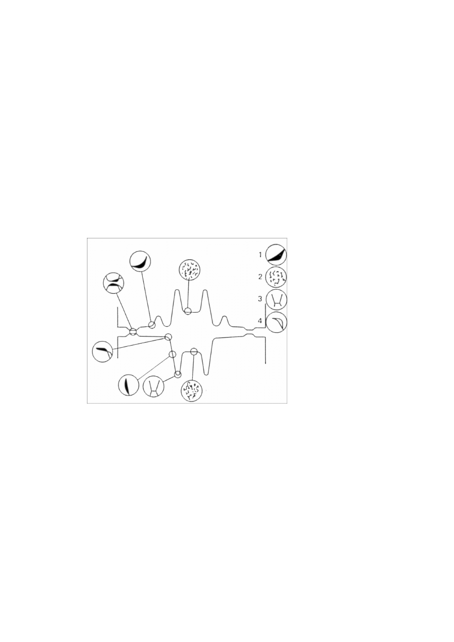
mechanical fatigue and plastic deformation [2, 3, 4] (Fig. 1).
Figure 1.
Common failure mechanisms for forging dies. 1. abrasive wear; 2. thermal
fatigue; 3. mechanical fatigue; 4. plastic deformation. [4].

Investigations of Friction and Wear Mechanisms of Hot Forging Tool Steels
97
In fact, for each fabrication operation, temperature variations occur more
or less quickly on the working tool surface due to the heat exchange between
the hot workpiece and the tool. Out of the contact, the die surface is quickly
cooled. Then, transient thermal gradients are developed inside the tool by
thermal conduction. These thermal gradients lead to crack the surface by
heat checking. Besides, tools undergo mechanical strains during forging
[5]. These strains can enhance diffusion ways in the die oxidation that plays
an important role in the tool wear. The damage caused by friction may be
very different according to the nature and the physical properties of formed
oxide layers. At last, under thermal and mechanical stresses, the martensitic
steel employed in hot forging tools are inclined to loose their mechanical
properties [6, 25, 26]. Also, the die surface damage is the result of a complex
process connected with fatigue (cracking origin), friction (wear origin) and
test ambience (oxidation origin). The aim of this contribution is to assess
some wear mechanisms of a martensitic tool steel at various test temperature.
The friction tests were performed on a high temperature pin-on-disc tri-
bometer developed in our laboratory, in order to control load, speed, tem-
perature, surface conditions and chemical state of the materials.
OXIDATION AND FRICTION
OXIDATION OF TRIBO-ELEMENTS
The tribological behaviour of a couple of two oxidized materials depends
on the thickness and the adherence of the oxide scales, and the type of contact.
To get better insight to the wear mechanisms between X38CrMoV5 steel and
AISI 1018 mild steel, the nature and the morphology of the oxides formed
on tribo-elements before friction test should be emphasized.
AISI 1018 mild steel is essentially composed of iron. Thus, the oxides
formed on the disc surface are principally iron oxides. The nature and the
structure of the oxides depend upon the temperature of oxidation and partial
oxygen pressure [10].
Below 560
◦
C [11], two oxide scales are formed. The top oxide is hematite
(Fe
2
O
3
) and the inner one is magnetite (Fe
3
O
4
). At the metal-oxide interface,
depending upon the Si content, a SiO
2
scale can be formed. For tempera-
tures inferior than 560
◦
C , the wustite (FeO) is unstable and transformed in
magnetite (Fe
3
O
4
).

98
6TH INTERNATIONAL TOOLING CONFERENCE
Above 570
◦
C , the three iron oxide appear and form a multi-layer oxide
composed from the substrate to the surface by FeO, Fe
3
O
4
and Fe
2
O
3
. At
the interface between the substrate and the wustite scale, the silicium oxide
(SiO
2
) can react with FeO to form a spinel composed, the fayalite (Fe
2
SiO
4
).
Between 570
◦
C and 700
◦
C , FeO scale increases with the temperature at
the expense of the other oxide scales. Above 700
◦
C and until 910
◦
C , the
oxide layer consists basically of a wustite scale [12]. But above 910
◦
C , FeO
scale decreases in aid of the hematite and magnetite scales which increase
again [13].
The oxidation of X38CrMoV5 steel is quite different from the AISI 1018
steel oxidation. The wustite (FeO) is not usually formed whatever the condi-
tions of oxidation [14]. It is reported [14, 15, 16, 17] that a chromium content
above 2 % leads to the disappearance of the wustite scale over 570
◦
C .
Then, the oxide scale formed on the X38CrMoV5 steel surface is duplex
[18]. The two layers are uniform and approximately equi-thickness. These
layers are very thin, about 100 µm after an oxidation of 150 hours at 650
◦
C .
The inner layer in contact with the parent metal results in internal oxidation
whereas the outer layer results in external oxidation. Also, the outer oxide
scale is formed by an iron-rich oxide and the inner scale is a mixed spinel
containing the alloying elements. The latter is made of an outer layer of
hematite (Fe
2
O
3
) and an inner layer of magnetite (Fe
3
O
4
) alloyed with spinel
of chromium (FeOCr) and vanadium (FeVO) [19].
WEAR BEHAVIOUR OF OXIDES
In general, the wear behaviour of iron oxides is complex [10, 20, 21, 22].
When a FeO scale is formed with a sufficient thickness, this scale takes in
charge the shear forces. At high temperature, an important oxide scale of
wustite tends to reduce friction coefficient and wear rate.
In the same way, the magnetite (Fe
3
O
4
) is known to play a lubricant role
and to tend to decrease the wear rate and the friction coefficient, whereas
the hematite (Fe
2
O
3
) is considered as an abrasive oxide which can enhance
considerably the high temperature wear and friction.
These behaviours are linked to the hardness level of iron oxides (Table 1).
The hematite(Fe
2
O
3
) presents the highest hardness and therefore is very
much prone to plastic shear accommodation. The stress flow of the wustite
(FeO) or the magnetite (Fe
3
O
4
) is lower than the substrate one. The plastic
deformation of oxide scales prevents the wear of the substrate. So these

Investigations of Friction and Wear Mechanisms of Hot Forging Tool Steels
99
oxide layers can be deformed before the bulk and they are considered as a
kind of solid lubricant.
Table 1.
Hardness of iron oxides measured at room temperature [10]
Oxide
FeO
Fe
3
O
4
Fe
2
O
3
Hardness (Hv)
270 – 300
420 – 500
1030
It seems important to precise that the plastic deformation of oxide scales is
usually due to diffusionnal-creep (Coble and Nabarro-Herring) mechanisms
and intergranular sliding [27, 28, 29, 30]. So, the plastic deformation of
oxides at temperature is quite different from the plastic deformation of metals
by dislocations movements.
The wear behaviour of the oxides also depends on both the thickness and
the adherence of oxide scales. It is established that the friction coefficient
decreases when the adherence of the oxides decreases and the thickness
increases [1, 23, 24].
Moreover, the thickness growth leads to an increase of the thermal resis-
tance. So, the thermal transfer at the friction interface can be reduced.
EXPERIMENTAL EQUIPMENT, PROCEDURE AND
MATERIALS
HIGH TEMPERATURE PIN-ON-DISC TRIBOMETER
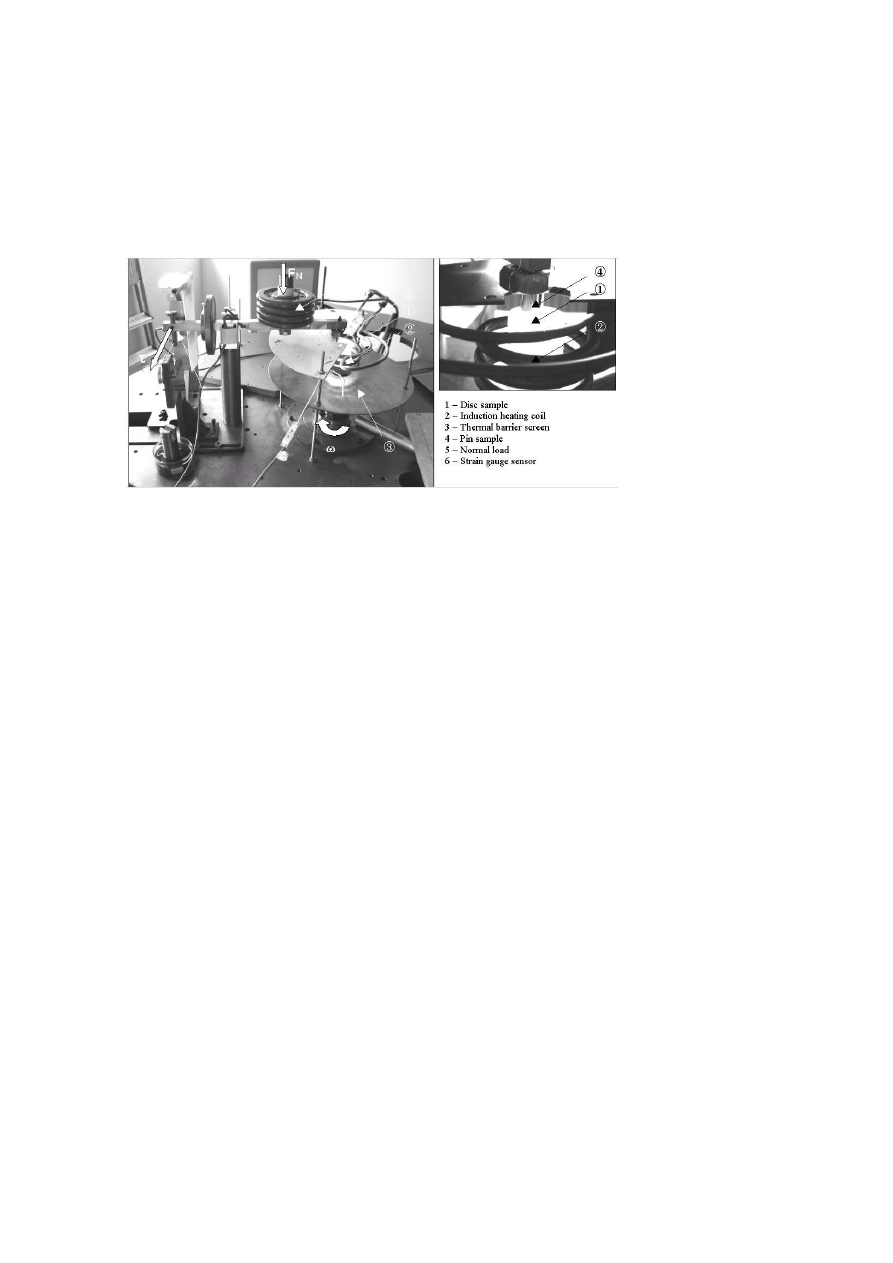
The high temperature tribometer developed in our laboratory was previ-
ously presented [7, 8].
The disc (Fig. 2 (1)) has a continuous rotating movement with an angular
speed ranging from 30 to 300 rpm. Depending upon radius of the wear track,
the linear velocity ranges from 0.05 to 50 ms
−1
. To reach the test temper-
ature, the disc can be heated up to 1100
◦
C by a high frequency induction
heating system (Fig. 2 (2)). The static disc surface temperature is measured
by a spot-welded K-thermocouples on a disc peripheral diameter. During
the rotation, the disc temperature is controlled by an IR-pyrometer placed
out of the contact area. A thermal screen protects the engine shaft from the
radiation of the disc at high temperature (Fig. 2 (3)).
100
6TH INTERNATIONAL TOOLING CONFERENCE
The pin presents a hemispherical contact surface with a radius of curvature
of 20 mm.
The loading is carried out using dead weight (maximum capacity 100 N
(Fig. 2 (5)). The tangential force is measured using a strain gauge sensor
placed parallel to the friction plane (Fig. 2 (6)). The friction coefficient is
recorded via a software developed on Labview in-house.
Figure 2.
High temperature pin-on-disc tribometer [8].
After every test, wear surfaces are observed by optical microscopy and/or
Scanning Electron Microscopy (SEM) with dispersive energy analysis ca-
pability.
TEST PROCEDURE
The disc is first heated up to a given constant temperature and kept at
temperature during one hour. During the disc heating, the pin is kept out of
the contact at room temperature. After one hour of heating of the disc, the
pin is put on the disc and the friction test is started immediately.
Thus, we consider that the initial contact between the pin and the disc is
in fact metal on oxide formed at high temperature.
To assess the effect of the disc temperature on wear damage, the normal
load (20 N) and the linear sliding speed (0.167 ms
−1
) are kept constant. Test
conditions are summarized in Table 2.

Investigations of Friction and Wear Mechanisms of Hot Forging Tool Steels
101
Table 2.
Friction test conditions
Pin initial
hardness
(HRC)
Normal load
(N)
Sliding
speed
Test
duration (s)
Disc
temperature
(
◦
C )
42
20
Rotate
100 rpm
Linear
0.167 ms
−1
3600
20
200
500
700
800
950
47
20
Rotate
100 rpm
Linear
0.167 ms
−1
3600
20
200
500
700
800
950
MATERIALS
The pin is made of a 5 % chromium martensitic steel grade (X38CrMoV5
steel, AISI H11 steel). Whereas the disc is a ferritic-pearlitic mild steel
(XC18, AISI 1018 steel). This X38CrMoV5 steel is widely used for forging
dies [4, 9], whereas AISI 1018 mild steel is used as a forged material in
automotive industry. The chemical composition of the both steels is reported
in Table 3.
The 5 % chromium steel was studied in quenched and tempered condi-
tions. The heat treatments were performed to achieve two initial hardness,
42 and 47 HRC with a tempered martensitic microstructure. The initial hard-
ness of AISI 1018 steel is about 168 HV at room temperature. The initial
arithmetic roughness of the disc and the pin are respectively 0.04 µm and
0.32 µm.

102
6TH INTERNATIONAL TOOLING CONFERENCE
Table 3.
Chemical composition of test materials
PIN
DISC
Elements (wt, %)
X38CrMoV5 / AISI H11 steel
AISI 1018 mild steel
C
0.40
0.16–0.22
Cr
5.05
< 0.40
Mn
0.49
0.40–0.70
V
0.47
—
Ni
0.20
< 0.40
Mo
1.25
< 0.10
Si
0.92
0.15–0.35
P
—
< 0.035
S
—
< 0.035
Fe
Bal.
Bal.
FRICTION AND SURFACE DAMAGE
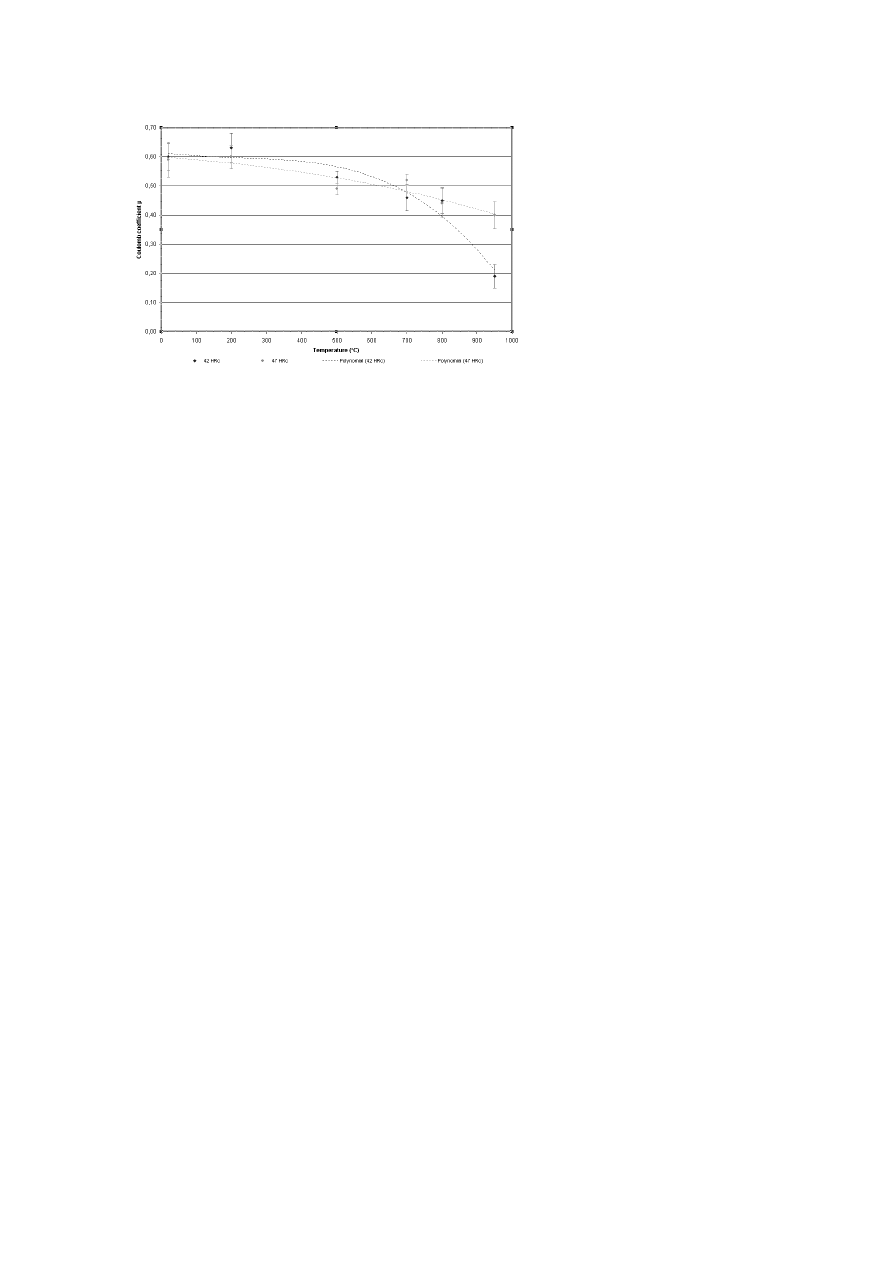
FRICTION EVOLUTION
Whatever the hardness of the pin (X38CrMoV5 steel), a decrease of the
average coefficient of friction is observed on the hole of tribological tests
when the temperature of disc increases. The average values of friction co-
efficient are in the range from 0.60 to 0.20 (Table 4 and Fig. 3).
Table 4.
Evolution of friction coefficient versus the disc temperature
Disc temperature (
◦
C)
20
200
500
42 HRC
0.60 ± 0.045
0.63 ± 0.050
0.53 ± 0.020
Average friction
coefficient 'µ
47 HRC
0.59 ± 0.060
0.60 ± 0.041
0.49 ± 0.020
Disc temperature (
◦
C)
700
800
950
42 HRC
0.46 ± 0.045
0.45 ± 0.044
0.19 ± 0.040
Average friction
coefficient 'µ
47 HRC
0.52 ± 0.020
0.44 ± 0.050
0.36 ± 0.049
At room temperature, the value of friction coefficient is characteristic of
a metal-metal contact. Between 500
◦
C and 800
◦
C , there is not a significant
Investigations of Friction and Wear Mechanisms of Hot Forging Tool Steels
103
Figure 3.
The evolution of friction coefficient versus the disc temperature.
evolution of friction coefficient. It stays around 0.50. But beyond 800
◦
C ,
the friction decreases drastically. Whatever the initial pin hardness, a break
in the linear friction evolution (between 20
◦
C and 700
◦
C ) versus tempering
is observed above 700
◦
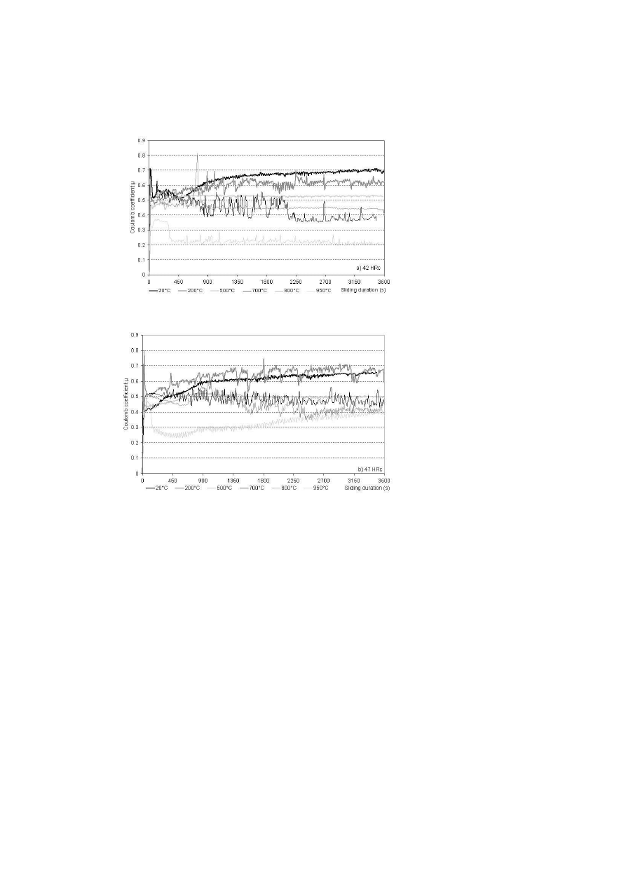
C . The evolution of friction observed on the friction
curves (Fig. 4) was represented for different pin hardness a) 42 HRC and b) 47
HRC. A non significant evolution of friction is observed versus the hardness
of the pin substrate. Below 700
◦
C , the friction coefficient decreases slightly
with hardness. At 500
◦
C , the friction coefficient stabilizes after 450 s around
an average value. With the temperature, the noise of the signal increases
until 800
◦
C to decrease again at 950
◦
C . But between 700
◦
C and 800
◦
C , the
friction does not achieve a stabilization and seems to decrease continuously.
At 950
◦
C , the friction stabilizes again after a running-in period of about
300 s, but with a more important noise than at 500
◦
C .
According to these friction curves, a high wear damage can be expected
between 500
◦
C and 950
◦
C .
Also, a critical point seems to exist between 700
◦
C and 800
◦
C from which
the friction behaviour of the couple X38CrMoV5 steel / AISI 1018 steel is
modified versus the disc temperature and the pin hardness.
104
6TH INTERNATIONAL TOOLING CONFERENCE
(a)
(b)
Figure 4.
Evolution of friction coefficient with a pin hardness of a) 42 HRC and b) 47
HRC.

Investigations of Friction and Wear Mechanisms of Hot Forging Tool Steels
105
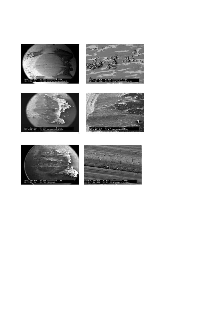
SURFACE DAMAGE
The surface damage are observed by SEM both on the disc and the pin
for each test temperature.
On the disc.
From room temperature to 500
◦
C , the oxide debris present
in the contact come from the abrasion of the surface asperities. They can
enter in the contact already as oxidized debris or they can be abraded as
metallic debris and be oxidized in the contact under shear force. Below
570
◦
C , FeO does not exist and the Fe
2
O
3
and Fe
3
O
4
oxides are very thin
layers especially at 20
◦
C .
These oxide debris are gradually agglomerated and compacted to form
partial compacted layers on the contact surface. Over 570
◦
C , the three ox-
ides are present on the disc surface and have a significant thickness. These
oxides now interfere in the contact between pin and disc and no more the
initial metallic substrate. With the temperature, these compacted oxide lay-
ers tend to become thicker and larger. So, the circulation of oxide debris
in the contact could come from the surface damage of compacted layers.
At low temperature, the debris are agglomerated but badly compacted com-
pared with the high temperature. The thermo-mechanical stresses favour
the decohesion of layers and a new and high generation of free debris in the
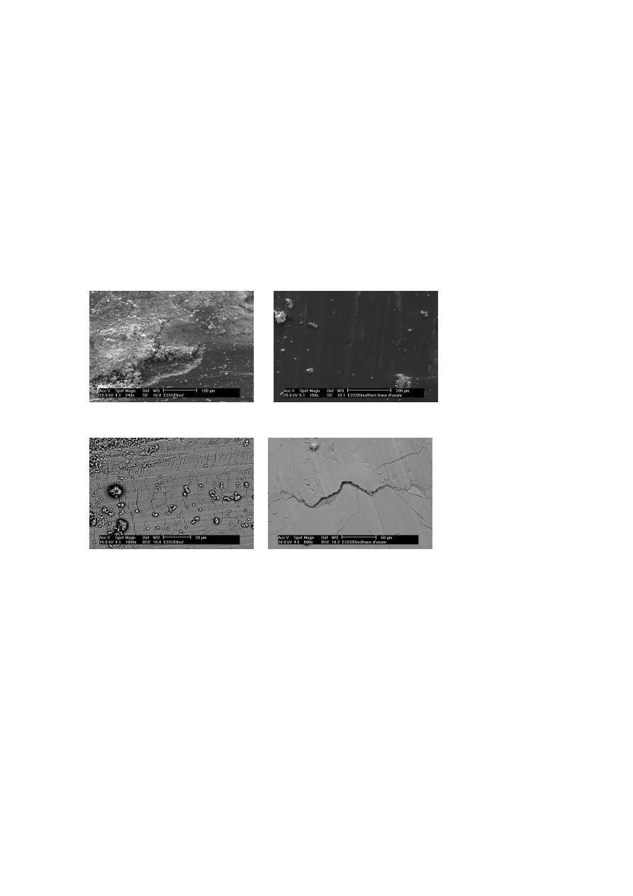
contact appears (Fig. 5 (a)). So, the friction coefficient remains quite high.
At 800
◦
C , the oxide debris form an important glazed surface in the wear
track of the disc (Fig. 5 (b)). So the formation of glazed surfaces in the
contact can be responsible of the softness of the friction coefficient at very
high temperature because they increase the carrying surface.
At high temperature, the cracks of glazed surfaces by fatigue could lead
to departures of matter of these layers by delamination and there is very
little free oxide debris in the contact (Fig. 5 (c) and (d)). At last, by the side
of the wear track, oxide debris are ejected from the contact and constitute
an agglomerated debris layer which increases with temperature. At high
temperature, these debris are compacted and contribute to extend the wear
track.
On the pin.
An edge of compacted oxide debris is formed in the front of
the wear track (Fig. 6 (a) and (c)). At 500
◦
C , we observe little debris edges
in the back of the wear track too (Fig. 6 (a)). The size of this edge increases
with the contact temperature.
106
6TH INTERNATIONAL TOOLING CONFERENCE
The pin wear track changes with the temperature. Below 500
◦
C , the pin
surface damage presents scares and compacted debris layers. The width and
the homogeneity of the layers increase with the temperature. At 500
◦
C , the
wear track is constitued by a layer which is composed of two zones (Fig. 6 (a)
and (b)). The dark zones contain a quantity of oxide more important than
the white zone. We suppose that the dark zones are iron oxides and the
white zones are close to the chemical composition of the metallic matrix.
These white areas could correspond to plastic deformation of asperities of
the matrix. These zones form a metal-oxide mixed zone (Fig. 6 (b)). At
700
◦
C , this mixed zone is gradually covered by a compacted layer of oxide
debris which tends to become glazed with higher temperature (Fig. 6 (c) and
(d)). At 800
◦
C , the mixed zone disappeared totally under the glazed surface
which presents cracks (Fig. 6 (e) and (f)).
(a) Generation of oxide debris from crack of
wear. Track at 700
◦
C.
(b) Formation of oxide glazed surface at 800
◦
C
(c) Crack of disc wear tracks at 700
◦
C.
(d) Crack of glazed surface leading to delamina-
tion at 800
◦
C.
Figure 5.
Wear damage on the disc.
Investigations of Friction and Wear Mechanisms of Hot Forging Tool Steels
107
(a) Compacted oxide edges at 500
◦
C.
(b) Compacted oxide edges at 500
◦
C.
(c) Compacted oxide edges at 700
◦
C.
(d) Mixed zone partially covered by the com-
pacted oxide layer at 700
◦
C.
(e) Wear track covered by oxide layer at 800
◦
C.
(f) Fracture of wear track at 800
◦
C.
Figure 6.
Wear damage on the pin.
108
6TH INTERNATIONAL TOOLING CONFERENCE
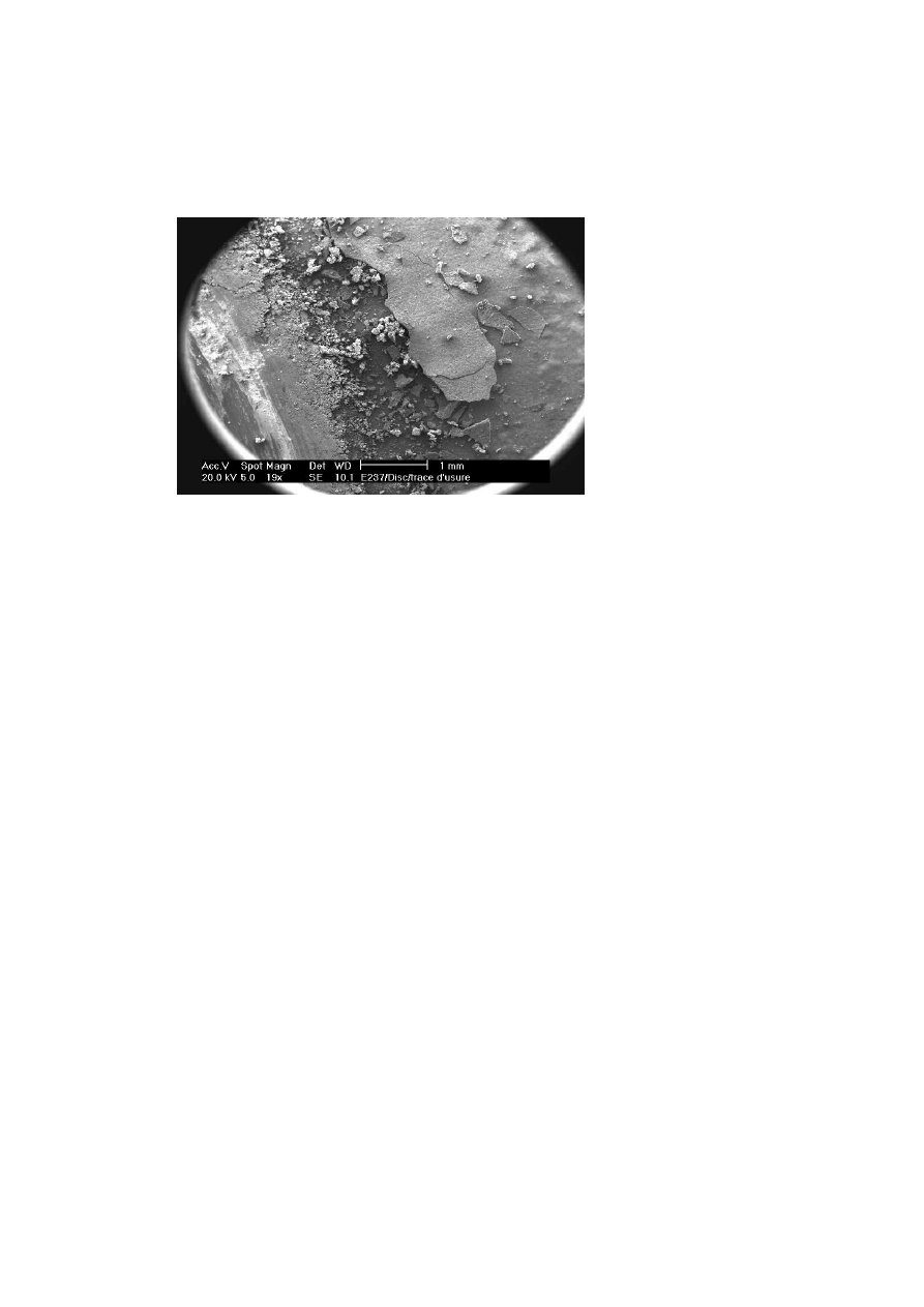
At 800
◦
C , we observe the crack of superficial oxide scale by the side of
the disc wear track (Fig. 7). So, we can suppose that the oxides present in
the contact, on the pin like on the disc, are hematite coming from the disc.
Figure 7.
Crack of the superficial oxide scale by the side of the disc wear track.
In addition, another damage mechanism feeding the wear in the couple
X38CrMoV5 steel on AISI 1018 steel is fatigue wear in the oxide layers.
The form of the cracks permit to find their physical origin (Fig. 8). The
form of the fatigue cracks is a horseshoe form. The form of thermal cracks
is close to the heat checking cracks. We could attribute fatigue cracks to
friction stress but the cooling of the disc after test could be responsible of
the thermal cracks.
DISCUSSION – CONCLUSION
With the increase of the test temperature, we observed a decrease of
friction coefficient. Whatever the hardness of the X38CrMoV5 pin substrate,
the evolution of friction is quite linear versus the temperature until 800
◦
C .
Over 800
◦
C , a different behaviour is observed depending on the hardness.
The 47 HRC pin stays linear while the 42 HRC pin becomes parabolic and
decreases drastically.

Investigations of Friction and Wear Mechanisms of Hot Forging Tool Steels
109
(a) Mechanical fracture.
(b) Thermal fracture.
Figure 8.
Origin of cracks of the oxide debris layers formed on wear tracks.
So, at high temperature, the flow stress of the 47 HRC steel stays superior
to the flow stress of the 42 HRC steel. With temperature and shear stress, pin
contact area presents plastic deformation. The plastic deformation of the 42
HRC pin may have a stronger influence on the friction and wear behaviour
of studied materials couple.
At each test temperature, the wear mechanisms identified on the disc like
on the pin are quite close. On the disc like on the pin, the oxides, observed
out of wear tracks like on the wear tracks, are essentially composed of iron
oxides. These iron oxides could essentially come from the disc oxide scale.
At the tribo-elements surfaces, more or less compact layers of oxide debris
are formed. The thickness and the density of these layers tend to increase
with the test temperature. Under thermo-mechanical stresses, these oxide
debris layers crack and generate free debris in the contact, responsible of
a high friction coefficient. The edges of compacted debris observed at the
back of the contact are the witness of a strong circulation of oxide debris in
the contact. With the increase of the temperature, the formation of glazed
surfaces is easier. The formation of these surfaces depends strongly on
the contact temperature, but not on the hardness of the pin substrate. These
glazed surfaces could decrease the contact pressure. So, at high temperature,
the formation of glazed surfaces and the capability of plastic flow of the pin
contact area under shear stresses could be responsible of the decrease of the
friction coefficient. In this case, the low friction coefficient observed is not
an admissible material property because it is due to the lost of pin mechanical
properties.

110
6TH INTERNATIONAL TOOLING CONFERENCE
In fact, wear mechanisms generated between X38CrMoV5 steel and AISI
1018 steel are essentially a combination of wear by abrasion, plastic defor-
mation of the matrix and superficial fatigue of both (oxide layers and matrix).
ACKNOWLEDGMENTS
The authors gratefully acknowledge PSA Peugeot-Citro'ën for support-
ing these investigations, in particular, Mr Marc PLATEAU. Dr. Sylvain
JEAN, from EMAC, is also thanked for his technical assistance in ESEM
observations (Environnemental Scanning Electron Microscopy).
REFERENCES
[1] L.H.S. LUNG, T. HEIJKOOP, Wear 71 (1981) p. 93–102.
[2] Y. THORE, PhD thesis Ecole des Mines de Paris (France) (1984).
[3] K. MAHJOUB, PhD thesis Ecole des Mines de Paris (France) (1999).
[4] ASM Handbook, Forming and Forging, ASM 14 (1988).
[5] D. KIRCHER, H. MICHAUD, V. BOGARD, Mat. & Tech. 1–2 (1999) p. 31–38.
[6] E DOEGE, H. N'ÄGELE, U. SCHLIEPHAKE, in Proceedings of the Institution of
Mechanical Engineers, Part B, Journal of Engineering Manufacture 208 (1994) p.
111-119.
[7] C.VERGNE, C. BOHER, R. GRAS,Wear 250 (2001) p. 322–333.
[8] C. VERGNE, PhD thesis Ecole des Mines de Paris (France) (2001).
[9] R. LEVEQUE, Techniques de l’Ing'énieur, M'étallurgie, M330 (1998) p. 1–42.
[10] P. BAQUE, P. FERNIER, Les Notes Techniques du CETIM 12 (1975).
[11] J. PADA'ÏSSI, Acta Metallurgica 3 (1955) p. 447–451.
[12] J. PADA'ÏSSI, Revue de M'étallurgie 54 N'°8 (1957) p. 569–585.
[13] N.B. PILLING, R.E. BEDWORTH, J. Inst. Met. 29 (1923) p. 529.
[14] E. GEMELLI, A. GALERIE, M. CAILLET, La Revue de M'étallurgie, CIT/Sciences
et des Mat'ériaux (1996) p. 261-267.
[15] F. ARMANET, PhD thesis Universit'é Technologique de Compi'ègnes (1984).
[16] V. R. HOWES, Corrosion Science 8 (1968) p. 729–736.
[17] V. R. HOWES, Corrosion Science 10 (1970) p. 99–103.
[18] A. OUDIN, PhD thesis Ecole des Mines de Paris (France) (2001).
[19] P. BRUCKEL, PhD thesis Ecole des Mines de Paris (France), work in progress.
[20] A. MAGNEE, C. GASPARD, D. COUTSOURADIS, Revue de M'étallurgie (1977)
p. 35–52.

Investigations of Friction and Wear Mechanisms of Hot Forging Tool Steels
111
[21] A. MAGNEE, C. GASPARD, J. MIGNON, L. HABRAKEN, Bulletin du Cercle
d’Etudes des M'étaux (1977) p. 177–241.
[22] A. MAGNEE, C. GASPARD, M. GABRIEL, Metallurgical Reports CRM 57 (1980)
p. 25–39.
[23] P. A. MUNTHER, J. G. LENARD, J. Mater. Process. Technol. 88 (1999) p. 105–113.
[24] D. T. BLAZEVIC, in processings of 37th MWSP Conf., ISS-AIME 33 (1996) p. 33-38.
[25] S.JEAN, B. MIQUEL, S. LEROUX, P. LAMESLE, F. R'ÉZA'Ï- ARIA, "Heat-checking
of hot work tool steels, " In Proceedings of SF2M of Temperature-Fatigue interaction,
May 2001, in press
[26] D. DELAGNES, F. REZAI-ARIA, C. LEVAILLANT, A. GRELLIER, in Proceedings
of the 5th International Conference on Tooling , Loeban (1999), p. 195-204.
[27] T. SUZUKI, S. TAKEUCHI, H. YOSHINAGA, Dislocation dynamics and plasticity
- Ed. Springer-Verlag (1991).
[28] F.R.N. NABARRO – Conference of Strength of Solids, Physical Society, London
(1948) p. 75.
[29] C. HERRING, J. Appl. Phys., Vol. 41, N'°437 (1950).
[30] R.L. COBLE, J. Appl. Phys., Vol. 34, N'°1679 (1963).
Wyszukiwarka
Podobne podstrony:
50 707 719 Thermal Fatique and Softening Behaviour of Hot Work Steels
96 1391 1402 Use of Hot Work Steels at PSA Peugeot Citroen
37 509 524 Microstructure and Wear Resistance of HSS for Rolling Mill Rolls
CONTROL AND THE MECHANICS OF START CHANGE AND STOP
3 T Proton MRS Investigation of Glutamate and Glutamine in Adolescents at High Genetic Risk for Schi
37 509 524 Microstructure and Wear Resistance of HSS for Rolling Mill Rolls
An investigation of shock induced temperature rise and melting of bismuth using high speed optical p
cathinone an investigation of several N alkyl and methylenedioxy substituted analogs pharmacolbioche
ABC Investigation of liver and biliary disease
Seahra The Classical and Quantum Mechanics of
Introduction to Lagrangian and Hamiltonian Mechanics BRIZARD, A J
a probalilistic investigation of c f slope stability
Endoscopic investigation of the Nieznany
więcej podobnych podstron