
15
. ELECTRICAL EQUIPMENT
15-0
ZX / SCOUT 50
15
__________________________________________________________________________________
__________________________________________________________________________________
__________________________________________________________________________________
__________________________________________________________________________________
__________________________________________________________________________________
ELECTRICAL EQUIPMENT
__________________________________________________________________________________
SERVICE INFORMATION........................................................ 15- 1
TROUBLESHOOTING.............................................................. 15- 1
CHARGING SYSTEM............................................................... 15- 3
BATTERY................................................................................ 15- 4
IGNITION SYSTEM ................................................................. 15- 7
STARTING SYSTEM................................................................ 15-11
15
15
. ELECTRICAL EQUIPMENT
15-1
ZX / SCOUT 50
SERVICE INFORMATION
GENERAL INSTRUCTIONS
• It is not necessary to check the battery electrolyte or fill with distilled water.
• Remove the battery from the motorcycle for charging. Do not remove the electrolyte cap..
• Do not quick charge the battery. Quick charging should only be done in an emergency..
• Charge the battery according to the charging current and time specified on the battery.
• When charging, check the voltage (open voltage) with an electric tester.
• When replacing the battery, do not use a traditional battery.
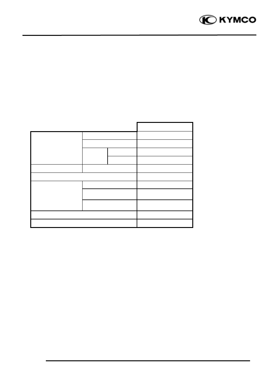
SPECIFICATIONS
SC10AS
Capacity
12V3AH
Voltage
13.0
13.2V
Charging
Standard
0.4A/10H
Battery
current
Quick
4A/0.5H
Spark plug
(NGK)
BR8HSA
Spark plug gap
0.6
0.7mm
Primary coil
0.153
0.187Ω
Secondary coil
(with plug cap)
6.99
10.21KΩ
Ignition coil resistance
Secondary coil
(without plug cap)
3.24
3.96KΩ
Pulser coil resistance (20
)
80
160Ω
Ignition timing
15.5°±2°BTDC/2000rpm
TROUBLESHOOTING
CHARGING SYSTEM
No power
Intermittent power
• Dead battery
• Loose battery cable connection
• Disconnected battery cable
• Loose charging system connection
• Fuse burned out
• Loose connection or short circuit in ignition system
• Faulty ignition switch
• Loose connection or short circuit in lighting system
Low power
Charging system failure
• Weak battery
• Loose, broken or shorted wire or connector
• Loose battery connection
• Faulty regulator/rectifier
• Charging system failure
• Faulty A.C. generator
• Faulty regulator/rectifier

15
. ELECTRICAL EQUIPMENT
15-2
ZX / SCOUT 50
IGNITION SYSTEM
No spark at plug
Engine starts but turns poorly
• Faulty spark plug
• Ignition primary circuit
• Poorly connected, broken or shorted wire
—Faulty ignition coil
—Between A.C. generator and CDI unit
—Poorly connected wire or connector
—Between CDI unit and ignition coil
• Ignition secondary circuit
—Between CDI unit and ignition switch
—Faulty ignition coil
—Between ignition coil and spark plug
—Faulty spark plug
• Faulty ignition switch
—Poorly insulated plug cap
• Faulty ignition coil
• Improper ignition timing
• Faulty CDI unit
—Battery voltage too low (6V max.)
• Faulty A.C. generator
—Faulty CDI unit
STARTING SYSTEM
Starter motor won‘t turn
Lack of power
• Fuse burned out
• Weak battery
• Weak battery
• Loose wire or connection
• Faulty ignition switch
• Foreign matter stuck in starter motor
• Faulty starter switch
or pinion
• Faulty front or rear stop switch
Starter motor rotates but engine does
• Faulty starter relay
not start
• Poorly connected, broken or shorted wire
• Faulty starter pinion
• Faulty starter motor
• Starter motor rotates reversely
• Faulty starter clutch
• Weak battery
15
. ELECTRICAL EQUIPMENT
15-3
ZX / SCOUT 50
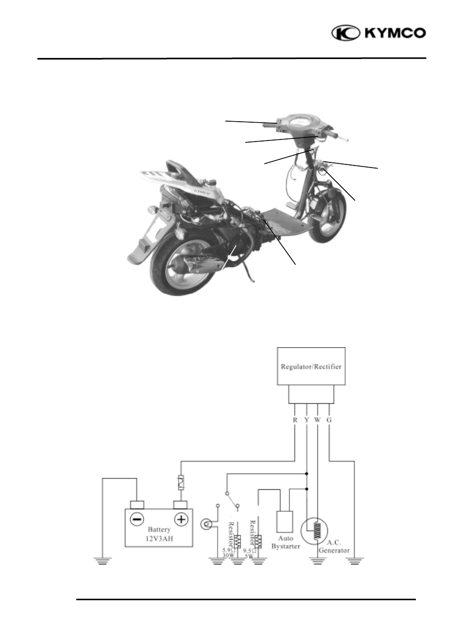
CHARGING SYSTEM
A.C. Generator
Dimmer Switch
Headlight Switch
Ignition Switch
Regulator/Rectifier
Resistor
Battery
7A
P
G/B
15
. ELECTRICAL EQUIPMENT
15-4
ZX / SCOUT 50
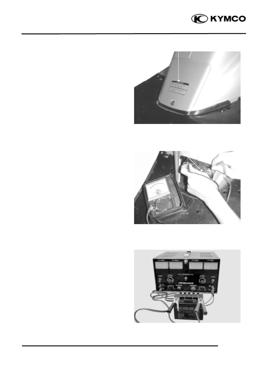
BATTERY
BATTERY REMOVAL
Remove the battery cover.
Disconnect the battery cables .
Remove the bolt and battery bracket.
Remove the battery.
The installation sequence is the reverse of
removal.
BATTERY CHARGING (OPEN CIRCUIT
VOLTAGE) INSPECTION
Remove the battery cover and disconnect
the battery cables.
Measure the voltage between the battery
terminals.
Fully charged : 13.0V
13.2V
Undercharged : 12.3V max.
CHARGING METHOD
Connect the charger positive (+) cable to
the battery positive (+) cable.
Connect the charger negative (-) cable to the
battery negative (-) cable.
Charging current : Standard : 0.4A
Quick
: 4A
Charging time
: Standard : 5 hours
Quick
: 0.5 hour
After charging: Open circuit voltage: 12.8V min.
Battery Cover
Power Lamp (Green)
Red
Black
Charging Lamp (Red)
Battery
15
. ELECTRICAL EQUIPMENT
15-5
ZX / SCOUT 50
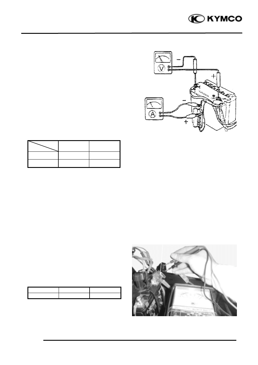
PERFORMANCE TEST
Warm up the engine.
Remove the floor mat and battery cover.
Stop the engine and open the fuse box.
Disconnect the wire lead from the fuse
terminal. Connect an ammeter between the
wire lead and fuse terminal as shown.
Connect the battery positive (+) terminal to
the voltmeter positive (+) probe and
battery negative (-) terminal to the
voltmeter negative (-) probe.
Start the engine, gradually increase engine
speed to test the output:
Position
RPM
Day
Night
2500
1.3A min.
1.0A min.
6000
2.0A min.
2.0A min.
Charging Limit Voltage: 14.5±0.5V/8000rpm
If the limit voltage is not within the
specified range, check the regulator/
rectifier.
A.C. GENERATOR (CHARGING
COIL) INSPECTION
Remove the met-in box. (12-4)
Disconnect the A.C. generator connector.
Measure the resistances between the
charging coil terminals (white–green) and
lighting coil terminals (yellow–green).
Resistances:
Charging coil white–green 0.2
1.2Ω
Lighting coil yellow–green 0.3
1.0Ω
Refer to 7-3 for A.C. generator removal.
A.C. Generator Connector
15
. ELECTRICAL EQUIPMENT
15-6
ZX / SCOUT 50
RESISTOR INSPECTION
Remove the frame front cover. (12-3)
Measure the resistance between the resistor
B pink wire and ground.
Measure the resistance between the resistor
A green/black wire and ground.
Resistances:
Resistor A: 9.9
10.5Ω
Resistor B: 5.6
6.2Ω
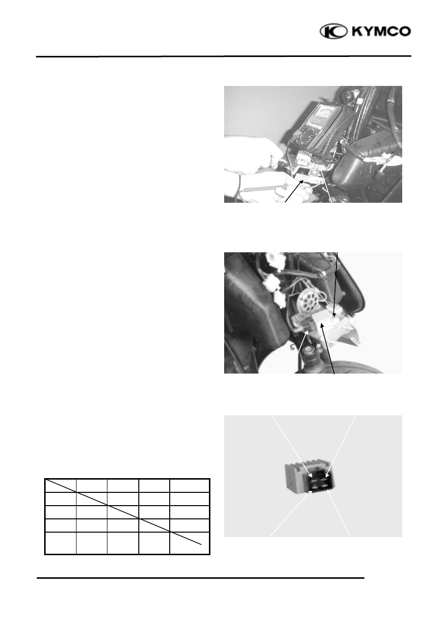
REGULATOR/RECTIFIER
INSPECTION
Remove the front cover. (12-3)
Disconnect the regulator/rectifier wire
coupler and remove the bolt to remove the
regulator/rectifier.
Measure the resistances between the
terminals.
Replace the regulator/rectifier if the readings
are not within the specifications in the table
below.
Probe⊕
Probe(-)
A (R) B (W)
C (Y)
D (G)
A (R)
B (W)
3-10KΩ
C (Y)
33-35KΩ
D (G)
33-
35KΩ
Coupler
A (Red)
C (Yellow)
D (Green)
B (White)
Resister A
Resister B
Regulator/Rectifier
Bolt
15
. ELECTRICAL EQUIPMENT
15-7
ZX / SCOUT 50
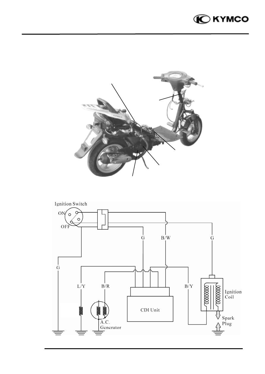
IGNITION SYSTEM
Ignition Coil
Pulser Coil
Ignition Switch
CDI Unit
A.C. Generator (Exciter Coil)
Pulser
Coil
15
. ELECTRICAL EQUIPMENT
15-8
ZX / SCOUT 50
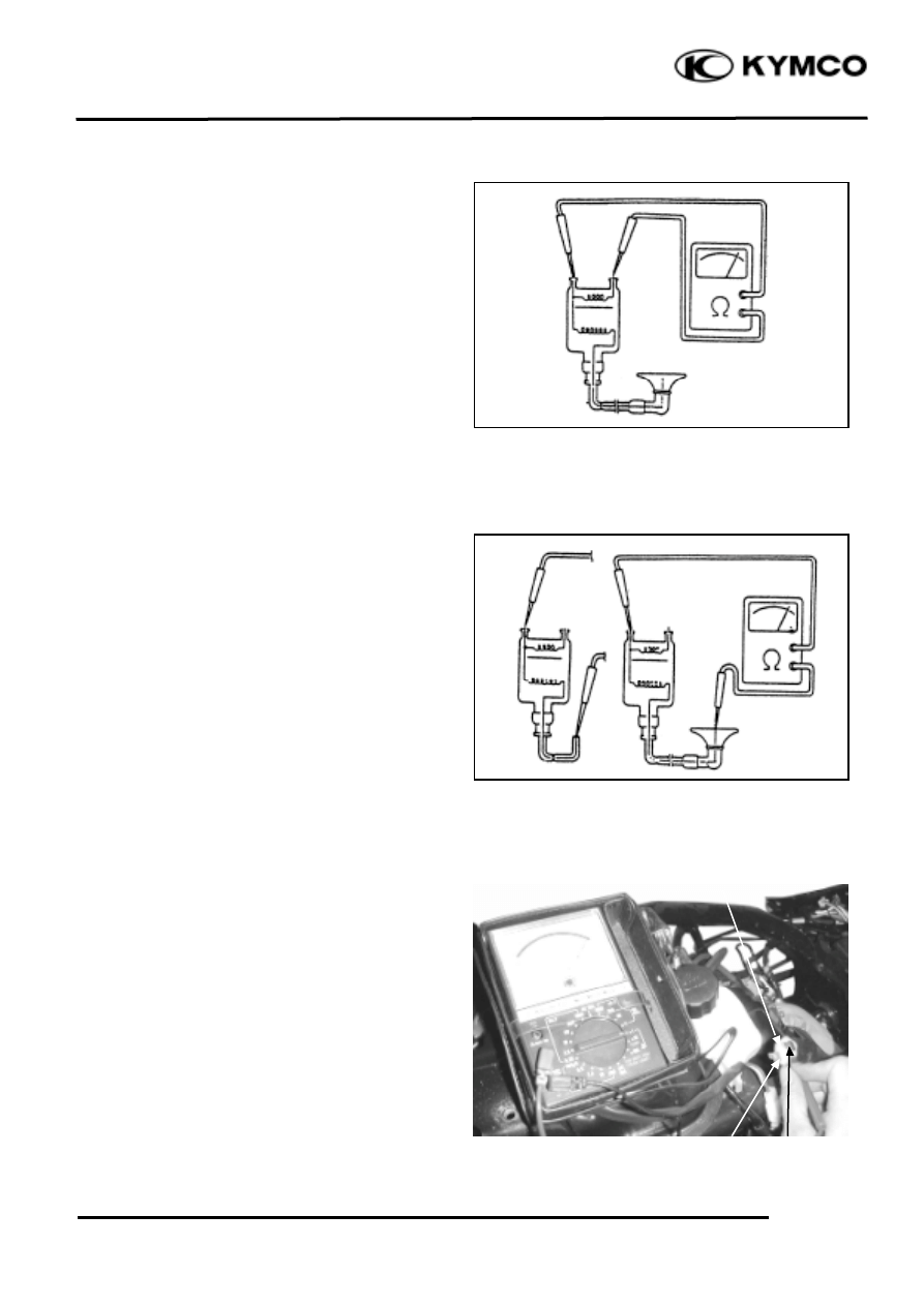
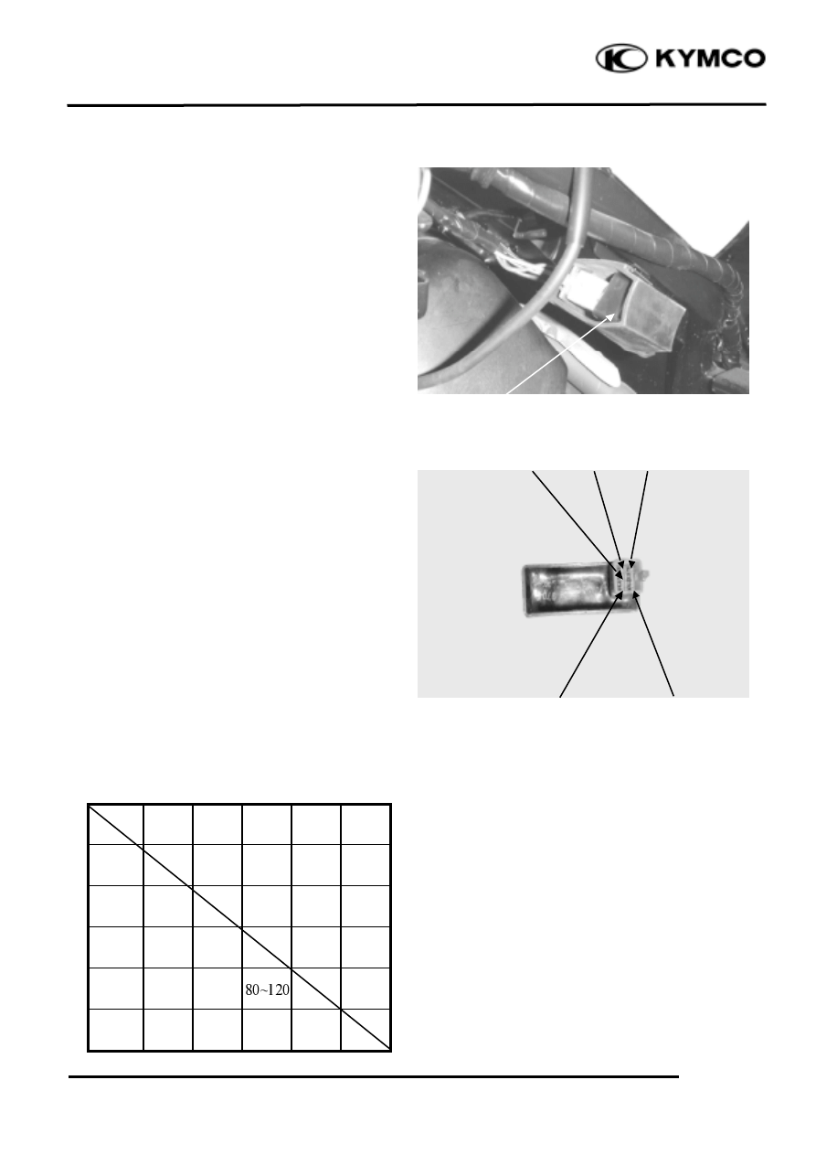
IGNITION COIL INSPECTION
Continuity Test
Remove the met-in box. (12-4)
Measure the resistance between the ignition
coil primary coil terminals.
Resistance (20
): 0.153
0.187Ω
Measure the secondary coil resistance
between the spark plug cap and the primary
coil terminal as Figure A shown.
Resistance (20
) (with plug cap):
6.99
10.21KΩ
Measure the secondary coil resistance
between the ignition coil terminal and the
primary coil terminal as Figure B shown.
Resistance (20
) (without plug cap):
3.24
3.96KΩ
Ignition Coil
Green
Figure A
Figure B
Black
15
. ELECTRICAL EQUIPMENT
15-9
ZX / SCOUT 50
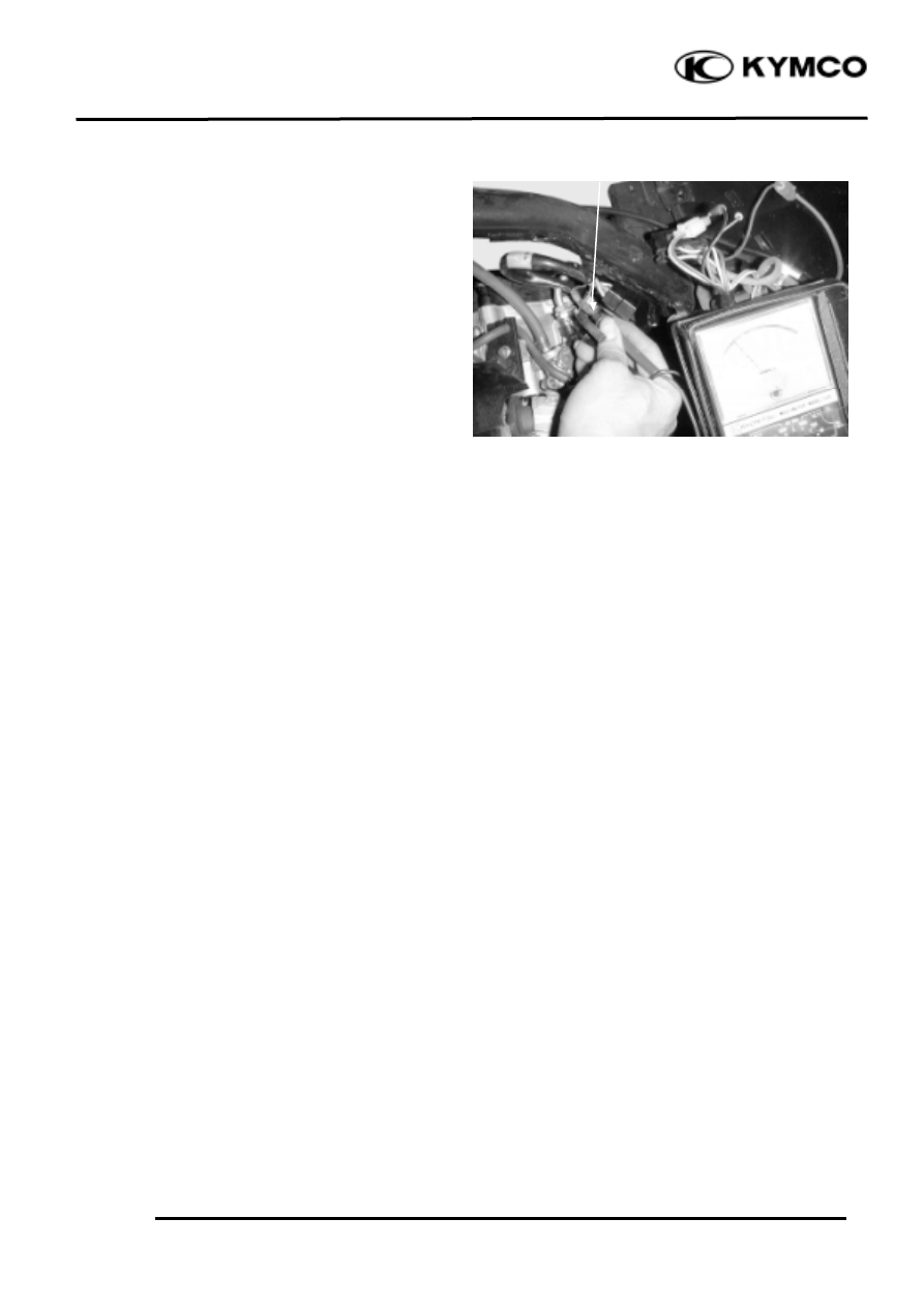
A.C. GENERATOR
Exciter Coil/Pulser Coil Inspection
Remove the met-in box. (12-4)
Disconnect the A.C. generator wire
connector.
Measure the pulser coil resistance between
the blue/yellow wire and ground.
Resistance (20
): 80
160Ω
Blue/Yellow
15
. ELECTRICAL EQUIPMENT
15-10
ZX / SCOUT 50
CDI UNIT INSPECTION
Remove the battery cover.
Disconnect the CDI coupler and remove the
CDI unit.
CDI CIRCUIT INSPECTION
Measure the resistance between the
terminals.
Replace the CDI unit if the readings are not
within the specifications in the table below.
Use the
x
KΩ range for the Sanwa Tester.
Use the
x
100Ω range for the Kowa Tester.
Unit: KΩ
Probe
⊕
(-)
Probe
Black/
Yellow
Black/
Red
Black/
White
Blue/
Yellow
Green
Black/
Yellow
Black/
Red
1~10
Black/
White
Blue/
Yellow
3~40
10~30
Green
2~10
10~30
CDI Unit
Green
Blue/Yellow
Black/
White
Coupler
Black/
Yellow
Black/
Red
15
. ELECTRICAL EQUIPMENT
15-11
ZX / SCOUT 50
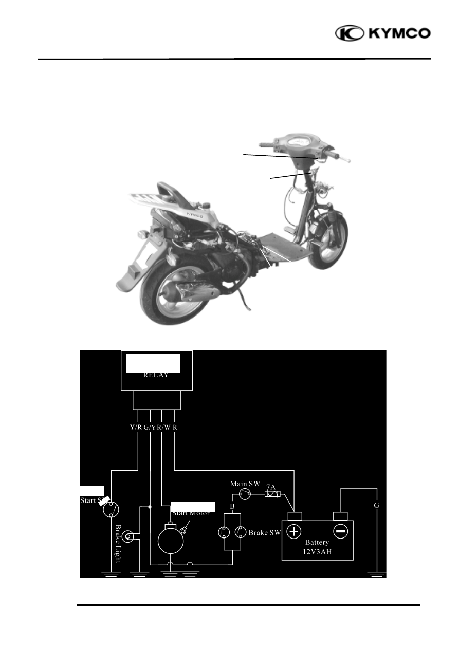
Starting System
Starter Button
Ignition Switch
Starter Relay
Battery
Starter Button
Starter Button
Starter Morter
Starter
Relay
15
. ELECTRICAL EQUIPMENT
15-12
ZX / SCOUT 50
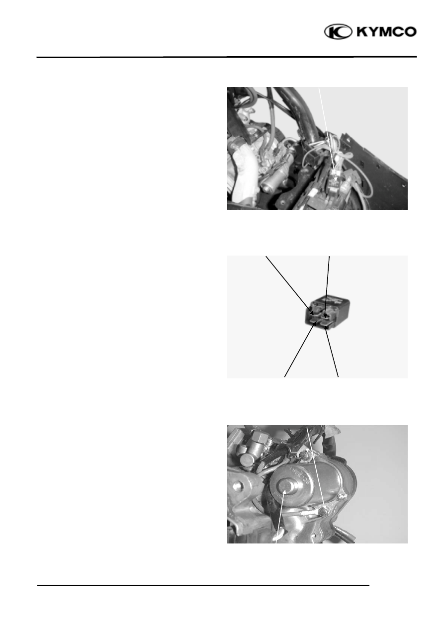
STARTER RELAY INSPECTION
Remove the battery cover.
Disconnect the starter relay coupler and
then remove the starter relay.
Connect the starter relay green/yellow
terminal to the 12V battery positive (+)
terminal and the relay yellow/red terminal
to the battery negative (-) terminal. Check
for continuity between the starter relay red
and red/white terminals. The relay is
normal if there is continuity.
STARTER MOTOR REMOVAL
Disconnect the starter motor cable.
Remove the two bolts attaching the starter
motor and remove the starter motor.
The installation sequence is the reverse of
removal.
AC 110V
Starter Relay
Green/Yellow
Starter Motor
Red/White
Bolts
Yellow/Red
Red
15
. ELECTRICAL EQUIPMENT
15-13
ZX / SCOUT 50
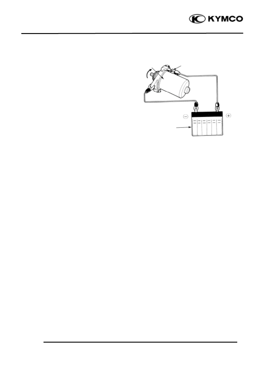
STARTER MOTOR INSPECTION
Connect a battery across the starter motor
and check for its operation.
Battery
Starter Motor
Battery (+) Terminal
Wyszukiwarka
Podobne podstrony:
ZX50 cap 17 (imp scarico)
ZX50 cap 12 (plastiche)
ZX50 cap 09 (riduzione finale)
ZX50 cap 08 (trasmissione)
ZX50 cap 00 (prefazione)
ZX50 cap 04 (lubrificazione)
ZX50 cap 11 (carburatore)
ZX50 cap 07 (statore volano)
ZX50 cap 14 (ruota freno sospensione post)
ZX50 cap 01 (indice e specifiche)
epilepsy cap 15
ZX50 cap 16 (strumentazione interruttori luci)
ZX50 cap 13 (manubrio ruota freno sospens ant)
ZX50 cap 02 (info generali)
ZX50 cap 06 (testa cilindro pistone)
ZX50 cap 05 (rimozione motore)
ZX50 cap 03 (manutenzione)
więcej podobnych podstron