
16
. INSTRUMENT/SWITCHES/LIGHTS
16-0
ZX / SCOUT 50
16
__________________________________________________________________________________
__________________________________________________________________________________
__________________________________________________________________________________
__________________________________________________________________________________
__________________________________________________________________________________
INSTRUMENT/SWITCHES/LIGHTS
__________________________________________________________________________________
SERVICE INFORMATION........................................................ 16-1
TROUBLESHOOTING.............................................................. 16-1
FUEL UNIT.............................................................................. 16-2
OIL METER ............................................................................. 16-3
SWITCHES .............................................................................. 16-5
STOP SWITCH INSPECTION/HORN ........................................ 16-6
BULB REPLACEMENT ............................................................ 16-7
INSTRUMENT/HEADLIGHT.................................................... 16-8
16

16
. INSTRUMENT/SWITCHES/LIGHTS
16-1
ZX / SCOUT 50
SERVICE INFORMATION
GENERAL INSTRUCTIONS
• Wires should be connected to other wires of the same color. Couplers must be connected to other
couplers of the same color.
• All plastic plugs have locking tabs that must be released before disconnecting, and must be aligned
when reconnecting.
• After installation of each switch, a continuity check must be performed.
TROUBLESHOOTING
Lights do not come on when ignition
Motor oil indicator light does not come on
switch is “ON”
(when motor oil is insufficient)
• Burned bulb
• Fuse burned out
• Faulty switch
• Dead battery
• Broken or shorted wire
• Faulty ignition switch
• Fuse burned out
• Faulty instrument
• Weak battery
• Faulty oil meter
• Poorly connected wire
• Faulty winker
Motor oil indicator light winks
• Loose wire connection
Light dims
• Broken wire
• Faulty ignition coil
• Faulty oil meter
• Wire or switch resistance too high
• Faulty regulator/rectifier
Fuel gauge pointer does not register
correctly
Headlight does not change when dimmer
• Disconnected wire or connector
switch is turn to Hi or Lo
• Broken wire
• Faulty or burned bulb
• Faulty float
• Faulty dimmer switch
• Faulty fuel unit
• Faulty instrument
Fuel gauge pointer fluctuates or swings
• Loose wire connection
• Faulty fuel unit
• Faulty instrument
16
. INSTRUMENT/SWITCHES/LIGHTS
16-2
ZX / SCOUT 50
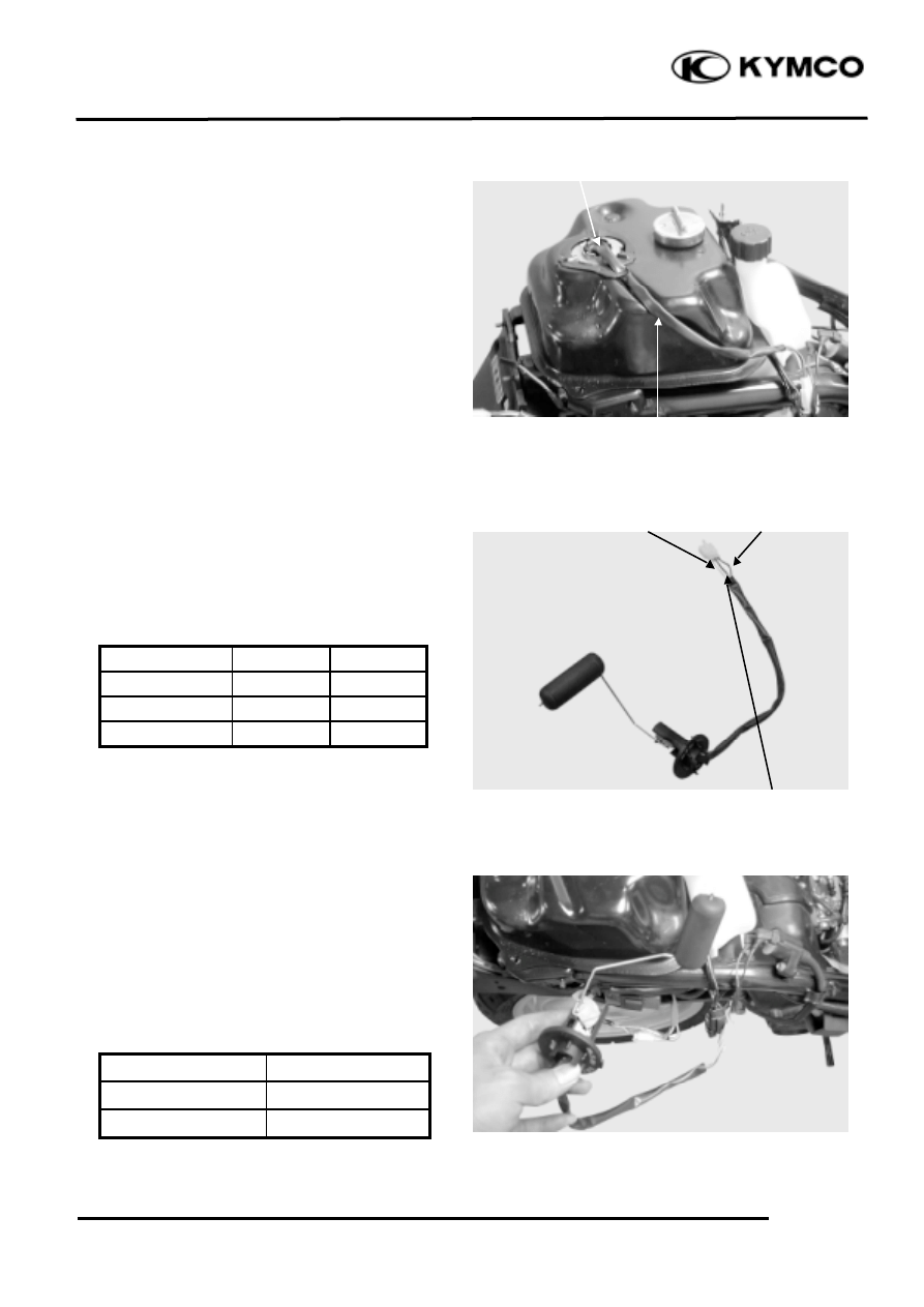
FUEL UNIT
REMOVAL
Remove the frame body cover. (12-5)
Disconnect the fuel unit wire connectors.
Turn the fuel unit retainer counterclockwise
to remove it.
Remove the fuel unit.
INSPECTION
Remove the fuel unit.
Measure the resistance between the fuel
unit wire terminals with the float at upper
and lower positions.
Wire Terminals
Upper
Lower
G
Y/W
33Ω
686Ω
G
L/W
566Ω
53Ω
Y/W
L/W
600Ω
600Ω
FUEL GAUGE INSPECTION
Connect the fuel unit wire connectors and
turn the ignition switch “ON”.
Check the fuel gauge needle for correct
indication by moving the fuel unit float up
and down.
Float Position
Needle Position
Upper
“F” (Full)
Lower
“E” (Empty)
Y/W
AC 110V
Fuel Unit Wire
Fuel Unit
G
L/W
16
. INSTRUMENT/SWITCHES/LIGHTS
16-3
ZX / SCOUT 50
INSTALLATION
The installation sequence is the reverse of
removal.
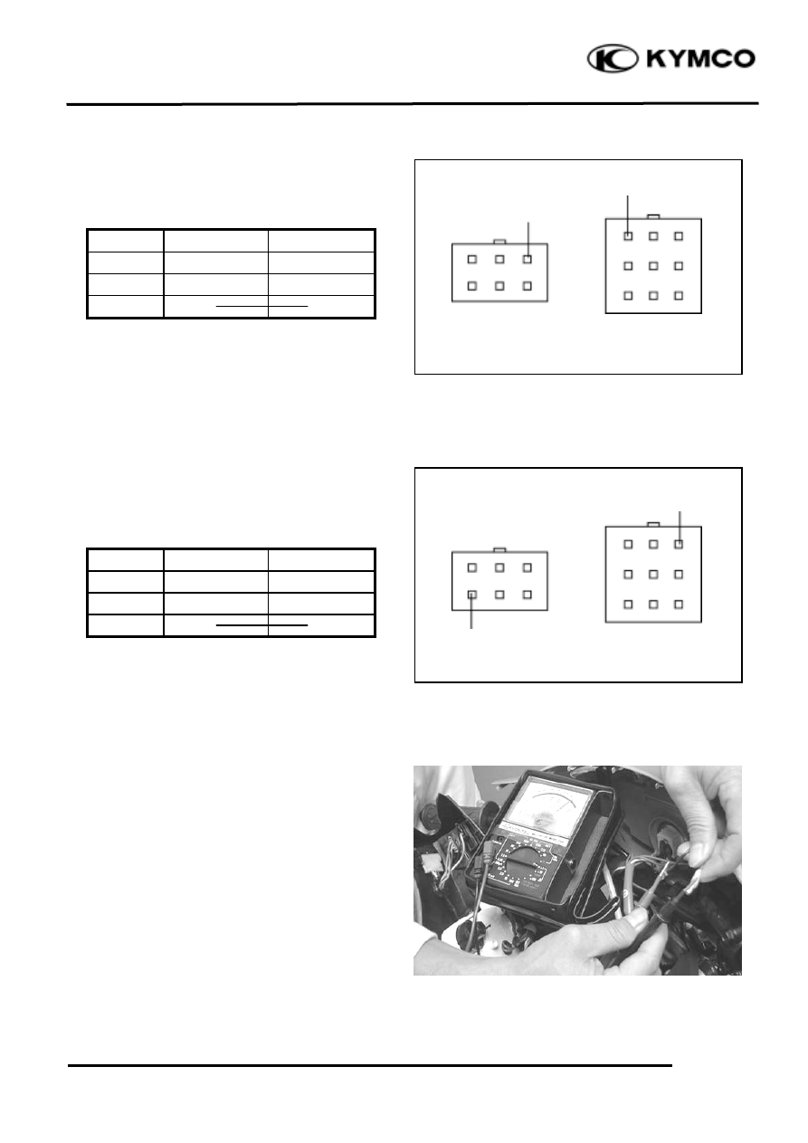
OIL METER
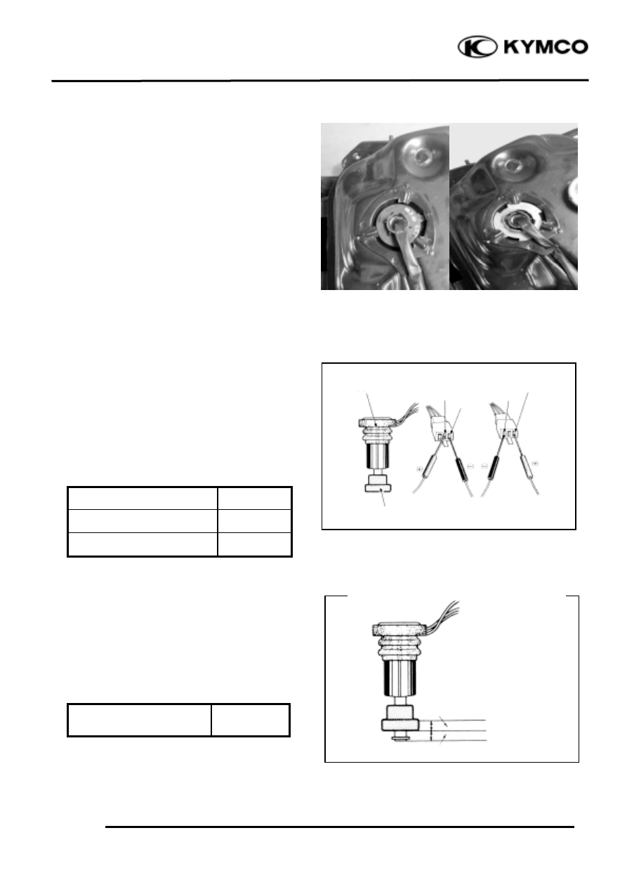
INSPECTION
Remove the met-in box. (12-4)
Remove the frame body cover. (12-4)
Disconnect the oil meter wire connectors
and remove the oil meter. Keep the oil
meter float at the lower position.
Measure the resistances between the wire
terminals as and shown in the left
figure.
Wire Terminals
Resistance
Green/Red(+)
Black(-)
5
16Ω
Green(-)
Black(+)
Oil Meter Operation Inspection
Connect the oil meter wire connectors and
turn the ignition switch ON.
Measure the resistance between the wire
terminals with the float at upper position.
Green/Red(+)
Black(-) About 340Ω
Light OFF
Light ON
Retainer
G
G
Float
G/R
B
B
Oil Meter
4.5
1.0m
m
16
. INSTRUMENT/SWITCHES/LIGHTS
16-4
ZX / SCOUT 50
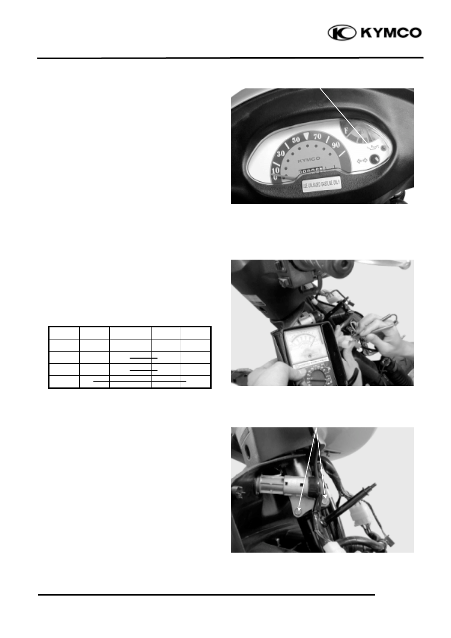
Move the oil meter float up and down to
see if the oil indicator light will go out and
come on.
SWITCHES
IGNITION SWITCH INSPECTION
Remove the front cover. (12-3)
Disconnect the ignition switch wire
couplers and check for continuity between
the wire terminals.
Color
Red
Black/White Green Black
Symbol BAT
1
IG
E
BAT
2
LOCK
OFF
ON
IGNITION SWITCH REPLACEMENT
Remove the front cover. (12-3)
Disconnect the ignition switch wire
couplers.
Remove the two mounting bolts and remove
the ignition switch.
The installation sequence is the reverse of
removal.
Oil Indicator Light
Ignition Switch Coupler
Bolts
16
. INSTRUMENT/SWITCHES/LIGHTS
16-5
ZX / SCOUT 50
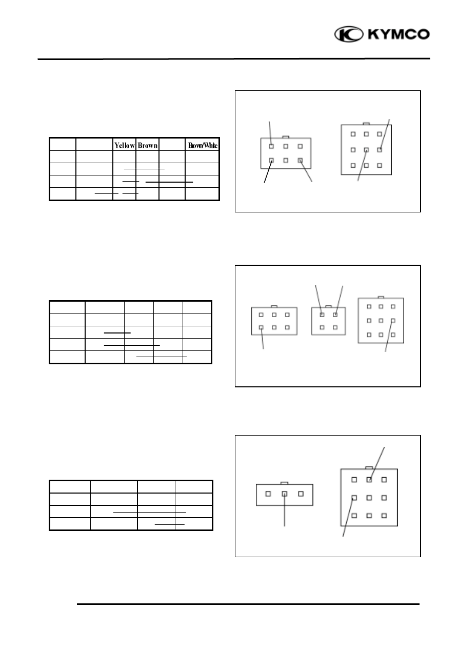
HEADLIGHT SWITCH INSPECTION
Remove the handlebar rear cover. (12-3)
Disconnect the headlight switch wire
coupler and check for continuity between
wire terminals.
Color Blue/White
Pink
Symbol
HL
CL
TL
RE
OFF
P
H
DIMMER SWITCH INSPECTION
Check for continuity between wire
terminals.
Color Blue/White Blue White Black
Symbol
HL
HI
LO
PASS
HI
LO
PASSING
TURN SIGNAL SWITCH
INSPECTION
Check for continuity between the wire
terminals.
Color
Light Blue
Orange
Gray
Symbol
R
L
WR
R
L
Headlight Switch
AC 110V
Dimmer Switch
SB
Turn Signal Switch
O
Gr
L
W
B
L/W
Y
Br/W
P
L/W
Br
16
. INSTRUMENT/SWITCHES/LIGHTS
16-6
ZX / SCOUT 50
STARTER SWITCH INSPECTION
Check for continuity between wire
terminals.
Push the starter button when measuring.
Color
Yellow/Red
Green
Symbol
ST
E
FREE
PUSH
HORN SWITCH INSPECTION
Check for continuity between wire
terminals.
Push the horn button when measuring.
Color
Light Green
Black
Symbol
HO
BAT
2
FREE
PUSH
STOP SWITCH INSPECTION
Remove the handlebar front cover. (12-3)
Disconnect the front and rear stop switch
wire couplers.
Check for continuity between the wire
terminals when the front/rear brake lever is
applied.
Horn Switch
B
Lg
Starter Switch
Y/R
G
16
. INSTRUMENT/SWITCHES/LIGHTS
16-7
ZX / SCOUT 50
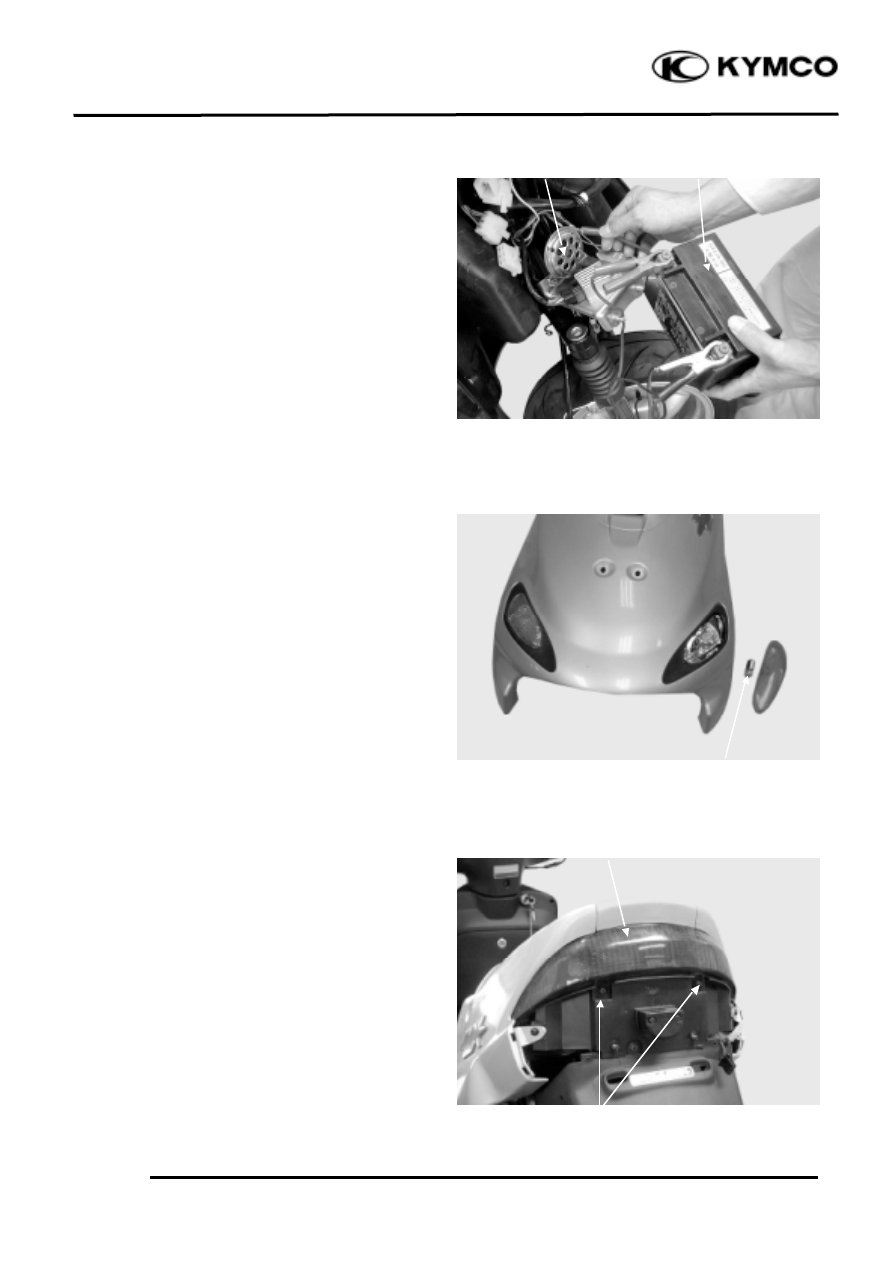
HORN INSPECTION
Remove the frame front cover. (12-3)
Disconnect the horn wire couplers. The
horn is normal if it sounds when a 12V
battery is connected across the horn wire
terminals.
FRONT TURN SIGNAL LIGHT
REPLACEMENT
Remove the turn signal light shell and the
bulb.
Replace with new ones.
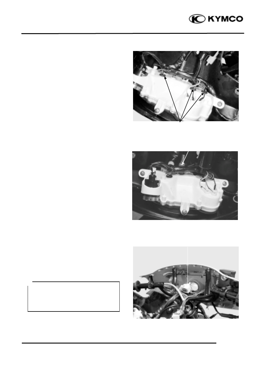
TAILLIGHT/STOPLIGHT/REAR TURN
SIGNAL LIGHT BULB REPLACEMENT
Taillight Shell Removal:
Remove two screws attaching the taillight
shell.
Remove the taillight shell and stop light
bulb.
Remove the rear turn signal light bulbs.
The installation sequence is the reverse of
removal.
Taillight Shell
AC 110V
Turn Signal Light Bulb
Horn
Battery
Screws
16
. INSTRUMENT/SWITCHES/LIGHTS
16-8
ZX / SCOUT 50
INSTRUMENT
Instrument Bulbs Replacement
Remove the handlebar rear cover. (12-3)
Remove the bulbs and replace with new
ones.
SPEEDOMETER REMOVAL
Disconnect the speedometer cable.
Disconnect the speedometer wire
connector.
Remove the three screws attaching the
speedometer.
Remove the speedometer.
The installation sequence is the reverse of
removal.
HEADLIGHT
REMOVAL/BULB REPLACEMENT
Remove the handlebar front cover. (12-3)
Remove the bulb sockets and bulbs.
The installation sequence is the reverse of
removal.
Speedometer cable
AC 110V
• The model adopts krypton gas bulb.
When installing, do not directly touch
the bulb glass with fingers.
• Use bulbs of the same specifications for
replacement.
Bulb Sockets
Bulb Sockets
Wyszukiwarka
Podobne podstrony:
ZX50 cap 16 (strumentazione interruttori luci)
ZX50 cap 12 (plastiche)
ZX50 cap 09 (riduzione finale)
ZX50 cap 08 (trasmissione)
ZX50 cap 00 (prefazione)
ZX50 cap 04 (lubrificazione)
ZX50 cap 11 (carburatore)
ZX50 cap 07 (statore volano)
ZX50 cap 14 (ruota freno sospensione post)
ZX50 cap 01 (indice e specifiche)
ZX50 cap 13 (manubrio ruota freno sospens ant)
ZX50 cap 02 (info generali)
ZX50 cap 17 (imp scarico)
ZX50 cap 06 (testa cilindro pistone)
ZX50 cap 05 (rimozione motore)
ZX50 cap 03 (manutenzione)
ZX50 cap 15 (imp elettrico)
ZX50 cap 12 (plastiche)
ZX50 cap 09 (riduzione finale)
więcej podobnych podstron