Integrated circuits
Integrated circuits are the basic component of modern microelectronics.
You need to know about three types of integrated circuit that are important in controlling electronic systems.
These are: monostable and astable timer circuits, operational amplifiers, and counter circuits.
Integrated circuits
Integrated circuits are the basic component of microelectronics. ICs are complete, self-contained circuits, with dozens, hundreds
or even thousands of separate components such as transistors, diodes, resistors and capacitors etched into a tiny silicon chip.
ICs have three big advantages over conventional circuits with discrete components:
•
they take up very little space
•
they are extremely reliable, and
•
they are extremely cheap to make
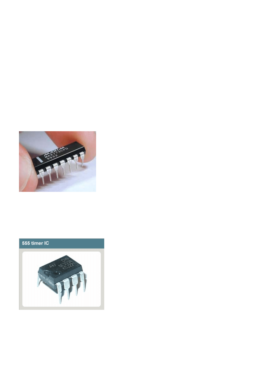
A 14-pin dual-in-line integrated circuit
The chip inside an IC is usually packaged inside a piece of black plastic with tiny
pins protruding to allow connections to the circuit. In most ICs the pins are
arranged in a 'dual-in-line' (DIL) configuration, with either eight, 14 or 16 pins.
Timer circuits
Timer circuits are used to control sequences of events in electronic systems by changing the circuit from one state to another at
preset times.
One of the commonest integrated timer circuits is the 555 timer, which is produced as an eight-pin DIL package containing 25
transistors, 2 diodes and 16 resistors. The 555 can be used as either an astable timer or a monostable timer (also known as
a one-shot timer).
An astable timer
When the astable timer is switched on it will give a constant on/off digital output. So the timer will make an LED flash, at a rate
determined by a capacitor in the circuit.
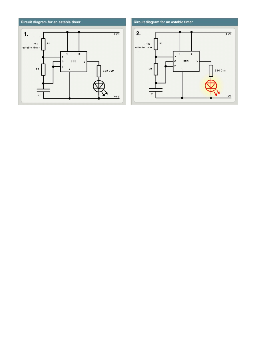
The period when the timer/LED is on is called the mark and the period when the timer/LED is off is called the space. You can
calculate the duration of the mark and the space using the following formulae:
Mark (time on) = 0.7 x (R1 + R2) x C1
Space (time off) = 0.7 x R1 x C1
- where R1 is the value of resistor R1 (in Ohms), R2 is value of resistor R2 (in Ohms) and C1 is the value of the capacitor (in
microFarads)
A monostable timer
Monostable timers are often called one-shot timers. When the timer is switched on it will stay on for a certain length of time
and then stay off until it is switched on again.
Notice how you only need to press the switch once. The switch makes contact, then the timing process begins. The time period
depends on the value of resistor R1 and capacitor C1.
The duration of the period is calculated using the formula:
Time on (seconds) = 1.1 x R1 x C1
- where R1 is the value of resistor R1 (in Ohms) and C1 is the value of the capacitor (in microFarads)
Two examples
1 An astable 555 timer has the following external component values: R1 = 100 kOhms; R2 = 47 kOhms; C1 = 10 microFarads:
•
Mark (time on) = 0.7 x (100,000 + 47,000) x 0.00001 = 1 second
•
Space (time off) = 0.7 x 100,000 x 0.00001 = 0.7 seconds
2 A monostable 555 timer has the following component values: R1 is 100 kiloOhms and C1 is 100 microFarads. Calculate the
length of time that the timer will stay on.
•
Time on = 1.1 x 100 000 x 0.0001 = 11 seconds
Operational amplifiers
Amplifiers are devices which takes a relatively weak signal as an input and produce a much stronger signal as an output.
The operational amplifier or op-amp is a special kind of amplifier used in equipment such stereo equipment and medical
cardiographs (which amplify the heart beat). They have a gain of 100,000.
Op-amps are integrated circuits that cram the equivalent of many transistors, resistors and capacitor into a small silicon chip.
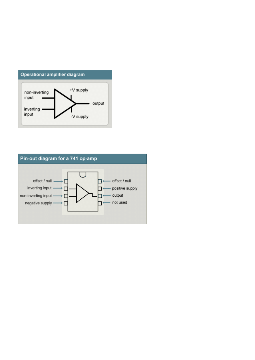
They are represented in circuit diagrams as follows:
An op-amp has two separate inputs - the inverting input and the non-inverting input. The op-amp most commonly used in
schools is the 741 op-amp, an eight-pin DIL package which apart from its code number is identical in appearance to the 555
timer. The graphic shows a pin-out diagram for a 741.
The 3 most important pins are pin 2 (inverting input), pin 3 (non-inverting input) and pin 6 (output)
The operating conditions for the 741 are as follows:
•
Maximum supply voltage: 16 volts.
•
Minimum operating temperature: 0°C to 70°C.
•
Soldering temperature: 300°C.
Op-amps as comparators
Op-amps are often used as comparators - that is, devices which compare two inputs (the inverting input and the non-
inverting input).
A common comparator is the temperature controller or thermostat. Using a temperature sensor as part of the circuitry, the op-
amp is set at a particular temperature - say 20 degrees centigrade. The op-amp compares this reference temperature to the
actual environmental temperature of the room, registered on a thermistor. If there is a difference between the two
temperatures the op-amp switches on the heating system. The diagram shows an op-amp used as a temperature controller
with a thermistor providing the non-inverting input.
Counter circuits
Counter circuits record the number of times an event takes place.
The counter circuit you are most likely to come across is the 4017 decade counter IC, which can be set to count to any value
between one and 10 very quickly, over and over again. The 4017 is a complementary metal oxide semiconductor (CMOS)
integrated circuit.
A decade counter has ten outputs. When it is turned on, the counter switches from one output to the next very quickly. The
speed at which each output turns on or 'goes high' is determined by a timer connected to an input. The counter is switched on
and off using either a manual switch or with an astable 555 timer (using pin 3 on the 555 as the output).
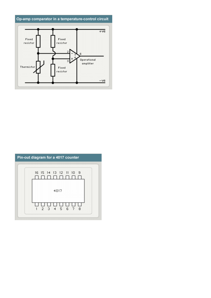
Below is a pin-out diagram showing the arrangement of pins in a 4017 counter chip, and a guide to what each pin does.
•
Pins 1 to 7 and pin 9 and pin 11 are outputs for the counter.
•
Pin 8 is the negative power supply.
•
Pin 12 is the carry-out pin (this could be connected to another 4017).
•
Pin 13 is the enable pin. It can be used to stop the count.
•
Pin 14 is the clock pin. This will be connected to a manual switch or to an astable 555 timer.
•
Pin 15 is the reset pin. This returns counter to zero.
•
Pin 16 is the positive power supply pin. It runs at a voltage between 3V and 16V.
Document Outline
Wyszukiwarka
Podobne podstrony:
Lessons in Electric Circuits Vol 5 Reference
0 50V 2A LM10C, 0 50V 2A Bench power supply circuit diagrams, schematics, electronic projects
05 Integrated High Voltage Electronics to drive Microactuators
Lessons in Electric Circuits Vol 5 Reference
US Patent 611,719 Electrical Circuit Controller
Electronique Ignition Coil Driver Circuit (Commande Bobine Haute Tension)
US Patent 609,249 Electric Circuit Controller
Mellin Transform Method for Integral Evaluation [Intro and Appln for Electromagnetics] G Fikioris (
US Patent 609,248 Electric Circuit Controller
Bearden Slides Visual Tour of what they don t want you to know about electrical circuits (www chen
[Ebook Electronics] How To Make Printed Circuit Boards
BMW E38 schematic Electrical box fan circuit
SAT Subject Physics Electric Charges, DC Circuits, Magnetism
Lessons In Electric Circuits, Volume V Reference
US Patent 609,246 Electric Circuit Controller
więcej podobnych podstron