
1 4 0 5 1 / 2
Te
Power supplies and transformers
Safety and isolation transformers (25 to 2500 VA)
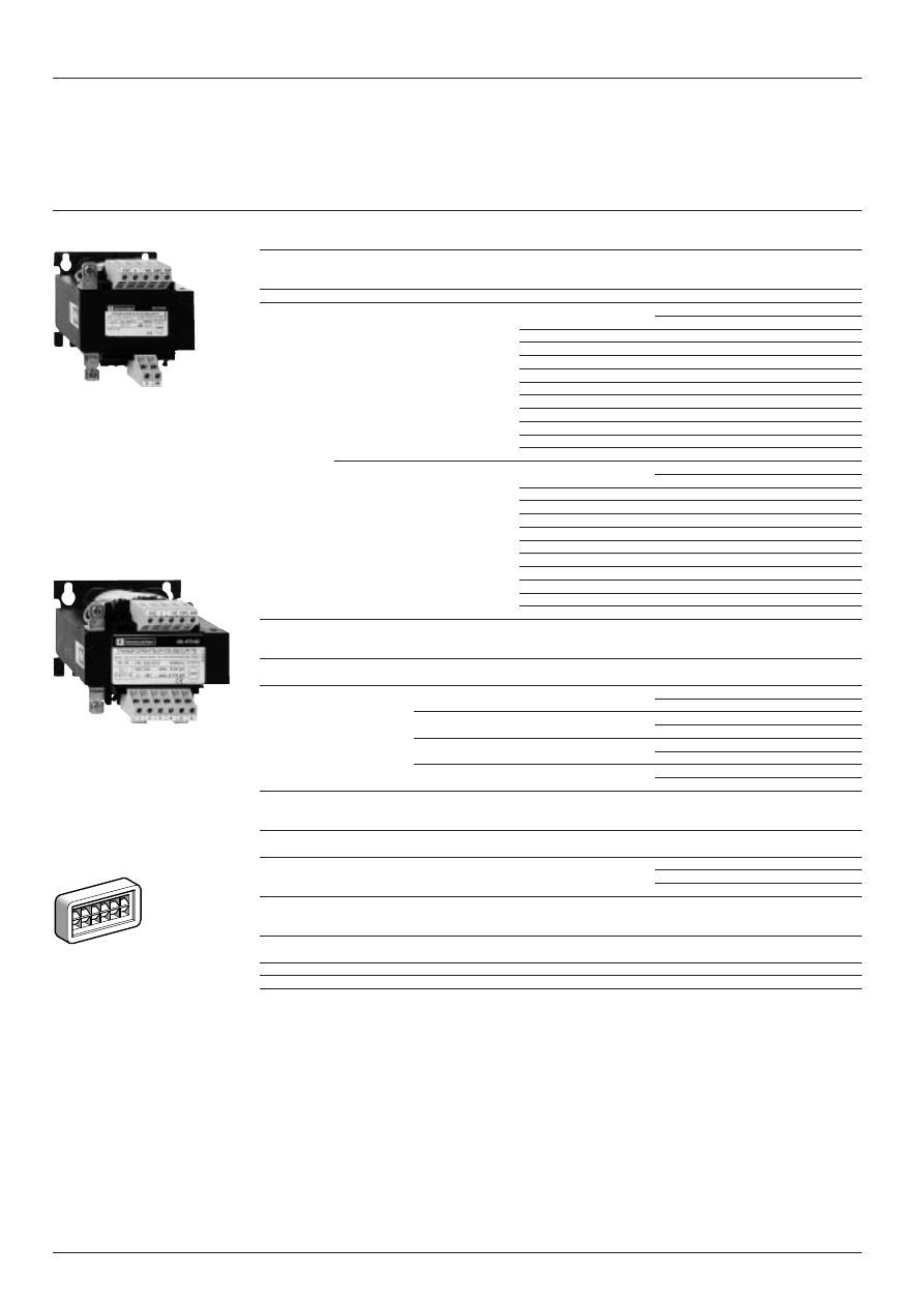
Presentation
Presentation
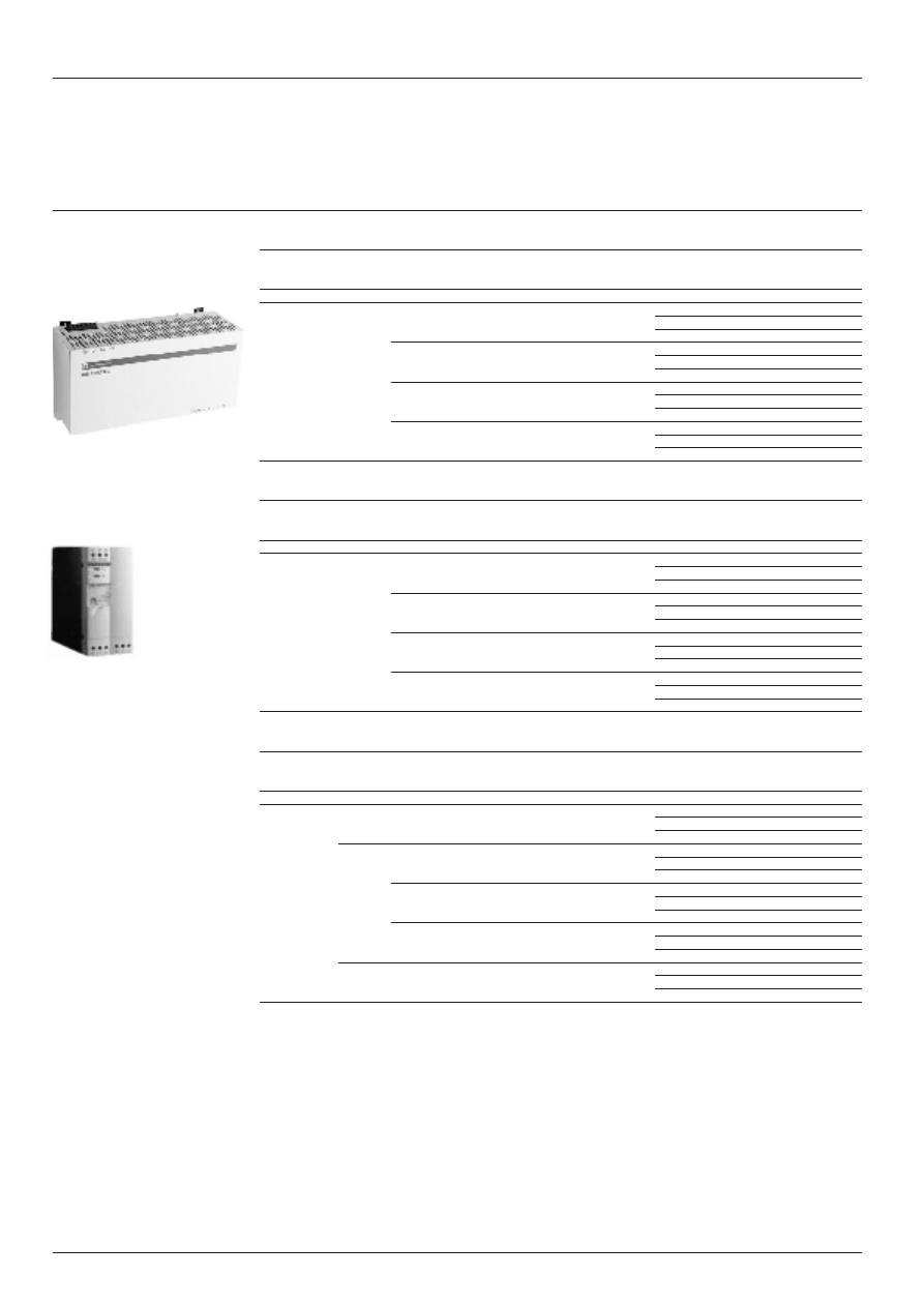
The ABL-6T range of single phase transformers is designed to supply the control circuits of electrical equipment from a
230 or 400 V supply at 50 or 60 Hz. Additional +15V and -15V connectors can provide better adaptation to the local network
if necessary.
ABL-6T transformers ensure electrical isolation between the supply and application. The entire range is fitted with an earth
screen in order to reduce the spreading of electromagnetic interference and increase user safety. ABL-6T transformers
are protection class I and are supplied with no housing, degree of protection IP 20.
They conform to EN 60 742, IEC 742 standards and are UL approved.
They are manufactured to insulation classification B or F depending on the product.
The windings are vacuum impregnated with solvent free resin.
The maximum operating temperature is 60
°
C without derating.
Connections
The product range makes it possible to cover a power range from 25 to 2500 VA.
All products have a 230/400 V +/- 15V dual voltage primary and are available in standard versions with voltages for 12,
24, 48, 115 and 230 V control circuits.
ABL-6T transformers are available as a single secondary winding version (12, 24, 115 and 230 V) and a double secondary
winding version (2 x 24 or 2 x 115 V) to enable series (to obtain 48 or 230 V) or parallel connections.
Protection
The transformers can be protected against short-circuits using fuses or thermal magnetic circuit-breakers mounted on
the secondary winding.
To operate according to UL standards, short-circuit protection must be achieved using fuses (with UL approval) on the
primary.
Where the control circuit is isolated from the earth (IT scheme), a earth leakage detector will indicate any accidental
isolation fault (see “Measurement and control relays” catalogue n
°
29709).
Characteristics :
page 14051/4
References :
page 14052/2
Dimensions :
page 14052/3
Schemes :
page 14052/3
1 4 0 5 1 / 3
Te
Power supplies and transformers
Safety and isolation transformers (25 to 2500 VA)
Selection
Selection
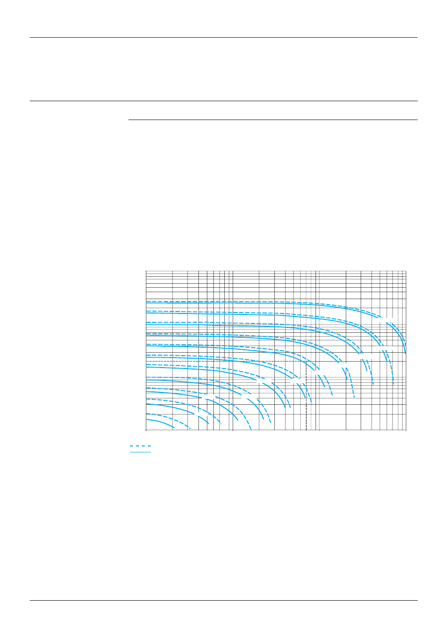
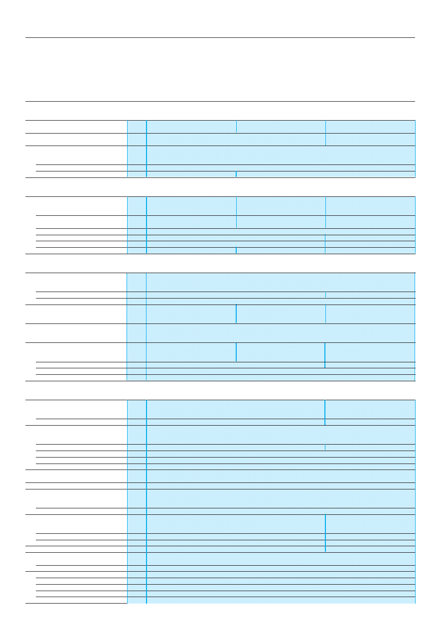
ABL-6T transformers are characterised by the apparent nominal power which they can supply continuously. But they are
also designed to supply, when necessary, much higher powers, such as contactor inrush peaks.
Contactor inrush peaks can reach 10 to 20 times the required holding current. This leads to the transformer being
oversized in relation to the continuous power it is to supply. The transformer must be sized so that the voltage drop at
its terminals, caused by the inrush, remains within the permissible limits for the contactor to close properly.
The two power values which need to be taken into account to determine which transformer rating to use are thus
- the continuous power which the transformer is to supply
- and the maximum inrush current which it must provide.
In practice, only the sum of the holding currents and the largest contactor inrush current need to be considered.
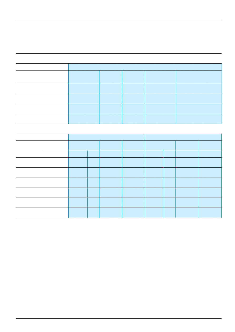
For Telemecanique transformers, the graph below can be used to select the rating to use according to these two currents.
This ensures a maximum voltage drop of 5 % at the moment of the inrush, compatible with correct operation of the entire
installation. However, these transformers have been designed for continuous operation at nominal load and at an ambient
temperature of 60
°
C. A reduction in the ambient temperature may uprate the transformer which, in some cases, enables
a lower rating to be used.
The graph below has therefore been drawn for 40 and 60
°
C.
The inrush values of the contactor coils are given in the contactor control circuit characteristics pages.
Operation at 40
°
C
Operation at 60
°
C
Example : A device with a total holding current of 200 VA and inrush current of the largest contactor of 700 VA, can be
supplied by a 630 VA transformer if it is used at an ambient temperature of 60
°
C. A 400 VA transformer is sufficient if
the ambient temperature is 40
°
C.
Characteristics :
page 14051/4
References :
page 14052/2
Dimensions :
page 14052/3
Schemes :
page 14052/3
Holding current (VA)
Inrush current (VA)
10 000
1000
10
200
100
10
100
80
1000
10 000
63 VA
160 VA
250 VA
400 VA
630 VA
1000 VA
1600 VA
2500 VA
40 VA
25 VA
100 VA
1 4 0 5 1 / 4
Te
Power supplies and transformers
Safety and isolation transformers (25 to 2500 VA)
Characteristics
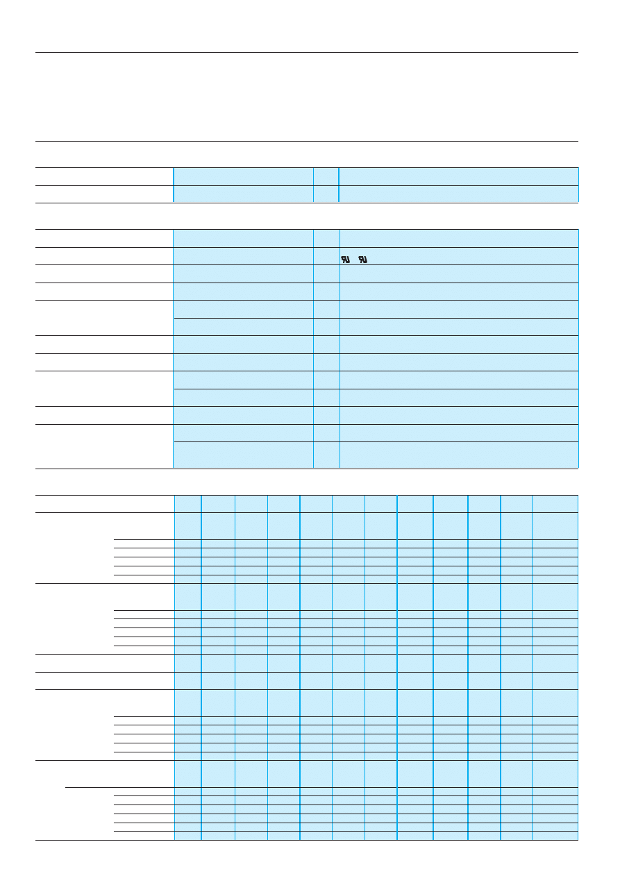
Technical characteristics
Input voltage
V
230 and 400 single phase with - 15 V and + 15 V connectors
Input frequency
Hz
47…63
Operating and environmental characteristics
Conforming to standards
EN 60742, VDE 0550-1, VDE 0550-3, UL 506, CSA C22.2 N
°
65
Certification
,c
Degree of protection
Conforming to IEC 529
IP 20
Protective treatment
“All climates”
Dielectric strength
Primary/secondary
V
4000
Winding/earth
V
2000
Protection class
I
Insulation
Class F : ABL-6T
i
ii
ii
160
i
ii
ii
and ABL-6T
i
ii
ii
250
i
ii
ii
, class B : other references
Ambient air temperature
Storage
°
C
- 40…+ 80
around device
Operation
°
C
- 20…+ 60
Operating position
Any
Mounting
Direct
Oblong holes on all models
On
(
rail
Optional mounting plate for ABL-6T
i
ii
ii
02
i
ii
ii
, ABL-6T
i
ii
ii
04
i
ii
ii
, ABL-6T
i
ii
ii
06
i
ii
ii
and ABL-6T
i
ii
ii
10
i
ii
ii
Characteristics
Power
VA
25
40
63
100
160
250
400
630
1000
1600
2500
Overvoltage
no load, hot state
ABL-6TS
ii
B
%
15
11
9
9
7
6
4
3
3
2
2
ABL-6TS
ii
G
%
15
12
9
8
6
5
4
3
3
2
3
ABL-6TS
ii
J
%
16
14
9
9
7
5
–
–
–
–
–
ABL-6TS
ii
U
%
9
9
9
9
7
5
4
3
3
3
3
ABL-6TD
ii
B
%
4
4
3
4
4
4
4
3
3
2
2
ABL-6TD
ii
G
%
9
9
9
9
7
6
4
3
3
2
3
Voltage drop
at nominal
ABL-6TS
ii
B
%
0.3
0.2
0.2
0.0
0.3
0.1
0.7
0.5
- 0.3
0.0
0.5
load
ABL-6TS
ii
G
%
0
0.4
0.1
0.6
0.7
0.7
0.5
0.3
0.5
0.1
- 0.3
ABL-6TS
ii
J
%
0.6
0
1.3
0.3
0.4
0.6
–
–
–
–
–
ABL-6TS
ii
U
%
5.9
4
1.4
0.6
0.9
0.7
0.7
0.4
5
0
0
ABL-6TD
ii
B
%
10.3
6.1
4.3
3.8
2.9
1.8
0.7
0.6
- 0.2
0.1
0.4
ABL-6TD
ii
G
%
5.9
3.6
0.5
0.2
0.4
0.3
0.4
0.3
0.1
0.3
- 0.3
Efficiency
ABL-6T
iiii
%
79
81
84
86
88
90
92
93
94
96
96
No-load losses
ABL-6T
iiii
W
3
4.4
5.3
7.1
9.1
12.5
12.4
18.9
26.5
23.7
23.4
Short-circuit voltage
ABL-6TS
ii
B
%
13.52
10.27
8.62
7.86
6.81
5.51
4.50
3.41
2.93
2.50
2.85
ABL-6TS
ii
G
%
14.03
10.71
7.92
7.51
6.65
5.28
4.66
3.47
3.04
2.45
2.61
ABL-6TS
ii
J
%
14.74
12.13
9.63
8
6.9
5.47
–
–
–
–
–
ABL-6TS
ii
U
%
14.34
11.46
9.08
8.32
7.5
5.85
4.77
3.68
3.24
2.65
8.73
ABL-6TD
ii
B
%
13.79
9.32
7.38
7.52
6.46
5.34
4.46
3.46
3.02
2.53
2.73
ABL-6TD
ii
G
%
13.34
11.08
8.30
8.05
7.15
5.63
4.58
3.53
3.16
2.57
2.65
Connections
Primary
mm
2
4
4
4
4
4
4
4
4
4
4
4
Secondary
ABL-6TD
ii
G
mm
2
4
4
4
4
4
4
4
4
4
4
4
ABL-6TS
ii
G
mm
2
4
4
4
4
4
4
4
4
4
4
10
ABL-6TS
ii
J
mm
2
4
4
4
4
4
4
–
–
–
–
–
ABL-6TS
ii
U
mm
2
4
4
4
4
4
4
4
4
4
4
4
ABL-6TD
ii
B
mm
2
4
4
4
4
4
4
4
4
10
10
10
ABL-6TS
ii
B
mm
2
4
4
4
4
4
4
10
10
10
16
35
Presentation and selection :
pages 14051/2 and 14051/3
References :
page 14052/2
Dimensions :
page 14052/3
Schemes :
page 14052/3

1 4 0 5 1 / 5
Te
Power supplies and transformers
Safety and isolation transformers (25 to 2500 VA)
Choice of protection
Protection by fuses
Recommended protection for the transformer primary
Transformer
Input voltage
Reference
Power
c
230 V single phase
c
400 V single phase
Fuse carrier/isolator
Fuse carrier/isolator
MDL fuses
aM fuses
FNQ fuses
aM fuses
UL Listed
(1)
UL Listed (1)
ABL-6T
i
ii
ii
02
i
ii
ii
25 VA
2/10 A
0.5 A
15/100 A
0.5 A
ABL-6T
i
ii
ii
04
i
ii
ii
40 VA
1/4 A
0.5 A
15/100 A
0.5 A
ABL-6T
i
ii
ii
06
i
ii
ii
63 VA
4/10 A
0.5 A
2/10 A
0.5 A
ABL-6T
i
ii
ii
10
i
ii
ii
100 VA
6/10 A
1 A
3/10 A
0.5 A
ABL-6T
i
ii
ii
16
i
ii
ii
160 VA
1 A
2 A
1/2 A
1 A
ABL-6T
i
ii
ii
25
i
ii
ii
250 VA
1 1/2 A
2 A
8/10 A
1 A
ABL-6T
i
ii
ii
40
i
ii
ii
400 VA
2 A
4 A
12/10 A
2 A
ABL-6T
i
ii
ii
63
i
ii
ii
630 VA
3 2/10 A
6 A
2 A
4 A
ABL-6T
i
ii
ii
100
i
ii
ii
1000 VA
5 A
8 A
3 A
6 A
ABL-6T
i
ii
ii
160
i
ii
ii
1600 VA
8 A
10 A
5 A
8 A
ABL-6T
i
ii
ii
250
i
ii
ii
2500 VA
2 A
16 A
7 A
10 A
Recommended protection for the transformer secondary
Transformer
Secondary 12 V
Secondary
c
24 V
Secondary
c
48 V
Secondary
c
115 V
Secondary
c
230 V
Reference
Power
Fuses
Fuses
Fuses
Fuses
Fuses
gG
T
gG
T
gG
T
gG
T
gG
T
ABL-6T
i
ii
ii
02
i
ii
ii
25 VA
2 A
2 A
1 A
1 A
0.5 A
0.5 A
–
0.2 A
–
0.1 A
ABL-6T
i
ii
ii
04
i
ii
ii
40 VA
4 A
3.15 A
1 A
1.6 A
0.5 A
0.8 A
–
0.315 A
–
0.16 A
ABL-6T
i
ii
ii
06
i
ii
ii
63 VA
6 A
5 A
2 A
2.5 A
1 A
1.25 A
0.5 A
0.5 A
–
0.25 A
ABL-6T
i
ii
ii
10
i
ii
ii
100 VA
8 A
–
4 A
4 A
2 A
2 A
0.5 A
0.8 A
–
0.4 A
ABL-6T
i
ii
ii
16
i
ii
ii
160 VA
12 A
–
6 A
–
2 A
3.15 A
1 A
1.4 A
0.5 A
0.63 A
ABL-6T
i
ii
ii
25
i
ii
ii
250 VA
20 A
–
10 A
–
4 A
5 A
2 A
2 A
1 A
1 A
ABL-6T
i
ii
ii
40
i
ii
ii
400 VA
–
–
16 A
–
8 A
–
2 A
3.15 A
1 A
1.6 A
ABL-6T
i
ii
ii
63
i
ii
ii
630 VA
–
–
25 A
–
12 A
–
4 A
5 A
2 A
2.5 A
ABL-6T
i
ii
ii
100
i
ii
ii
1000 VA
–
–
40 A
–
20 A
–
8 A
–
4 A
4 A
ABL-6T
i
ii
ii
160
i
ii
ii
1600 VA
–
–
63 A
–
32 A
–
12 A
–
6 A
–
ABL-6T
i
ii
ii
250
i
ii
ii
2500 VA
–
–
100 A
–
50 A
–
20 A
–
10 A
–
Protection by thermal magnetic circuit-breaker
Recommended protection for the transformer primary
Transformer
Input voltage
Reference
Power
c
230 V single phase
c
400 V single phase
Circuit-breaker
Circuit-breaker
Telemecanique
Merlin Gerin
Telemecanique
Merlin Gerin
(2)
1-pole
2-pole
2-pole
2-pole
ABL-6T
i
ii
ii
02
i
ii
ii
25 VA
GB2-
ii
05
24493
24494
GB2-DB05
24494
ABL-6T
i
ii
ii
04
i
ii
ii
40 VA
GB2-
ii
05
24493
24494
GB2-DB05
24494
ABL-6T
i
ii
ii
06
i
ii
ii
63 VA
GB2-
ii
05
24493
24494
GB2-DB05
24494
ABL-6T
i
ii
ii
10
i
ii
ii
100 VA
GB2-
ii
06
24565
24580
GB2-DB05
24494
ABL-6T
i
ii
ii
16
i
ii
ii
160 VA
GB2-
ii
07
24566
24581
GB2-DB06
24580
ABL-6T
i
ii
ii
25
i
ii
ii
250 VA
GB2-
ii
07
24566
24581
GB2-DB06
24580
ABL-6T
i
ii
ii
40
i
ii
ii
400 VA
GB2-
ii
08
24567
24582
GB2-DB07
24581
ABL-6T
i
ii
ii
63
i
ii
ii
630 VA
GB2-
ii
10
24568
24583
GB2-DB08
24582
ABL-6T
i
ii
ii
100
i
ii
ii
1000 VA
GB2-
ii
14
24569
24584
GB2-DB09
24583
ABL-6T
i
ii
ii
160
i
ii
ii
1600 VA
GB2-
ii
20
–
24586
GB2-DB14
24584
ABL-6T
i
ii
ii
250
i
ii
ii
2500 VA
–
–
24587
GB2-DB20
24586
Recommended protection for the transformer secondary
Transformer
Secondary 12 V
Secondary
c
24 V
Secondary
c
48 V
Secondary
c
115 V
Secondary
c
230 V
Reference
Power
Circuit-breaker (2)
Circuit-breaker (2)
Circuit-breaker (2)
Circuit-breaker (2)
Circuit-breaker (2)
ABL-6T
i
ii
ii
02
i
ii
ii
25 VA
GB2-
ii
07
24171
GB2-
ii
06
24170
GB2-
ii
05
24058
–
–
–
ABL-6T
i
ii
ii
04
i
ii
ii
40 VA
GB2-
ii
09
24173
GB2-
ii
07
24171
GB2-
ii
06
24170
–
24058
–
ABL-6T
i
ii
ii
06
i
ii
ii
63 VA
GB2-
ii
10
24174
GB2-
ii
08
24172
GB2-
ii
07
24170
GB2-
ii
05
24059
–
ABL-6T
i
ii
ii
10
i
ii
ii
100 VA
GB2-
ii
14
24175
GB2-
ii
09
24173
GB2-
ii
07
24171
GB2-
ii
06
24170
GB2-
ii
05
24058
ABL-6T
i
ii
ii
16
i
ii
ii
160 VA
–
24176
GB2-
ii
12
24174
GB2-
ii
08
24172
GB2-
ii
07
24171
GB2-
ii
06
24059
ABL-6T
i
ii
ii
25
i
ii
ii
250 VA
–
24177
GB2-
ii
16
24175
GB2-
ii
10
24174
GB2-
ii
07
24171
GB2-
ii
06
24170
ABL-6T
i
ii
ii
40
i
ii
ii
400 VA
–
–
–
24176
GB2-
ii
14
24175
GB2-
ii
08
24173
GB2-
ii
07
24171
ABL-6T
i
ii
ii
63
i
ii
ii
630 VA
–
–
–
24178
GB2-
ii
20
24176
GB2-
ii
10
24174
GB2-
ii
08
24172
ABL-6T
i
ii
ii
100
i
ii
ii
1000 VA
–
–
–
24180
–
24177
GB2-
ii
14
24175
GB2-
ii
09
24173
ABL-6T
i
ii
ii
160
i
ii
ii
1600 VA
–
–
–
24182
–
24179
GB2-
ii
20
24176
GB2-
ii
12
24174
ABL-6T
i
ii
ii
250
i
ii
ii
2500 VA
–
–
–
–
–
24181
–
24177
GB2-
ii
16
24175
(1) For operation conforming to UL.
(2) GB2-CB
ii
: 1-pole, GB2-CD
ii
: 1 pole protected and 1 pole switched, GB2-DB
ii
: 2 poles protected.
Characteristics :
page 14051/4
References :
page 14052/2
Dimensions :
page 14052/3
Schemes :
page 14052/3
1 4 0 5 2 / 2
Te
Power supplies and transformers
Safety and isolation transformers (25 to 2500 VA)
References
Transformers, dual voltage primary, with earth screen
(1)
Primary
Secondary
Output
Nominal
Basic reference
Usual
Weight
voltage
voltage
power
to be
secondary
50/60 Hz
completed (2)
voltages
V
V
VA
kg
230/400
Single
12 (J)
25
ABL-6TS02
i
(4)
J B G U
0.700
single phase winding
or
40
ABL-6TS04
i
(4)
J B G U
1.200
24 (B)
63
ABL-6TS06
i
(4)
J B G U
1.600
or
100
ABL-6TS10
i
(4)
J B G U
2.100
115 (G)
160
ABL-6TS16
i
J B G U
3.200
or
250
ABL-6TS25
i
J B G U
4.400
230 (U)
400
ABL-6TS40
i
B G U
6.500
630
ABL-6TS63
i
B G U
9.800
1000
ABL-6TS100
i
B G U
14.300
1600
ABL-6TS160
i
B G U
19.400
2500
ABL-6TS250
i
B G U
27.400
Double
24/48 (B)
25
ABL-6TD02
i
(4)
B G
0.700
winding
or
40
ABL-6TD04
i
(4)
B G
1.200
(3)
115/230 (G)
63
ABL-6TD06
i
(4)
B G
1.600
100
ABL-6TD10
i
(4)
B G
2.100
160
ABL-6TD16
i
B G
3.200
250
ABL-6TD25
i
B G
4.400
400
ABL-6TD40
i
B G
6.500
630
ABL-6TD63
i
B G
9.800
1000
ABL-6TD100
i
B G
14.300
1600
ABL-6TD160
i
B G
19.400
2500
ABL-6TD250
i
B G
27.400
Mounting accessories
(4)
Description
For
Sold in
Unit
Weight
transformers
lots of
reference
kg
Plate for mounting on
ABL-6T
i
02
i
5
ABL-6AM00
0.045
(
(
(
(
(
rail
ABL-6T
i
04
i
5
ABL-6AM01
0.050
ABL-6T
i
06
i
5
ABL-6AM02
0.055
ABL-6T
i
10
i
5
ABL-6AM03
0.065
Marking accessories
Description
Size
Sold in
Unit
Weight
mm
lots of
reference
kg
Self-adhesive
20 x 10
50
AR1-SB3
0.001
marker tag holder
(1) Separate protection and safety devices : see characteristics page 14051/3
(2) Reference to be completed with the code for the secondary voltage.
Secondary voltages available
Secondary with
Secondary with
single winding
double winding
Volts 50/60 Hz
12
24
115
230
24/48 (3)
115/230 (3)
Code
J
B
G
U
B
G
(3) 48 or 230 V, series connection (see schemes on page opposite)
(4) It is possible to order a transformer with its corresponding mounting plate. To do this, add the letter P to the reference
of the selected transformer (example : ABL-6TSO4BP)
Presentation :
page 14051/2
Characteristics :
page 14051/3
Dimensions, schemes :
page 14052/3
AR1-SB3
ABL-6TD
iii
ABL-6TS
iii
1 4 0 5 2 / 3
Te
Power supplies and transformers
Safety and isolation transformers (25 to 2500 VA)
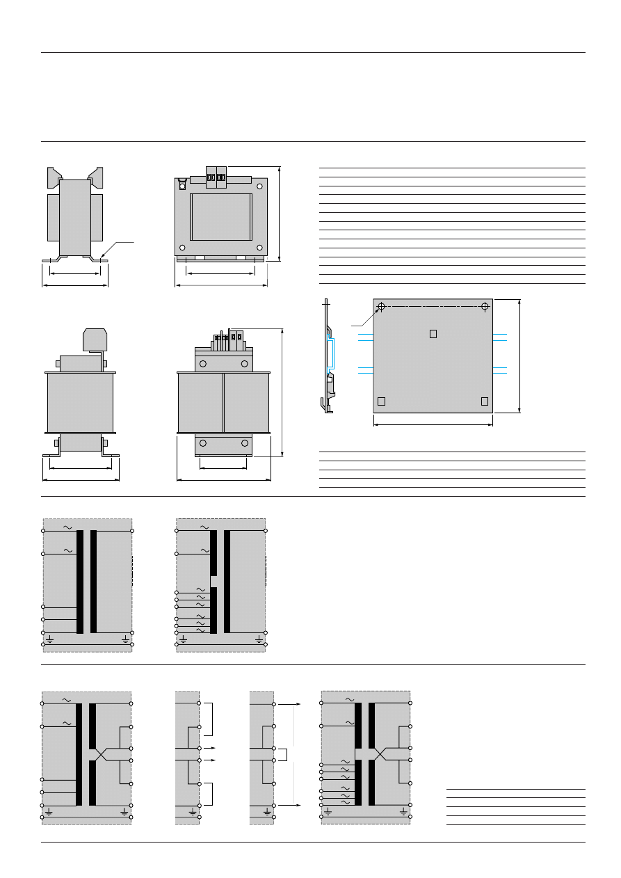
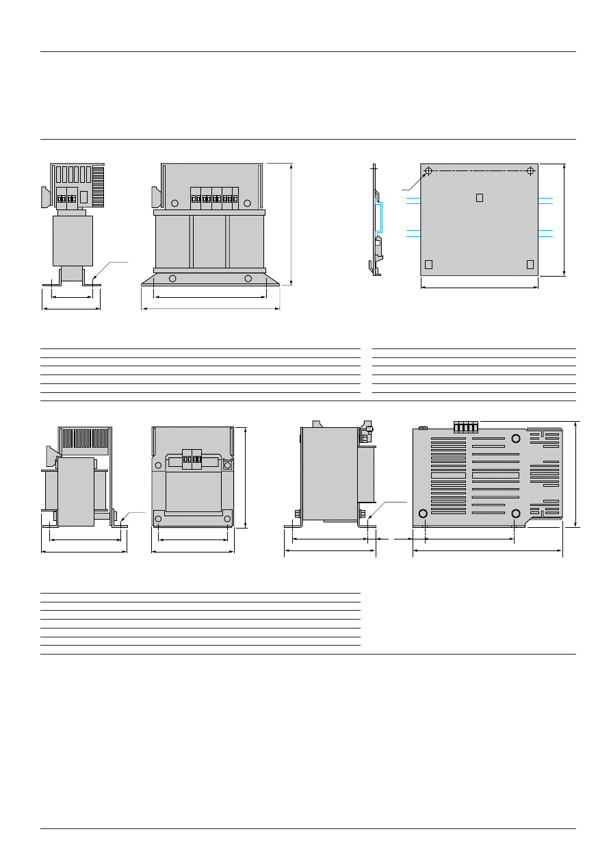
Dimensions, schemes
Dimensions
Transformers ABL-6T
i
02
i
to ABL-6T
i
100
i
ABL-
a
b
c
G
J
Ø
6T
i
02
i
66
90
55
55
42
4.8
6T
i
04
i
78
90
68
56
47.5
4.8
6T
i
06
i
78
90
80
56
56
4.8
6T
i
10
i
85
94
86
64
65.5
4.8
6T
i
16
i
106
109
81
80.5
63
5.8
6T
i
25
i
120
122
85
90
74.5
5.8
6T
i
40
i
136
140
120
104
87
5.8
6T
i
63
i
150
152
138
122
107.5
7
6T
i
100
i
174
180
146
135
111.5
7
6T
i
160
i
174
221
167
135
138
7
6T
i
250
i
198
335
145
125
117
10
Mounting plates ABL-6AM0
i
Transformers ABL-6T
i
160
i
and ABL-6T
i
250
i
ABL-
a
b
6AM00
68
70
6AM01
78
70
6AM02
78
74
6AM03
84
78
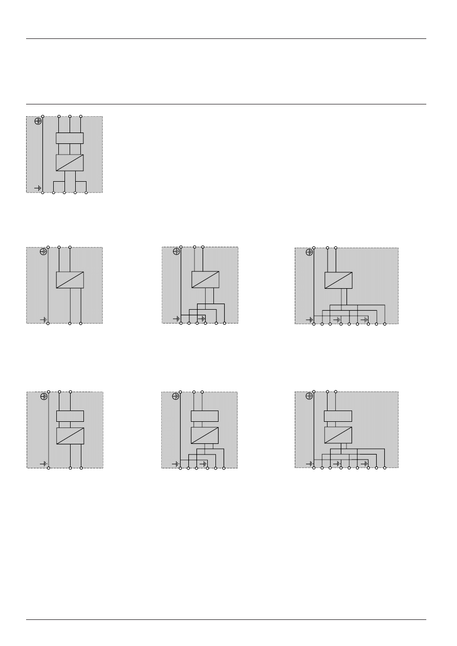
Schemes
ABL-6TS02
i
to ABL-6TS160
i
ABL-6TS250
i
ABL-6TD02
i
to ABL-6TD160
i
ABL-6TD250
i
Parallel connection
Series connection
(2) Output voltage obtained
Reference
Connection
ABL-
Parallel
Series
6TD
iii
B
24 V
115 V
6TD
iii
G
115 V
230 V
(1) Connection links are supplied with the products. The connection principle is identical for transformers ABL-6TD250
i
.
a
b
c
G
J
Presentation :
page 14051/2
Characteristics :
page 14051/3
References :
page 14052/2
b
Ø4
a
J
c
b
a
G
4 x
Ø
400 V
230 V
- 15 V
+ 15 V
0 V
0/400 V
0/230 V
240 V
220 V
230 V
420 V
380 V
400 V
1
2
3
4
5
6
1
2
3
4
5
6
(1)
(1)
(1)
U (2)
U (2)
400 V
230 V
- 15 V
1
2
3
4
5
6
+ 15 V
0 V
0/400 V
0/230 V
240 V
220 V
1
2
3
4
5
6
230 V
420 V
380 V
400 V

1 4 0 5 3 / 2
Te
Power supplies and transformers
Power supplies for d.c. control circuits
Presentation
ABL-
i
R power supplies
The ABL-
i
R range of power supplies is designed to provide the d.c. voltage necessary for the control circuits of most
control system equipment. Split into five families, this range meets all the needs encountered in industrial, commercial
and residential applications. Whether they are single-phase or 3-phase, electronic switch mode or conventional type with
rectifier, they provide a quality of output current which is suitable for the loads supplied and compatible with the mains
supply available in the equipment. Clear guidelines are given on selecting protection devices which are often used with
them, and thus a comprehensive solution is provided which can be used in total safety.
Phaseo switch mode supplies
Switch mode power supplies are totally electronic and regulated. The use of electronics makes it possible to significantly
improve the performance of these power supplies, which offer:
- compact size,
- integrated overload, short-circuit, overvoltage and undervoltage protection,
- a very wide range of permitted input voltages, without any adjustment,
- a high degree of output voltage stability,
- good performance,
- considerably reduced weight.
Phaseo power supplies are available in single-phase and 3-phase versions. They supply a voltage which is precise to 3%,
whatever the load and whatever the type of mains supply, within a range of 85 to 364 V for single-phase, or 360 to 550 V
for 3-phase. Conforming to IEC standards and UL and CSA approved, they are suitable for universal use. The inclusion
of overload and short-circuit protection makes downstream protection unnecessary if discrimination is not required.
The products are also equipped with an output undervoltage control which causes the product to trip if the output voltage
drops below 19 V, in order ensure that the voltage supplied is always usable by the actuators being supplied. All the
products are fitted with an output voltage adjustment potentiometer (in the range 24 to 28.8 V) in order to be able to
compensate for any line voltage drops in installations with long cable runs. These power supplies are designed for direct
mounting on 35 mm and 75 mm
"
rails.
These power supplies are available in single-phase and 3-phase versions and are split into three families:
i
The ABL-7RE family includes products that are excellent for typically industrial applications. They are extremely
compact and very easy to install, as well as being attractively priced.
i
The ABL-7RP family of products is more general-purpose. These supplies are fitted with an input filter (PFC) which
enables them to be used in commercial and residential environments (conforming to standard IEC 1000-3-2).
In addition, they offer two operating modes for dealing with overloads and short-circuits:
- “AUTO” mode which ensures automatic restarting of the supply as soon as the fault is cleared;
- “MANU” mode which requires the supply to be reset before restarting is possible. Resetting is achieved by switching
off the mains supply (on the product).
i
The ABL-7RU family, for use on 3-phase mains supplies, is designed for applications that include high consumption
loads. They can supply up to 960 W, in both industrial and commercial environments.
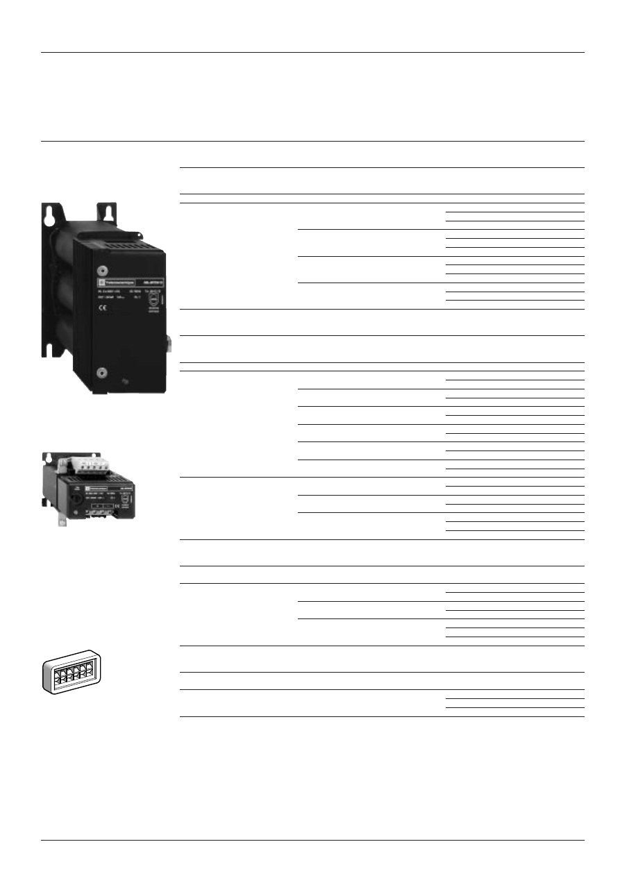
Filtered rectified power supplies
Filtered rectified power supplies are built using a safety transformer fitted with a bridge rectifier and filter capacitors.
With no regulation system, of simple and rugged construction, their output voltage will withstand mains voltage variations
and load variations while remaining within the range defined in standards IEC 1131-2. They are particularly suitable for
applications with high current inrush.
These supplies are split into two families:
i
The single-phase filtered rectified ABL-6RF family is suitable for connection to European 230/400 V and American 120/
240 V single-phase supplies. An optional mounting plate for mounting on a
"
rail, simplifies their installation.
i
The 3-phase filtered rectified ABL-6RT family is particularly suitable where a high power level is required for actuators
and preactuators. In particular, for “All
a
24 V” equipment, or for controlling d.c. valves and solenoid valves.
Characteristics :
pages 14054/2 to 14054/5
References :
pages 14056/2 and 14056/3
Dimensions :
pages 14057/2 and 14057/3
Schemes :
pages 14058/2 and 14058/3

1 4 0 5 3 / 3
Te
Power supplies and transformers
Power supplies for d.c. control circuits
Presentation
Using
a
24 V
i
Using
a
24 V enables so-called protection installations (PELV) to be built. Using PELV is a measure designed to
protect people from direct and indirect contact. Measures relating to these installations are defined in publication
NFC 12-201 and in standard IEC 364-4-41.
i
The application of these measures to the electrical equipment in machines is defined in standard NF EN 60204-1 and
requires :
- that the voltage used is below 60 V d.c. in dry environments and below 30 V in damp environments.
- the connection of one side of the PELV circuit, or one point of the source, to the equipotential protection circuit
associated with higher voltages.
- the usage of switchgear and control gear on which measures have been taken to ensure "safety separation" between
power circuits and control circuits.
i
A safety separation is necessary between power circuits and control circuits in PELV circuits. Its aim is to warn of the
appearance of dangerous voltages in
a
24 V safety circuits.
i
The reference standards involved are :
- IEC 742, EN 60742, DIN/VDE 0551 T1 (safety transformers).
- IEC 664 (coordination of isolation).
Telemecanique power supplies meet these requirements.
i
Moreover, to ensure that these products will operate correctly in relation to the demands of the reinforced isolation, it
is recommended that the products be mounted and wired as indicated below :
- they should be placed on an earthed mounting plate or rail,
- they should be connected using flexible cables, with a maximum of two wires per connection, and tightening to
nominal torque,
- conductors of the correct insulation class must be used.
i
If the d.c. circuit is not connected to an equipotential protection conductor, an earth leakage detector will indicate any
accidental insulation faults (see catalogue “Measurement and control relays" n
°
29709).
Operating voltage
i
The acceptable tolerances for the operating voltage are listed in publications IEC 1131-2 and DIN 19240.
i
For nominal voltage Un =
a
24 V, the extreme operating values are from - 15 % to + 20 % of Un, whatever the supply
variations may be in the range - 10 % to + 6 % (defined by standard IEC 38) and load variations in the range In 0-100%.
Consequently the values are as follows :
- maximum voltage (peak) : 30 V
- nominal voltage : 24 V
- minimum voltage (peak) : 19.2 V
All Telemecanique
a
24 V supplies have been designed to provide a voltage within this range.
i
It may be necessary to use a voltage measurement relay to detect when the normal voltage limits are being surpassed
and to deal with the consequences of this (see catalogue n
°
29709).
Characteristics :
pages 14054/2 to 14054/5
References :
pages 14056/2 and 14056/3
Dimensions :
pages 14057/2 and 14057/3
Schemes :
pages 14058/2 and 14058/3

1 4 0 5 3 / 4
Te
Power supplies and transformers
Power supplies for d.c. control circuits
Selection
Selection of power supplies
The characteristics to be taken into account when selecting a power supply are :
- the required output voltage and current,
- the mains voltage available in the installation.
An initial selection can be made using the table below.
This may however result in several products being selected as suitable.
Other selection criteria must therefore be taken into account.
i
The quality of the mains power supply
Filtered rectified power supplies provide a non-regulated voltage, sensitive to load and mains power supply fluctuations.
They can only be used where a good quality mains supply is available, with fluctuations limited to -10%...+10% of the
nominal value.
Graphs showing the output voltage as a function of the rated current of the load and the input voltage for ABL-6RF and
ABL-6RT supplies are given on page 14054/5.
If the quality of the mains supply is not suitable for a rectified power supply, a regulated supply must be used.
The Phaseo range is the solution because it guarantees precision to 3% on the output voltage, whatever the load current
and the input voltage. In addition, the wide input voltage range of Phaseo power supplies allows them to be connected
to all mains supplies within the nominal range, without any adjustment.
The Phaseo RP family can also be connected to
a
110 and 220 V emergency supplies.
i
Harmonic pollution (power factor)
The current drawn by a power supply is not sinusoidal. This leads to the existence of harmonic currents which pollute the
mains supply. European standard EN 61000-3-2 limits the harmonic currents produced by power supplies. This standard
covers all devices of more than 75 W, drawing up to 16 A per phase, and connected directly to the public mains power
supply. Devices connected downstream of a private, low voltage, general transformer are therefore excluded.
By design, rectified power supplies produce very little harmonic current and can therefore be used on the public mains
supply. However, switch mode supplies produce much more harmonic current and a filter circuit (Power Factor Correction
or PFC) must therefore be added to comply with standard EN 61000-3-2.
Power supplies ABL-6RF, ABL-6RT and Phaseo ABL-7RP and ABL-7RU conform to standard EN 61000-3-2 and can
therefore be connected directly to public mains power supplies.
i
Behaviour in the event of short-circuits
In the event of an overload or short-circuit, rectified power supplies must be protected by an upstream fuse or circuit
breaker to prevent their destruction. Models ABL-6RF2401, ABL-6RF2402 and ABL-6RF2405 are fitted, as standard, with
a 5 mm x 20 mm glass fuse.
Phaseo power supplies, on the other hand, are fitted with electronic protection. This protection automatically resets as
soon as the fault is cleared, so avoiding the need to take action or replace a fuse. In addition, with the Phaseo RP range,
the user can select the reset method in the event of a fault:
- in the "AUTO" position, resetting is automatic,
- in the "MANU" position, resetting will take place after the fault has been cleared and after the mains power has been
switched off and back on (on the power supply). This feature means that Phaseo RP can be used in installations where
the risks associated with sudden restarting are high.
Characteristics :
pages 14054/2 to 14054/5
References :
pages 14056/2 and 14056/3
Dimensions :
pages 14057/2 and 14057/3
Schemes :
pages 14058/2 and 14058/3

1 4 0 5 3 / 5
Te
Power supplies and transformers
Power supplies for d.c. control circuits
Selection
Selection table according to application characteristics
Technology
Regulated switch mode
Filtered rectified
Rated mains supply voltage
c
100...240 V 50/60 Hz
100...240 V
3x400...500 V 120-240 V
230-400 V
3x400 V
±
15 V
±
15 V
±
15 V
a
100... 250 V
50/60Hz
50/60 Hz
50/60 Hz
50/60 Hz
50/60 Hz
Wide range
Wide range
Wide range
Permissible variation
85...264 V, 47...63 Hz
85...264 V
360...550 V
+/-10 %
a
85...250V
47...63 Hz
47...63 Hz
47...63 Hz
Output voltage
12 V
48 V
24 V
24 V
Output current
1 A
ABL-
ABL-
6RF2401G2
6RF2401
2 A
ABL-
7RE2402
2.5 A
ABL-
ABL-
6RF2402G2
RF2402
3 A
ABL-
ABL-
ABL-
7RP4803
7RP2403
7RE2403
5 A
ABL-
ABL-
ABL-
ABL-
ABL-
7RP1205
7RP2405
7RE2405
6RF2405G2
6RF2405
10 A
ABL-
ABL-
ABL-
ABL-
ABL-
7RP2410
7RE2410
7RU2410
6RF2410
6RT2410
15 A
ABL-
6RF2415
20 A
ABL-
ABL-
ABL-
7RU2420
6RF2420
6RT2420
30 A
ABL-
ABL-
7RU2430
6RT2430
40 A
ABL-
ABL-
7RU2440
6RT2440
EN61000-3-2
Yes
No
Yes
Yes
Yes
Integrated protection
Yes
Yes
Yes from 1 to 5 A by fuse
No
Automatic or manual restart
Automatic restart
No above 5 A
Fault memory
Yes
No
No
Not applicable
Not applicable
Reference
ABL-7RP
ABL-7RE
ABL-7RU
ABL-6RF
ABL-6RT
Presentation :
pages 14053/2 and 14053/3
Characteristics :
pages 14054/2 to 14054/5
References :
pages 14056/2 and 14056/3
Dimensions :
pages 14058/2 and 14057/3
1 4 0 5 4 / 2
Te
Power supplies and transformers
Power supplies for d.c. control circuits
Phaseo regulated switch mode power supplies
Characteristics
Technical characteristics
Type of power supply
ABL-7RE
ABL-7RP
ABL-7RU
Approvals
UL508, CSA 22.2 n
°
950, TÜV
UL508, CSA 22.2 n
°
950
Conforming to standards
Safety
IEC 950
EMC
EN50081- 2, IEC61000-6-2 (EN50082-2)
Low frequency harmonic currents
–
EN61000-3-2
Input circuit
Input voltages
Rated values
V
c
100...240
c
100...240,
a
110...220
3 x
c
400...500
Permissible values
V
c
85…264 single-phase
c
85…264 single-phase
c
360…550 3-phase
a
99... 250
Permissible frequencies
Hz
47…63
Efficiency at nominal load
> 85 %
> 90 %
Current at switch-on
A
< 30
< 10
Power factor
c
0.65
c
0.98
c
0.70
Output circuit
Precision
Output voltage
Adjustable, from 100 to 120 %
Line and load regulation
±
3 %
±
1 %
Residual ripple - interference
mV
< 200
Micro-breaks
Holding time at I max and
Ve min
ms
> 10
> 20
> 3.3
Overloads
Permissible peak current
Unlimited for 100 ms
Protection
Permanent/automatic
Permanent/automatic restart or
Permanent/automatic
Short-circuit
restart
manual restart on product
restart
Overload
1.1 In
1.1 In
Overvoltage
Tripping if U > 1.5 Un
Undervoltage
Tripping if U < 0.8 Un
Operational and environmental characteristics
Connections
input
mm
2
2 x 2.5 + earth
3 x 2.5 + earth
output
mm
2
2 x 2.5 + earth, multiple output, depending on model
4 x 10 + earth
Ambient conditions
Storage temperature
°
C
- 25... + 70
Operating temperature
°
C
0... + 60
°
C (derating as from 55
°
C)
0... + 60
Maximum relative humidity
95 % without condensation or dripping water
Degree of protection
IP 20 conforming to IEC529
Vibrations
Conforming to EN61131-2
Operating position
Vertical
MTBF
> 100 000 h (Conforming to Bell Core, at 40
°
C)
Connections
Series
Possible
Parallel
Possible (maximum temperature 50
°
C)
Dielectric strength
Input/output
3000 V/50 Hz 1 min
3750 V/50 Hz 1 min
Input/earth
3000 V/50 Hz 1 min
3500 V/50 Hz 1 min
Output/earth (and output/output)
500 V/50 Hz 1 min
500 V/50 Hz 1 min
Input fuse incorporated
Yes, not interchangeable
No
Emissions
EN50081-1 (Generic)
Conducted/radiated
EN55011/EN55022 cl.B
Immunity
IEC61000-6-2 (Generic)
Electrostatic discharge
EN61000-4-2 (4 kV contact/8 kV air)
Electromagnetic
EN61000-4-3 level 3 (10 V/m)
Conducted interference
EN61000-4-4 level 3 (2 kV) , EN61000-4-5, EN61000-4-6 level 3, EN61000-4-8 level 4.
Mains interference
EN1000-4-11 (Voltage drops and cuts)
Presentation :
pages 14053/2 and 14053/3
References :
pages 14056/2 and 14056/3
Dimensions :
pages 14057/2 and 14057/3
Schemes :
pages 14058/2 and 14058/3
1 4 0 5 4 / 3
Te
Power supplies and transformers
Power supplies for d.c. control circuits
Rectified power supplies
Characteristics
Type of power supplies
ABL-6RT
ABL-6RF
2410 2420 2430 2440 2401
iiiii
2402
iiiii
2405
iiiii
2410 2415
2420
Technical characteristics
Input
All products:
Input voltages
Permissible values
V
400 3-phase (- 10…+ 10 %) 230 or 400 single-phase (- 10… +10 %)
with + 5 % and - 5 %
with - 15 V and + 15 V connectors
connectors
except ABL-6RF24
ii
G2 :
120 or 240 single-phase (- 10… +10 %)
with - 15 V and + 15 V connectors
Permissible frequencies
Hz
47…63
47…63
Efficiency (1)
%
73
78
77
78
71
75
75
80
80
93
Output
Precision
Output voltage
V
24 nominal
24 nominal
Min : 20.4; Max : 28.8
Min : 20.4; Max : 28.8
Output current
A
10
20
30
40
1
2.5
5
10
15
20
Residual ripple (1)
≤
2 %
≤
5 %
Protection
Overload and short-circuit
External, depending on
External, depending on output current,
output current
except ABL-6RF2401
i
ii
ii
, ABL-6RF2402
i
ii
ii
,
ABL-6RF2405
i
ii
ii
: 5 x 20 internal fuse
Transient output overvoltage
Peak limiter 2 J
Peak limiter 2 J
Environment
Connections
Input
mm
2
1 x 4 + earth
1 x 4 + earth
Output
mm
2
2 x 4 + earth
2 x 4…2 x 16 + earth
Ambient air temperature
Storage
°
C
- 40…+ 80
around the device
Operation
°
C
- 25…+ 60
Maximum relative humidity
90 % without condensation or dripping water
Degree of protection
IP 20
Protective treatment
“TC”
Operating position
All positions
Vertical
Dielectric strength
Input/output
V
c
4000
Input/earth
V
c
2000
Output/earth
V
c
2000
Connections
Series
Possible
Parallel
Possible, with 20 % derating
Conforming to standards
EN 60742; UL 1950; IEC 1131-2; CSA-C22.2 N
°
234 or 950
DIN 19240
Approvals
, c
(1) At nominal input voltage and load
Presentation :
pages 14053/2 and 14053/3
References :
pages 14056/2 and 14056/3
Dimensions :
pages 14057/2 and 14057/3
Schemes :
pages 14058/2 and 14058/3
1 4 0 5 4 / 4
Te
Power supplies and transformers
Power supplies for d.c. control circuits
Phaseo regulated switch mode power supplies
Output characteristics
Derating
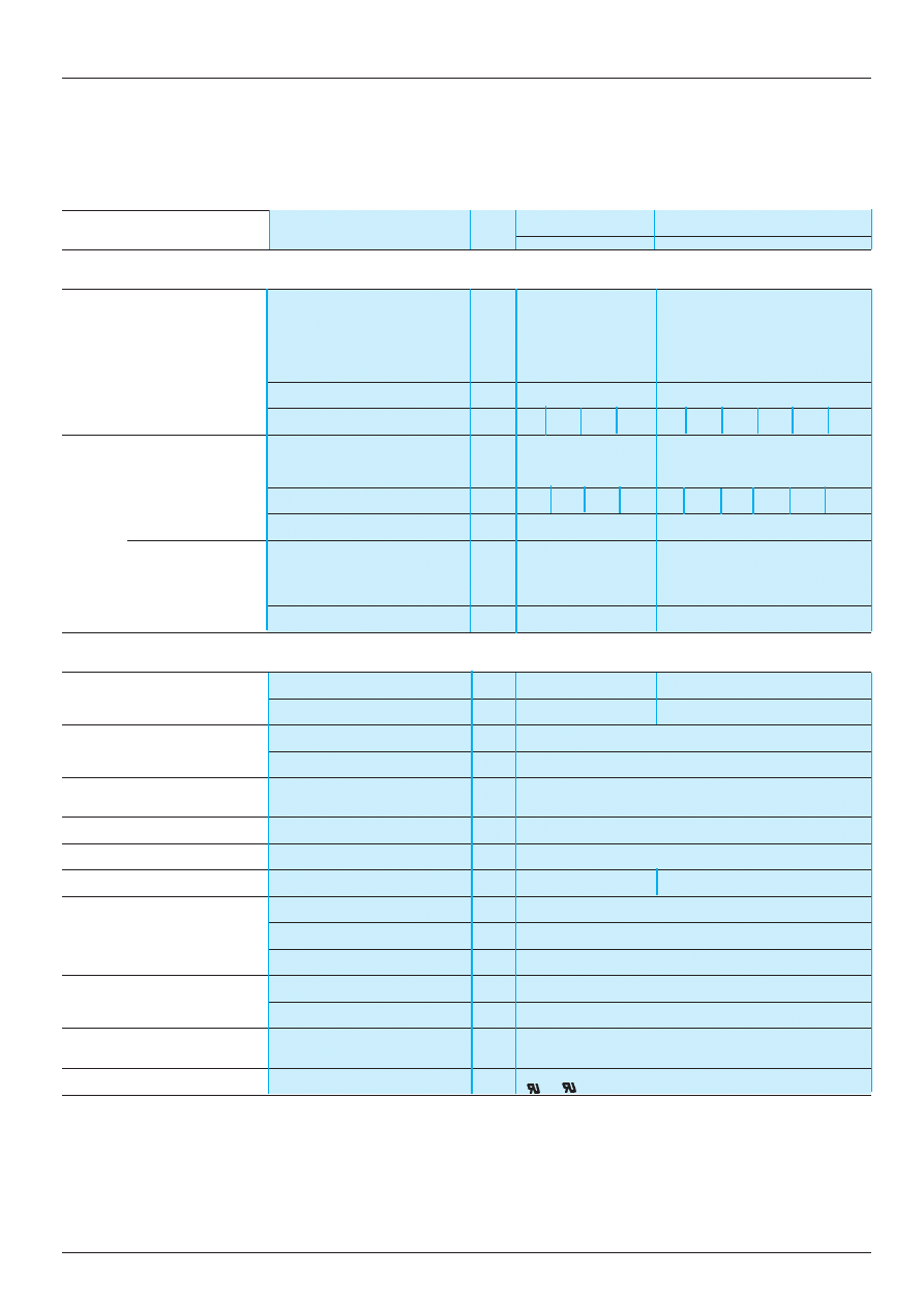
The ambient temperature is a determining factor which limits the power that an electronic power supply can deliver
continuously. A temperature which is too high around the electronic components significantly reduces their life. However,
if the ambient temperature remains largely below the rated operating temperature, then a power supply can deliver more
than its nominal power.
The rated ambient temperature for Phaseo power supplies is 50
°
C. Below this, an increase in rating is possible up to 120%
of the nominal power. Above 50
°
C, a derating is necessary up to a maximum temperature of 60
°
C.
The graph below shows the power (in relation to the nominal power) which the power supply unit can deliver continuously,
according to the ambient temperature.
Derating should be considered in the following extreme operating conditions:
- intensive operation (output current permanently close to the nominal current, combined with a high ambient temperature),
- output voltage set above 24V (to compensate for line voltage drops, for example),
- parallel connection to increase the total power.
Phaseo RE
Phaseo RP
Phaseo RU
Intensive operation
Without derating, from 0
°
C to 50
°
C
Without derating, from 0
°
C
Derating of nominal current by 1% per additional
°
C
to 60
°
C
up to 60
°
C
Rise in
The nominal power is fixed.
output voltage
Increasing the output voltage means that the current delivered must be reduced.
Parallel connection
The total power is equal to the sum of the powers of the power supplies used, but the maximum
to increase
ambient temperature for operation is 50
°
C.
the power
To improve heat dissipation, the power supplies must not be in contact with each other.
In all cases, there must be adequate convection round the products to ensure easier cooling; There must be a clear space
of 50 mm above and below Phaseo power supplies and of 15 mm at the sides.
Presentation :
pages 14053/2 and 14053/3
Characteristics :
pages 14054/2 to 14054/5
References :
pages 14056/2 and 14056/3
Dimensions :
pages 14058/2 and 14057/3
0
0
10
20
30
40
50
60
70
20
40
60
80
100
120
140
P/Pn (%)
Maximum operational temperature (
°
C)
14054/5
Te
Power supplies and transformers
Power supplies for d.c. control circuits
Rectified power supplies
Output characteristics
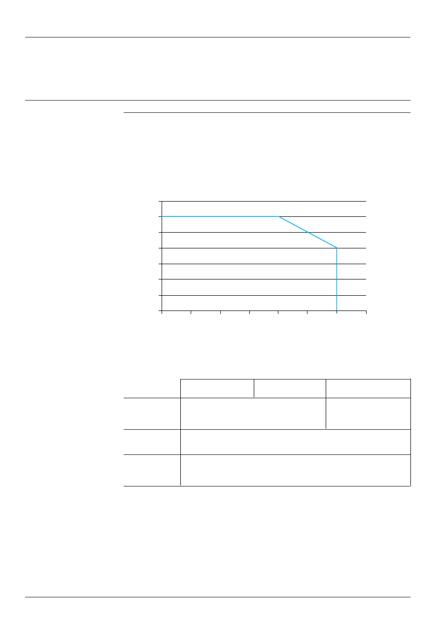
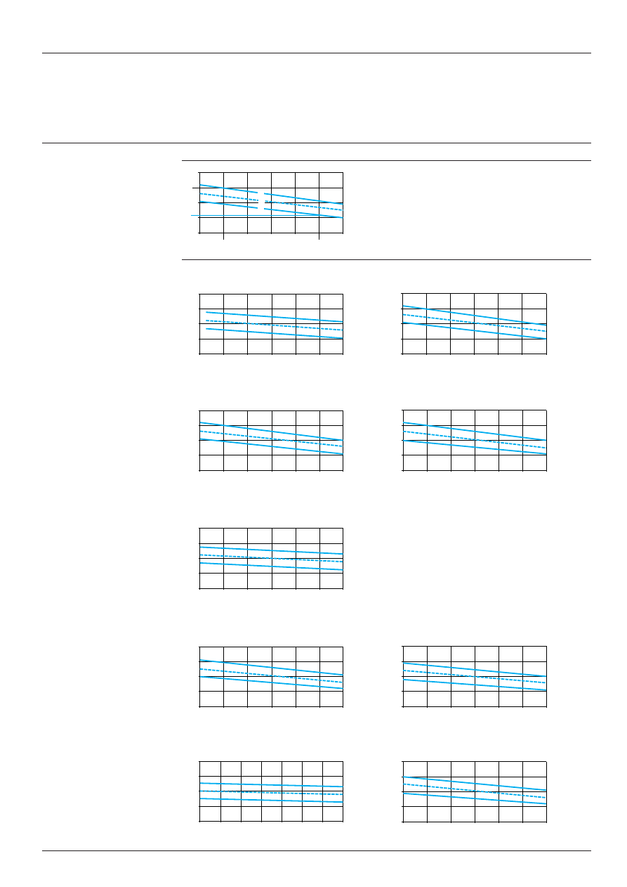
Example using the graph
For an ABL-6RF2405 power supply used with a variable load
of 1 to 5 A on a mains supply with Un
±
10%, the graph shows
the limits at the load terminals : 21 and 30 V.
Note : permitted loads are represented vertically as images
of the rated load current at rated voltage.
1
Rated supply +10%
2
Rated supply
3
Rated supply -10%
ABL-6RF2401/G2
ABL-6RF2405/G2
ABL-6RF2410
ABL-6RF2415
ABL-6RF2420
ABL-6RT2410
ABL-6RT2420
ABL-6RT2430
ABL-6RT2440
Presentation :
pages 14053/2 and 14053/3
Characteristics :
pages 14054/2 to 14054/5
References :
pages 14056/2 and 14056/3
Dimensions :
pages 14057/2 and 14057/3
15 V
0 A
1 A
2 A
3 A
4 A
5 A
6 A
20 V
25 V
30 V
35 V
15 V
0 A
8 A
16 A
24 A
32 A
40 A
48 A
20 V
25 V
30 V
35 V
15 V
0 A
3 A
6 A
9 A
12 A
15 A
18 A
20 V
25 V
30 V
35 V
15 V
0 A
5 A
10 A
15 A
20 A
25 A
30 A
35 A
20 V
25 V
30 V
35 V
15 V
0 A
0,2 A
0,4 A
0,6 A
0,8 A
1 A
1,2 A
20 V
25 V
30 V
35 V
15 V
0 A
4 A
8 A
12 A
16 A
20 A
24 A
20 V
25 V
30 V
35 V
15 V
0 A
2 A
4 A
6 A
8 A
10 A
12 A
20 V
25 V
30 V
35 V
15 V
0 A
4 A
8 A
12 A
16 A
20 A
24 A
20 V
25 V
30 V
35 V
15 V
0 A
8 A
16 A
24 A
32 A
40 A
48 A
20 V
25 V
30 V
35 V
15 V
0 A
1 A
2 A
3 A
4 A
5 A
6 A
25 V
30 V
21 V
35 V
1
2
3
Rated load current (at
a
24 V)

1 4 0 5 5 / 2
Te
Power supplies and transformers
Power supplies for d.c. control circuits
Upstream protection for Phaseo regulated switch mode power supplies
Selection
ABL-7RU, ABL-7RE and ABL-7RP power supplies: protection of the power supply line
Type de supply
c
c
c
c
c
400 V 3-phase
c
c
c
c
c
480 V 3-phase
Type of protection
Thermal-magnetic
Fuse
Thermal-magnetic
Fuse
circuit-breaker
circuit-breaker
3-pole
GV2-RT
C60N
GV2-RT
C60N
ABL-7RU2410
GV2-RT05
MG24532
1 A aM
GV2-RT04
MG 24532
1 A aM
adjustment 0.63
adjustment 0.5 A
ABL-7RU2420
GV2-RT06
MG24533
2 A gG
GV2-RT05
MG 24533
2 A gG
adjustment 1A
adjustment 0.8 A
ABL-7RU2430
GV2-RT06
MG24533
2 A gG
GV2-RT06
MG 24533
2 A gG
adjustment 1.2
adjustment 1 A
ABL-7RU2440
GV2-RT07
MG24534
4 A gG
GV2-RT06
MG 24534
2 A gG
adjustment 2 A
adjustment 1.5 A
Type of supply
c
c
c
c
c
115 V single-phase
c
c
c
c
c
230 V single-phase
Type of protection
Thermal-magnetic
gG fuse
Thermal-magnetic
gG fuse
circuit-breaker
circuit-breaker
Single-pole
GB2-CB
ii
2-pole
GB2-DB
ii
C60N
GB2-DB
ii
C60N
ABL-7RE2402
GB2-
i
B07
MG24517
2A
GB2-DB06
MG 24516
2 A
ABL-7RE2403
GB2-
i
B07
MG24517
2 A
GB2-DB06
MG 24516
2 A
ABL-7RE2405
GB2-
i
B08
MG24518
4 A
GB2-DB07
MG 17453
2 A
ABL-7RE2410
GB2-
i
B12
MG17454
6 A
GB2-DB08
MG24518
4 A
ABL-7RP2403
GB2-
i
B07
MG 24517
2 A
GB2-DB07
MG24516
2 A
ABL-7RP2405
GB2-
i
B07
MG24517
2 A
GB2-DB07
MG24516
2 A
ABL-7RP2410
GB2-
i
B09
MG24519
4 A
GB2-DB07
MG24516
2 A
ABL-7RP4803
GB2-
i
B07
MG24517
2 A
GB2-DB07
MG24516
2 A
Presentation :
pages 14053/2 and 14053/3
References :
pages 14056/2 and 14056/3
Dimensions :
pages 14057/2 and 14057/3
Schemes :
pages 14058/2 and 14058/3
1 4 0 5 5 / 3
Te
Power supplies and transformers
Power supplies for a.c. control circuits
Upstream protection for rectified power supplies
Selection
ABL-6RT power supplies: protection of the power supply line
Type of supply
c
c
c
c
c
400 V 3-phase
Type of protection
Thermal-magnetic
Thermal
C60N
FNQ fuse
aM fuse
3-pole
regulation
UL listed (1)
circuit-breaker
ABL-6RT2410
GV2-RT05
0.63 A
MG 24532
0.5 A T
2 A
ABL-6RT2420
GV2-RT07
1.6 A
MG 24533
1.125 A T
4 A
ABL-6RT2430
GV2-RT07
2 A
MG 24533
1.6 A T
4 A
ABL-6RT2440
GV2-RT08
2.6 A
MG 24534
2.5 A T
4 A
ABL-6RF power supplies: protection of the power supply line
Type of supply
c
c
c
c
c
230 V single-phase
400 V
c
c
c
c
c
single-phase
Type of protection
Thermal-magnetic
MDL fuse
aM fuse
Thermal-magnetic
FNQ fuse
aM fuse
circuit-breaker
UL listed (1)
circuit-breaker
UL listed (1)
Single-pole
GB2-CB
ii
–
–
–
–
–
–
–
2-pole
GB2-DB
ii
C60N
–
–
GB2-DB
ii
C60N
–
–
ABL-6RF2401
GB2-
i
B05
MG
0.315 A T
0.5 A
–
MG
0.15 A T
0.5 A
24516
24516
ABL-6RF2402
GB2-
i
B06
MG
0.63 A T
0.5 A
GB2-DB05
MG
0.3 A T
0.5 A
24516
24516
ABL-6RF2405
GB2-
i
B07
MG
1.4 A T
2 A
GB2-DB06
MG
0.6 A T
1 A
17453
24516
ABL-6RF2410
GB2-
i
B09
MG
3.15 A T
4 A
GB2-DB07
MG
1.25 A T
2 A
24519
17453
ABL-6RF2415
GB2-
i
B10
MG
5 A T
6 A
GB2-DB08
MG
2 A T
4 A
17454
24517
ABL-6RF2420
GB2-
i
B14
MG
6 A T
6 A
GB2-DB14
MG
2.5 A T
6 A
24520
24518
(1) For operation conforming to UL
Presentation :
pages 14053/2 and 14053/3
References :
pages 14056/2 and 14056/3
Dimensions :
pages 14057/2 and 14057/3
Schemes :
pages 14058/2 and 14058/3
14056/2
Te
Power supplies and transformers
Power supplies for d.c. control circuits
Phaseo regulated switch mode power supplies
References
3-phase regulated switch mode power supplies ABL-7RU
Mains
Output
Nominal
Nominal
Automatic
Complies with Reference
Weight
input voltage
voltage
power
current
protection
standard
47...63 Hz
reset
EN 61000-3-2
c
V
a
a
a
a
a
V
W
A
kg
400...500
24
240
10
auto
yes
ABL-7RU2410
2.900
3-phase
wide range
480
20
auto
yes
ABL-7RU2420
3.000
720
30
auto
yes
ABL-7RU2430 (1)
5.000
960
40
auto
yes
ABL-7RU2440 (1)
5.000
Single phase regulated switch mode power supplies ABL-7RE
Mains
Output
Nominal
Nominal
Automatic
Complies with Reference
Weight
input voltage
voltage
power
current
protection
standard
47...63 Hz
reset
EN 61000-3-2
V
a
a
a
a
a
V
W
A
kg
100…240
24
48
2
auto
no
ABL-7RE2402
0.520
single phase
wide range
72
3
auto
no
ABL-7RE2403
0.520
120
5
auto
no
ABL-7RE2405
1.000
240
10
auto
no
ABL-7RE2410
2.200
Single phase regulated switch mode power supplies ABL-7RP
Mains
Output
Nominal
Nominal
Automatic
Complies with Reference
Weight
input voltage
voltage
power
current
protection
standard
47...63 Hz
reset
EN 61000-3-2
V
a
a
a
a
a
V
W
A
kg
c
100...240
12
60
5
auto/man
yes
ABL-7RP1205
1.000
a
100...250
single phase
wide range
24
72
3
auto/man
yes
ABL-7RP2403
0.520
120
5
auto/man
yes
ABL-7RP2405
1.000
240
10
auto/man
yes
ABL-7RP2410
2.200
48
144
3
auto/man
yes
ABL-7RP4803
1.000
(1) Available : 3rd quarter 2000.
Presentation :
pages 14053/2 and 14053/3
Characteristics :
pages 14054/2 to 14054/4
Dimensions :
pages 14057/2 and 14057/3
Schemes :
pages 14058/2 and 14058/3
ABL-7RE2405
ABL-7RP2405
ABL-7RP4803
ABL-7RU2430
1 4 0 5 6 / 3
Te
Power supplies and transformers
Power supplies for d.c. control circuits
Filtered rectified power supplies
References
Three phase filtered rectified power supplies
(1)
Mains
Nominal
Nominal
Maximum
Reference
Weight
input voltage
output
power
output
50/60 Hz
voltage
current
c
c
c
c
c
V
a
a
a
a
a
V
W
A
kg
380-400-420
24
240
10
ABL-6RT2410
6.200
(
±
10%)
three phase
480
20
ABL-6RT2420
10.700
720
30
ABL-6RT2430
15.150
960
40
ABL-6RT2440
19.800
Single phase filtered rectified power supplies
(1)
Mains
Nominal
Nominal
Maximum
Protection
Reference
Weight
input voltage
output
power
output
per cartridge
50/60 Hz
voltage
current
fuse 5 x 20
c
c
c
c
c
V
a
a
a
a
a
V
W
A
kg
215-230-245
24
24
1
With
ABL-6RF2401 (2)
1.300
(
±
10%)
385-400-415
60
2.5
With
ABL-6RF2402 (2)
2.000
(
±
10%)
single phase
120
5
With
ABL-6RF2405 (2)
3.100
240
10
Without
ABL-6RF2410
6.100
360
15
Without
ABL-6RF2415
8.450
480
20
Without
ABL-6RF2420
12.300
105-120-135
24
24
1
With
ABL-6RF2401G2 (2)
1.300
(
±
10%)
225-240-255
60
2.5
With
ABL-6RF2402G2 (2)
2.000
(
±
10%)
single phase
120
5
With
ABL-6RF2405G2 (2)
3.100
Mounting accessories
Description
For
Sold in
Reference
Weight
power supplies
lots of
kg
Plate for mounting (2)
ABL-6RF2401
i
5
ABL-6AM01
0.050
on 35 mm Omega or
combination rail
ABL-6RF2402
i
5
ABL-6AM02
0.065
ABL-6RF2405
i
5
ABL-6AM04
0.085
Marking accessories
Description
Size
Sold in
Reference
Weight
mm
lots of
kg
Self-adhesive
20 x 10
50
AR1-SB3
0.010
marker tag holder
(1) Separate protection and safety device : see recommended product references page 14055/2.
(2) It is possible to order a power supply with its corresponding mounting plate. To do this, add the letter P to the reference
of the selected power supply (example : ABL-6RF2401P).
Presentation :
pages 14053/2 and 14053/3
Characteristics :
pages 14054/2 to 14054/5
Dimensions :
pages 14057/2 and 14057/3
Schemes :
pages 14058/2 and 14058/3
ABL-6RF
iiii
ABL-6RT
iiii
AR1-SB3
Te
1 4 0 5 7 / 2
Power supplies and transformers
Power supplies for d.c. control circuits
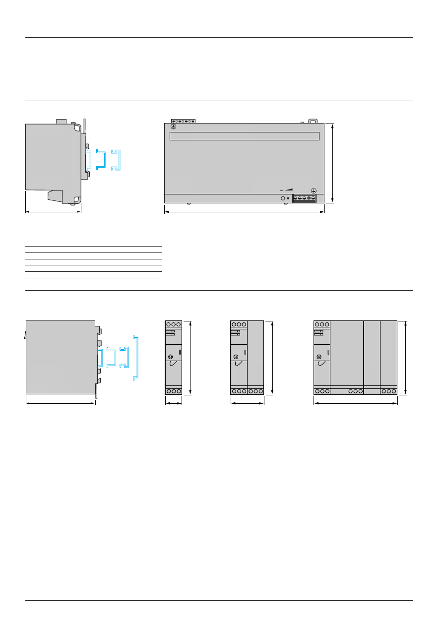
Dimensions
ABL-7RU24
i
0
ABL-7RU
a
b
c
2410
260
130
90
2420
260
130
90
2430
320
170
115
2440
320
170
115
ABL-7RE24
ii
/ABL-7RP
iiii
7RE2402/2403
7RE2405
7RE2410
Common side view
7RP2403
7RP1205/2405/4803
7RP2410
Clip-on mounting on 35 and 75 mm rails
Presentation :
pages 14053/2 and 14053/3
Characteristics :
pages 14054/2 to 14054/5
References :
pages 14056/2 and 14056/3
Schemes :
pages 14058/2 and 14058/3
c
b
a
+ + – –
L1 L2 L3
24 ...28,8VDC
ON
120
27
54
135
120
120
120
14057/3
Te
Power supplies and transformers
Power supplies for d.c. control circuits
Dimensions
ABL-6RT24
i
0
Mounting plates ABL-6AM0i
ABL-
a
b
c
G
J
Ø
ABL-
a
b
Ø
6RT2410
185
177
100
164
71.5
6.5
6AM01
78
70
4
6RT2420
220
212
121
196
79.5
8
6AM03
84
78
4
6RT2430
244
236
130
215
97
8
6AM04
96
91
5
6RT2440
284
268
143
256.5
105
11
ABL-6RF24
ii
ABL-6RF2420
ABL-
a
b
c
G
J
Ø
6RF2401
i
78
120
72
56
47.5
4.8
6RF2402
i
84
122
87
64
65.5
4.8
6RF2405
i
96
132
91
84
75.3
5.8
6RF2410
120
175
119
90
94.5
5.8
6RF2415
135
187
124
104
97
5.8
Presentation :
pages 14053/2 and 14053/3
Characteristics :
pages 14054/2 to 14054/5
References :
pages 14056/2 and 14056/3
Schemes :
pages 14058/2 and 14058/3
b
a
G
J
c
4 x Ø
J
c
b
G
a
4 x Ø
122,8
8,7
148,5
162
18,5
233
135
4 x Ø 7
b
Ø
a
1 4 0 5 8 / 2
Te
+
–
+
–
L
N
c
a
–
+
L
N
c
a
+
–
+
–
+
–
L
N
c
a
–
–
L2
L1
c
a
L3
+
+
Power supplies and transformers
Power supplies for d.c. control circuits
Schemes
ABL-7RU24
i
0
ABL-7RE2402/2403
ABL-7RE2405
ABL-7RE2410
ABL-7RP2403
ABL-7RP1205/2405/4803
ABL-7RP2410
Presentation :
pages 14053/2 and 14053/3
Characteristics :
pages 14054/2 to 14054/5
References :
pages 14056/2 and 14056/3
Dimensions :
pages 14057/2 and 14057/3
Filter
Filter
Filter
Filter
–
+
L
N
c
a
+
–
+
–
+
–
L
N
c
a
+
–
+
–
L
N
c
a
1 4 0 5 8 / 3
Te
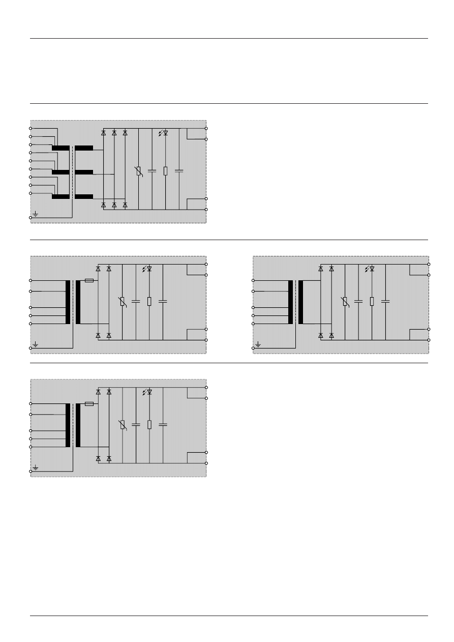
Power supplies and transformers
Power supplies for d.c. control circuits
Schemes
ABL-6RT24
i
0
ABL-6RF2401, ABL-6RF2402, ABL-6RF2405
ABL-6RF2410, ABL-6RF2415, ABL-6RF2420
ABL-6RF2401G2, ABL-6RF2402G2, ABL-6RF2405G2
Presentation :
pages 14053/2 and 14053/3
Characteristics :
pages 14054/2 to 14054/4
References :
pages 14056/2 and 14056/3
Dimensions :
pages 14057/2 and 14057/3
–
5 %
L1
+
5 %
–
5 %
L2
+
5 %
–
5 %
L3
+
5 %
0 V
0 V
+
24 V
+
24 V
400 V
230 V
–
15 V
0 V
+
15 V
0 V
0 V
+
24 V
+
24 V
F1
400 V
230 V
–
15 V
0 V
+
15 V
0 V
0 V
+
24 V
+
24 V
240 V
120 V
–
15 V
0 V
+
15 V
0 V
0 V
+
24 V
+
24 V
F1
Document Outline
- Power supplies and transformers
Wyszukiwarka
Podobne podstrony:
AGH Analog electronics Chapter IV power supplies
04 1c PHASEO POWER SUPP AND TRA Nieznany (2)
Non Intrinsic Differential Mode Noise of Switching Power Supplies and Its Implications to Filter Des
WIRING DIAGRAMS FOR POWER SUPPLIES SECTION 3 7
Power Calculator Catalog
02 ZELIO CONTROL CATALOGUE
02 ZELIO TIME CATALOGUE
02 ZELIO CONTROL CATALOGUE
02 Kuji In Mastery The Power of Manifestation by MahaVajra
Clancy Tom Power Plays 02 Sprawa Oriona 2
Clancy Tom Power Plays 02 Sprawa Oriona
Simon Brown Keys of Power 02 Fire and Sword
więcej podobnych podstron