28411/2
Te
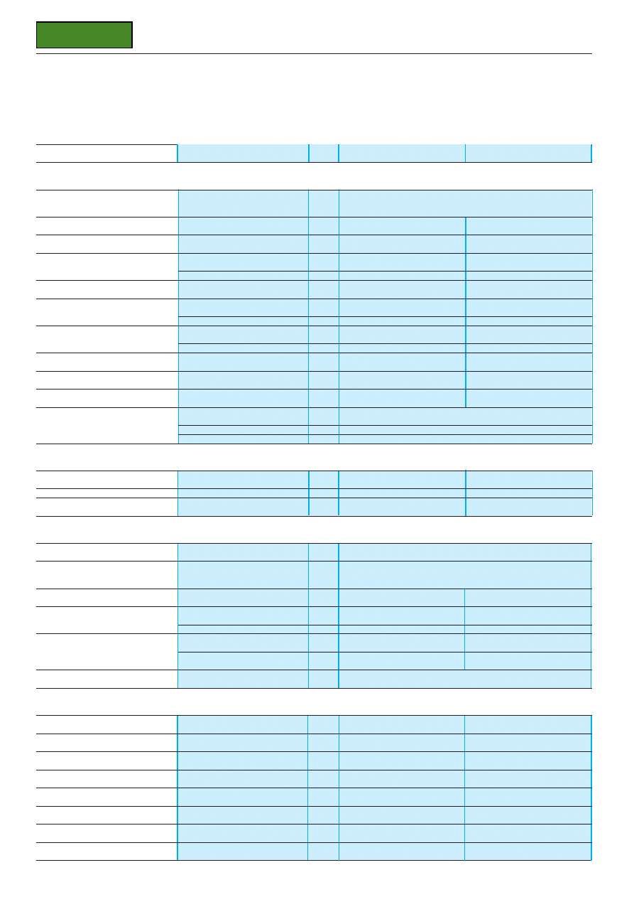
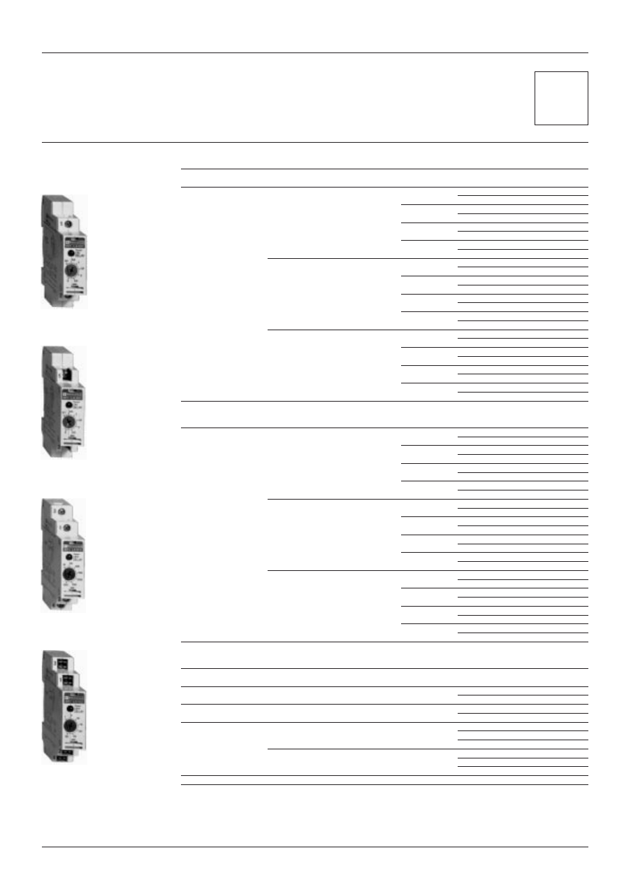
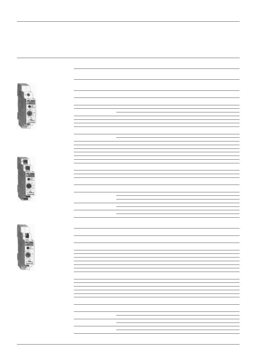
RE 1 timing relays
Solid state output, width 17.5 mm
Characteristics
T y p e
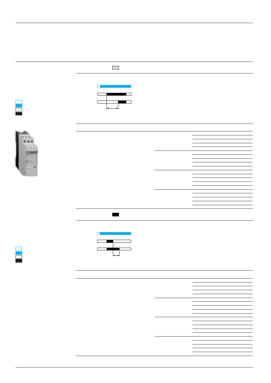
RE1-LA (On-delay)
RE1-LC (Off-delay)
Environment
Conforming to standards
IEC 144, 158-1 and 255-5, NF C 20-010, 20-040 and 63-030, VDE 0110 C
and EN 50005
Product certifications
CSA, NEMKO, SEMKO, BV
NEMKO, BV
Protective treatment
“TH”
“TH”
Ambient air temperature
Operation
°
C
- 25…+ 60
- 25…+ 60
around the device
Storage
°
C
- 40…+ 85
- 40…+ 85
Rated insulation voltage (Ui)
Conforming to IEC 158-1 and CSA
V
IEC 158-1 : 250; CSA : 300
IEC 158-1 : 250 ; CSA : 300
Vibration resistance
Severity
A
55
55
Conforming to NF C 20-616 & IEC 68-2-6 Permissible acceleration
5 gn (60…500 Hz)
5 gn (60…500 Hz)
Shock resistance
Severity
A
50
50
Conforming to NF C 20-608
Permissible acceleration
50 gn (pulse duration 11 ms)
50 gn (pulse duration 11 ms)
Degree of protection
IP 40
IP 40
Maximum operating altitude
Without derating
m
3000
3000
Operating positions
Without derating
Any position
Any position
C a b l i n g
Using cable
m m
2
1 x 0.75 to 2 x 1.5, with or without cable end; captive screw clamps
Using Faston connectors
2 x 2.8 or 2 x 6.35
Using open or closed tags
Removable screw clamps
Control circuit characteristics
Supply voltage
And permissible variation
V
c
and
a
24…240; 0.8…1.1 Un
c
24…240; 0.8…1.1 Un
F r e q u e n c y
And permissible variation
H z
50/60
±
20 %
50/60
±
20 %
Control contact
Hard-wired connection only
–
RE1-LC : connecting cable
to timer
≤
10 m
Time delay characteristics
Timing range
0.1…3 s; 1…30 s; 10…300 s; 2…60 min
Setting accuracy
0.1…300 s :
≤
10 % of the full scale
2…60 min :
≤
15 % of the full scale
Repeat accuracy
Conforming to VDE 0435
±
3 % (0…40
°
C)
±
3 % (0…40
°
C)
Reset time
Range from 0.1…300 s
m s
150 (25 after the time delay)
200
during the time delay period
Range from 2…60 min
m s
650 (25 after the time delay)
1600
Maximum immunity to
Range from 0.1…300 s
m s
10 (2 after the time delay)
20
micro-breaks during
the time delay period
Range from 2…60 min
m s
200 (2 after the time delay)
200
Time delay indication
By integral LED
LED illuminates during the time delay period
Switching characteristics (solid state type)
Maximum continuous current
At ambient
θ
: 20
°
C
A
0.7 (minimum 10 mA)
0.7 (minimum 10 mA)
Maximum short time rating
For 10 ms
A
15
15
Volt drop, “closed state”
V
3 max to 0.7 A
3 max to 0.7 A
Leakage current “open state”
m A
≤
5
≤
1
Maximum power loss
W
2.5
4
D e r a t i n g
For temperature > 20
°
C
m A
5 per
°
C
5 per
°
C
Overload protection
Conforming to IEC 255-5
3 kV 0.5 joule
3 kV 0.5 joule
In millions of
Electrical durability
operating cycles
100
100
References :
page 28411/3
Dimensions, schemes :
page 28411/4
Compatibility :
page 28411/5
28411/3
Te
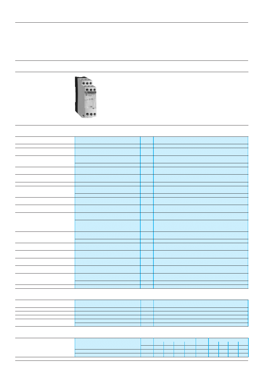
I0061/2
RE 1 timing relays
Solid state output, width 17.5 mm
References
On-delay timers
Type of
Type of
Timing
Reference
Weight
circuit
connection
range
kg
a.c. or d.c.
For cable 1 x 0.75 to 2 x 1.5 mm
2
0.1…3 s
RE1-LA001
0.055
24…240 V
with or without cable end,
recessed +/- screw clamp
1…30 s
RE1-LA002
0.055
terminals.
10…300 s
RE1-LA003
0.055
2…60 min
RE1-LA004
0.055
For open or closed tags
0.1…3 s
RE1-LA301
0.055
recessed +/- screw clamp
terminals.
1…30 s
RE1-LA302
0.055
10…300 s
RE1-LA303
0.055
2…60 min
RE1-LA304
0.055
For Faston connectors 2 x 2.8
0.1…3 s
RE1-LA101
0.055
or 2 x 6.35
1…30 s
RE1-LA102
0.055
10…300 s
RE1-LA103
0.055
2…60 min
RE1-LA104
0.055
Off-delay timers
a.c.
For cable 1 x 0.75 to 2 x 1.5 mm
2
0.1…3 s
RE1-LC011
0.055
24…240 V
with or without cable end,
recessed +/- screw clamp
1…30 s
RE1-LC012
0.055
terminals.
10…300 s
RE1-LC013
0.055
2…60 min
RE1-LC014
0.055
For open or closed tags
0.1…3 s
RE1-LC311
0.055
recessed +/- screw clamp
terminals.
1…30 s
RE1-LC312
0.055
10…300 s
RE1-LC313
0.055
2…60 min
RE1-LC314
0.055
For Faston connectors 2 x 2.8
0.1…3 s
RE1-LC111
0.055
or 2 x 6.35
1…30 s
RE1-LC112
0.055
10…300 s
RE1-LC113
0.055
2…60 min
RE1-LC114
0.055
Accessories
(to be ordered separately)
Description
Sold in
Unit
Weight
lots of
reference
kg
Lead sealing kit
10
LA9-RE01
0.005
Mounting plate
For M4 screws, 40 mm centres
10
AM1-PT01
0.020
Clip-in markers
Strip of 10 identical
25
AB1-R (1)
0.002
(5 max. per
numbers (0 to 9)
timer)
Strip of 10 identical
25
AB1-G (1)
0.002
capital letters (A to Z)
(1) To order, add the required number or letter to the end of the reference.
Other versions
Cabling by captive or removable screw clamp connections; Faston connectors.
For other information : bulk purchase, prices, delivery times, please consult your Regional Sales
Office.
c
a
o r
RE1-LC112
RE1-LC013
RE1-LA301
RE1-LA001
Characteristics :
page 28411/2
Dimensions, schemes :
page 28411/4
Compatibility :
page 28411/5
28411/4
Te
RE 1 timing relays
Solid state output, width 17.5 mm
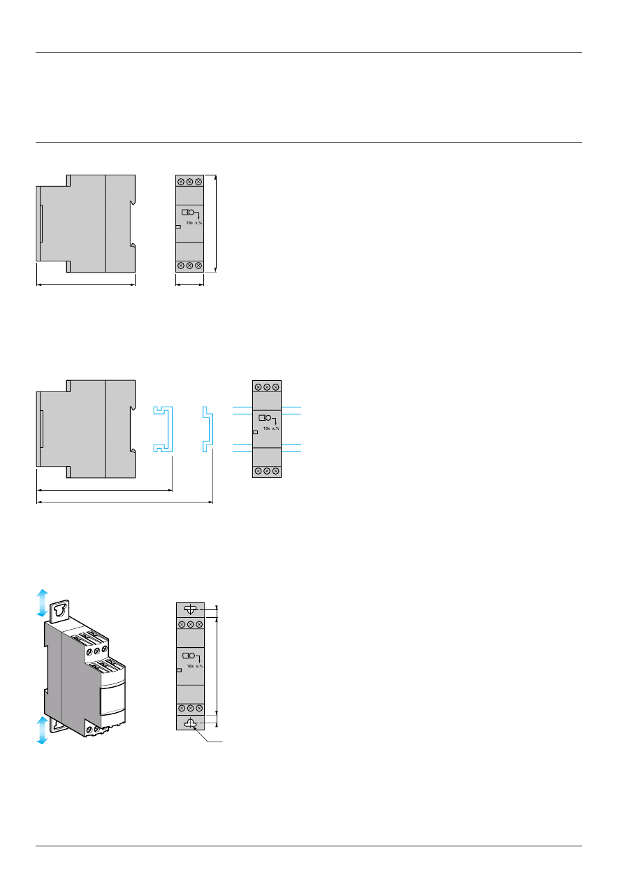
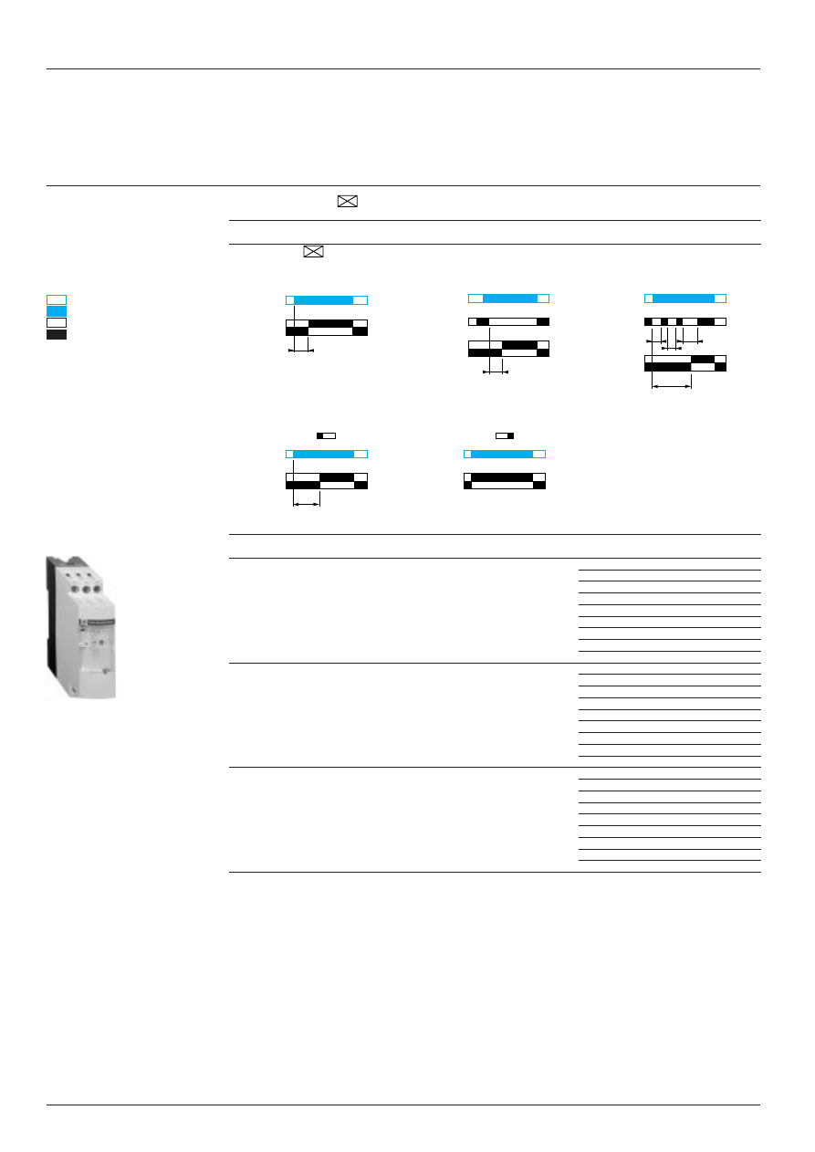
Dimensions, mounting, schemes
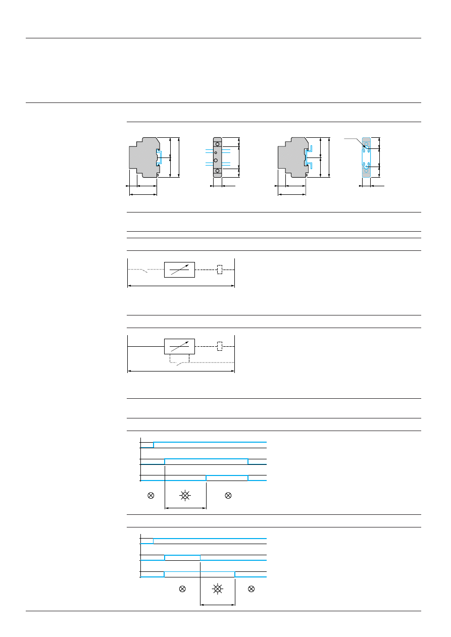
Dimensions and mounting methods for timers RE1-LA and LC
Mounting on AM1-DP200, AM1-DE200 rail
Mounting with plate AM1-PT01
(1) 60 with AM1-DP, 67.5 with AM1-DE.
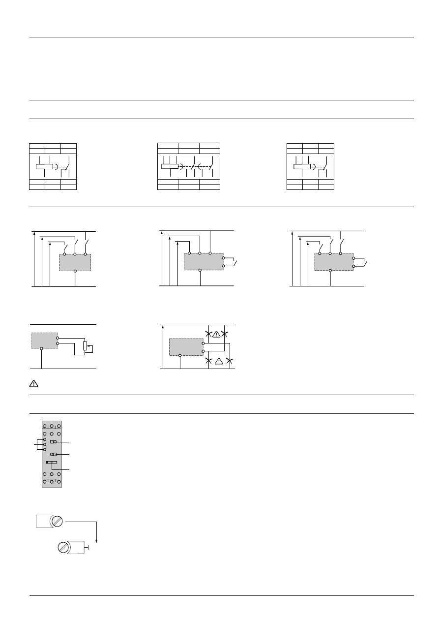
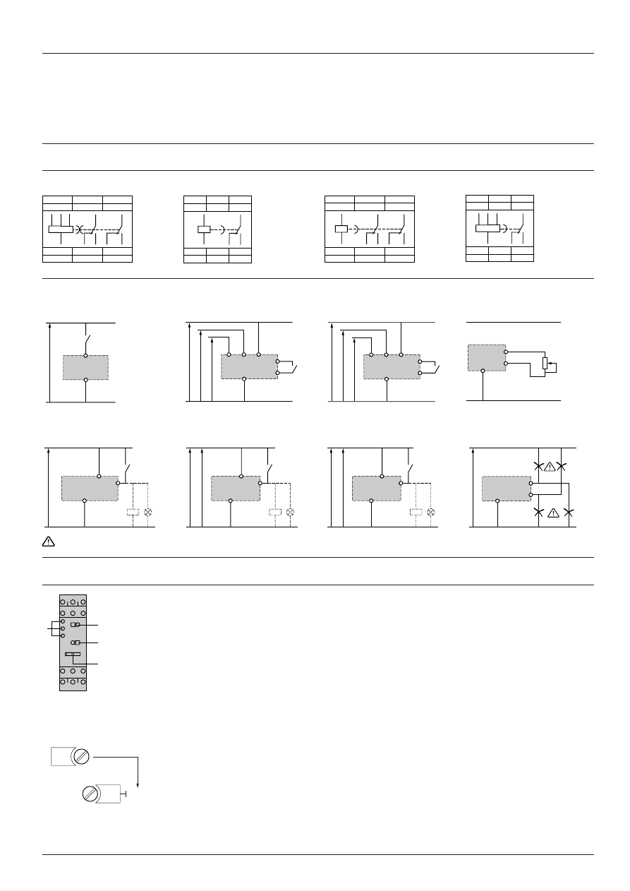
Wiring schemes
Caution : The terminal references enclosed in brackets refer to old version electronic timers.
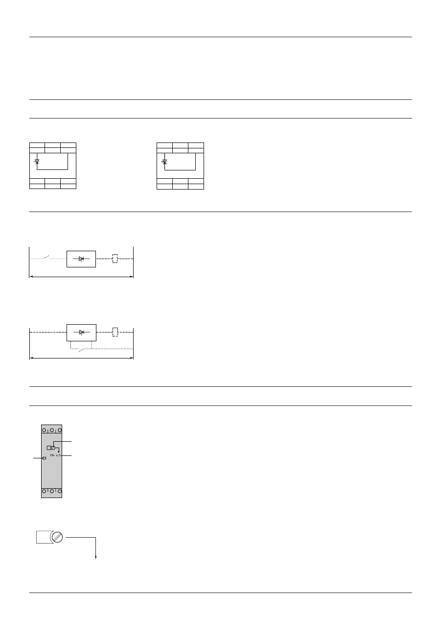
RE1-LA On-delay
The timer is connected in series between the load which
requires delayed energisation and switch K. The mains
supply can be a.c. or d.c. with any voltage between 24 V
and 240 V. (See page opposite for use of timer in conjunction
with other Telemecanique products).
RE1-LC Off-delay
The timer is connected in series with the load which
requires delayed de-energisation. Switch K is linked to
terminals Y2 and A2 of the timer and terminal A2 is linked
to the mains supply as shown in the scheme opposite. The
unit operates on a.c. current at a voltage between 24 V and
240 V. (See page opposite for use of timer in conjunction
with other Telemecanique products).
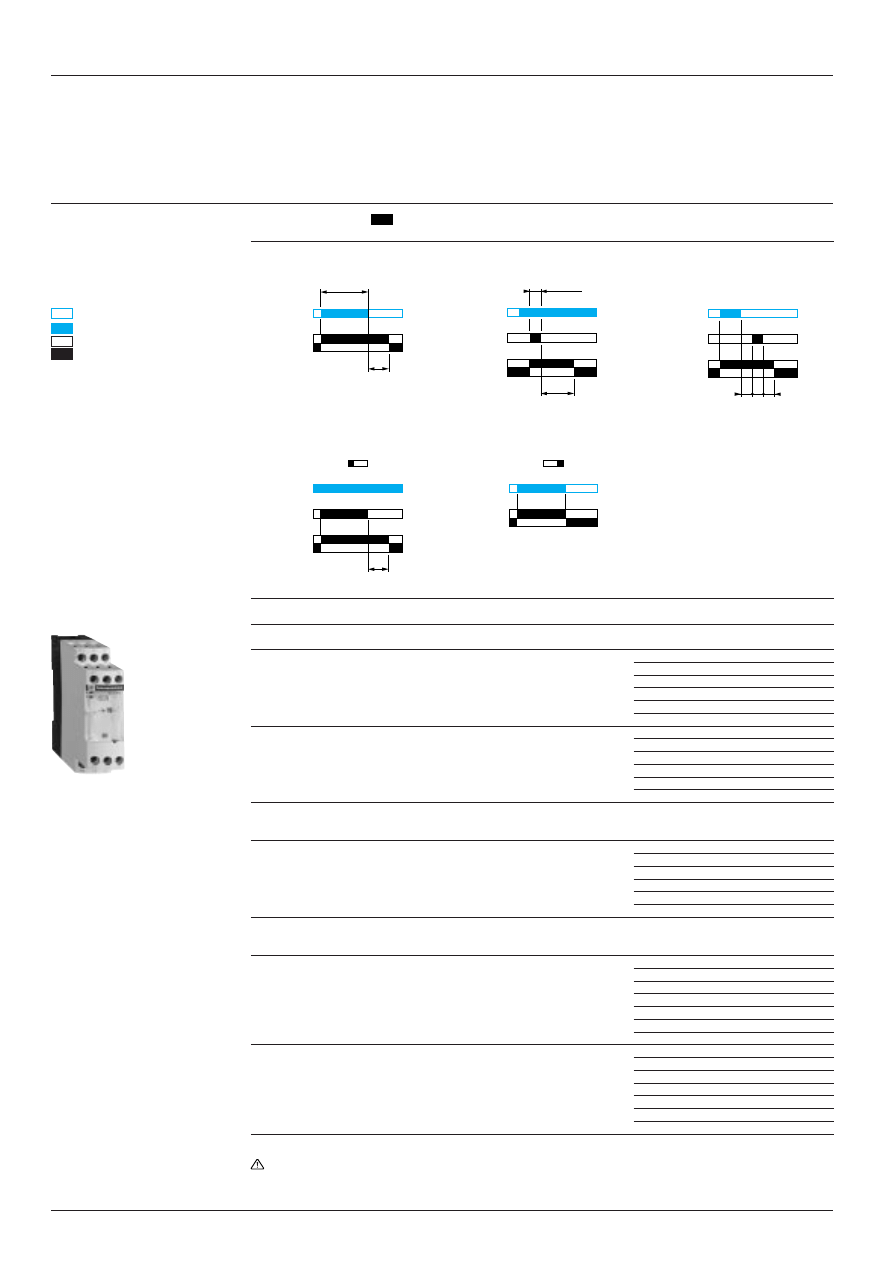
Sequential diagrams
RE1-LA On-delay
Mains supply R must be switched on. When switch K
closes, the set timing period t starts and built-in indicator V
lights up simultaneously. When the set time period t has
elapsed, load C is energised and indicator V goes out. Load
C remains energised until switch K opens or until the mains
supply R is switched off.
RE1-LC Off-delay
Mains supply R must be switched on. When switch K
closes, load C is energised. When switch K opens, timing
starts and built-in indicator V lights up simultaneously.
When set time t has elapsed, load C is de-energised and
indicator V goes out. Load C then remains de-energised
until switch K closes again.
84
=
=
45
=
=
17,5
38
15
(1)
84
=
=
40
=
=
17,5
38
15
60
2xØ4
Characteristics :
page 28411/2
References :
page 28411/3
Compatibility :
page 28411/5
t
0
1
0
1
0
C
V
K
R
1
t
0
1
0
1
0
C
V
K
R
1
Supply
c
Supply
c
or
a
A2
A1
0
t
A1
L
(2)
(1)
K
A2
A1
K
A2
(4)
Y2
(3)
0
t
A1
(1)
L
(2)
28411/5
Te
I0061/2
RE 1 timing relays
Solid state output, width 17.5 mm
Compatibility with other Telemecanique products
The electronic timer can only operate correctly if the characteristics of the equipment with which it is associated are
compatible with the switching characteristics of the timer.
a.c. circuit 50 or 60 Hz
All RE1-LA and RE1-LC electronic timers are compatible with the Telemecanique a.c. controlled components listed
below :
Contactors for electricity supply authority dual tariffs, control relays, plug-in control relays
Type
Operational
Comments
voltage
c
G Y 1 - M
220 V 50 Hz
–
C A 2 - K
24…127 V 50/60 Hz for RE1-LA
on 24 V : use a CA2-KN
iii
Z7
24…240 V 50/60 Hz for RE1-LC
–
C A 2 - D N
24…240 V 50/60 Hz
on 24 V : use a CA2-DN
ii
Z7
C A 2 - D K
24…240 V 50/60 Hz
on 24 V : use a CA2-DK
ii
Z7
RHN, RHK
24…127 V 50/60 Hz
on 24 V : use an RHN, RHK-
iii
JE
Mini-contactors and contactors
L C 1 - K
24…127 V 50/60 Hz for RE1-LA
on 24 V : use an LC1-K
iiii
Z7
24…240 V 50/60 Hz for RE1-LC
–
L C 1 - D 0 9
24…240 V 50/60 Hz
on 24 V : use an LC1-D09
iii
Z7
L C 1 - D 1 2
24…240 V 50/60 Hz
on 24 V : use an LC1-D12
iii
Z7
L C 1 - D 1 8
24…240 V 50/60 Hz
on 24 V : use an LC1-D18
iii
Z7
L C 1 - D 2 5
24…240 V 50/60 Hz
on 24 V : use an LC1-D25
iii
Z7
L C 1 - D 3 2
24…240 V 50/60 Hz
on 24 V : use an LC1-D32
iii
Z7
LC1-D40 to D95
110…240 V 50/60 Hz
–
Integral 18, 32 and 63 contactor breakers
LD1, LD5-LB
110…240 V 50/60 Hz
–
LD1, LD4, LD5-LC and LD
110…240 V 50/60 Hz
–
C o n t a c t o r s
Type
Supply
Coil
Rectifier
voltage
c
LC1-F115, F150, F185, F225, 220, 240 V 50/60 Hz
LX1-FF, FG, FH
iii
2
–
F265, F330
220 V 50/60 Hz
LX9-FJ931
+
DR5-TE4U
240 V 50/60 Hz
LX9-FJ932
+
DR5-TE4U
L C 1 - F 5 0 0
220 V 50/60 Hz
LX9-FK931
+
DR5-TE4U
240 V 50/60 Hz
LX9-FK932
+
DR5-TE4U
L C 1 - F 6 3 0
220 V 50/60 Hz
LX9-FL930
+
DR5-TE4U
240 V 50/60 Hz
LX9-FL931
+
DR5-TE4U
d.c. circuit
RE1-LA timers are compatible with the components listed below :
Mini-control relays, control relays and plug-in control relays
Type
Supply
Comments
voltage
a
C A 3 - K
24…72 V
on 24 V : use a CA3-KN
ii
ZD
C A 3 - D N
24…240 V
on 24 V : use a CA3-DN
ii
ZD
C A 3 - D K
24…240 V
on 24 V : use a CA3-DK
ii
ZD
C A 4 - D N
24 V
Use a CA4-DN
ii
BW
R H N
24…125 V
on 24 V : use an RHN-
iii
JV
R H K
24…125 V
on 24 V : use an RHK-
iii
JV
Mini-contactors and contactors
L P 1 - K
24…72 V
on 24 V : use an LP1-K
iiii
ZD
L P 4 - K
24 V
Use an LP4-K
iiii
BW3
LP1-D09 to D32
24…240 V
on 24 V : use an LP1-D
iiii
ZD
LP1-D40 to D80
48…240 V
–
L P 4 - D 1 2
24 V
Use an LP4-D12
ii
BW
C o n t a c t o r s
Type
Supply
Coil
voltage
a
LC1-F115, F150
220 V
LX4-FF220
240 V
LX4-FF250
LC1-F185, F225
220 V
LX4-FG220
240 V
LX4-FG250
LC1-F265, F330
220 V
LX4-FH220
240 V
LX4-FH250
Other combinations
For other operational voltages and other contactors,
please consult your Regional Sales Office.
R E 1 - L A 0 0 1
R E 1 - L C 1 1 2
R E 1 - L A 3 0 1
Characteristics :
page 28411/2
References :
page 28411/3
Dimensions and schemes :
page 28411/4
28460/2
Te
Alimentation
Etoile
Triangle
Zelio Time timing relays
Functions and selection
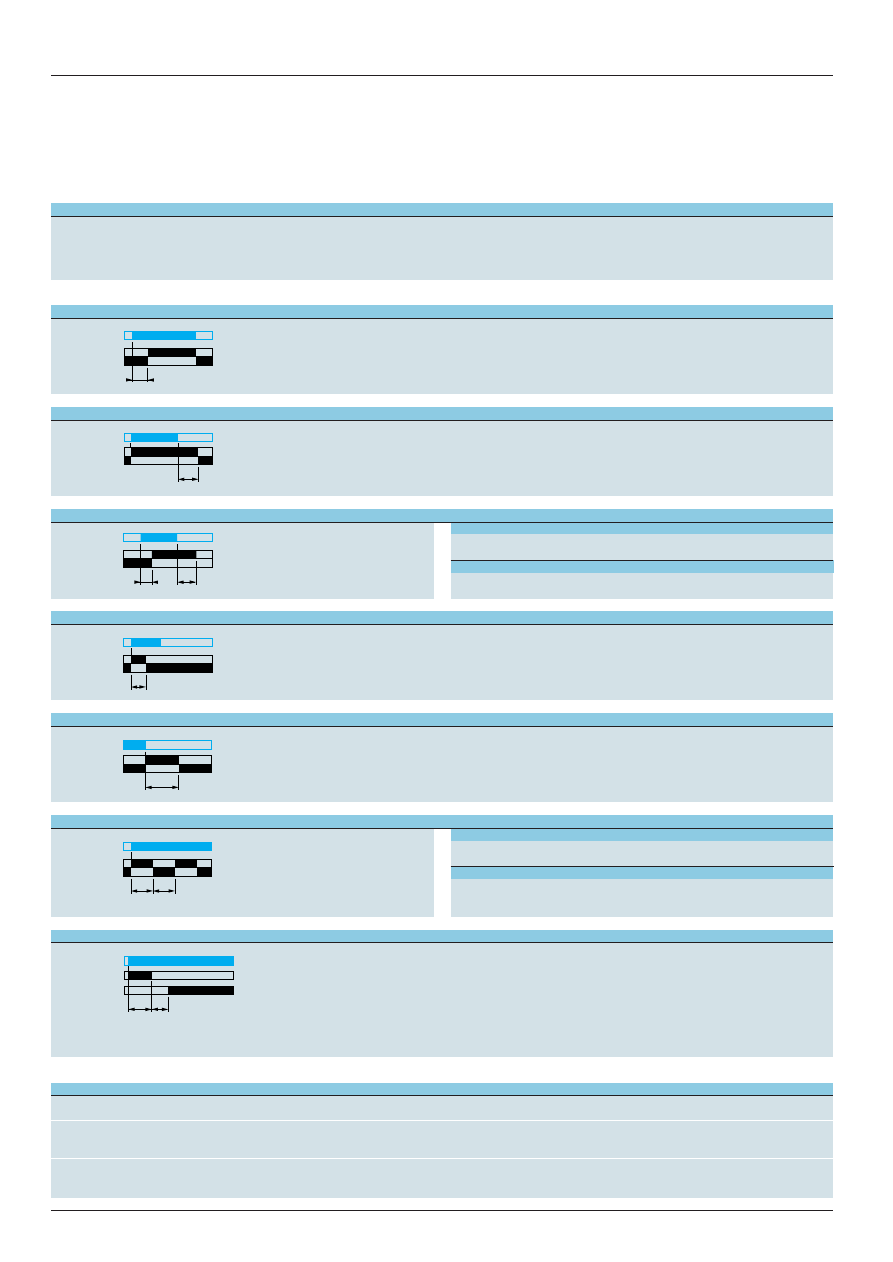
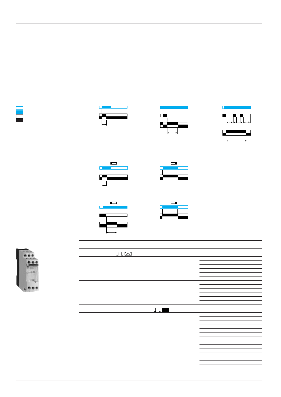
Functions
Diagram
Operating principle
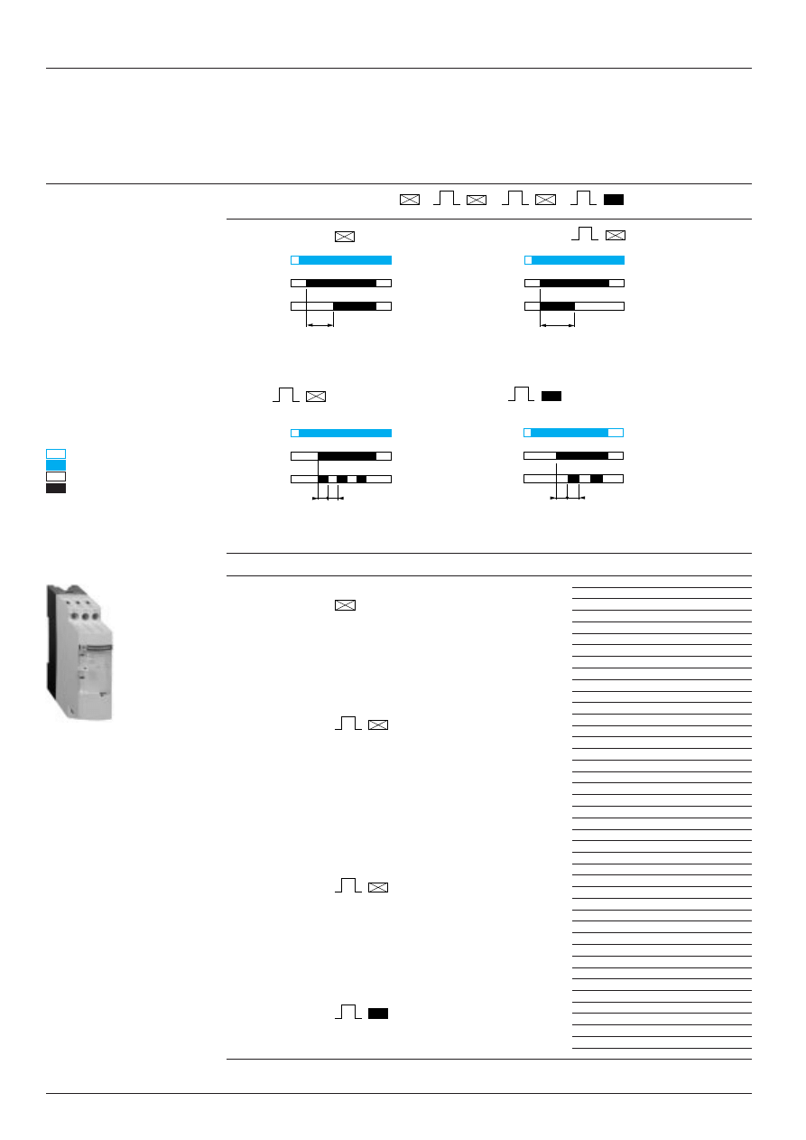
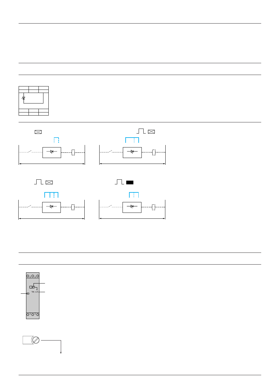
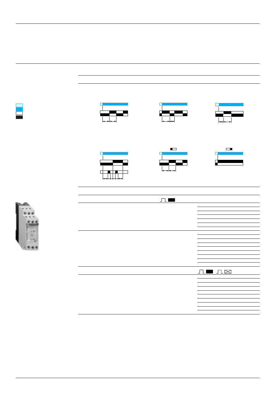
On-delay
Timing starts when the relay is energised. When the set time delay (t) has elapsed, the output contact closes. When the
relay is de-energised, the contact returns to its initial position. The output contact does not close if the duration of the
control instruction is less than the set time delay.
Timing can also be started by opening of a control contact (models with external control).
Off-delay
Energisation of the relay or closing of the control contact (models with external control) causes the output relay to close
instantaneously . Timing starts when the relay is de-energised or when the control contact opens. When the set time delay
(t) has elapsed, the contact returns to its initial position. If the energisation time or closing time of the control contact is
less than the minimum time specified, the timing period does not start.
On and Off-delay
This function is a combination of the
On and Off delay functions. The timing
cycle must be controlled by an external
contact.
Timing relay with pulse on energisation
Energisation of the relay causes the output contact to close instantaneously and start the timing period. The contact
returns to its initial position when the set time delay (t) has elapsed or if the supply is cut off before the end of the timing
period.
Timing relay with pulse on de-energisation or on opening of a external control contact
De-energisation of the relay or opening of the external control contact (depending on model) causes the output contact
to close instantaneously and start the timing period. When the set time delay (t) has elapsed, the contact returns to its
initial position.
Flashing relay
Energisation of the relay starts the
flashing period and causes the output
relay to start the flashing cycle. When
the relay is de-energised, the contact
returns to its initial position.
Time delay relays for star-delta starters
Energisation of the relay causes the star contactor to close instantaneously and starts the timing period. When the set
time delay (t) has elapsed, the star contactor returns to its initial position and the delta contactor closes, after a breaking
time sufficient for the changeover.
Multifunction relays
On-delay - Pulse on energisation contact - Symmetrical flasher
Same functions as above +
Off-delay - Pulse on energisation contact with externally controlled start - Symmetrical flasher
Same functions as above +
Star Delta starting (External control of start of the timing period is not possible for the star delta starting function).
t
t3
ta
tr
t
t
t
t
ta
tr
Control or
supply
C/O contact
Control or
supply
C/O contact
Control or
supply
C/O contact
Supply
C/O contact
Control or
supply
C/O contact
Alimentation
Contact “OF”
Symmetrical
The On and Off delays are equal.
Asymmetrical
The On and Off delays are adjusted by 2 different potentiometers.
Symmetrical flashing relay
The On and Off flashing phases are identical.
Asymmetrical flashing relay
The On and Off flashing phases are adjusted by 2 different potentiometers
(ta and tr).
28460/3
Te
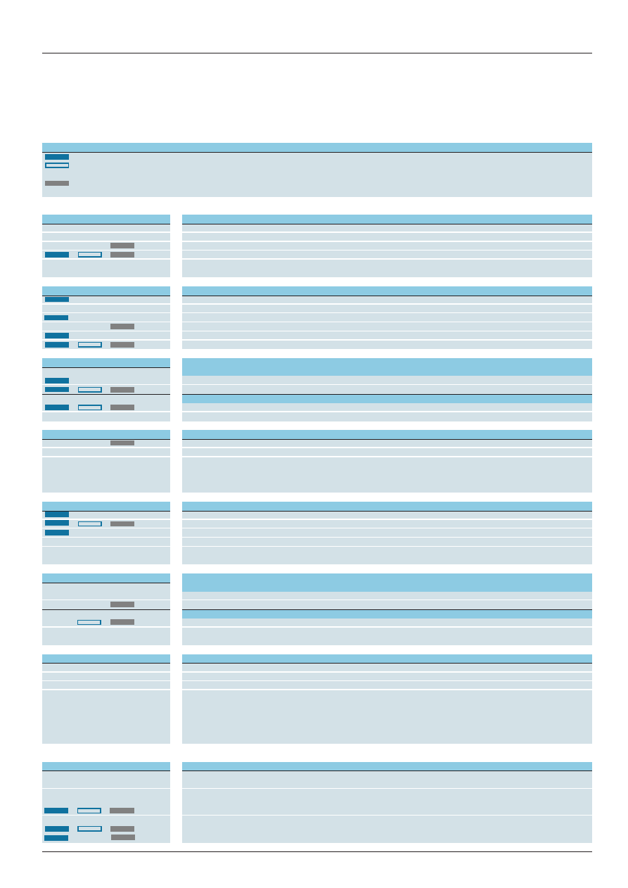
Additional functions
External control of starting: opening of an external contact connected to the relay starts the timing period. Closing of this contact resets the timer.
External control of partial stop of time delay: closing of an external contact connected to the relay allows the timing period to be interrupted. The time
elapsed is memorised. Timing restarts as soon as the contact opens. This type of control enables the totalising function to be performed.
External adjustment of the time delay: one or more external potentiometers can be used for remote adjustment of the timing period or periods.
Output
Multifunction relay
See pages
Solid state
RE9-TA
28466/2
1 C/O
RE7-TL or RE8-TA
RE7: 28451/2, RE8: 28462/2
2 C/O
RE7-TP
28451/2
1 C/O
RE7-TM
28451/2
Solid state
RE9-RA
28466/2
1 C/O
RE7-RB11 or RE8-RB
RE7: 28453/2, RE8: 28462/2
2 C/O
RE7-RL
28453/2
2 C/O
RE7-RB13
28453/2
1 C/O
RE8-RA
28462/2
1 C/O
RE7-RA and RE7-RM
28453/2
2 C/O
RE7-MA13
28452/2
1 C/O
RE7-MA11
28452/2
1 C/O
RE7-MV
28452/2
1 C/O
RE7-PE or RE8-PE
RE7: 28454/2, RE8: 28463/2
2 C/O
RE7-PP
28454/2
1 C/O
RE8-PT
28463/2
2 C/O
RE7-PD
28454/2
1 C/O
RE7-PM
28454/2
1 C/O
RE8-PD
28463/2
1 C/O
RE7-CL or RE8-CL
RE7: 28455/2, RE8: 28462/2
2 C/O
RE7-CP
28455/2
1 C/O
RE7-CV
28455/2
1 C/O
RE8-YG
28463/2
2 C/O
RE7-YA and RE7-YR
28456/2
1 N/C + N/O
RE8-YA
28463/2
Output
Multifunction relay
See pages
Solid state
RE9-MS
28467/2
1 C/O
RE7-ML
28457/2
2 C/O
RE7-MY13MW
28457/2
2 C/O
RE7-MY13BU
28457/2
Te
2 8 4 6 5 / 2
Zelio Time timing relays
Solid state output, width 22.5 mm, optimum
General characteristics
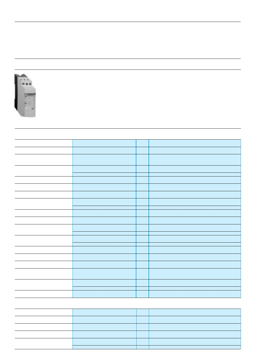
Presentation
The RE9 range of relays is designed for simple, repetitive applications with short and intensive cycles because their solid
state output provides very high electrical durability.
Each product has a single timing range.
Each relay has a wide voltage range from 24 to 240 V.
The range comprises 9 references with 3 model types:
- RE9-TA: On-delay,
- RE9-RA: Off-delay,
- RE9-MS: multifunction.
These products have a transparent, hinged flap on their front face to avoid any accidental alteration of the setting.
This flap can be directly sealed.
Environment
Conforming to standards
IEC 61812-1, EN 61812-1
Product approvals
CSA, GL pending, UL
è
marking
Zelio Time timing relays conform to European regulations
relating to
è
marking
Ambient air temperature
Storage
°
C
- 40…+ 85
around the device
Operation
°
C
- 20…+ 60
Permissible relative humidity range
Conforming to IEC 60721-3-3
15…85 % Environmental class 3K3
Vibration resistance
Conforming to IEC 6068-2-6, 10 to 55 Hz
a = 0.35 ms
Shock resistance
Conforming to IEC 6068-2-27
15 gn - 11 ms
Degree of protection
Casing
IP 50
Terminals
IP 20
Degree of pollution
Conforming to IEC 60664-1
3
Overvoltage category
Conforming to IEC 60664-1
III
Rated insulation voltage
Conforming to IEC
V
250
Conforming to CSA
V
300
Test voltage for
Dielectric test
kV
2.5
insulation tests
Shock wave
kV
4.8
Voltage limits
Power supply circuit
0.85…1.1 Uc
Frequency limits
Power supply circuit
Hz
50/60
±
5 %
Disconnection value
Power supply circuit
> 0.1 Uc
Mounting position
In relation to normal vertical
Any position
without derating
mounting plane
Connection
Flexible cable without cable end
mm
2
2 x 2.5
Maximum c.s.a.
Flexible cable with cable end
mm
2
2 x 1.5
Tightening torque
N.m
0.6…1.1
Immunity to electromagnetic interference (EMC)
(Application class 2 conforming to EN 61812-1)
Electrostatic discharge
Conforming to IEC 61000-4-2
Level 3 (6 kV contact, 8 kV air)
Electromagnetic fields
Conforming to IEC 61000-4-3
Level 3 (10 V/m)
Fast transients
Conforming to IEC 61000-4-4
Level 3 (2 kV)
Shock waves
Conforming to IEC 61000-4-5
Level 3 (2 kV)
Radiated and
CISPR11
Group 1 class A
conducted emissions
CISPR22
Class A
References :
pages 28466/2 and 28467/2
Dimensions :
page 28468/2
Schemes, setting-up :
pages 28466/3 and 28467/3
Compatibility :
page 28468/3
2 8 4 6 5 / 3
Te
Zelio Time timing relays
Solid state output, width 22.5 mm, optimum
General characteristics
(continued)
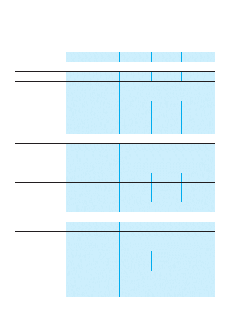
Type of timing relay
RE9-TA
RE9-RA
RE9-MS
On-delay
Off-delay
Multifunction
Power supply characteristics
Supply voltage
V
z
24…240
c
24…240
z
24…240. See page
28467/2
Voltage limits
Power supply circuit
0.85…1.1 Un
Frequency
Hz
50…60
±
5 %
Control contact
Mechanical only
In series
Between Y2 and A2
In series
Maximum length of connecting cable
From contact to RE9
m
–
20
–
Control input consumption
Input Y2
mA
–
5
–
Time delay characteristics
Setting accuracy
<
±
20 %
Repeat accuracy
< 1 %
Minimum reset time
After the time delay period
ms
100
Minimum switching time
ms
–
40
–
Maximum immunity
During the time delay period
ms
100
2
70
to micro-breaks
After the time delay period
ms
2
–
2
Temperature drift
≤
0.1 % per degree centigrade
Switching characteristics
(solid state type)
Maximum continuous current
At ambient temperature: 20
°
C
A
0.7 (minimum 10 mA)
Maximum overload current
VDE 0435 part. 303, 4.8.3/Class II A
15 for 10 ms
Maximum voltage drop
Closed state
V
A 0.7 A : 3
Leakage current
Open state
mA
≤
6
≤
1
≤
6
Maximum dissipated power
W
2.5
4
2.5
Derating
For temperature > 20
°
C
mA
None
Electrical durability
In millions of operating
> 100
cycles
(1) RE9-MS at 60
°
C maximum current: up to 48 V: 400 mA, from 48 V to 240 V: 300 mA.
References :
pages 28466/2 and 28467/2
Dimensions :
page 28468/2
Schemes, setting-up :
pages 28466/3 and 28467/3
Compatibility :
page 28468/3
2 8 4 6 6 / 2
Te
Zelio Time timing relays
Solid state, width 22.5 mm, optimum
Functions, references
On-delay relays
Power supply
Function
Timing
Reference
Weight
circuit
range (1)
kg
a.c.
On-delay
0.1 s…10 s
RE9-TA11MW
0.110
or
d.c.
24…240 V
0.3 s…30 s
RE9-TA31MW
0.110
3 s…300 s
RE9-TA21MW
0.110
40 s…60 min
RE9-TA51MW
0.110
Off-delay relays
Power supply
Function
Timing
Reference
Weight
circuit
range (1)
kg
a.c.
Off-delay
0.1 s…10 s
RE9-RA11MW7
0.110
24…240 V
0.3 s…30 s
RE9-RA31MW7
0.110
3 s…300 s
RE9-RA21MW7
0.110
40 s…60 min
RE9-RA51MW7
0.110
(1) For easier adjustment, it is preferable to set the time delay between the maximum value in the range and one tenth
of this value.
Example: RE9-TA11MW timing range 0.1 s…10 s, recommended use 1 s…10 s.
Characteristics :
pages 28465/2 and 28465/3
Dimensions :
page 28468/2
Schemes, setting-up :
page 28466/3
Compatibility :
page 28468/3
Supply
Control
contact K
Load
Supply
Control
contact K
Load
de-energised
energised
open
closed
t: adjustable On-delay
de-energised
energised
open
closed
t: adjustable Off-delay
t
t
RE9-TA
Te
2 8 4 6 6 / 3
Zelio Time timing relays
Solid state output, width 22.5 mm, optimum
On-delay, Off-delay relays
Schemes, setting-up
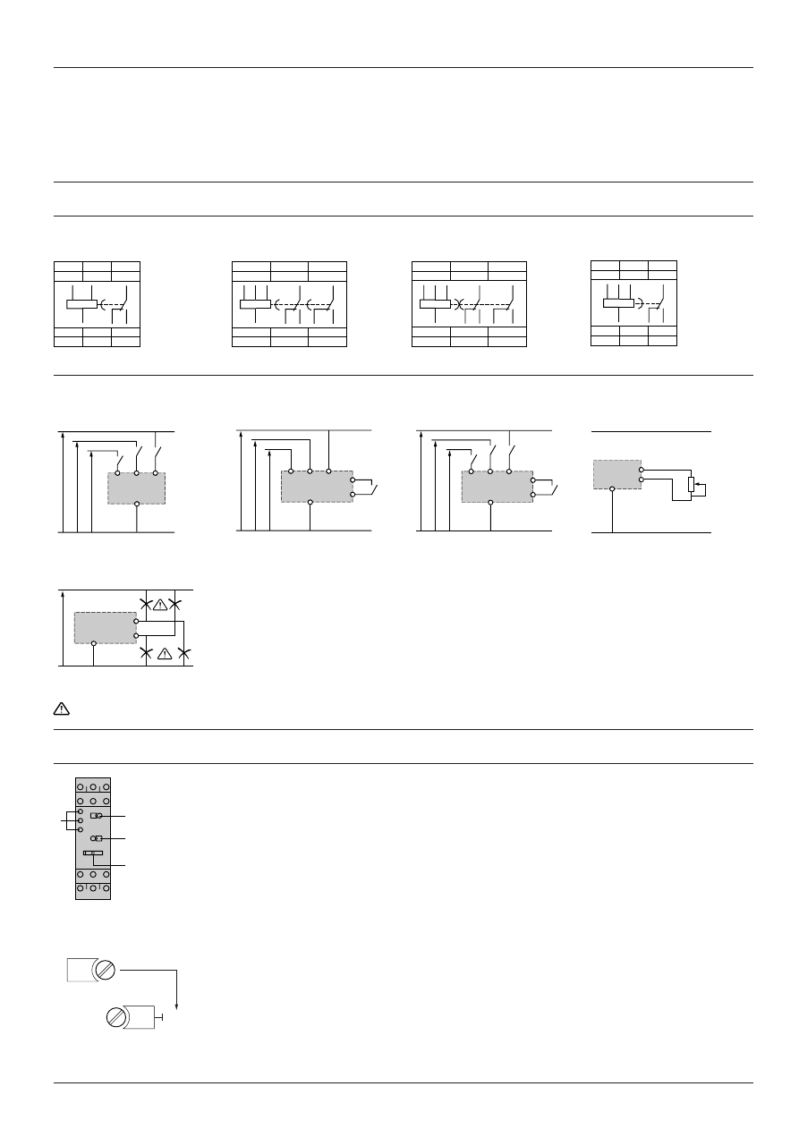
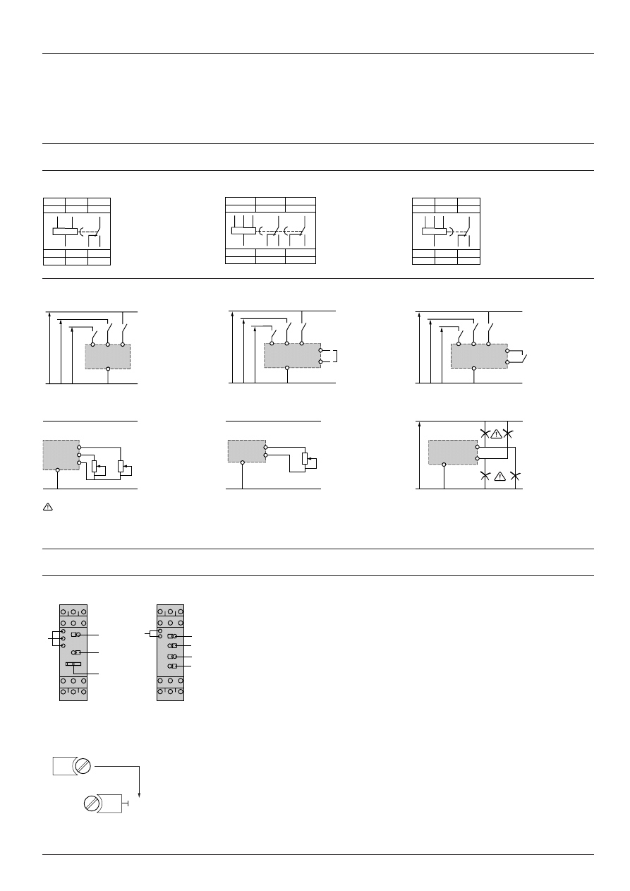
Schemes
Terminal blocks
RE9-TA
RE9-RA
Recommended application schemes
RE9-TA
The timing relay is placed in series with the load whose energisation is to be delayed on one side, and switch
K on the other side. The mains supply may be a.c. or d.c. and the voltage may be between 24 V and 240 V.
See function diagram on page opposite.
RE9-RA
The timing relay is placed in series with the load whose de-energisation is to be delayed. Switch K is
connected to terminals Y2 and A2 of the timing relay, and terminal A2 is connected to the mains supply as
indicated in the scheme opposite. The device is operated from an a.c. mains supply whose voltage is between
24 V and 240 V. See function diagram opposite.
Note: For supply voltages greater than 30 V, the rated voltage of the load is equal to the supply voltage. For a supply voltage of 24 V, the voltage drop within the
RE9 relay must be taken into account (about 3 V); a coil with a nominal voltage of 21 V must therefore be selected for the load (see page 28468/3).
Setting-up
1
Potentiometer for fine adjustment of the time delay, graduated in % of the range
1
, see below.
2
Marking of maximum time delay value.
3
LED :
- Yellow LED: flashes during the time delay period; permanently on outside the time delay period.
Adjustment of the time delay
- The maximum value of the timing range is printed on the product,
2
.
Example: RE9-TA11MW; maximum time delay: 10 s.
- Time required 2.4 s; using potentiometer
1
set the value of the time delay required as a % of value
2
:
t x 100
2.4 x 100
value
1
= –––––– = –––––––– = 24
2
10
Characteristics :
pages 28465/2 and 28465/3
References :
page 28466/2
Dimensions :
page 28468/2
Compatibility :
page 28468/3
L
A1
K
RE9-TA
Supply
c
or
a
L
A1
K
A2
Y2
RE9-RA
Supply
c
3
1
2
24
10 s
x. %
1
2
Time set = 2.4 s
A1
L
A1
L
Y2
A2
Load
Load
2 8 4 6 7 / 2
Te
Zelio Time timing relays
Solid state output, width 22.5 mm, optimum
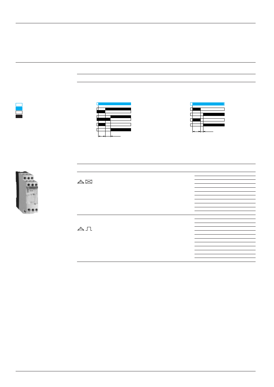
Multifunction timing relays
Functions, references
Multifunction timing relays, , ,
On-delay
Pulse on energisation
Flashing, start
Flashing, start
on energisation of the load
on de-energisation of the load
Power supply
Functions
Timing
Reference
Weight
circuit
range (1)
kg
a.c.
On-delay
3 s…300 s
RE9-MS21MW
0.075
or
and
d.c.
0.1 s…10 s
24…240 V
a.c.
Pulse on energisation
24…240 V
a.c.
Flashing.
24…240 V
Start on
energisation
of the load.
a.c.
Flashing.
24…240 V
Start on
de-energisation
of the load.
(1) For easier adjustment, it is preferable to set the time delay between the maximum value in the range and one tenth
of this value.
Example: RE9-MS21MW timing range 3 s…300 s, recommended use 30 s…300 s.
1
Characteristics :
pages 28465/2 and 28465/3
Dimensions :
page 28468/2
Schemes, setting-up :
page 28467/3
Compatibility :
page 28468/3
Supply
Control
contact K
Load
Supply
Control
contact K
Load
Supply
Control
contact K
Load
Supply
Control
contact K
Load
1
1
RE9-MS
t
t
=
t
=
t
=
t
=
t
de-energised
energised
open
closed
t: time delay
Te
2 8 4 6 7 / 3
Zelio Time timing relays
Solid state output, width 22.5 mm, optimum
Multifunction timing relays
Schemes, setting-up
Schemes
Terminal block
RE9-MS
Recommended application schemes
RE9-MS
On-delay
Pulse on energisation
Selection of timing range
X3-X4 not linked: range 3 s…300 s
(factory configuration)
X3-X4 linked: range 0.1 s…10 s
Link to be made between terminals X1 and X4.
Flashing
Flashing
Start on energisation of the load
Start on de-energisation of the load
Link to be made between terminals X2 and X4
Link to be made between terminals X2 and X4.
on one side and X1 and X2 on the other side.
Note: For supply voltages greater than 30 V, the rated voltage of the load is equal to the supply voltage. For a supply voltage of 24 V, the voltage drop within the
RE9 relay must be taken into account (about 3 V); a coil with a nominal voltage of 21 V must therefore be selected for the load (see page 28468/3).
Setting-up
1
Potentiometer for fine adjustment of the time delay, graduated in % of the range
1
, see below.
2
Marking of maximum time delay value.
3
LED :
- Yellow LED: flashes during the time delay period; permanently on outside the time delay period.
Adjustment of the time delay
- The maximum value of the timing range is printed on the product,
2
.
Example: RE9-MS21MW; maximum time delay: 10 s (X3-X4 linked).
- Time required 2.4 s; using potentiometer
1
set the value of the time delay required as a % of value
2
:
t x 100
2.4 x 100
value
1
= –––––– = –––––––– = 24
2
10
Characteristics :
pages 28465/2 and 28465/3
References :
page 28467/2
Dimensions :
page 28468/2
Compatibility :
page 28468/3
A2
L
A1
A1
K
X3 X4
RE9-MS
Supply
c
or
a
3
1
2
24
10 s
x. %
1
2
time set = 2.4 s
A1
L
X1
X3
X2
X4
1
A2
L
A1
A1
K
X1
X3 X4
RE9-MS
Supply
c
A2
L
A1
A1
K
X2 X3
X1
X4
RE9-MS
Supply
c
A2
L
A1
A1
K
X2 X3 X4
RE9-MS
Supply
c
Load
Load
Load
Load
2 8 4 6 8 / 2
Te
Zelio Time timing relays
Solid state output, width 22.5 mm, optimum
Dimensions, mounting
RE9
Dimensions
Rail mounting
Screw fixing
Characteristics :
pages 28465/2 and 28465/3
References :
pages 28466/2 and 28467/2
Schemes, setting-up:
pages 28466/3 and 28467/3
Compatibility:
page 28468/3
22,5
80
78
89,5
82
Ø 4
6
6
78
Te
2 8 4 6 8 / 3
Zelio Time timing relays
Solid state output, width 22.5 mm, optimum
Compatibility with other Telemecanique products
Correct operation of electronic timing relays is only ensured when the characteristics of the equipment with which they
are associated are compatible with the switching characteristics of the relay.
a.c. circuit, 50 or 60 Hz
RE9-TA, RE9-RA and RE9-MS timing relays are compatible with the products listed below:
Plug-in control relays, control relays
Type
Operational voltage
c
Comments
RHN, RHK
24…110 V 50/60 Hz
On 24 V: use an RHN, RHK
iii
JV
RXN
48…110 V 50/60 Hz for RE9-TA, RA
–
48 V 50/60 Hz for RE9-MS
–
RUN
48…110 V 50/60 Hz
–
CA2-K
24…127 V 50/60 Hz for RE9-TA/MS
On 24 V: use a CA2-K
iii
Z7
24…240 V 50/60 Hz for RE9-RA
On 24 V: use a CA2-K
iii
Z7
CA2-DN/DK
24…240 V 50/60 Hz
On 24 V: use a CA2-DN
iii
Z7
Mini-contactors and contactors
LC1-K
24…127 V 50/60 Hz for RE9-TA, MS
On 24 V: use an LC1-K
iii
Z7
24…240 V 50/60 Hz for RE9-RA
On 24 V: use an LC1-K
iii
Z7
LC1-D09 to D38
24…240 V 50/60 Hz
On 24 V: use an LC1-D09
iii
Z7
LC1-D40 to LC1-D95
110…240 V 50/60 Hz
–
Contactors
Type
Operational voltage
c
Coil
Rectifier
LC1-F115, LC1-F150
220/230 V, 240 V 50/60 Hz
LX1-FF
iii
LC1-F185, LC1-F225
220/230 V, 240 V 50/60 Hz
LX1-FG
iii
LC1-F265, LC1-F330
220/230 V, 240 V 50/60 Hz
LX1-FH
iii
2
LC1-F400, F500, F630
220/230 V 50/60 Hz
LX9-FJ/FK/FL931
+
DR5-TE4U
240 V 50/60 Hz
LX9-FJ/FK/FL932
+
DR5-TE4U
integral 18, 32, 63 contactor breakers
Type
Operational voltage
c
Comments
LD1-LB, LD5-LB
110…240 V 50/60 Hz
–
LD1-LC/LD, LD4-LC/LD.
LD5-LC/LD
110…240 V 50/60 Hz
–
d.c. circuit
RE6-TA and MS timing relays set to on-delay function are compatible with the products listed below:
Plug-in control relays, control relays and mini-control relays
Type
Operational voltage
a
Comments
RE9-TA
RE9-MS
RHN, RHK
24…125 V
24…48 V
On 24 V: use an RHN, RHK
iii
JV
RXN
48 V
–
–
RUN
48 V
48 V
–
CA3-K
24…240 V
24…72 V
On 24 V: use a CA3-K
iii
ZD
CA4-K
24…72 V
24…48 V
On 24 V: use a CA4-K
iii
BW3
CA3-DN/DK
24…240 V
24…240 V
On 24 V: use a CA3-D
iiii
ZD
CA4-DN
24…72 V
24…48 V
On 24 V: use a CA4-DN
iii
BW
Mini-contactors and contactors
LP1-K
24…220 V
24…72 V
On 24 V: use an LP1-K
iii
ZD
LP4-K
24…72 V
24…48 V
–
LP4-D12 to LP4-D25
24…72 V
24…48 V
On 24 V: use an LP4-D
iii
BW
LP1-D09 to LP1-D38
24…240 V
24…240 V
On 24 V: use an LP1-D
iiiii
ZD
LP1-D40 to LP1-D80
48…240 V
48…240 V
–
Contactors
Type
Operational voltage
a
Comments
LC1-F115 to LC1-F330
220/230 V
LX4-FF/FG/FH220
240 V
LX4-FF/FG/FH250
Characteristics :
pages 28465/2 and 28465/3
References :
pages 28466/2 and 28467/2
Dimensions :
page 28468/2
Schemes, setting-up :
pages 28466/3 and 28467/3
Te
2 8 4 5 0 / 2
Zelio Time timing relays
Relay output, width 22.5 mm, universal
General characteristics
Presentation
The RE7 range of relays, with only 23 references, covers all timing applications.
These relays offer multi-range timing from 50 ms to 300 h.
They are multi-voltage.
Three models combine several different functions: multifunction relays.
These products have a transparent, hinged flap on their front face to avoid any
accidental alteration of the settings. This flap can be directly sealed.
Environment
Conforming to standards
IEC 61812-1, EN 61812-1
Product approvals
CSA, GL pending, UL
è
marking
Zelio Time timing relays conform to European
regulations relating to
è
marking
Ambient air temperature
Storage
°
C
- 40…+ 85
around the device
Operation
°
C
- 20…+ 60
Permissible relative humidity range
Conforming to IEC 60721-3-3
15…85 % Environmental class 3K3
Vibration resistance
Conforming to IEC 6068-2-6, 10 to 55 Hz
a = 0.35 ms
Shock resistance
Conforming to IEC 6068-2-27
15 gn - 11 ms
Degree of protection
Casing
IP 50
Terminals
IP 20
Degree of pollution
Conforming to IEC 60664-1
3
Overvoltage category
Conforming to IEC 60664-1
III
Rated insulation voltage
Conforming to IEC
V
250
Between contact circuit and power
supply or between contact circuit
Conforming to CSA
V
300
and control inputs
Test voltage for insulation tests
Dielectric test
kV
2.5
Shock wave
kV
4.8
Voltage limits
Power supply circuit
0.85…1.1 Uc
Frequency limits
Power supply circuit
Hz
50/60
±
5 %
Disconnection value
Power supply circuit
> 0.1 Uc
Mounting position
In relation to normal
Any position
without derating
vertical mounting plane
Connection Maximum c.s.a.
Flexible cable without cable end
mm
2
2 x 2.5
Flexible cable with cable end
mm
2
2 x 1.5
Tightening torque
N.m
0.6…1.1
Immunity to electromagnetic interference (EMC)
(Application class 2 conforming to EN 61812-1)
Electrostatic discharge
Conforming to IEC 61000-4-2
Level 3 (6 kV contact, 8 kV air)
Electromagnetic fields
Conforming to IEC 61000-4-3
Level 3 (10 V/m)
Fast transients
Conforming to IEC 61000-4-4
Level 3 (2 kV)
Shock waves
Conforming to IEC 61000-4-5
Level 3 (2 kV)
Radiated and
CISPR11
Group 1 class A
conducted emissions
CISPR22
Class A
Consumption
c
50/60 Hz
a
Average consumption
24 V
48 V
110 V 240 V
24 V
48 V
110 V 240 V
RE7-
ii
11BU
VA
0.7
1.6
1.8
8.5
W
0.5
1.2
–
–
RE7-
ii
12BU and RE7-
ii
13BU
VA
1.2
2
2.8
12.5
W
0.8
1.6
–
–
RE7-
iiii
MW (1)
VA
2
2.5
3.2
6
W
2
1
3.2
2
(1) RE7-RB
ii
MW: current peak on energisation = 1 A / 30 ms.
References :
pages 28451/2 to 28457/2
Dimensions :
page 28458/2
Schemes :
pages 28451/3 to 28458/2
Setting-up :
pages 28451/3 to 28458/3
2 8 4 5 0 / 3
Te
10
1
0,1
0,01
0
1
2
3
4
5
6
7
8
A
1
0,6
0,5
0,9
0,8
0,7
0,4
0,3
1
0,8
0,6 0,5
0,4
0,3
0,2
300
40
30
200
100
50
20
10
0,1
0,2
0,5
1
2
5
20
10
1
2
3
A
RE7
K
+
–
Zelio Time timing relays
Relay output, width 22.5 mm, universal
General characteristics
(continued)
Time delay characteristics
Setting accuracy
As % of the full scale value
±
10 %
Repeat accuracy
±
0.2 %
Influence of voltage
In the voltage range, 0.85…1.1 Un
< 0.2 %
Influence of temperature
< 0.07 %/
°
C
Immunity to micro-breaks
ms
3
Minimum control pulse
ms
20 (except RE7-RB1
i
MW: 1 s)
Reset time
ms
50
Output circuit characteristics
Maximum switching voltage
V
z
250
Mechanical durability
In millions of operating cycles
20
Current limit Ith
A
8 (except RE7-RB
ii
MW: 5 A)
Rated operational limits at 70
°
C
24 V
115 V
250 V
Conforming to IEC 60947-5-1/1991
AC-15
A
3
3
3
and VDE 0660
DC-13
A
2
0.2
0.1
Minimum switching capacity
12 V/10 mA
Contact material
Nickel Silver 90/10
(except RE7-RB
ii
MU: gold flashed silver alloy)
Remote control input characteristics
Maximum voltage
Applicable to inputs
V
60
Y1Z2, X1Z2, X2Z2
Signal delivered by Y1Z2,
Switching current
mA
< 1
X1Z2, X2Z2 control inputs
Maximum distance
m
50
No galvanic insulation between
Compatibility
3/4-wire PNP and NPN Telemecanique sensors or
these inputs and the supply
other sensors without an internal load
Potentiometer for connection
Type
Linear at
±
20 %
between terminals Z1Z2, Z3Z2
Resistance
k
Ω
47
±
20 %
Power
W
0.2
Maximum distance
m
25 by shielded cable: shielding linked to terminal Z2
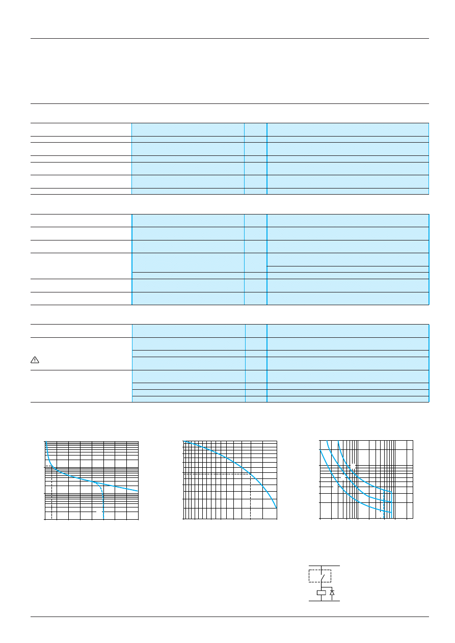
a.c. load
d.c. load
Curve 1
Curve 2
Load limit curve
Electrical durability of contacts on resistive
Reduction factor k for inductive loads
load in millions of operating cycles
(applies to values taken from the
durability curve opposite)
A
RE7-RB
ii
MW
A
RE7-RB
ii
MW
1
L/R = 20 ms
Example:
2
L/R with load protection diode
3
Resistive load
An LC1-F185 contactor supplied with 115 V/50 Hz for a consumption of 55 VA or a current
consumption equal to 0.1 A and cos
ϕ
= 0.3
For 0.1 A, curve 1 indicates a durability of approximately 1.5 million operating cycles.
As the load is inductive, it is necessary to apply a reduction coefficient k to this number of
cycles, as indicated by curve 2.
For cos
ϕ
= 0.3: k = 0.6
The electrical durability therefore becomes:
1.5 10
6
operating cycles x 0.6 = 900 000 operating cycles
Millions of operating cycles
Current broken in A
Power factor on breaking (cos
ϕ
)
Reduction factor k
Current in A
References :
pages 28451/2 to 28457/2
Dimensions :
page 28458/2
Schemes :
pages 28451/3 to 28458/2
Setting-up :
pages 28451/3 to 28458/3
Voltage in V
28451/2
Te
Zelio Time timing relays
Relay output, width 22.5 mm, universal
On-delay relays
Functions, references
On-delay relays
Time delay adjustable from 0.05 s to 300 h in 10 ranges (see setting-up procedure on page opposite).
On-delay relay
External control for
External control for partial
Start on
start of time delay
stop of time delay
energisation
RE7-TM
(for totalising function)
RE7-TL, TM, TP
RE7-TM
Conversion of second changeover contact to instantaneous mode by means of switch R2
RE7-TP13BU
Functions (see
Supply
Relay
Reference
Weight
diagrams above)
voltages
output
kg
On-delay relay
a
or
c
24 V
1 C/O
RE7-TL11BU
0.150
c
110…240 V
On-delay relay
a
or
c
24 V
1 C/O
RE7-TM11BU
0.150
External control possible for:
a
or
c
42…48 V
- start of time delay
c
110…240 V
- partial stop of time delay
- adjustment of time delay (1)
On-delay relay
a
or
c
24 V
2 C/O
(2)
RE7-TP13BU
0.150
Remote control possible for:
a
or
c
42…48 V
- adjustment of time delay (1)
c
110…240 V
(1) By external potentiometer, to be ordered separately. If external potentiometer is fitted, the internal potentiometer is
automatically disconnected.
(2) A switch on the front face of the relay allows the second changeover contact to be used in instantaneous mode.
de-energised
energised
open
closed
t: adjustable On-delay
Supply
C/O
Supply
Start
C/O
Supply
Partial stop
Supply
C/O
Supply
C/O
C/O
Delay Inst
Delay Inst
15/18 (25/28)
15/16 (25/26)
t
15/18
15/16
(Y1Z2)
t
15/18
15/16
(X1Z2)
t
t
=
t1
+
t2
+
t3
t3
t2
t1
R2
R2
21/24
25/28
t
21/22
25/26
RE7- T
Te
28451/3
A1
15
B1
18
16
A2
18
15
B1
A1
A2
16
Zelio Time timing relays
Relay output, width 22.5 mm, universal
On-delay relays
Schemes, setting-up
Schemes
Terminal blocks
RE7-TL11BU
RE7-TP13BU
RE7-TM11BU
Recommended application schemes
Start on energisation
Start by external contact
External control of partial stop
Potentiometer wiring
Wiring precautions
No galvanic insulation between supply terminals A1, A2, B1, B2 and control inputs X1, Y1, Z1, Z2.
Setting-up
1
Potentiometer for fine adjustment of the time delay, graduated in % of range max. setting
2
.
2
10-position timing range selector:
0.05…1 s
0.5…10 s
5…100 s
1.5…30 min
1.5…30 h
0.15…3 s
1.5…30 s
15…300 s
15…300 min
15…300 h
3
Switch for converting the second C/O contact to instantaneous mode (for RE7-TP13BU).
4
LEDs, depending on the model:
- Green LED U/T: flashes during the time delay period, permanently on outside the time delay period.
- Yellow LED R1: on when the 1
st
relay is energised.
- Yellow LED R2: on when the 2
nd
relay is energised.
Adjustment of the time delay
- Select the timing range immediately greater than the time required, using selector switch
2
.
Example: time required 12 s; range selected 30 s.
- Using potentiometer
1
display the required time value as a % of value
2
.
t x 100
12 x 100
1
= ––––––
i.e.
––––––– = 40
2
30
A1
15
B1
Z1
B2
Y1
X1
Z2
18
16
A2
18
15
B1
A1
B2
A2
16
z
24 V
z
42 … 48 V
c
110 … 240 V
B1
A1
B2
A2
4
1
2
3
A1
15
B1
25 (21)
Z1
B2
28 (24)
Z2
18
26 (22)
16
A2
18
15
B1
A1
B2
A2
16
28
25
(21)
26
(24)
(22)
40
30 s
x. %
1
2
B1
A1
B2
A2
Y1
Z2
z
24 V
z
42…48 V
c
110 … 240 V
B1
A1
B2
A2
X1
Z2
z
24 V
z
42…48 V
c
110 … 240 V
Z1
Z2
A2
A2
Z2
X1 or Y1 or Z1
Supply
2 8 4 5 2 / 2
Te
RE7-M
Zelio Time timing relays
Relay output, width 22.5 mm, universal
On-delay and Off-delay relays
Functions, references
On-delay and Off-delay relays ,
Time delay adjustable from 0.05 s to 300 h in 10 ranges (see setting-up procedure on page opposite).
External control for
Remote control for partial stop of time delay
start of time delay
RE7-MA11BU and MV11BU
RE7-MA and MV
Conversion of second changeover contact to instantaneous mode by means of switch R2
RE7-MA13BU
Functions
Supply
Relay
Reference
Weight
(see diagrams above)
voltages
output
kg
Symmetrical relays: On and Off delay times are equal.
On-delay and Off-delay relay
a
or
c
24 V
1 C/O
RE7-MA11BU
0.150
External control possible for
a
or
c
42…48 V
- partial stop of time delay
c
110…240 V
- adjustment of time delay (1)
Start control via
external contact only
On-delay and Off-delay relay
a
or
c
24 V
2 C/O (2)
RE7-MA13BU
0.150
Start control via
a
or
c
42…48 V
external contact only
c
110…240 V
Asymmetrical relays: On and Off delay times are adjusted separately.
On-delay and Off-delay relay
a
or
c
24 V
1 C/O
RE7-MV11BU
0.150
External control possible for
a
or
c
42…48 V
- partial stop of time delay
c
110…240 V
- adjustment of time delays (1)
Start control via
external contact only
(1) By external potentiometer(s), to be ordered separately. If external potentiometer(s) is/are fitted, the internal
potentiometer(s) is/are automatically disconnected.
(2) A switch on the front face of the relay allows the second changeover contact to be used in instantaneous mode.
Supply
Start
C/O
Start
C/O
Partial stop
of time delay
Supply
Start
C/O
Supply
C/O
de-energised
energised
open
closed
ta : adjustable On-delay
tr: adjustable Off-delay
ta = t1 + t2
tr = t3 + t4
ts: partial stop time
Characteristics :
pages 28450/2 and 28450/3
Dimensions :
page 28458/2
Schemes :
page 28458/2
Setting-up :
page 28458/3
15/18 (25/28)
Y1Z2
15/16 (25/26)
tr
ta
15/18
15/16
X1Z2
Y1Z2
t2
t1
ts
t4
t3
ts
ta
tr
R2
R2
25/28
25/26
21/24
21/22
Delay Inst
Delay Inst
Te
2 8 4 5 2 / 3
A1
15
B1
Z1
Z3
B2
Y1
X1
Z2
18
16
A2
18
15
B1
A1
B2
A2
16
A1
15
B1
Z1
B2
Y1
X1
Z2
18
16
A2
18
15
B1
A1
B2
A2
16
B1
A1
B2
A2
X1
Z2
z
24 V
z
42…48 V
c
110 … 240 V
B1
A1
B2
A2
Y1
Z2
z
24 V
z
42…48 V
c
110 … 240 V
Zelio Time timing relays
Relay output, width 22.5 mm, universal
On-delay and Off-delay relays
Schemes, setting-up
Schemes
Terminal blocks
RE7-MA13BU
RE7-MA11BU
RE7-MV11BU
Recommended application schemes (for other schemes, see page 28458/2)
Start by external control
External control of partial stop
Potentiometer wiring
Potentiometer wiring
Wiring precautions
for symmetrical relay
for asymmetrical relays
RE7-MA
RE7-MV11BU
No galvanic insulation between supply terminals A1, A2, B1, B2 and control inputs X1, Y1, Z1, Z2.
(1) On-delay adjustment
(2) Off-delay adjustment
Setting-up procedure
Symmetrical
Asymmetrical
timing relay
timing relay
1
Potentiometer for fine adjustment of the time delay, graduated in % of range max. setting
2
2
10-position timing range selector :
0.05…1 s
0.5…10 s
5…100 s
1.5…30 min
1.5…30 h
0.15…3 s
1.5…30 s
15…300 s
15…300 min
15…300 h
A
On-delay adjustment (ta).
B
Off-delay adjustment (tr).
3
Switch for converting the second changeover contct to instantaneous mode (RE7-MA13BU).
4
LEDs, depending on the model :
- Green LED: flashes during the time delay period, permanently on outside the time delay period
- Yellow LED 1: on when the 1
st
relay is energised
- Yellow LED 2: on when the 2
nd
relay is energised
Adjustment of the time delay
- Select the timing range value immediately greater than the time required using selector switch
2
.
Example: required time 12 s; range selected 30 s.
- Using potentiometer
1
display the required time as a % of value
2
.
t x 100
12 x 100
1
= ––––––
i.e.
––––––– = 40
2
30
Characteristics :
pages 28450/2 and 28450/3
References :
page 28452/2
Dimensions :
page 28458/2
Z1
Z3
(1)
(2)
Z2
A2
4
1
]
A
2
1
]
B
2
4
1
2
3
Z1
Z2
A2
A1
15
B1
25 (21)
Y1
B2
26 (22)
28 (24)
Z2
18
16
A2
18
15
B1
A1
B2
A2
16
28
25
26
(24)
(21)
(22)
40
30 s
x. %
1
2
A2
Z2
Supply
X1 or Y1 or Z1
28453/2
Te
Zelio Time timing relays
Relay output, width 22.5 mm, universal
Off-delay relays
Functions, references
Off-delay relays
Off-delay relays
External control for
Remote control for
RE7-RB
start of time delay
partial stop of time delay
RE7-RA, RM
RE7-RA, RM
Conversion of second changeover contact to instantaneous mode by means of switch R2
RE7-RL13BU
Functions
Supply
Relay
Reference
Weight
(see diagrams above)
voltages
output
kg
On de-energisation, adjustable from 0.05 s to 10 min in 7 ranges (see setting-up procedure on page opposite).
Off-delay relay
a
or
c
24…240 V
1 C/O
RE7-RB11MW (1)
0.150
Off-delay relay
a
or
c
24…240 V
2 C/O
RE7-RB13MW (1)
0.150
Remote control possible for:
- adjustment of time delay (2)
On opening of external control contact, adjustable from 0.05 s to 300 h in 10 ranges (see setting-up procedure on
page opposite).
Off-delay relay
a
or
c
24 V
1 C/O
RE7-RA11BU
0.150
External control possible for:
a
or
c
42…48 V
- partial stop of time delay
c
110…240 V
- adjustment of time delay (2)
On opening of low level external control contact, adjustable from 0.05 s to 300 h in 10 ranges (see setting-up
procedure on page opposite).
Off-delay relay
a
or
c
24 V
1 C/O
RE7-RM11BU
0.150
External control possible for:
a
or
c
42…48 V
- partial stop of time delay
c
110…240 V
- adjustment of time delay (2)
Off-delay relay
a
or
c
24 V
2 C/O (3)
RE7-RL13BU
0.150
a
or
c
42…48 V
c
110…240 V
(1) If the device has been stored, de-energised, for more than a month, it must be energised for about 15 seconds to
activate it. Subsequently, a time of > 1 s is enough to activate the time delay.
If this time is not complied with, the relay will remain energised indefinitely.
(2) By external potentiometer, to be ordered separately. If external potentiometer is fitted, the internal potentiometer is
automatically disconnected.
(3) A switch on the front face of the relay allows the second changeover contact to be used in instantaneous mode.
de-energised
energised
open
closed
t: adjustable Off-delay
t = t1 + t2
t : partial stop time
RE7-R
Supply
C/O
Supply
Start
C/O
Start
Partial stop
C/O
Supply
Start
C/O
Supply
C/O
15/18 (25/28)
15/16 (25/26)
t
> 1 s
(1)
15/18
15/16
t
> 20 ms
15/18
X1Z2
Y1Z2
15/16
ts
t1
t2
R2
R2
tr
25/28
25/26
21/24
21/22
Delay Inst
Delay Inst
28453/3
Te
Zelio Time timing relays
Relay output, width 22.5 mm, universal
Off-delay relays
Schemes, setting-up
Schemes
Terminal blocks
RE7-RL13BU
RE7-RB11MW
RE7-RB13MW
RE7-RM11BU and RE7-RA11BU
Recommended application schemes
Start on de-energisation
Start by low level
Remote control
Potentiometer wiring
external control
of partial stop
RE7-RB
RE7-RM and RL
RE7-RA and RM
Start by external control
Wiring precautions
RE7-RA
RE7-RM and RL
No galvanic insulation between supply terminals A1, A2, B1, B2 and control inputs X1, Y1, Z1, Z2.
Setting-up procedure
1
Potentiometer for fine adjustment of the time delay, graduated in % of range max. setting
2
.
2
Timing range selector:
- 10-position (RE7-RA, RM, RL)
0.05…1 s
0.5…10 s
5…100 s
1.5…30 min
1.5…30 h
0.15…3.s
1.5…30 s
15…300 s
15…300 min 15…300 h
- 7-position (RE7-RB)
0.05…1 s
0.5…10 s
5…100 s
1.5…10 min
0.15…3.s
1.5…30 s
15…300 s
3
Switch for converting the second changeover contact to instantaneous mode (RE7-RL13BU).
4
LEDs, depending on the model:
- Green LED U/T: flashes during the time delay period, permanently on outside the time delay period.
- Yellow LED R1: on when 1
st
relay is energised.
- Yellow LED R2: on when 2
nd
relay is energised.
- RE7-RB
ii
MW: the green LED does not flash during the time delay period and there is only one yellow
LED (R).
Adjustment of the time delay
- Select the timing range immediately greater than the time required, using selector switch
2
.
Example: required time 12 s; range selected 30 s.
- Using potentiometer
1
display the required time value as a % of value
2
.
t x 100
12 x 100
1
= ––––––
i.e.
––––––– = 40
2
30
A1
15
B1
25 (21)
Y1
B2
26 (22)
28 (24)
Z2
18
16
A2
18
15
B1
A1
B2
A2
16
28
25
26
(24)
(21)
(22)
A1
15
18
16
A2
18
15
A1
A2
16
A1
15
25
Z1
26
Z2
28
18
16
A2
18
15
A1
A2
16
28
25
26
A1
15
B1
Z1
B2
Y1
X1
Z2
18
16
A2
18
15
B1
A1
B2
A2
16
B1
A1
B2
A2
Y1
Z2
z
24 V
z
42…48 V
c
110 … 240 V
z
24 … 240 V
A1
A2
A1
A2
Y1
c
110 … 240 V
B1
A1
B2
A2
X1
Z2
z
24 V
z
42…48 V
c
110 … 240 V
Z1
Z2
A2
B1
A2
Y1
c
24 V
a
24 V
+
–
B2
A2
Y1
c
42…48 V
a
42…48 V
+
–
40
30 s
x. %
1
2
4
1
2
3
A2
Z2
Supply
2 8 4 5 4 / 2
Te
Zelio Time timing relays
Relay output, width 22.5 mm, universal
Pulse on energisation relays
Functions, references
Pulse on energisation relays
Time delay adjustable from 0.05 s to 300 h in 10 ranges (see setting-up procedure on page opposite)
Pulse on energisation relay
Start on opening of
External control for
Start on energisation
external control contact
partial stop of time delay
RE7-PE, PP
RE7-PM, PD
(for totalising function)
RE7-PM
Conversion of second changeover contact to instantaneous mode by means of switch R2
RE7-PP
RE7-PD
Functions
Supply
Relay
Reference
Weight
(see diagrams above)
voltages
output
kg
Start on energisation
Pulse on energisation relay
a
or
c
24 V
1 C/O
RE7-PE11BU
0.150
c
110…240 V
Pulse on energisation relay
a
or
c
24 V
2 C/O (1)
RE7-PP13BU
0.150
External control possible for
a
or
c
42…48 V
- adjustment of time delay (2)
c
110 …240 V
Start on opening of external control contact
Pulse on energisation relay
a
or
c
24 V
1 C/O
RE7-PM11BU
0.150
External control possible for
a
or
c
42…48 V
- partial stop of time delay
c
110…240 V
- adjustment of time delay (2)
Pulse on energisation relays
a
or
c
24 V
2 C/O (1)
RE7-PD13BU
0.150
a
or
c
42…48 V
c
110…240 V
(1) A switch on the front face of the relay allows the second changeover contact to be used in instantaneous mode.
(2) By external potentiometer, to be ordered separately. If external potentiometer is fitted, the internal potentiometer is
automatically disconnected.
1
1
Characteristics :
pages 28450/2 and 28450/3
Dimensions :
page 28458/2
Schemes :
page 28458/2
Setting-up :
page 28458/3
RE7-P
Supply
C/O
Supply
Start
C/O
Supply
Partial stop
C/O
Supply
C/O
Supply
C/O
15/18
X1Z2
15/16
t
t
=
t1
+
t2
+
t3
t1
t2
t3
15/18
Y1Z2
15/16
t
R2
R2
25/28
25/26
t
21/24
21/22
15/18 (25/28)
15/16 (25/26)
t
R2
R2
21/24
21/22
25/28
Y1Z2
25/26
t
Supply
Start
C/O
Supply
C/O
Delay Inst
Delay Inst
Delay Inst
Delay Inst
de-energised
energised
open
closed
t: pulse time
ts: partial stop time
2 8 4 5 4 / 3
Te
1
2
3
4
Zelio Time timing relays
Relay output, width 22.5 mm, universal
Pulse on energisation relays
Schemes, setting-up
Schemes
Terminal blocks
RE7-PE11BU
RE7-PP13BU
RE7-PD13BU
RE7-PM11BU
Recommended application schemes (for other schemes, see page 28458/2)
Start on energisation
Start by external contact
External control of partial stop
Potentiometer wiring
RE7-PE, PP
RE7-PM, PD
Wiring precautions
No galvanic insulation between supply terminals A1, A2, B1, B2 and control inputs X1, Y1, Z1, Z2.
(1)
a
or
c
42…48 V: RE7-PP.
Setting-up procedure
1
Potentiometer for fine adjustment of the time delay, graduated in % of range max. setting
2
.
2
10-position timing range selector :
0.05…1 s
0.5…10 s
5…100 s
1.5…30 min
1.5…30 h
0.15…3 s
1.5…30 s
15…300 s
15…300 min
15…300 h
3
Switch for converting the second changeover contact to instantaneous mode (RE7-PP13BU and PD13BU).
4
LEDs, depending on the model:
- Green LED: flashes during the time delay period (except for the first 2 timing ranges), permanently on
outside the time delay period
- Yellow LED 1: on when 1
st
relay is energised
- Yellow LED 2: on when 2
nd
relay is energised
Adjustment of the time delay
- Select the timing range immediately greater than the time required using selector switch
2
.
Example: required time 12 s; range selected 30 s.
- Using potentiometer
1
display the required time as a % of value
2
.
t x 100
12 x 100
1
= ––––––
i.e.
––––––– = 40
2
30
Characteristics :
pages 28450/2 and 28450/3
References :
page 28454/2
Dimensions :
page 28458/2
A1
15
B1
18
16
A2
18
15
B1
A1
A2
16
A1
15
B1
25 (21)
Z1
B2
26 (22)
28 (24)
Z2
18
16
A2
18
15
B1
A1
B2
A2
16
28
25
26
(24)
(21)
(22)
A1
15
B1
25 (21)
Y1
B2
26 (22)
28 (24)
Z2
18
16
A2
18
15
B1
A1
B2
A2
16
28
25
26
(24)
(21)
(22)
B1
A1
B2
A2
X1
Z2
z
24 V
z
42…48 V
c
110 … 240 V
B1
A1
B2
A2
Y1
Z2
z
24 V
z
42…48 V
c
110 … 240 V
z
24 V
(1)
c
110 … 240 V
B1
A1
B2
A2
A1
15
B1
Z1
B2
Y1
X1
Z2
18
16
A2
18
15
B1
A1
B2
A2
16
Z1
Z2
A2
A2
Z2
Supply
X1 or Y1 or Z1
40
30 s
x. %
1
2
2 8 4 5 5 / 2
Te
Zelio Time timing relays
Relay output, width 22.5 mm, universal
Flashing relays
Functions, references
Flashing relays
Time delay adjustable from 0.05 s to 300 h in 10 ranges (see setting-up procedure on page opposite).
Symmetrical flashing relay
Asymmetrical flashing relay
RE7-CL, CP
Start during the ON period
Start during the OFF period
RE7-CV (X2Z2 linked)
RE7-CV (X2Z2 not linked)
External control for
Conversion of second changeover contact
partial stop of time delay
to instantaneous mode by means of switch R2
RE7-CV
RE7-CP
Functions
Supply
Relay
Reference
Weight
(see diagrams above)
voltages
output
kg
Symmetrical relays with start during OFF period
Flashing relay
a
or
c
24 V
1 C/O
RE7-CL11BU
0.150
c
110 … 240 V
Flashing relay
a
or
c
24 V
2 C/O (1)
RE7-CP13BU
0.150
External control possible for
a
or
c
42…48 V
- adjustment of time delay (2)
c
110…240 V
Asymmetrical relay with separate adjustment of On-delay and Off-delay
Flashing relay
a
or
c
24 V
1 C/O
RE7-CV11BU
0.150
External control possible for
a
or
c
42…48 V
- start period
c
110…240 V
- adjustment of time delays (2)
- partial stop
(1) A switch on the front face of the relay allows the second changeover contact to be used in instantaneous mode.
(2) By external potentiometers, to be ordered separately. If external potentiometers are fitted, the internal potentiometers
are automatically disconnected.
RE7-C
Characteristics :
pages 28450/2 and 28450/3
Dimensions :
page 28458/2
Schemes :
page 28458/2
Setting-up :
page 28458/3
de-energised
energised
open
closed
t, t1 and t2 : adjustable time delays
ts: partial stop time
t : flashing time
ta: On-delay period
tr: Off-delay period
ta = t1 + t2
tr = t3 + t4
Supply
C/O
Supply
C/O
Supply
C/O
R2
R2
25/28
25/26
t
t
21/24
21/22
Supply
C/O
Partial stop
Supply
C/O
15/18 (25/28)
X1Z2
15/16 (25/26)
t1
t3
t4
t2
ts
ts
Supply
C/O
15/18 (25/28)
15/16 (25/26)
t
t
15/18 (25/28)
15/16 (25/26)
ta
tr
ta
tr
Delay Inst
Delay Inst
2 8 4 5 5 / 3
Te
Zelio Time timing relays
Relay output, width 22.5 mm, universal
Flashing relays
Schemes, setting-up
Schemes
Terminal blocks
RE7-CL11BU
RE7-CP13BU
RE7-CV11BU
Recommended application schemes (for other schemes: see page 28458/2)
Start on energisation
Start period selection
External control of partial stop
RE7-CV
RE7-CV
Potentiometer wiring
Potentiometer wiring
Wiring precautions
RE7-CV
RE7-CP
No galvanic insulation between supply terminals A1, A2, B1, B2 and control inputs X1, Y1, Z1, Z2.
(1)
a
or
c
42…48 V: RE7-CP13BU and RE7-CV11BU.
(2) Start during ON period: X2Z2 connected. Start during OFF period: X2-Z2 not linked.
(3) Off-delay adjustment (tr) (contact 15/16 closed).
(4) On-delay adjustment (ta) (contact 15/18 closed).
Setting-up procedure
Symmetrical
Asymmetrical
flashing relay
flashing relay
1
Potentiometer for fine adjustment of the time delay in % of range max. setting
2
.
2
10-position timing range selector :
0.05…1 s
0.5…10 s
5…100 s
15…300 min
1.5…30 h
0.15…3 s
1.5…30 s
15…300 s
1.5…30 min
15…300 h
A
Adjustable On-delay (ta).
B
Adjustable Off-delay (tr).
3
Switch for converting the second changeover contact to instantaneous mode (RE7-CP13BU).
4
LEDs, depending on the model :
- Green LED: flashes during the time delay period, permanently on outside the time delay period
- Yellow LED 1: on when 1
st
relay is energised
- Yellow LED 2: on when 2
nd
relay is energised
Adjustment of the time delay
- Select the timing range immediately greater than the time required using selector switch
2
.
Example: required time 12 s; range selected 30 s.
- Using potentiometer
1
display the required time as a % of value
2
.
t x 100
12 x 100
1
= ––––––
i.e.
––––––– = 40
2
30
Characteristics :
pages 28450/2 and 28450/3
References :
page 28455/2
Dimensions :
page 28458/2
A1
15
B1
18
16
A2
18
15
B1
A1
A2
16
A1
15
B1
25 (21)
Z1
B2
26 (22)
28 (24)
Z2
18
16
A2
18
15
B1
A1
B2
A2
16
28
25
26
(24)
(21)
(22)
A1
15
B1
Z3
Z1
B2
X2
X1
Z2
18
16
A2
18
15
B1
A1
B2
A2
16
4
1
2
3
z
24 V
(1)
c
110 … 240 V
B1
A1
B2
A2
B1
A1
B2
A2
X2
Z2
z
24 V
z
42 … 48 V
c
110 … 240 V
(2)
B1
A1
B2
A2
X1
Z2
z
24 V
z
42…48 V
c
110 … 240 V
Z1
Z3
(3)
(4)
Z2
A2
4
1
]
A
2
1
]
B
2
Z1
Z2
A2
A2
Z2
40
30 s
x. %
1
2
Supply
X1 or Y1 or Z1
Te
2 8 4 5 6 / 2
Zelio Time timing relays
Relay output, width 22.5 mm, universal
Timing relays for star-delta starting
Functions, references
Timing relays for star-delta starters
(1)
Time delay adjustable from 0.05 s to 300 h in 10 ranges (see setting-up procedure on page opposite).
Timing relays for star-delta starters
With double On-delay
With contact for switching to star connection
RE7-YA
RE7-YR
Functions
Supply
Output
Reference
Weight
(see diagrams below)
voltages
relay
kg
With double On-delay
a
or
c
24 V
2 C/O
RE7-YA12BU
0.150
a
or
c
42…48 V
c
110…240 V
With contact for switching
a
or
c
24 V
2 C/O
RE7-YR12BU
0.150
to star connection
a
or
c
42…48 V
with common
c
110…240 V
point
(1) Adjustable time delay for operation in star connection and and fixed (50 ms) for switching from star to delta connection
to ensure sufficient breaking time.
Characteristics :
pages 28450/2 and 28450/3
Dimensions :
page 28458/2
Schemes :
page 28458/2
Setting-up :
page 28458/3
de-energised
energised
open
closed
t: adjustable time delay (star)
RE7-Y
1
Supply
C/O1
C/O2
star
delta
t
50 ms
15/18
15/16
25/28
25/26
K1
K3
t
50 ms
17/18
17/28
K1
K3
Supply
C/O1
C/O2
star
delta
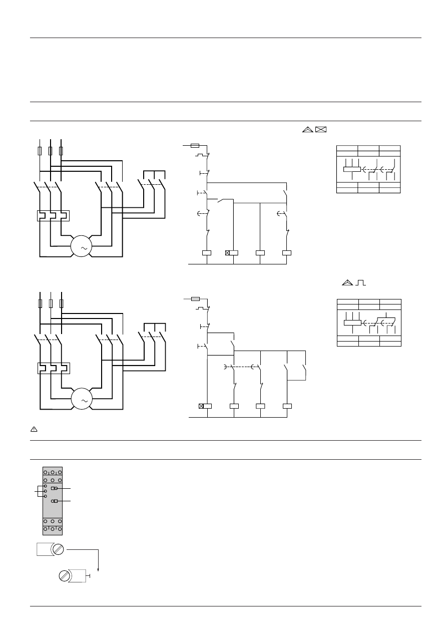
2 8 4 5 6 / 3
Te
Zelio Time timing relays
Relay output, width 22.5 mm, universal
Timing relays for star-delta starting
Schemes, setting-up
Schemes
(Star-delta starter application)
Power scheme
Control schemes
RE7-YA12BU
Star-delta function with double On-delay timing
K1T = RE7-YA relay
Power scheme
Control schemes
RE7-YR12BU
Star-delta function with contact for switching to star connection
K1T = Relay RE7-YR
No galvanic insulation between supply terminals A1, A2, B1, B2 and supply terminal Z2.
This terminal must therefore never be used (factory setting).
Setting-up procedure
1
Potentiometer for fine adjustment of the time delay, graduated in % of range max. setting
2
.
2
10-position timing range selector :
0.05…1 s
0.5…10 s
5…100 s
1.5…30 min
1.5…30 h
0.15…3 s
1.5…30 s
15…300 s
15…300 min
15…300 h
3
LEDs, depending on model :
- Green LED: flashes during the time delay period (except the first 2 timing ranges), permanently on
outside the time delay period
- Yellow LED 1: on when 1
st
relay is energised
- Yellow LED 2: on when 2
nd
relay is energised
Adjustment of the time delay
- Select the timing range immediately greater than the time required using selector switch
2
.
Example: required time 12 s; range selected 30 s.
- Using potentiometer
1
display the required time as a % of value
2
.
t x 100
12 x 100
1
= ––––––
i.e.
––––––– = 40
2
30
1
Characteristics :
pages 28450/2 and 28450/3
References :
page 28456/2
Dimensions :
page 28458/2
V2
U2
W2
W1
V1
U1
F2
K2
1
2
3
4
5
6
K1
1
2
3
4
5
6
M1
K3
1
2
3
4
5
6
L1
L2
L3
1
2
3
4
5
6
3
K1
A1
A2
96
F2
15
16
K1T
21
22
K3
21
22
13
14
S1
S2
K1T
A1
A2
13
14 K1
K2
A1
A2
K3
A1
A2
25
28
K1T
21
22
K1
14
13
K2
A1
15
B1
25
B2
28
26
Z2
18
16
A2
18
15
B1
A1
B2
A2
16
28
25
26
Y
N
∆
95
F3
V2
U2
W2
W1
V1
U1
F2
K2
1
2
3
4
5
6
K1
1
2
3
4
5
6
M1
K3
1
2
3
4
5
6
L1
L2
L3
1
2
3
4
5
6
3
K1
A1
A2
95
96
F2
21
22
K3
F3
21
22
13
14
S1
S2
K1T
A1
A2
K3
A1
A2
K2
A1
A2
14
13
53
54
K2
28
17
21
22
K1
18
17
K1T
K2
14
13
K1
B1
17
17
A1
B2
28
26
Z2
18
16
A2
18
B1
A1
B2
A2
16
28
17
26
Y
N
∆
1
2
3
Terminal block RE7-YA
Terminal block RE7-YR
40
30 s
x. %
1
2
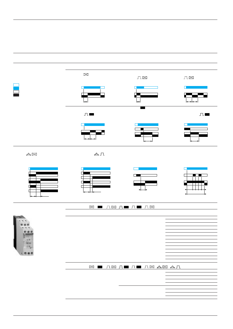
28457/2
Te
Zelio Time timing relays
Relay output, width 22.5 mm, universal
Multifunction relays
Functions, references
Multifunction relays
Adjustable time delay from 0.05 s to 300 h in 10 ranges (see setting-up procedure on page opposite).
On-delay relay
Pulse on energisation relay
Flashing relay with
RE7-ML, MY
with start on energisation
start during the ON period
RE7-ML, MY
RE7-ML, MY
Flashing relay with
Off-delay relay
Pulse on energisation relay with
start during the OFF period
RE7-ML, MY
start on opening of the
RE7-ML, MY
external control contact
RE7-ML, MY
Relay for star-delta starters with:
External control for
External control for
double On-delay timing
contact for switching to star
start of time delay
partial stop of time delay
RE7-MY
connection RE7-MY
(example on On-delay function) (1) (example on pulse on energisation
RE7-ML, MY
relay) (1)
RE7-ML, MY
6 function relay
, , , ,
Functions (see diagrams
Supply
Relay
Reference
Weight
above)
voltages
output
kg
On-delay relay
a
or
c
24 V
1 C/O
RE7-ML11BU
0.150
Off-delay relay
a
or
c
42…48 V
Pulse on energisation relay
c
110…240 V
- start on energisation
- start on opening of remote
control contact
Flashing relay with start during the OFF period
Flashing relay with start during the ON period
External control possible for:
- start of time delay
- partial stop of time delay
- adjustment of time delay (2)
8 function relay , , , , , ,
As for 6 function relay (3) +
a
or
c
24 V
2 C/O (4) RE7-MY13BU
0.150
Relay for star-delta
c
110 …240 V
starting
- with double On-delay timing
- with contact for switching
to star connection
a
or
c
24…240 V
2 C/O (4) RE7-MY13MW
0.150
(1) For use on other functions, please see the diagrams relating to the single function products.
(2) By external potentiometer, to be ordered separately. If external potentiometer is fitted, the internal potentiometer is
automatically disconnected.
(3) Except control of partial stop of time delay for RE7-MY13BU.
(4) A switch on the front face of the relay allows the second changeover contact to be used in instantaneous mode.
1
1
RE7-MY
Supply
C/O1
star
delta
Supply
C/O1
C/O2
star
delta
Supply
Start
C/O
Supply
Partial stop
C/O
Supply
C/O
Supply
C/O
Supply
Start
C/O
Supply
C/O
Supply
C/O
de-energised
energised
open
closed
t: adjustable time delay
t = t1 + t2 + t3
ts: partial stop time
1
1
1
Supply
Start
C/O
15/18
X1Z2
15/16
ts
ts
t1
t2
t
t3
15/18 (25/28)
Y1Z2
15/16 (25/26)
t
15/18
15/16
(Y1Z2)
t
15/18 (25/28)
15/16 (25/26)
t
15/18 (25/28)
15/16 (25/26)
t
t
15/18 (25/28)
Y1Z2
15/16 (25/26)
t
15/18 (25/28)
15/16 (25/26)
t
15/18 (25/28)
15/16 (25/26)
t
t
t
50 ms
17/18
17/28
t
50 ms
15/18
15/16
25/28
25/26
1
1
1
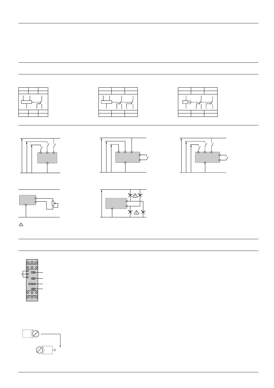
28457/3
Te
Zelio Time timing relays
Relay output, width 22.5 mm, universal
Multifunction relays
Schemes, setting-up
Schemes
Terminal blocks
RE7-ML11BU
RE7-MY13BU
RE7-MY13MW
Recommended application schemes
Start on energisation
Start by external control
External control of partial stop
Potentiometer wiring
Wiring precautions
No galvanic insulation between supply terminals A1, A2, B1, B2 and control inputs X1, Y1, Z1, Z2.
(1)
c
110…240 V: RE7-ML11BU or RE7-MY13BU,
a
or
c
24…240 V: RE7-MY13MW.
(2)
c
or
a
42…48 V: RE7-ML11BU.
(3)
c
or
a
24 V: RE7-ML11BU or RE7-MY13BU.
Setting-up procedure
1
Potentiometer for fine adjustment of the time delay, graduated in % of range max. setting
2
.
2
10-position timing range selector:
0.05…1 s
5…100 s
15…300 min
0.15…3 s
15…300 s
1.5…30 h
0.5…10 s
1.5…30 min
15…300 h
1.5…30 s
3
10-position function selector switch (positions which are not used have no marking; the output relay(s)
stay(s) in the Off position, whatever the control instructions are).
4
Switch for converting the second changeover contact to instantaneous mode (depending on model).
5
LEDs, depending on the model:
- Green LED: flashes during the time delay period (except for the first 2 timing ranges), permanently on
outside the time delay period.
- Yellow LED 1: on when 1
st
relay is energised.
- Yellow LED 2: on when 2
nd
relay is energised.
Adjustment of the time delay
- Select the timing range immediately greater than the time required, using selector switch
2
.
Example: required time 12 s; range selected 30 s.
- Using potentiometer
1
display the required timing value as a % of value
2
.
t x 100
12 x 100
1
= ––––––
i.e.
––––––– = 40
2
30
B1
A1
B2
A2
X1
Z2
(3)
(2)
(1)
(3)
(2)
(1)
B1
A1
B2
A2
1
2
4
3
5
Z1
Z2
A2
A1
15
B1
Z1
B2
Y1
X1
Z2
18
16
A2
18
15
B1
A1
A2
16
A1
15
B1
25 (21)
Z1
Y1
26 (22)
28 (24)
Z2
18
16
A2
18
15
B1
A1
A2
16
28
(24)
25
(21)
26
(22)
A1
15
Y1
25 (21)
Z1
X1
26 (22)
28 (24)
Z2
18
16
A2
18
15
A1
A2
16
28
25
26
(24)
(21)
(22)
B1
A1
B2
A2
Y1
Z2
(3)
(2)
(1)
A2
Z2
Supply
X1 or Y1 or Z1
40
30 s
x. %
1
2
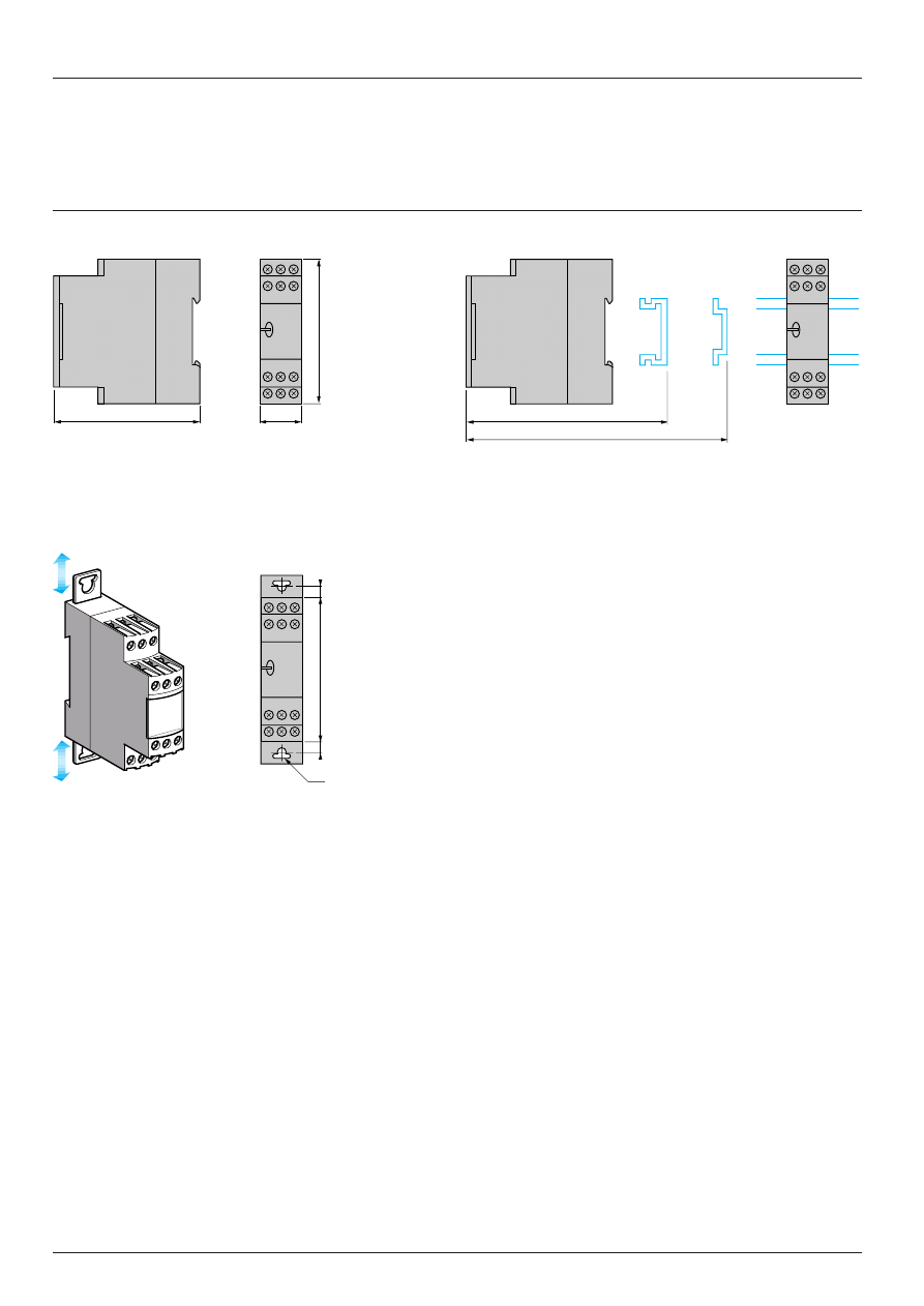
2 8 4 5 8 / 2
Te
Zelio Time timing relays
Relay output, width 22.5 mm, universal
Dimensions, mounting
RE7
Dimensions
Rail mounting
Screw fixing
Characteristics :
pages 28450/2 and 28450/3
References :
pages 28451/2 to 28457/2
Setting-up :
page 28458/3
22,5
80
78
89,5
82
Ø4
6
6
78
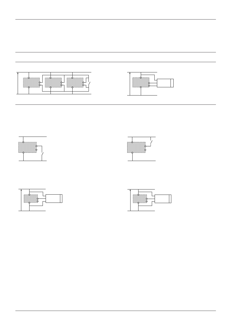
Te
2 8 4 5 8 / 3
Z2
A2
Z2
A2
Z2
A2
BN
BK
NPN
PNP
BU
Y1
–
+
Z2
A2
Zelio Time timing relays
Relay output, width 22.5 mm, universal
Schemes
Schemes
Control of several relays with a single external control contact
Connection of Telemecanique 3-wire NPN or PNP sensor
It is advisable to follow the recommended wiring schemes detailed above and on previous pages. However, the connections below are possible if the restrictions
given are taken into account.
Connection of an external control contact without using terminal Z2:
- possible on all RE7 relays with external control option except RE7-RA11BU
- d.c. supply only
Connection of a Telemecanique 3-wire NPN or PNP sensor without using terminal Z2:
- only possible on relay RE7-
iiii
BU
- d.c. supply only
Characteristics :
pages 28450/2 and 28450/3
References :
pages 28451/2 to 28457/2
Dimensions :
page 28458/2
Schemes :
pages 28451/3 to 28458/2
BN
BK
PNP
BU
Y1
–
+
B1B2
Z2
A2
24
or
48 V
–
+
Z2
A2
–
+
Z2
A2
BN
BK
NPN
BU
Y1
–
+
B1B2
Z2
A2
Y1 or X1
Y1 or X1
Y1 or X1
Y1 or X1
Y1 or X1
24
or
48 V
24
or
48 V
A1, B1 or B2
A1, B1 or B2
A1, B1 or B2
Supply
A1, B1 or B2
A1, B1 or B2
A1, B1 or B2
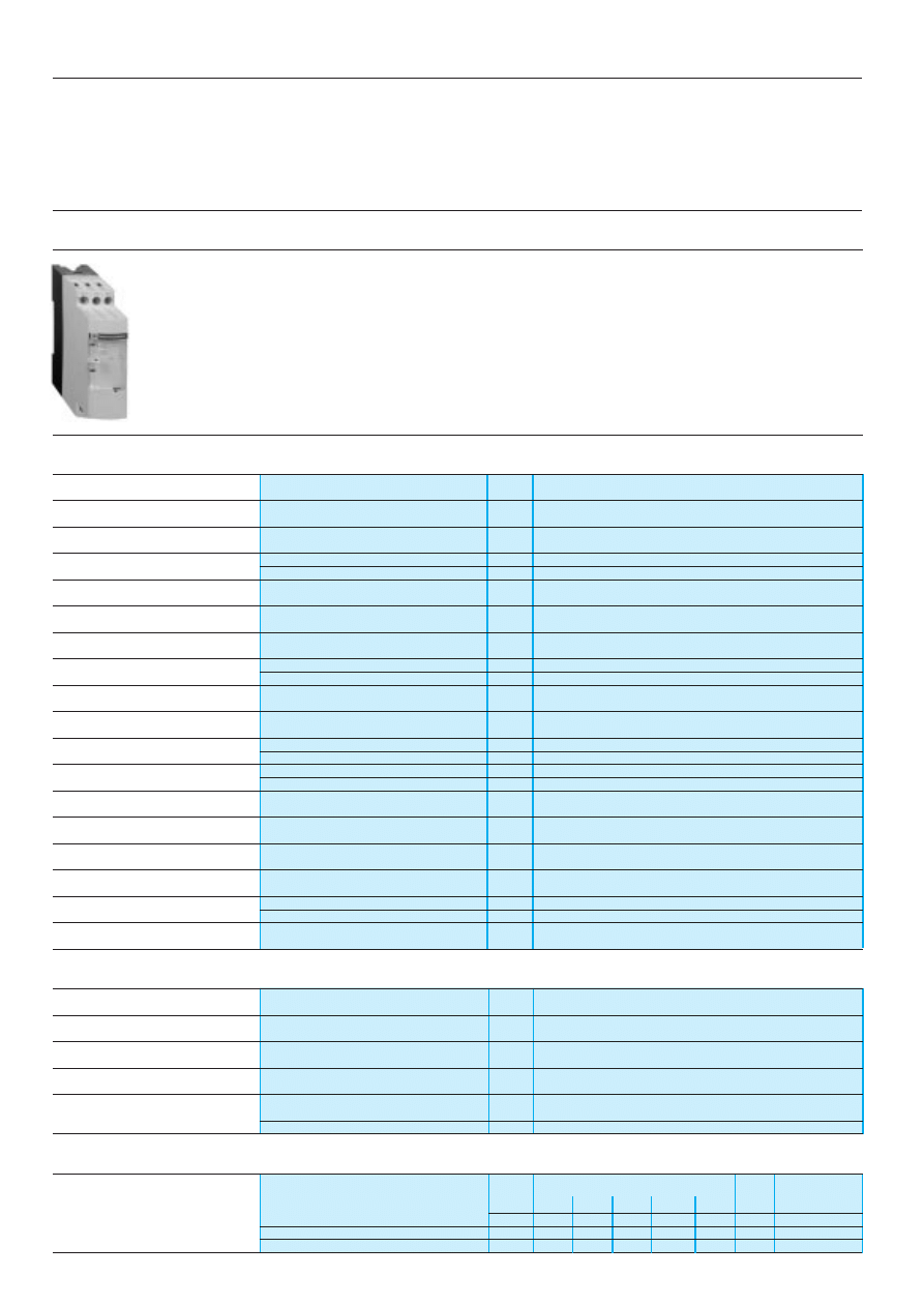
Te
2 8 4 6 1 / 2
Zelio Time timing relays
Relay output, width 22.5 mm, optimum
General characteristics
Presentation
The RE8 range of relays is designed for simple and repetitive applications, providing basic functions.
Each relay comprises:
- a single timing range,
- a C/O output relay.
These products have a transparent, hinged flap on their front face to prevent any accidental alteration of the settings.
This flap can be directly sealed.
Environment
Conforming to standards
IEC 61812-1, EN 61812-1
Product approvals
CSA, GL pending, UL
è
marking
Zelio Time timing relays conform to European regulations
relating to
è
marking
Ambient air temperature
Storage
°
C
- 40…+ 85
around the device
Operation
°
C
- 20…+ 60
Permissible relative humidity range
Conforming to IEC 60721-3-3
15…85 % Environmental class 3K3
Vibration resistance
Conforming to IEC 6068-2-6, 10 to 55 Hz
a = 0.35 ms
Shock resistance
Conforming to IEC 6068-2-27
15 gn - 11 ms
Degree of protection
Casing
IP 50
Terminals
IP 20
Degree of pollution
Conforming to IEC 60664-1
3
Overvoltage category
Conforming to IEC 60664-1
III
Rated insulation voltage
Conforming to IEC
V
250
Conforming to CSA
V
300
Test voltage for
Dielectric test
kV
2.5
insulation tests
Shock wave
kV
4.8
Voltage limits
Power supply circuit
0.9…1.1 Uc
Frequency limits
Power supply circuit
Hz
50/60
±
5 %
Disconnection value
Power supply circuit
> 0.1 Uc
Mounting position
In relation to normal vertical
Any position
without derating
mounting plane
Connection
Flexible cable without cable end
mm
2
2 x 2.5
maximum c.s.a.
Flexible cable with cable end
mm
2
2 x 1.5
Tightening torque
N.m
0.6…1.1
Immunity to electromagnetic interference (EMC)
(Application class 2 conforming to EN 61812-1)
Electrostatic discharge
Conforming to IEC 61000-4-2
Level 3 (6 kV contact, 8 kV air)
Electromagnetic fields
Conforming to IEC 61000-4-3
Level 3 (10 V/m)
Fast transients
Conforming to IEC 61000-4-4
Level 3 (2 kV)
Shock waves
Conforming to IEC 61000-4-5
Level 3 (2 kV)
Radiated and
CISPR11
Group 1 class A
conducted emissions
CISPR22
Class A
Consumption
Consumption
c
a
24 V
110 V 240 V 380 V
415 V
24 V
RE8-TA, RA, CL, PE, PU, PT
VA
0.7
1.8
8.5
–
–
W
0.5
RE8-YG, RB
VA
0.9
2.5
13
–
–
W
0.5
RE8-YA
VA
0.9
2.5
13
8
9
W
0.7
References :
pages 28462/2 and 28463/2
Dimensions :
page 28464/2
Schemes, setting-up :
pages 28462/3, 28463/3 and 28464/3
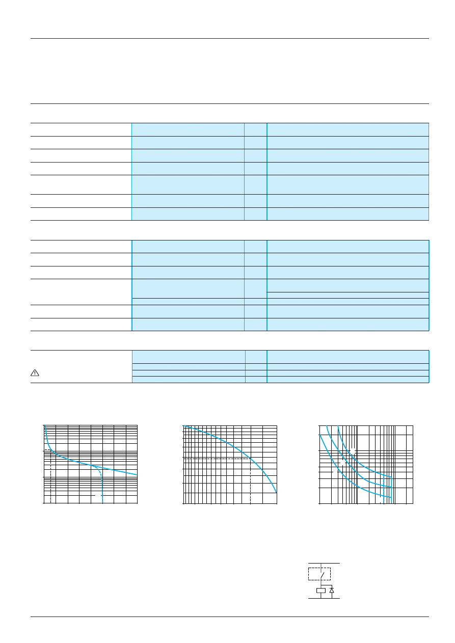
2 8 4 6 1 / 3
Te
Zelio Time timing relays
Relay output, width 22.5 mm, optimum
General characteristics
(continued)
Time delay characteristics
Setting accuracy
As % of the full scale value
±
20 %
Repeat accuracy
< 1 %
Influence of voltage
In the voltage range, 0.9…1.1 Un
< 2.5 %
Influence of temperature
< 0.2 %/
°
C
Immunity to
micro-breaks
ms
3
Minimum control pulse
ms
26 (except RE8-YG: 60)
Reset time
ms
50
Output circuit characteristics
Maximum switching voltage
V
z
250
Mechanical durability
In millions of operating cycles
20
Current limit Ith
A
8
Rated operational limits at 70
°
C
24 V
115 V
250 V
Conforming to IEC 60947-5-1/1991
AC-15
A
3
3
3
and VDE 0660
DC-13
A
2
0.2
0.1
Minimum switching capacity
12 V/10 mA
Contact material
Nickel Silver 90/10
Remote control input characteristics
Signal delivered by
No-load voltage
Supply voltage
control input Y1
Switching current
mA
< 10
No galvanic insulation between
Maximum distance
m
50
this input and the power supply
Compatibility
a
2-wire sensors with leakage current < 1 mA
a.c. load
d.c. load
Curve 1
Curve 2
Load limit curve
Electrical durability of contacts on resistive
Reduction factor k for inductive loads
load in millions of operating cycles
(applies to values taken from the
durability curve opposite)
A
RE8-RB
ii
BUTQ
A
RE8-RB
ii
BUTQ
1
L/R = 20 ms
Example:
2
L/R with load protection diode
3
Resistive load
An LC1-F185 contactor supplied with 115 V/50 Hz for a consumption of 55 VA or a current
consumption equal to 0.1 A and cos
ϕ
= 0.3
For 0.1 A, curve 1 indicates a durability of approximately 1.5 million operating cycles.
As the load is inductive, it is necessary to apply a reduction coefficient k to this number of
cycles, as indicated by curve 2.
For cos
ϕ
= 0.3: k = 0.6
The electrical durability therefore becomes:
1.5 10
6
operating cycles x 0.6 = 900 000 operating cycles
1
0,6
0,5
0,9
0,8
0,7
0,4
0,3
1
0,8
0,6 0,5
0,4
0,3
0,2
Current broken in A
Power factor on breaking (cos
ϕ
)
Current in A
Millions of operating cycles
Reduction factor k
Voltage in V
RE8
K
+
–
References :
pages 28462/2 and 28463/2
Dimensions :
page 28464/2
Schemes, setting-up :
pages 28462/3, 28463/3 and 28464/3
10
1
0,1
0,01
0
1
2
3
4
5
6
7
8
A
300
40
30
200
100
50
20
10
0,1
0,2
0,5
1
2
5
20
10
1
2
3
A
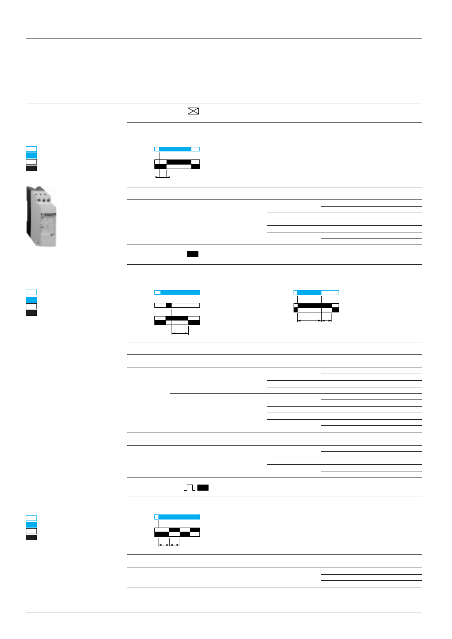
2 8 4 6 2 / 2
Te
Zelio Time timing relays
Relay output, width 22.5 mm, optimum
On-delay, Off-delay, flashing relays
Functions, references
On-delay relays
On-delay relay
Start on energisation
RE8-TA
Composition
Supply
Quantity
Timing
Reference
Weight
voltages
per pack
range (1)
kg
1 C/O
z
24 V
10
0.1 s…3 s
RE8-TA61BUTQ
0.110
c
110…240 V
0.1 s…10 s
RE8-TA11BUTQ (2)
0.110
0.3 s…30 s
RE8-TA31BUTQ (2)
0.110
3 s…300 s
RE8-TA21BUTQ (2)
0.110
20 s…30 min.
RE8-TA41BUTQ
0.110
Off-delay relays
Off-delay relay
With control contact
Self-powered
RE8-RA
RE8-RB
Composition
Supply
Quantity
Timing
Reference
Weight
voltages
per pack
range (1)
kg
Control contact
1 C/O
z
24 V
10
0.1 s…10 s
RE8-RA11BTQ (2)
0.110
0.3 s…30 s
RE8-RA31BTQ
0.110
3 s…300 s
RE8-RA21BTQ (2)
0.110
c
110…240 V
10
0.1 s…10 s
RE8-RA11FUTQ (2)
0.110
0.3 s…30 s
RE8-RA31FUTQ
0.110
3 s…300 s
RE8-RA21FUTQ (2)
0.110
20 s…30 min.
RE8-RA41FUTQ
0.110
Self-powered
1 C/O
z
24 V
10
0.05 s…0.5 s
RE8-RB51BUTQ
0.110
c
110…240 V
0.1 s…10 s
RE8-RB11BUTQ
0.110
0.3 s…30 s
RE8-RB31BUTQ
0.110
Flashing relays
Symmetrical
RE8-CL
Composition
Supply
Quantity
Timing
Reference
Weight
voltages
per pack
range (1)
kg
1 C/O
z
24 V
10
0.1 s…10 s
RE8-CL11BUTQ
0.110
c
110…240 V
(1) For easier adjustment, it is preferable to set the time delay between the maximum value in the range and one tenth
of this value.
Example: RE8-TA11BUTQ timing range 0.1 s…10 s, recommended use 1 s…10 s.
(2) Also available in pack of one; delete TQ from the end of the reference. Example: RE8-TA11BU.
de-energised
energised
open
closed
t: adjustable On-delay
Characteristics :
pages 28461/2 and 28461/3
Dimensions :
page 28464/2
Schemes, setting-up :
pages 28462/3 and 28464/3
Supply
C/O
15/18
15/16
t
de-energised
energised
open
closed
t: adjustable Off-delay
Supply
C/O
Supply
Start
C/O
15/18
15/16
t
de-energised
energised
open
closed
t = flashing time
Supply
C/O
15/18
15/16
t
t
RE8-TA
15/18
15/16
t
> 80 ms
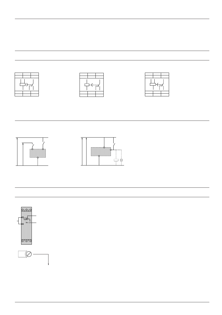
Te
2 8 4 6 2 / 3
Zelio Time timing relays
Relay output, width 22.5 mm, optimum
On-delay, Off-delay, flashing relays
Schemes, setting-up
Schemes
Terminal blocks
RE8-TA, CL
RE8-RA
RE8-RB
Recommended application schemes
RE8-TA, RB, CL
RE8-RA
Setting-up
1
Potentiometer for fine adjustment of the time delay, graduated in % of range max. setting
2
.
2
Marking of maximum time delay value.
3
LEDs, depending on the models :
- Yellow LED: illuminates when the output relay is energised,
- Green LED: illuminates when the RE8 is energised.
Adjustment of the time delay
- The maximum value of the timing range is printed on the product,
2
.
Example: RE8-TA61BUTQ; maximum time delay: 3 s.
- Time required 2.4 s; using potentiometer
1
set the value of the time delay required as a % of value
2
:
t x 100
2.4 x 100
value
1
= –––––– = –––––––– = 80
2
3
A1
15
B1
18
16
A2
18
15
B1
A2
A1
16
Characteristics :
pages 28461/2 and 28461/3
References :
page 28462/2
Dimensions :
page 28464/2
z
24 V
c
110 … 240 V
B1
A2
A1
3
1
2
A1
15
Y1
18
16
A2
18
15
A2
A1
16
A1
15
B1
18
16
A2
18
15
B1
A2
A1
16
A1
A2
Y1
c
110 … 240 V
c
24 V
a
24 V
+
–
80
3 s
x. %
1
2
Start
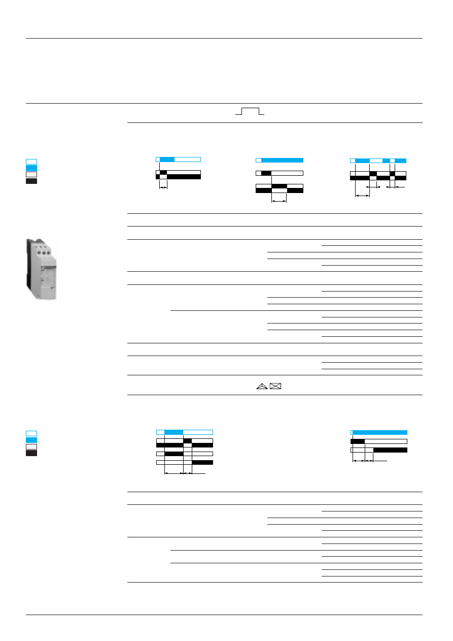
2 8 4 6 3 / 2
Te
Zelio Time timing relays
Relay output, width 22.5 mm
Pulse on energisation relays, relays for star-delta starters
Functions, references
Pulse on energisation relays
Start on
Start on opening of
Start on
energisation
external control contact
de-energisation
RE8-PE
RE8-PD
RE8-PT
Composition
Supply
Quantity
Timing
Reference
Weight
voltages
per pack
range (1)
kg
On energisation
1 C/O
z
24 V
10
0.1 s…10 s
RE8-PE11BUTQ
0.110
c
110…240 V
0.3 s…30 s
RE8-PE31BUTQ
0.110
3 s…300 s
RE8-PE21BUTQ
0.110
By control contact
1 C/O
z
24 V
10
0.1 s…10 s
RE8-PD11BTQ
0.110
0.3 s…30 s
RE8-PD31BTQ
0.110
3 s…300 s
RE8-PD21BTQ
0.110
c
110…240 V
10
0.1 s…10 s
RE8-PD11FUTQ
0.110
0.3 s…30 s
RE8-PD31FUTQ
0.110
3 s…300 s
RE8-PD21FUTQ
0.110
On de-energisation
1 C/O
z
24 V
10
0.05 s…1 s
RE8-PT01BUTQ
0.110
c
110…240 V
Timing relays for star-delta starters
Timing relays for star-delta starters
With contact for switching to star connection
With double On-delay period
RE8-YG (2)
RE8-YA
Composition
Supply
Quantity
Timing
Reference
Weight
voltages
per pack
range (1)
1 C/O
z
24 V
10
0.1 s…10 s
RE8-YG11BUTQ
0.110
c
110…240 V
0.3 s…30 s
RE8-YG31BUTQ
0.110
3 s…300 s
RE8-YG21BUTQ
0.110
1 N/C + 1 N/O
z
24 V
10
0.3 s…30 s
RE8-YA32BTQ
0.110
c
110…240 V
10
0.3 s…30 s
RE8-YA32FUTQ
0.110
c
380…415 V
10
0.3 s…30 s
RE8-YA32QTQ
0.110
(1) For easier adjustment, it is preferable to set the time delay between the maximum value in the range and one tenth
of this value.
Example: RE8-PE11BUTQ timing range 0.1 s…10 s, recommended use 1 s…10 s.
(2) Correct operation of the star-delta starter is only possible if the wiring scheme on page 28463/3 is strictly complied
with.
de-energised
energised
open
closed
t: pulse time
Characteristics :
pages 28461/2 and 28461/3
Dimensions :
page 28464/2
Schemes, setting-up :
pages 28463/3 and 28464/3
Supply
C/O
Supply
Start
C/O
15/18
Y1A1
15/16
t
15/18
15/16
t
1
Supply
C/O
de-energised
energised
open
closed
t: adjustable time delay (star)
t
50 ms
15/18
15/16
RE8-PE
Supply
N/C
N/O
15/18
15/16
t
< t
> 80 ms
t
80 ms
15/16
25/28
Supply
star
delta
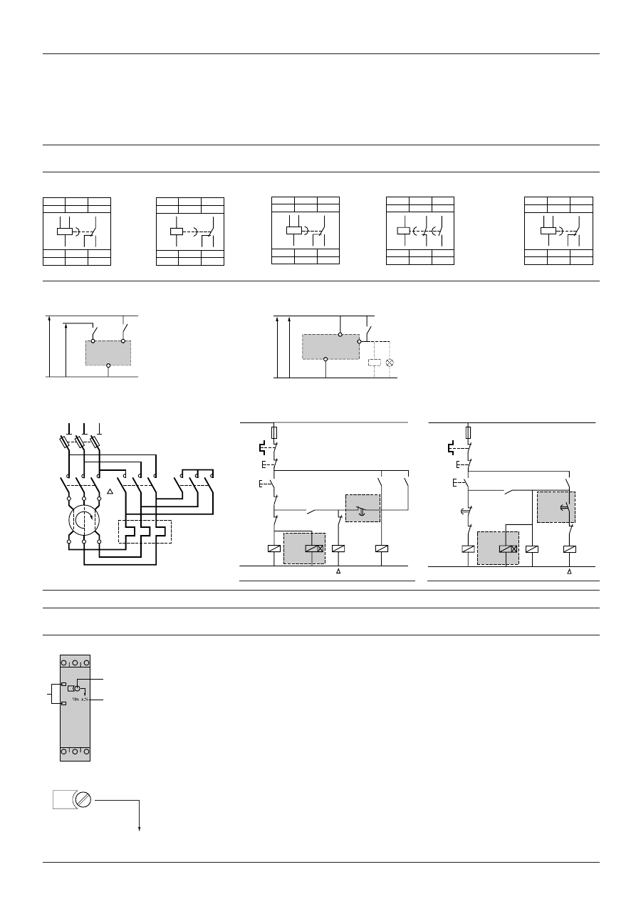
Te
2 8 4 6 3 / 3
Zelio Time timing relays
Relay output, width 22.5 mm, optimum
Pulse on energisation relays, relays for star-delta starters
Schemes, setting-up
Schemes
Terminal blocks
RE8-PE
RE8-PD
RE8-PT
RE8-YA
RE8-YG
Recommended application schemes
Pulse on energisation relays
RE8-PE, PT
RE8-PD
Timing relays for star-delta starters
RE8-YG, RE8-YA
RE8-YG
RE8-YA
(1) K1T: RE8-YG
i
1
ii
TQ
(1) K1T: RE8-YA32
ii
TQ
Note: Correct operation of the star-delta starter associated with the RE8-YG is only possible if the wiring scheme is strictly complied with.
Setting-up
1
Potentiometer for fine adjustment of the time delay, graduated in % of range max. setting
2
.
2
Marking of maximum time delay value.
3
LEDs, depending on the models :
- Yellow LED: illuminates when the output relay is energised,
- Green LED: illuminates when the RE8 is energised.
Adjustment of the time delay
- The maximum value of the timing range is printed on the product
2
.
Example: RE8-PE11BUTQ; maximum time delay: 10 s.
- Time required 2.4 s; using potentiometer
1
set the value of the time delay required as a % of value
2
:
t x 100
2.4 x 100
value
1
= –––––– = –––––––– = 24
2
10
Characteristics :
pages 28461/2 and 28461/3
References :
page 28463/2
Dimensions :
page 28464/2
A1
A2
Y1
c
110 … 240 V
c
24 V
a
24 V
+
–
z
24 V
c
110 … 240 V
B1
A2
A1
A1
15
Y1
18
16
A2
18
15
A2
A1
16
A1
15
B1
18
16
A2
18
15
16
B1
A2
A1
A1
15
B1
18
16
A2
18
15
B1
A2
A1
16
A1
15
25
28
16
A2
16
15
A2
A1
28
25
A1
15
B1
18
16
A2
18
15
16
B1
A2
A1
– KM3
– KM2
– K1T
(1)
– KM1
Y
A1
A2
A1
A2
A1
A2
A1
A2
– KM3
– KM2
– KM1
– S2
– KM1
– K1T
(1)
16
15
– KM1
– KM2
– S1
– FU1
– Rth
L
– KM2
– KM3
– KM1
U1
V1
W1
U2
V2
W2
– Q1
L1
L2
L3
– Rth
Y
– KM2
– KM3
– K1T
(1)
– KM1
Y
A1
A2
A1
A2
A1
A2
A1
A2
– KM3
– KM2
– KM1
– S2
– KM1
– K1T
– K1T
15
16
25
28
– S1
– FU1
– Rth
L
3
1
2
24
10 s
x. %
1
2
Start

2 8 4 6 4 / 2
Te
Zelio Time timing relays
Relay output, width 22.5 mm, optimum
Dimensions, mounting
RE8
Dimensions
Rail mounting
Screw fixing
Characteristics :
pages 28461/2 and 28461/3
References :
pages 28462/2 and 28463/2
Schemes, setting-up :
pages 28462/3, 28463/3 and 28464/3
22,5
80
78
89,5
82
Ø 4
6
6
78
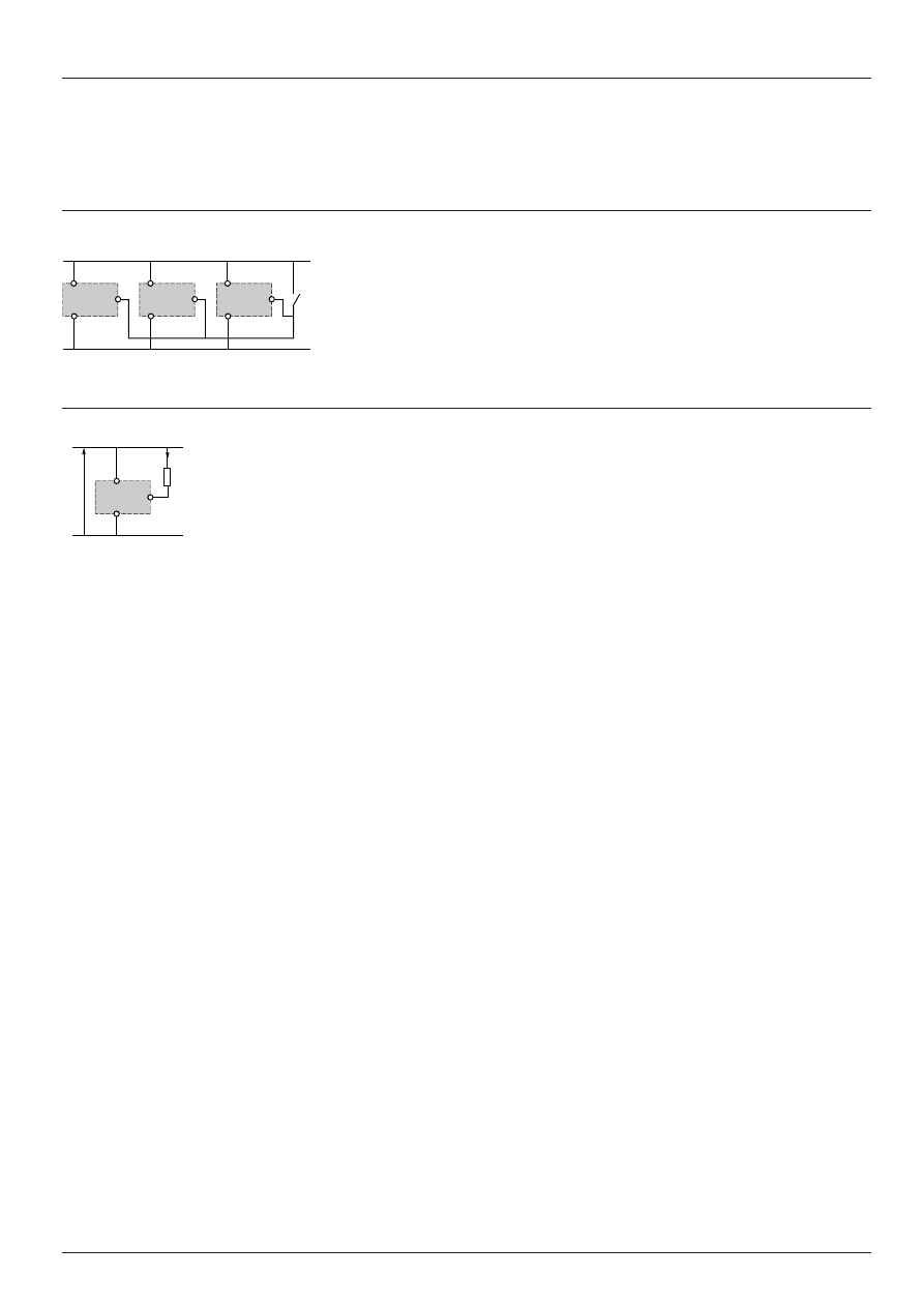
Te
2 8 4 6 4 / 3
Zelio Time timing relays
Relay output, width 22.5 mm, optimum
Schemes
Control of several relays with a single external control contact
RE8-RA, PD
The external control contact C may be an electronic control device, for example a 2-wire sensor. In this case A1-A2 =
a
24 V and the control device can only control
up to a maximum of 4 relays.
Connection of a
a
2-wire sensor
Leakage current (open state) If < 1 mA.
Characteristics :
pages 28461/2 and 28461/3
References :
pages 28462/2 and 28463/2
Dimensions :
page 28464/2
Setting-up :
pages 28462/3 and 28463/3
Y1
A2
Y1
A2
Y1
A2
A1
A1
A1
C
Y1
–
+
A1
A2
If
Document Outline
Wyszukiwarka
Podobne podstrony:
02 ZELIO CONTROL CATALOGUE
02 ZELIO CONTROL CATALOGUE
04 1b Zelio Time RE7 instr uzytkid 4953
04 1b Zelio Time RE7 instr uzytk
04 1a ZELIO TIME CONTROL PANORA Nieznany (2)
04 1b Zelio Time RE8 RE9 instr uzytk
02 PHASEO POWER SUPPLIES CATALOGUE
Simon Hawke Time Wars 02 The Timekeeper Conspiracy v1 0
FIDE Trainers Surveys 2015 02 26 Reynaldo Vera Time Trouble
Asprin, Robert Time Scout 02 Wagers of Sin
Jon Scieszka Time Warp Trio 02 The NOT So Jolly Roger
więcej podobnych podstron