
C
H
A
P
T
E
R
16
F
IBER
O
PTIC
R
ESTORATION
L A R R Y J O H N S O N
Fiber optic technology has provided communications users with the ability to
transmit longer distances with increased amounts of information. This has paral-
leled the growth in communications provided by computers, fax machines, cellu-
lar services, and video using digital transmission systems. Fiber optics has been
used mostly in backbones due to its capability to handle vast amounts of infor-
mation, whether from city to city or file servers to users in campus applications.
As the growth of these industries increases, so does our reliance on the fiber
systems being used for the transmission. Telephone companies and other service
providers have routines and disciplines well established for restorations. Their
long spans in exposed aerial and direct buried applications make restoration
practices critical to the operation of their communications systems.
Local area networks (LANs) are unique in that they consist of intra- and
interbuilding links of relatively short distances when compared to the various
types of wide area and metropolitan networks using optical communications.
This requires different approaches and equipment to be responsive to emergency
restorations.
167

PROACTIVE PLANNING VERSUS REACTIVE RESTORATIONS
All networks start at the conceptual design stage. During this stage we must
establish a value to the type of posture we should take for providing for the phys-
ical plant and its protection. Since the establishment of the Fiber Distributed Data
Interface (FDDI) standard in the late 1980s, we have seen a serious effort to pro-
vide protection in both the network and physical routing of optical communica-
tions systems. Why? FDDI was designed as a backbone system operating at 100
Mb/s. With this large amount of data, users wanted reliability to assure that their
entire data systems would not fail in case of either node or cable failure. FDDI’s
counterrotating ring offered route redundancy, optical bypass switches for net-
work protection, and diagnostics for system management.
Today’s designers should learn from these lessons. Networks with high data
rates, critical reliability, security, and priority users should be designed for route
diversity. Route diversity means two specific different routes (not putting two
cables in the same duct). This, of course, can create a cost issue in both materi-
als and construction. For example, if a campus is built on a system of steam tun-
nels in a star topology, the expense would be high to create a physical ring. But
the tradeoffs between network reliability and cost must be made at the design
stage.
Types of Faults
Another issue to review in the design stage is the types of failures that have
occurred in the past. History repeats itself, even in network failures. Tables 16-1 and
16-2 show some of these failures.
A quick review of these tables allows us to identify certain areas and types of
faults.
A: Patch Panel Related
These failures occur around the patch panel. The cause could be improper dress-
ing of the jumpers and cables, improper keying of connectors, contamination of
the connection, or improper cable routing and localized damage.
B: System Related
Over- or underdriving the optical transmission still causes either total or inter-
mittent failure.
C: Installation Related
Improper bend radius, clamping of the cables, and improper rolls of the trans-
mit/receive fibers are common types of problems. Installations occurring around
previously installed fiber networks can also create failures due to lack of atten-
tion in dressing, termination, and cable routing.
168
CHAPTER 16 — FIBER OPTIC RESTORATION

CHAPTER 16 — FIBER OPTIC RESTORATION
169
Table 16-1
Typical Cable System Faults
Fault
Cause
Equipment
Remedy
Bad connector
Dirt or damage
Microscope
Cleaning/
polishing/
retermination
Bad pigtail
Pigtail kinked
Visual fault locator
Straighten kink
Localized cable
Kinked cable
OTDR
Straighten kink
attenuation
Distributed increase
Defective cable
OTDR
Reduce stress/
in cable attenuation
or installation
replace
specifications
exceeded
Lossy splice
Increase in splice
OTDR
Open and redress
Loss due to
Visual fault locator
fiber stress in
closure
Fiber break
Cable damage
OTDR
Repair/replace
Visual fault locator
Table 16-2
Typical Causes of Failures in LANs
No.
Failure Location
Type of Failure
1
Broken fibers at connector joints
A
2
Broken fibers at patch panels
A
3
Cables damaged at patch panels
A
4
Fibers broken at patch panels
A
5
Cables cut in ceilings and walls
D
6
Cables cut through outside construction
D
7
Contaminated connections
A
8
Broken jumpers
A
9
Too much loss
B
10
Too little loss (overdriving the receiver)
B
11
Improper cable rolls
C
12
Miskeyed connectors
C
13
Transmission equipment failure
B
14
Power failure
B

D: Construction Related (Major and Minor)
Normally due to construction and work-related activities, this could be caused by
backhoes and other heavy construction equipment digging up cables. Cables can
be damaged in aerial plant due to improper installation techniques, falling
branches, automobile crashes, gunshots, and lightning. In LANs, cuts through
walls and ceilings, mistaken cutting of cables, improper clamping, and breaking
fibers at the connectors by improper handling or by accident are examples of
localized failures due to poor cable identification or lack of care by workers.
EQUIPMENT USED IN RESTORATION
1. Fiber optic cleaning kit. Many faults with optical systems are caused by
contamination of connectors, so simple cleaning will resolve these prob-
lems. Remember to keep connectors clean and capped when not in use.
(Resolves problem 7 [Table 16-2])
2. Optical inspection scope. Used to identify poor connector finishes and
surface contamination or damage. Magnification can be from 30 to 400
power. The microscope needs to have an interface to hold the connector
type securely for viewing. (Identifies problem 7 [Table 16-2])
3. Optical loss test set or test kit. Used for end-to-end loss tests. The set
consists of a stabilized light source and a calibrated power meter. The
instruments should match the operating wavelength, fiber type, and con-
nector of the transmission system. The power meter by itself is the essen-
tial go–no go instrument in fiber optic troubleshooting. This instrument
allows us to check power levels at the transmitter, receiver, and at any
connection point in a system to isolate whether the problem is with the
electro-optics (low transmitter power or proper receiver power indicat-
ing electronic problems) or the fiber optic cable plant (increased loss
beyond allowable margins). Using these instruments and good system
documentation, the user should be able to diagnose almost every net-
work fault. (Identifies power levels with problems 1–6, 8–11, and 13
[Table 16-2])
4. Visual tracers and fault locators. Inexpensive instruments that transmit
visible light through a fiber. The more powerful versions use red He, Ne,
or diode lasers operating in the visible spectrum and can locate breaks
though many types of jumpers and buffered fibers, as long as the buffer
or cable jacket is translucent. These instruments will not work on most
multifiber cables or black- or gray-jacketed single-fiber cables. White
light and red LED versions are also available but do not have the power
to locate internal breaks. (Identifies problems 1–3, 8, 11 [Table 16-2])
170
CHAPTER 16 — FIBER OPTIC RESTORATION

5. Optical Time Domain Reflectometer (OTDR). The instrument everyone
often considers first in restorations is the most application dependent. In
long-distance networks where most outages occur far away from the end
equipment, the OTDR is critical for a restoration posture. In the case of
LANs, most problems cannot easily be identified with the OTDR, since
its distance resolution makes most short cables impossible to view. In a
LAN, cable plants must be diagnosed through the use of the above men-
tioned types of equipment, unless one is dealing with a campus network
where cables are longer than 500 to 1,000 meters. Due to the high cost of
an OTDR, rental may be better than purchasing one.
IDENTIFYING THE PROBLEM
The first requirement for restoration is, of course, to identify the problem. To
guide you through that process, a flowchart is shown in Figure 16-1. First one
must determine if the problem is in the electronics or the fiber optic cable plant.
Using the power meter, unplug the connector at the receiver, measure the power
at the receiver, and compare it to the network specification. To measure the
receiver power, it is sometimes necessary to run equipment diagnostics at the
transmitter to output a test signal. If the power level is within specification, there
is most likely a problem with the transmission electronics. If this is the case, you
must call in the network specialists to diagnose the network problem.
If the receiver power is low, go to the transmitter and measure the power output
there, using a known good jumper cable and the power meter. If the power is low,
there is a transmitter problem that must be fixed. If the transmitter power is within
specification, there is too much loss in the cable plant. This must be diagnosed.
Diagnosing the cable plant can start with a visual continuity check with a
visual tracer or fault locator. If the cable plant has just been installed or rerouted
at patch panels, be certain that the correct connections have been made at every
patch panel. This requires starting at one end and tracing the fiber path through
every connection. Even if you do not find a misconnection, you will find where
the signal stops, thus identifying the segment of the cable plant with the problem.
Several problems can cause the faulty segment, including a cable cut or stress
causing loss, broken or damaged connectors, or a bad splice. If only one fiber is
affected and there are no splices in the cable, the problem is most likely a dam-
aged connector. Examining it visually for kinking of the cable or other damage,
or examining the end of the connector ferrule with the microscope may show the
fault. If the cable is short, like most LAN cables, a visual tracer or fault locator
can be used most effectively. The most effective tool is good cable plant records,
however, since cable cuts or damage caused by construction or erroneous cutting
can be found by following the cable route and looking for obvious damage.
CHAPTER 16 — FIBER OPTIC RESTORATION
171
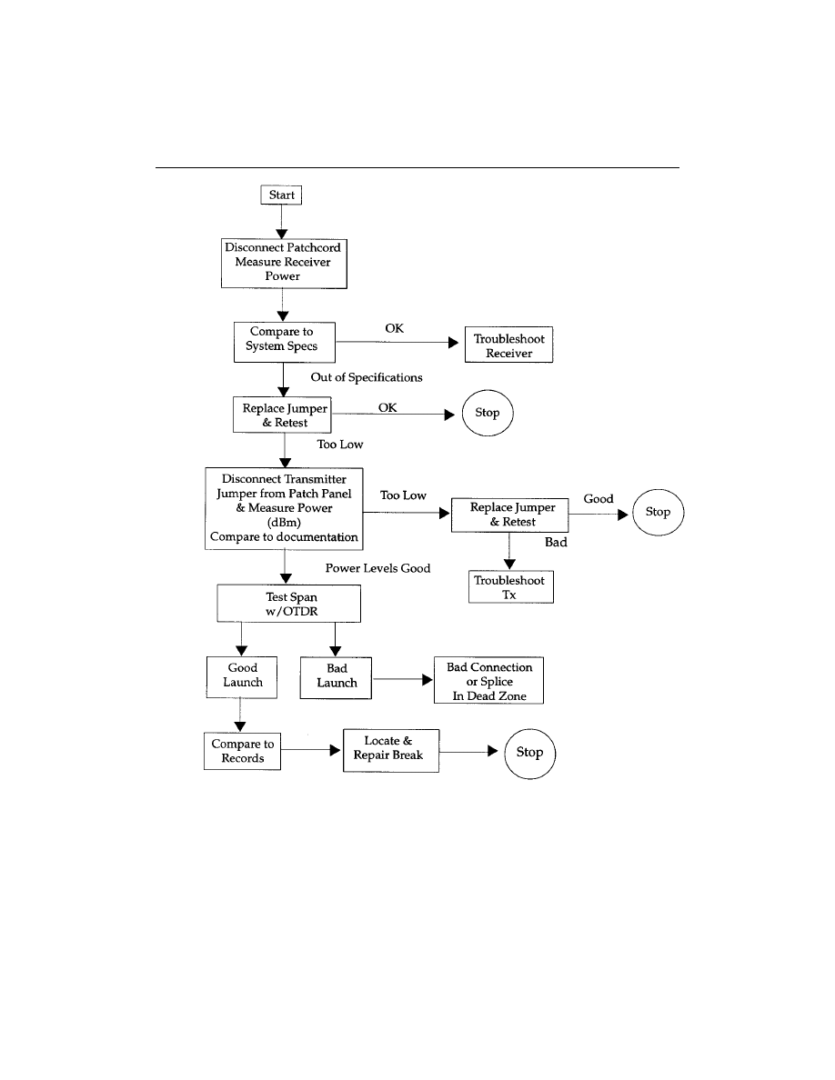
Figure 16-1
Problem identification flowchart. Courtesy The Light Brigade
172
CHAPTER 16 — FIBER OPTIC RESTORATION

If the cable is long (over 500 meters or 1,640 feet) or underground, an
OTDR may be necessary to find and diagnose the problem. But since the OTDR
has poor short-length resolution, it will not be useful in finding many LAN prob-
lems such as broken connectors on jumper cables or failures in short links. If you
are using an OTDR to find faults in multimode links, use the 850-nm range since
it has much higher resolution than the 1300-nm range and is thus more likely to
find problems.
RESTORING SERVICE
Once the fault and location have been identified, we need to restore the outage.
This sounds simple but can be complex. However, if the problem is with only one
fiber in the cable, switch to a spare fiber and replace the bad connector as time
permits. If immediate emergency restoration is necessary, consider these issues.
Basic Questions
1. Does the span have retrievable slack? If so, we can pull the slack back
and make one repair point.
2. Will it be easier, quicker, and/or less expensive to replace the section ver-
sus repairing the section?
3. Will we install connectors or use splices for the repair?
4. Either way we will need to protect the repair point(s) to prevent future
damage. This could mean adding closure(s), patch panel(s) or rerouting
of cable to other physical points.
5. Can the system handle the additional losses caused by the additional
connectors, splices, and fiber length?
6. If necessary, can we provide a drop cable over the ceiling, in the ceiling,
down the roof, and so on until we can make a permanent restoration?
WHAT ABOUT THOSE STORAGE LOOPS?
Networks and the buildings housing them must accommodate many adds, moves,
and changes over their life spans. Designers planning for these also resolve one of
the many headaches associated with LAN cable restorations. This is the issue of
retrievable slack versus nonretrievable slack.
Retrievable Slack
Cable spans designed with slack points allow for spare cable to be pulled together,
allowing for only one termination point. The use of quick mechanical splices or
CHAPTER 16 — FIBER OPTIC RESTORATION
173

direct connectorization allows for restoration to take place with minimal losses.
Because most cables within the building are of the breakout or distribution styles,
these allow for easy retermination. The main issue is how to store the splice/con-
nection panel or miniclosure. These products provide strain relief of the cable and
physical protection of the splice or connectors.
Placement could be above the floor, wall mounted, or ceiling mounted. In
most of these situations aesthetics and size will be key factors. For many users,
security and access may need to be considered. The cable should be strain relieved
and prepared, leaving as much slack as possible for future entry and possible
rerouting for future changes. (Hopefully we can use this fiber and reroute for
future needs as well.)
EMERGENCY RESTORATION (WITH RETRIEVABLE SLACK)
The cable fault has been found and the spare has been pulled back to the failure
point. We must confirm that the cable break is where it appears to be. The use of
visual light sources should be used to check each fiber from both ends. (We
would not want to have a second break point 1 foot away and not cut it out.)
The site must be checked to find the best point and method to repair the fibers.
The cables may be pulled back to a ceiling, floor, post, or other location for physical
mounting. This location should be noted on your drawings and documented. The
panel should also be labeled and possibly secured. After the cables are repaired, the
fiber spans should be retested for loss using the optical loss test set.
Nonretrievable Slack
Let us take a serious look at our options. Will it be quicker to pull in a new cable or
segment? Should I install a new segment? Should I splice or connectorize and how
do I protect these? Without retrievable slack we must add a section of cable to the
span. This will require not only two termination points but also twice the labor and
material. We must also have a length of fiber equal to or greater than the amount
of fibers in the span. As you can see, the price for not leaving slack is both more
expensive and labor consuming. The process for the determinations is the same as
the retrievable slack, except now we have two points that need to be addressed.
FIBER OPTIC RESTORATION FOR SINGLEMODE NETWORKS
Networks involving singlemode fibers tend to be more critical and more difficult
to repair than their multimode counterparts. This is due to the higher speeds and
longer distances encountered. In addition, singlemode systems tend to be directly
buried, placed by aerial methods, and in longer conduit systems. These tech-
174
CHAPTER 16 — FIBER OPTIC RESTORATION

niques usually provide an optimum amount of protection for the optical cable.
However, when they fail it is normally catastrophic. Natural disasters, construc-
tion activities, and accidents cause most of these failures.
They cause greater outages affecting more users, more lost revenue, and are a
magnitude more complex to restore. This is why singlemode users tend to have a
restoration plan in place and use slack times to practice the plan.
Summary of Suggestions
1. Prioritize your fibers. Most networks have spare fibers. When your sys-
tem is down, get the priority fibers fixed first, then worry about the
spares.
2. Have spare connectors and a connectorization kit or mechanical splice
kit available.
3. Have a trained crew that knows how to terminate and test the fiber net-
work. Have emergency phone numbers available for access.
4. Have the proper test equipment and tooling for the job.
Planning for Restoration
The Basic Recommended Restoration Posture
All users of communications systems must have a basic posture to address what
would happen should a failure occur. Following are several recommendations.
1. All fiber routes should be properly documented for both optical perfor-
mance and physical routing.
2. This should include patch panel designations, signal type, and intercon-
nect routing information.
3. All transmitters and receivers should be documented to their optical
transmit and power levels. Receivers should be documented for both
minimum and maximum power levels.
4. All spans should be documented for optical loss. This would normally be
at both 850/1300 nm for multimode applications and 1310/1550 nm for
singlemode applications. The documentation should identify the fiber
size and manufacturer.
5. If OTDR tests have been performed, copies of the OTDR traces should
be included in the test reports.
6. If cable has sequential markings, the difference between the markings
tells us the actual cable length in meters or feet for each segment. This
should be documented.
7. Fibers should be identified and prioritized to allow for priority fibers to
be quickly restored.
CHAPTER 16 — FIBER OPTIC RESTORATION
175

Restoration Planning
Imagine a system failure and having to restore a damaged optical cable. Let us
look at some of the issues that would need to be addressed.
1. How would we know of the problem?
2. Who is first advised of the outage?
3. Is there a technical team on call to respond?
4. Is this a dedicated route without backup or alternative routing? If yes,
this would require emergency restoration.
5. If not, this could be a planned restoration. Planned restorations allow for
more flexibility, providing better quality in restoration.
6. Do you have records including OTDR prints, optical power levels, up-to-
date “as built” drawings on all segments?
7. Do you have an emergency restoration program?
8. Do you have emergency restoration kits?
9. Have these been evaluated with your staff including management, engi-
neering, construction, and maintenance?
10. Are your customers prioritized? Are there any contracts and/or services that
could affect priorities (e.g., emergency services, government, military)?
11. Do you have prioritized fibers?
12. What is the time allowance for restoration?
13. Is this a restoration in which we will allow compromises on splice loss to
bring the system up and will resplice later when better prepared?
14. What is the maximum allowable splice loss for restorations?
15. Is there a vehicle available that can allow a team to work within it so that
they can work in a well-lit, dry environment with a power supply?
16. Are all necessary materials and equipment easily accessible by the team
en route to the outage?
17. How many splice and test sets do you have?
18. If using a fusion splicer, do you know the fiber types and settings for the
equipment?
19. What is the OTDR with the highest resolution?
What pulse width?
Wavelength?
Do you know the index of refraction of the fibers and manufacturers in
your system?
20. What type of communications will be used between OTDR operators
and splicers?
21. What is the limitation of this equipment?
22. What level of heavy equipment will be necessary?
23. How do you determine the location of a cable cut? Can you triangulate?
176
CHAPTER 16 — FIBER OPTIC RESTORATION

24. In the case of a single cut with retrievable slack, what equipment will be
used?
25. In the case of a cut without retrievable slack, what equipment will be
used?
Team A ______________________________________________________
Team B _______________________________________________________
Which team is quicker? _________________________________________
Which team has the most experience? _____________________________
26. In the case of massive cable failure, how many cables can you repair
simultaneously?
27. Can this restoration be done safely or will we be delayed?
28. Is there anything we can do about this?
29. Where is spare cable stored and how is it identified?
30. What else can go wrong?
31. Have we missed anything? Equipment? Environment? Staff? Tools?
Restoration (Miscellaneous Issues)
1. How do we keep the restoration plan and staff current?
2. Have you graded your staff on fiber optic restoration abilities?
3. Do you have annual/semiannual procedures for testing/evaluating exist-
ing dark fibers?
4. How are test reports filed?
5. Where are test reports filed?
6. What about updates?
7. Do these include locations where cable slack is stored?
8. Each cable segment should be evaluated for worst case failures. Has this
been done?
9. Do the emergency restoration kits (ERK)s include a bill of materials/
checklist of all tools and components and suppliers?
10. Do you have adequate amount of inventory and consumables? Are any
of these date coded?
11. Do you photograph/film your restorations? The use of film and/or pic-
tures provides a good learning and review tool. In the case of litigation
the pictures can be invaluable.
Postrestoration Recommendations
1. Redocument and retest your splices, spans, and segments.
2. Adjust your “as built” drawings. New vaults, closures, splices, and slack
cable points may need to be added or adjusted.
CHAPTER 16 — FIBER OPTIC RESTORATION
177

3. Schedule and conduct a meeting to review all aspects of the restoration.
A) What happened? What were the cause and impacts?
B) What did we do well?
C) What did not work? (Technique, equipment, products, staff)
D) How can this be resolved?
E) How can we improve?
F) What needs to be done to rebuild kits and replenish inventory?
REVIEW QUESTIONS
1. A high loss splice is found with a(n) _____________
a. OTDR.
b. microscope.
c. visual fault locator.
d. cable identifier.
2. Faults can be generalized into four categories:
1. ____________________
2. ____________________
3. ____________________
4. ____________________
3. Poor connectors are found with a(n) __________, and are best remedied
by __________
a. visual fault locator, retermination.
b. visual fault locator, cleaning.
c. microscope, cleaning.
d. microscope, retermination.
4. The best was to find a break in an accessible LAN cable is with a(n)
_____________
a. OTDR.
b. plant records.
c. visual fault locator.
d. power meter.
5. If two fibers in a 12-fiber cable show high loss, while the other 10 show
low loss, the most likely cause is _____________
a. improper bend radius.
b. improper pulling method.
c. kinked cable.
d. dirty connectors.
178
CHAPTER 16 — FIBER OPTIC RESTORATION
Wyszukiwarka
Podobne podstrony:
9 Guidelines for Fiber Optic Design and Installation
19 Appendix A Glossary of Fiber Optic Terms
5 Specifying Fiber Optic Cable
20 Appendix B Fiber Optic Standards
6 Fiber Optic Connectors, Splices, and Tools
7 Fiber Optic Hardware
17 Fiber Optic Testing
13 Fiber Optic Cable Plant Documentation
3 Fiber Optic Networks
1 The Origins of Fiber Optic Communications
14 Estimating and Bidding Fiber Optic InstallationX
11 Fiber Optic Installation Safety
15 Fiber Optic Cable Pulling
więcej podobnych podstron