
DAEWOO M-150 BL2
SECTION 1G
ENGINE EXHAUST
TABLE OF CONTENTS
Description and Operation
1G-2
. . . . . . . . . . . . . . . . . .
Exhaust System
1G-2
. . . . . . . . . . . . . . . . . . . . . . . . . . .
Muffler
1G-2
. . . . . . . . . . . . . . . . . . . . . . . . . . . . . . . . . . .
Catalytic Converter
1G-2
. . . . . . . . . . . . . . . . . . . . . . . .
Component Locator
1G-3
. . . . . . . . . . . . . . . . . . . . . . . .
Exhaust System
1G-3
. . . . . . . . . . . . . . . . . . . . . . . . . . .
Repair Instruction
1G-4
. . . . . . . . . . . . . . . . . . . . . . . . . .
On-Vehicle Service
1G-4
. . . . . . . . . . . . . . . . . . . . . . . . . .
Exhaust Pipe/Catalytic Converter
1G-4
. . . . . . . . . . . .
Pup-up Catalitic Converter
1G-5
. . . . . . . . . . . . . . . . . .
Front Muffler
1G-7
. . . . . . . . . . . . . . . . . . . . . . . . . . . . . .
Rear Muffler
1G-8
. . . . . . . . . . . . . . . . . . . . . . . . . . . . . .
Specifications
1G-9
. . . . . . . . . . . . . . . . . . . . . . . . . . . . .
Fastener Tightening Specifications
1G-9
. . . . . . . . . . .

1G – 2 ENGINE EXHAUST
DAEWOO M-150 BL2
DESCRIPTION AND OPERATION
EXHAUST SYSTEM
Notice: When you are inspecting or replacing exhaust
system components, make sure there is adequate clear-
ance from all points on the underbody to avoid possible
overheating of the floor pan and possible damage to the
passenger compartment insulation and trim materials.
Check the complete exhaust system and the nearby
body areas and tailgate for broken, damaged, missing or
mispositioned parts, open seams, holes, loose connec-
tions or other deterioration which could permit exhaust
fumes to seep into the luggage or passenger compart-
ment. Dust or water in the luggage may be an indication
of a problem in one of these areas. Any defects should
be corrected immediately.
MUFFLER
The muffler reduces the temperature, pressure, and
noise of the exhaust gas.
Aside from the exhaust manifold connection, the ex-
haust system uses a flange and seal joint design op-
posed to a slip joint coupling design with clamp. If holes,
open seams or any deterioration is discovered upon in-
spection of the front muffler and pipe assembly, the
complete assembly should be replaced. The same pro-
cedure is applicable to the rear muffler assembly.
Heat shields in the front and rear muffler assembly posi-
tions, as well as for the catalytic converter and front ex-
haust pipe, protect the vehicle and the environment from
high temperatures the exhaust system develops.
CATALYTIC CONVERTER
Notice: When jacking or lifting the vehicle from the body
side rails, be certain that the lift pads do not contact the
catalytic converter as this could damage the catalytic
converter.
Notice: The catalytic converter requires the use of un-
leaded fuel only, or damage to the catalyst will result.
The catalytic converter is an emission control device
added to the exhaust system to reduce pollutants from
the exhaust pipes.
The oxidation catalyst is coated with a catalytic material
containing platinum and palladium, which reduces levels
of hydrocarbon (HC) and carbon monoxide (CO) from
the exhaust gas. The three-way catalyst has coatings
which contain platinum and rhodium, which additionally
lower the levels of oxides of nitrogen (NOx).
ENGINE EXHAUST 1G – 3
DAEWOO M-150 BL2
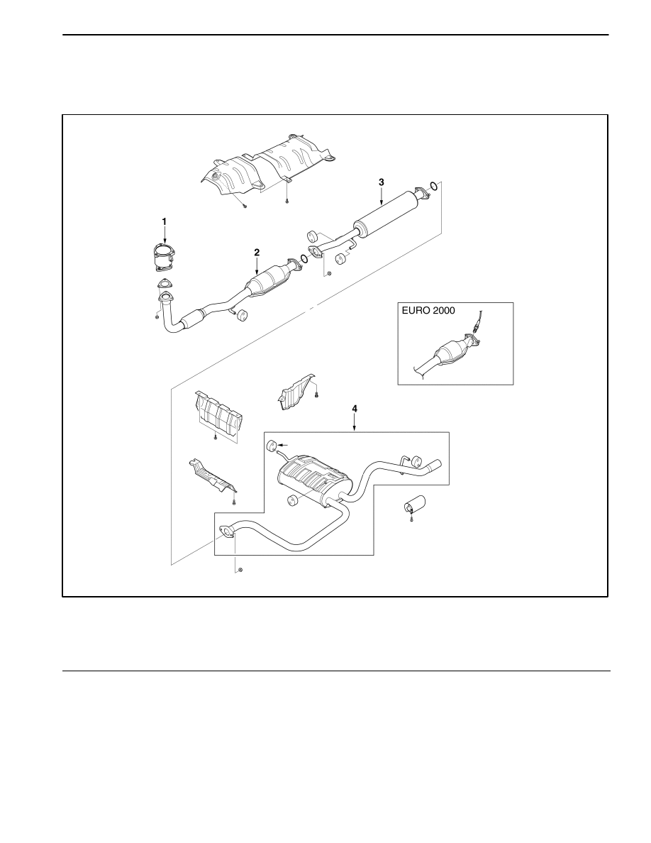
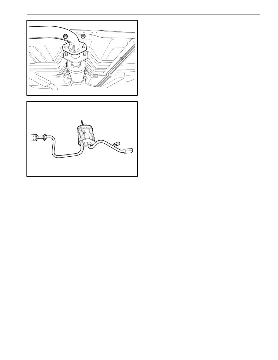
COMPONENT LOCATOR
EXHAUST SYSTEM
D12G4011
1 Pup-up Catalytic Converter
2 Front Exhaust Pipe/Catalytic Converter
Assembly
3 Front Muffler Pipe
4 Rear Muffler Pipe
1G – 4 ENGINE EXHAUST
DAEWOO M-150 BL2
REPAIR INSTRUCTIONS
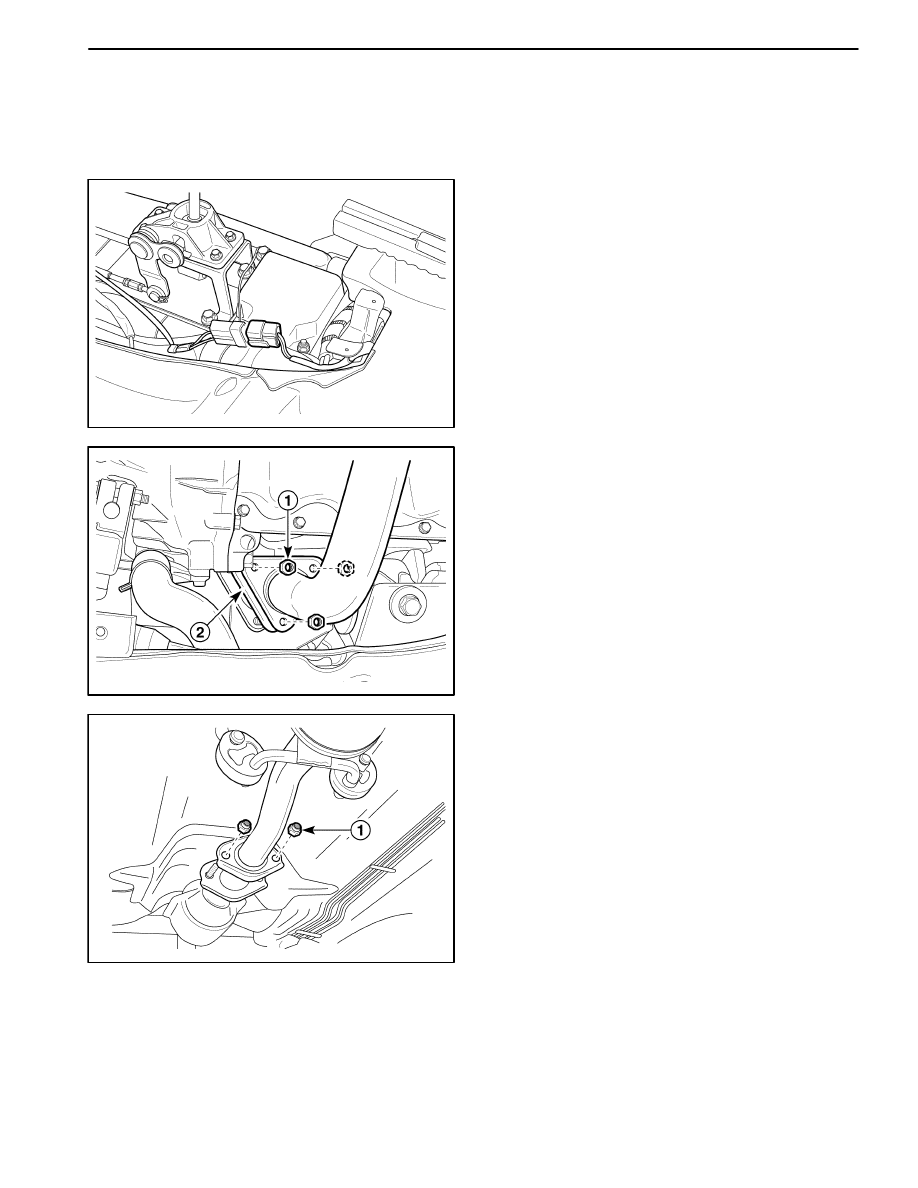
ON–VEHICLE SERVICE
MAA1G010
EXHAUST PIPE/CATALYTIC
CONVERTER
Caution : Make sure to confirm that the components
is cool. And do work.
Removal Procedure
1. Remove the floor console. Refer to Section 9G, Inte-
rior Trim, if equipped Heated Oxygen Sensor (HO2S).
2. Disconnect HO2S connector.
D102G501
3. Remove the front exhaust pipe from the exhaust
manifold or pup-up catalytic converter.
D
Remove the nuts (1).
D
Remove the gasket (2).
4. Check the gasket for damage or crack.
D102G502
5. Remove the front exhaust pipe from the front muffler
pipe.
D
Remove the nuts (1).
ENGINE EXHAUST 1G – 5
DAEWOO M-150 BL2
D102G503
6. Remove the front exhaust pipe and the catalytic con-
verter assembly.
a. Front exhaust pipe.
b. Catalytic converter.
7. Clean the sealing surfaces on the front exhaust pipe
flange and the exhaust manifold.
8. Check the exhaust pipe and the catalytic coverter for
holes, damage, open seams, or other deterioration
which could permit exhaust fumes to seep into the
passenger compartment.
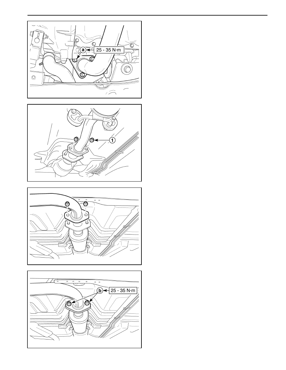
D12G504A
25–35 N
S
m
25–35 N
S
m
Installation Procedure
1. Using the nuts and the gasket, secure the front ex-
haust pipe and the catalytic converter assembly to
the exhaust manifold.
Tighten
Tighten the nuts to 25–35 N
S
m (18–25 lb-ft).
a. Front exhaust pipe nut.
2. Install the front exhaust pipe and the catalytic con-
verter assembly to the front muffler pipe flange. Use
the nuts to secure the front exhaust pipe and the cat-
alytic converter assembly.
Tighten
Tighten the nuts to 25–35 N
S
m (18–25 lb-ft).
b. Front muffler pipe nut.
Notice : Make sure not to contact the components with
the underbody.
3. Connect the Heated Oxygen Sensor (HO2S) connec-
tor.
4. Install the floor console. Refer to Section 9G, Interior
Trim.
D102G501
PUP-UP CATALITIC CONVERTER
Removal Procedure
1. Remove the front exhaust pipe from the pup-up cata-
litic converter.
D
Remove the nuts (1).
D
Remove the gasket (2).
2. Check the gasket for damage or leak.
1G – 6 ENGINE EXHAUST
DAEWOO M-150 BL2
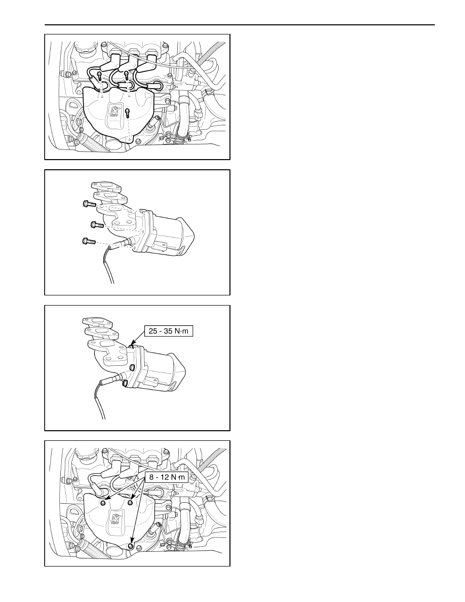
MAA1B010
3. Remove the air cleaner assembly. Refer to Section
1B, SOHC Engine Mechanical.
4. Disconnect Oxygen Sensor (O2S) connector.
5. Remove the exhaust manifold heat shield.
6. Remove the exhaust manifold. Refer to Section 1B,
SOHC Engine Mechanical.
MAA1B040
7. Remove pup-up catalytic convertor.
D
Remove the bolts.
MAA1B041
Installation Procedure
1. Install pup-up catalytic convertor to exhaust pipe.
Tighten
Tighten the bolts to 25–35 N
S
m (18–25 lb-ft).
MAA1B011
2. Install exhaust manifold. Refer to Section 1B, SOHC
Engine Mechanical.
Tighten
Tighten the bolts and nuts to 17–27 N
S
m (13–20 lb-ft).
Tighten the exhaust manifold heat shield bolts to
8–12 N
S
m (71–106 lb-in).
ENGINE EXHAUST 1G – 7
DAEWOO M-150 BL2
D12G504B
3. Install the front exhaust pipe to pup-up catalytic con-
vertor.
Tighten
Tighten the bolts to 25–35 N
S
m (18–25 lb-ft).
D102G502
FRONT MUFFLER
Removal Procedure
1. Remove the front exhaust pipe-to-front muffler nuts.
D
Remove the nuts (1).
MAA1G030
2. Remove the front muffler-to-rear muffler nuts.
3. Detach the front muffler from rubber hanger and re-
move the front muffler.
MAA1G031
Installation Procedure
1. Hang the front muffler to rubber hanger.
2. Install the front muffler-to-rear muffler nuts.
Tighten
Tighten the nuts to 25–35 N
S
m (18–25 lb-ft).
3. Install the exhaust pipe-to-front muffler nuts.
Tighten
Tighten the nuts to 25–35 N
S
m (18–25 lb-ft) (a).
1G – 8 ENGINE EXHAUST
DAEWOO M-150 BL2
MAA1G030
REAR MFFLER
Removal Procedure
1. Remove the front muffler-to rear muffler nuts.
Tighten
Tighten the nuts to 25–35 N
S
m (18–25 lb-ft).
2. Detach the rear muffler from the rubber hangers.
MAA1G040
3. Remove the rear muffler.
4. Installation should flow the removal procedure in re-
verse order.

ENGINE EXHAUST 1G – 9
DAEWOO M-150 BL2
SPECIFICATIONS
FASTENER TIGHTENING SPECIFICATIONS
Application
N
S
m
Lb-Ft
Lb-In
Front Exhaust Pipe-to-Front Muffler Pipe Nuts
25 – 35
18 – 25
–
Front Exhaust Pipe-to-Exhaust Manifold Nuts
25 – 35
18 – 25
–
Front Exhaust Pipe-to-Pup-up Catalytic Converter
25 – 35
18 – 25
–
Front Muffler-to-Rear Muffler nuts
25 – 35
18 – 25
–
Pup-up Catalytic Convertor-to-Exhaust Manifold Bolt
25 – 35
18 – 25
–
Muffler Clamp Nut
24 – 28
18 – 21
–
Catalytic Converter Heat Shield
8 – 12
–
71 – 106
Rear Muffler Heat Shield
8 – 12
–
71 – 106
Wyszukiwarka
Podobne podstrony:
ENGINE EXHAUST SECTION 1G 12
Engine Exhaust
Diesel engine, Akademia Morska -materiały mechaniczne, szkoła, Mega Szkoła, Szkoła moje
04 Engine
Mazda 6 (Mazda6) Engine Workshop Manual Mzr Cd (Rf Turbo)(3)
M31f1 Engine Controls 1 54
Engine Compartment 4 7
10 Engine Control System
Computer engine control
ARTICLE MAINT INSPECTION ENGINE
engineering projects
M31f4 Engine Controls 280 324
M31e1 Engine Electrical 1 18
75 Engine Hood and Doors
M31b1 SOHC Engine Mechanical
HEX?ficiency Exhaust
Chemistry for Environmental Engineering and Science
Swanwick Ancient Engines
więcej podobnych podstron