161
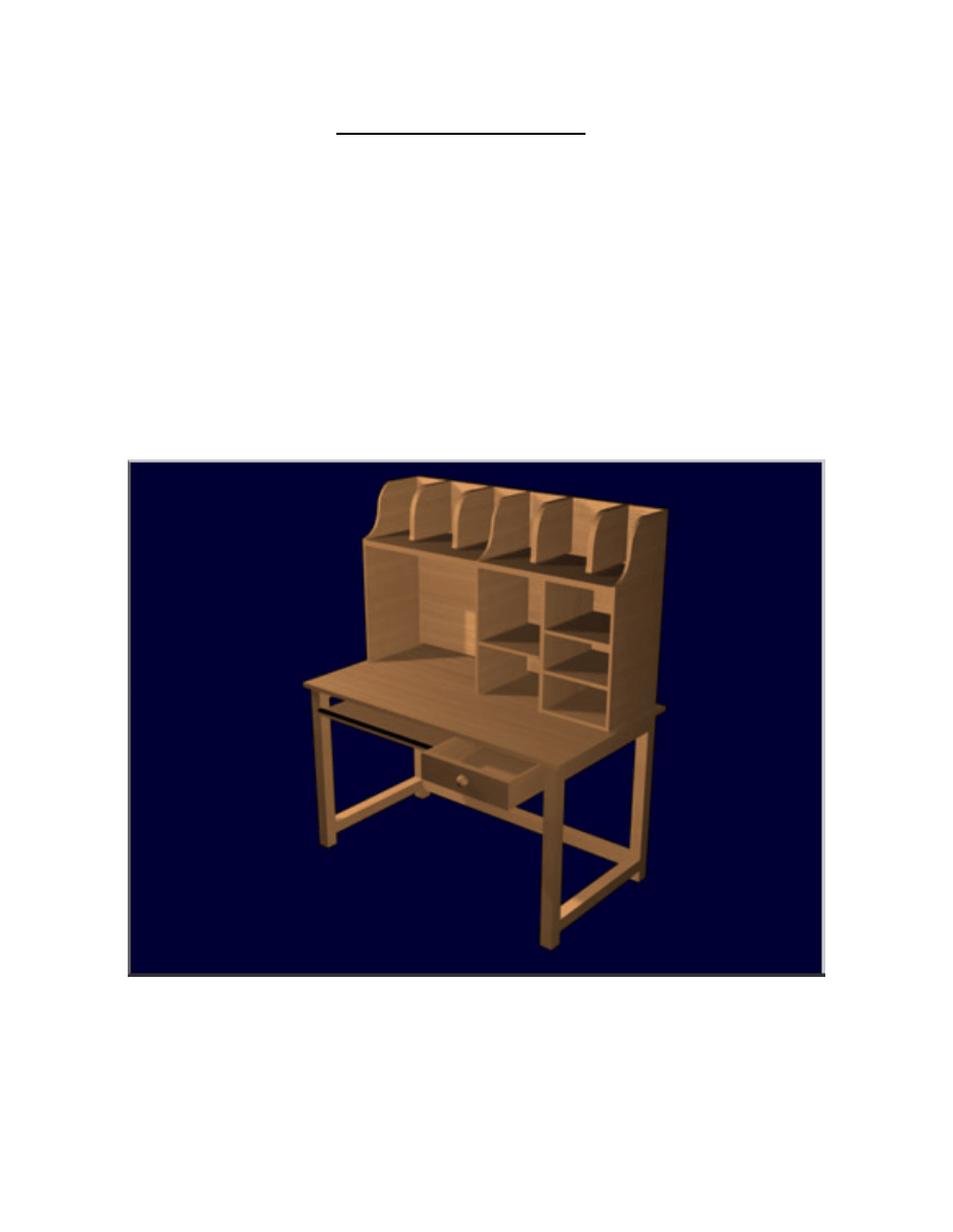
COMPUTER
WORKSTATION
Copyright 2004 Martian Auctions
726
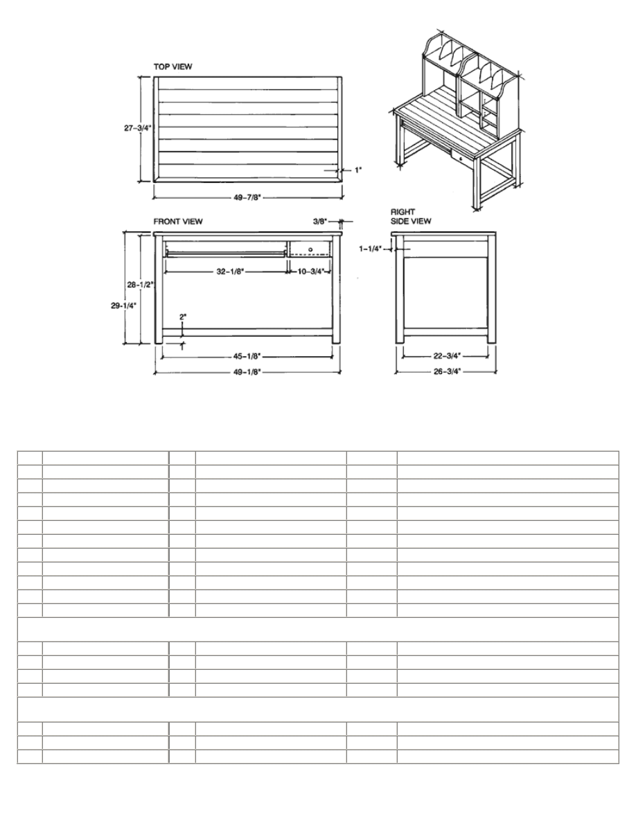
Computer Workstation Buying and Cutting List
Key Parts
Pcs. Size
Material Cut From (buy) *see Notes
A
Top
1
3/4 x 26-3/4 x 47-7/8" (OA)
Pine
4/8, 1 x 4
B
Edging, ends top
2
3/4 x 1 x 27-3/4"
Pine
All edging from 1/5, 1 x 6
C
Edging, front top
1
3/4 x 1 x 49-7/8"
Pine
"
D
Legs
4
2 x 2 x 28-1/2"
Pine
1/5, 8/4 x 6
E
Top rails, front and rear
2
3/4 x 1-1/2 x 47-1/8"
Pine
All rails from 1/7, 1 x 4
F
Top rails, ends
2
3/4 x 1-1/2 x 24-3/4"
Pine
"
G
Rear stretcher
1
1-3/4 x 1-5/8 x 47-1/8"
Pine
All stretchers cut from 1/7, 8/4 x 8" board
H End
stretchers
2 1-3/4
x 1-5/8 x 24-3/4"
Pine
"
I
Dividers
3
3/4 x 4-1/4 x 26-1/2"
Pine
1/8, 1 x 6
J
Cleat
1
3/4 x 1-1/2 x 22-3/4"
Pine
Scrap box
K
Drawer shelf
1
3/4 x 12-1/4 x 26-1/4"
Pine
1/5, 1 x 8
Drawer
L
Drawer sides
2
1/2 x 2-5/8 x 12-1/2"
Pine
1/5, 1 x 4
M
Drawer back
1
1/2 x 1-7/8 x 10-5/8"
Pine
1/1, 1 x 4
N
Drawer front
1
3/4 x 4-3/16 x 12-1/4"
Pine
1/18, 1 x 6
O
Drawer bottom
1
1/4 x 10-1/16 x 11-15/16"
Plywood
1 sq. ft.
Keyboard Platform
P
Keyboard platform
1
3/4 x 14-5/8 x 30-7/8"
Pine
1/5, 1 x 4
Q** Hand rest
1
3/4 x 2 x 30-7/8"
Pine
1/1, 1 x 4
R
Stop blocks
2
3/4 x 3/4 x 3-1/2"
Pine
1/18, 1 x 6
Copyright 2004 Martian Auctions
727

Procedure
Construction begins with the workstation table. Be aware that the dimensions used are standard, since the aim is to create a piece of
furniture that provides optimum comfort for the person working at it. The monitor and keyboard elevations are of primary
importance. You may want to evaluate the most comfortable heights for working at a computer and, should they vary from the
shown dimensions, make changes on the drawings so you can custom-build the table to suit your own needs.
You are advised to work with the dimensions given on the drawing, however, since these are in accord with accepted architectural
standards.
START WITH THE TABLE
1. Start by cutting the 1 x 4 stock for the top slightly longer than the top's finished length.
2. Check all edges for warp, cupping and square: Board edges must be perfectly true if you are to achieve almost-invisible
joints in edge-joined work. To be sure that yours will be, run all board edges through the jointer.
3. Next, lay out the boards on your worktable and arrange them so they produce the most pleasing grain appearance. At the
same time, make sure you flip the boards so that the annular rings in abutting boards alternate (i.e.: The rings of the third
board should be positioned the same as the rings of board number one, and, so on). Annular rings are alternated in edge-
joining to further minimize chance of warping or cupping.
4. When satisfied with board arrangement for the top, using a pencil, make marks where the biscuits are to go.
5. Using a plate joiner and the marks you just made, plough the biscuit grooves to suit no. 20 biscuits.
6. Assemble the table top using glue and no. 20 biscuits.
7. Use at least three bar clamps to hold the setup securely while the glue dries. Place one near each end and the third, centered
on the opposite side of the table top.
8. Allow clamped setup to dry for 24 hours.
9. The next day, remove clamps and scrape off any glue squeeze-out using a sharp cabinet scraper. Finish the smoothing step
by belt-sanding the complete top; first with 80-grit abrasive, then with 100-grit.
10. Finally lay out the top for exact width and length. Using either a table or circular saw, cut the ends to produce top's exact
length. Then, rip the top to its exact width on the table saw. Note that the top (at this point) is cut to the dimensions shown
in the drawing--without the edging strips in place on front and side edges. Set top aside.
11. Rip edging strips B and C to size and install them on the top using glue and 1-1/2 in. finishing nails. Use miter joints at the
corners and be sure to use glue in those joints. The next day, after the glue has dried, secure the miter joints by driving a
pair of opposing 1-1/4 in. brads through each mitered corner. Finally, set all nailheads slightly below the surface. Set top
aside.
Cabinetmaker's Tip: When gluing up a table top, professionals never use boards wider than 1 x 4 nominal. Be aware that wider
boards greatly increase the risk of warping and cupping as the wood dries, generally during the winter months or in a heated home.
12. Cut the remaining structural members for the table to size and length. Notice that the legs are a full 2-in. square. You may
be required to alter the leg dimensions, depending upon what your lumberyard has in stock. If you cannot get full 8/4 stock,
it may be necessary to trim the stock you have to create legs either 1-3/4 or 1-7/8 in. square.
Cabinetmaker's Tip: Do not cut any of the materials for either the keyboard platform or drawer until after your basic table is built
and assembled. At that time you can take actual dimensions, sizes, etc. for these members directly from the table. This will ensure
both perfect fit and minimal wasted materials.
13. Carefully lay out for the mortises in the legs. If available, use a bench top mortiser to bore the mortises in the legs. If your
shop lacks this useful tool, create the mortises by boring overlapping 1/2-in.-dia. holes and cleaning the holes square using
sharp chisels.
14. Lay out the stretchers (to legs) and make mating match marks where each stretcher meets a leg. (Note: Use marks that
won't confuse later like I, II, III and so on.) Then mark each piece for tenon to be cut so it will mate tightly with its mating
leg mortise. Carefully cut the tenons using a back saw; clean up tenons as necessary with a sharp wide chisel. Test-fit all
undercarriage pieces with tenons in their respective leg mortises. Do this testing dry, without glue, before proceeding with
final assembly.
Copyright 2004 Martian Auctions
728

15. Next, set up the table saw with dado head and rip fence so you can plough the grooves, which will receive the tabletop hold-
downs. These will be ploughed in the inside surfaces of the front and back rails.
16. Because it goes a lot faster with the parts disassembled, sand all parts smooth using a belt sander and 120-grit paper.
17. Assemble the table as shown in the drawing, using glue. Working quickly, locate the dowel positions on the legs and bore the
necessary holes so that the fully seated dowels will be inserted through the tenons and into the leg on the far side. Apply
glue to dowels before inserting them into their holes; tap dowels home with a wooden mallet.
18. Check the table setup for square using a framing square. When satisfied with squareness, secure the carcass by tacking
diagonal braces across opposing corners. Then clamp the setup so the joints will be immobile while glue sets.
19. Use appropriate-length bar clamps: You will need two with 5-ft. capacity and three with 30-in. capacity.
20. The next day, the top can be positioned on a worktable, bottom-side up, and the table undercarriage (also turned upside
down) located on it. Check with a ruler to make certain the top's ends are equally distant from the end stretcher plane, and
that the top's rear edge is flush at back. When the undercarriage is properly positioned, hold it that way with a couple of c-
clamps while you position and install the hold-downs with wood screws. When all is secured, remove the c-clamps and flip
the table right side up.
Cabinetmaker's Tip: Though it is a basic technique, make sure you protect the wood surfaces when clamping. If your clamps do not
have plastic shields, use scrap wood between clamp jaws and wood surface to prevent jaw marks from clamp pressure.
21. Cut parts I and K for the drawer compartment to size and install on the table using carpenter's glue and 1-1/4 in. screws (or
air-driven 1-1/2 in. nails). (see illustration)
22. Cut the parts for the drawer and sand all members smooth, working up to 120-grit paper before assembling the drawer.
Take time to study the drawing to be sure you understand how the drawer front is rabbeted; i.e., the drawer front should
conceal the compartment members (parts I in illustration).
23. Lay out and bore the hole for the drawer knob in the drawer front.
24. Insert drawer into its recess and position it in the closed position. Check the front to make sure that it fits, and conceals the
vertical members behind the front. Make any necessary adjustments.
25. To prevent the (short) drawer from falling out if pulled forward too vigorously, install the shaped 1/4-in. plywood stop as
shown. Bore a pilot hole through the plywood. Then, hold the stop in place with a 5/8-in. rh screw. Tighten the screw until
the stop can be rotated to stay in the vertical position. Finally, install the drawer and rotate the stop to the vertical (drawer
stop) position, and tighten the screw a tad more to ensure it remains vertical.
26. Next, go to work on the keyboard platform. Cut the boards for it and edge-join them using glue and no. 10 biscuits. As you
did for the tabletop, alternate the annular rings of abutting boards to minimize chance of warping. Apply clamp pressure and
leave the setup overnight.
27. Next, lay out and install the platform's slide hardware on table and platform sides. Install the keyboard platform's stop blocks
at the ends of the table-mounted slides. Note: Do not use glue on the stop blocks since you may have to reposition them in
the future.
28. Insert platform into the table.
29. Push platform to the closed position to make sure it is flush with table front; adjust stop blocks if it is not.
30. Cut the piece of lumber for the hand rest and shape it using a block plane and belt sander. When satisfied with its contour,
install it on the platform using glue and countersunk wood screws from below.
Except for its final sanding and the finishing steps, your table is now complete.
Optional: You may want to install furniture glides on the bottom surface of all legs to prevent (or, at least minimize) the table from
rocking should it eventually be placed on an uneven floor. If you do decide to add glides, buy the 3-prong type of at least 7/8-in. dia.
Building the Hutch Top
The hutch top for the Computer Workstation is easier to build than the desk. However, since the upper section of this project is in
prominent view, build and finish it with the same care, patience and precise workmanship that you used in building the table.
Copyright 2004 Martian Auctions
729

Build the hutch top in two sections; these are then joined for maximum rigidity after being installed on the desktop. By doing this, it's
possible to alter the design of one or both units to suit your equipment and taste.
The hutch size, overall, is determined by two factors:
(a) The left unit is sized to accommodate a 21-in. monitor and,
(b) The right hutch will store computer-related paraphernalia such as CDs, floppies, notepads, etc.
As mentioned earlier, hutch sizes can be altered. If your monitor varies from 21 in. or if you want to customize the unit to adapt it for
other uses or storage, you may take some liberties in its design.
Before You Begin
1. Start by cutting the boards for the legs (sides) to length, but cut them slightly longer than the finished sides will be. (In this
case, that means about 30 in.) Note that each side consists of two lengths of 1 x 6 and one length 1 x 4. This will give you
four stacks of three boards each which, when joined, will be both longer and wider than the required 13 in.
2. Lay out each set of three boards to achieve the best grain match for each leg and, at the same time, try to alternate annular
rings on abutting boards to minimize chance of warping or cupping. When satisfied with arrangement, lightly draw a
cabinetmaker's triangle across the face of each of each setup: This way each set of three boards can be quickly returned to
your preferred layout of them.
3. Next, joint all edges in the four piles; check the mating edges as you go (an easy step because you have the cabinetmaker's
triangle for reference) to ensure that joints will be tight and neatly matched when the boards are joined.
4. Align the first set of three boards for the first leg and carefully mark biscuit locations. Important: make sure you do not
position a biscuit in the top portion of each leg area, which is shaped later; you do not want the shaping to expose a biscuit
in the edge. Plough the mortises to receive the no. 20 biscuits. Then, making certain you keep the three boards together as a
set, put them aside on the work bench while you repeat this procedure for the following three sides (legs).
5. Start by gluing-up the boards for the 13-in.-wide "legs" or sides. Refer to your cabinetmaker's triangle to quickly return the
boards to the preferred grain layout you selected earlier. Position each set of boards as you work. For legs glue-up, you will
need at least 12 bar clamps, 3 per setup. Have these, as well as the glue, a glue brush and biscuits at hand before starting
the assembly step.
6. Apply glue to mating board edges and biscuits and assemble the first three boards. Ends should be aligned and boards
should lie flat against bars (i.e., no bow) when clamp pressure is applied. To minimize the chance of cupping or bowing
occurring when clamp pressure is applied, use a pair of clamps on one side of the boards, positioned about 4 in. from each
end and one clamp at center on the opposite side. Put the clamped setup aside and allow to dry for 24 hours. Repeat
assembly procedure for the remaining three sides.
7. The next day, remove the clamps and trim the four legs so all four are exactly the same size--13 in. wide by 29 in. long.
Crosscut all boards to length on the radial arm saw, using a stop block to ensure all are the same length. Then, on the table
saw, rip boards to width, taking some stock off both front and back edges (this will remove any edges dented during
handling, clamping, etc.).
8. Tack two of the legs together for the right hutch (R1) and two for the left (L1) after aligning each pair so all edges are flush.
Hold them that way for the shaping which follows, using a half-dozen or so 1-1/4 in. brads driven flush.
9. Refer to the drawing of the shaped top, shown on 1-in. squares in the drawing, to make a template of 1/4-in. hardboard or
plywood. When satisfied with template's layout, cut it out using saber or scroll saw. Sand the cut edge smooth.
10. Use this template to trace the shaped tops to the two pairs of legs you previously tacked together. Cut out the shape using
saber or scroll saw.
11. Sand the scroll shapes smooth using either a spindle or drum sander chucked in the drill press.
Note: Since the dividers used on the fixed top shelves repeat the symmetry of the scroll shape used on the legs, set the scroll
template aside for reuse later. When you come to make the dividers, you can simply refer to the drawing for shape then re-cut the
template for use as a divider template.
12. Repeat the board layout and edge-joining steps to make all the shelves for your two units both finished and adjustable. All of
these should be slightly oversize overall when they're glued-up; they will be trimmed to fit exactly after hutch units are
assembled.
Copyright 2004 Martian Auctions
730

Cabinetmaker's Tip: You can edge-join the boards for both hutch tops in a single session as long as you use identifying marks.
Make marks lightly with a soft pencil on the back edges of boards. (Use R for right cabinet; L for left.)
Cabinetmaker's Tip: Since you have cut your boards so that each side (leg) setup will be slightly oversize when assembled, there is
no need to place scrap blocks between the clamp faces and wood (to prevent marred edges). Board lengths and widths will be
trimmed in the next step, and clamp marks will be cut off.
Note: The following instructions take you through the steps for building the left hutch, the one that houses the monitor. The same
construction steps are used to build the right hutch except for the addition of the adjustable shelves. The required steps for installing
these are explained below.
13. Before laying out the shelf dadoes on the legs for the left hutch, measure the monitor that will be used on your workstation.
Everything begins with that dimension. Make sure that the distance from leg bottom edge to bottom plane of dado provides
adequate clearance for your monitor's height. (Your monitor size determines the fixed shelf location in the left hutch.) You
will have to alter the right hutch dimensions so the two fixed shelves remain in line. Also, if the left hutch width dimensions
are altered, the right hutch must be adjusted a corresponding measurement so that the hutch sits on the table with a 1-in.
setback from table edge, left and right.
14. Since the legs (L1) for the unit have already been sized (step 7), you can now lay out the dadoes to receive the fixed shelf
(L2).
15. The dadoes for the fixed shelf should be perfect mirror images in left and right legs, so make sure the legs will be exactly
opposite each other in the finished cabinet. Here's how to do it:
16. Position the two legs on your worktable back-edge to back-edge and clamp them so they cannot move.
17. Lay out for the dado to be rabbeted in both legs and plough it using a 3/4-in. straight router cutter set to a depth of 3/8-in.
Cabinetmaker's Tip: On work such as this, where there is no room for error, you must always use a guide when ploughing with a
router. Be certain you clamp on a guide which puts the router cutter right on the mark. Hold the router shoe firmly against the guide
as you cut and, to further minimize chance of a cutting error, push the router with a slow, easy-to-control feed rate. To be extra safe,
you can clamp a guide so both sides of the router shoe will be guided and to eliminate any possibility of the router "walking" off the
cutting mark. If you opt to cut your dadoes using the table saw, make certain you use a miter gauge hold-down to prevent lateral
movement of the work piece as the saw blade does its cutting. You must use a stop to position each workpiece accurately before it is
pushed into the spinning blade. This ensures that the dadoes in both legs are positioned the exact distance from the leg end. If you
have never done repetitive crosscutting on the table saw, discuss this step with your instructor before proceeding.
18. Next, insert a 3/8-in. rabbet cutter in your router and plough the blind rabbets in the back edges of both legs to receive the
back (L3).
19. Assemble the two legs, fixed shelf and back without glue so you can check all for fit; use small (1-1/4 in.) brads if necessary
to temporarily hold the parts together so you can do your visual check. Now lay out for the 5/16-in.-wide dadoes that will
hold the dividers used in the fixed top shelf. Mark both the shelf and the back at this time.
20. When satisfied with fit, disassemble the hutch and abut the fixed shelf and back with the marks for the dadoes lined up.
Clamp the boards together so they will not move and, starting at the back edge, rout the dadoes across, stopping shy of the
front edge in order to create the blind dado as shown in the drawing. After routing, the front round corner can quickly be
made square (to receive the divider) using a sharp 1/4-in.-wide chisel.
21. Reassemble the hutch using glue and fasteners of choice. Note: Because of their superior holding ability, you can use
pneumatically driven 1-1/2 in. nails to join parts here. These are driven slightly below the surface and the indents can be
filled with Wood Filler. Or, if preferred, 1-1/2 in. fh wood screws which are then covered with dowel plugs. If you opt for the
latter, remember that you must lay out for the screw pilot holes - for body, shank and counterbore - before you start the
assembly step.
22. With left hutch complete, stand it upright on the workstation table, flush at back and with approximately 1-in. setback from
the left table edge. Then, measure the distance from the outside plane of the right leg to the same width setback at the right
table edge. This measurement is the outside (i.e., overall) width dimension of your right-hand hutch. As stated earlier, this
measurement may differ from our drawing depending upon how the left-hand hutch is sized. If there is variance with the
plan drawing, now is the time to calculate all dimensional changes and to mark them on your drawing--before starting any
work on your project wood for the right hutch.
23. The right-hand hutch is constructed using the same procedure as for the left--except for two steps you must take before
assembly: a) The holes for the adjustable shelves should be laid out and bored; you won't be able to fit a drill between legs
Copyright 2004 Martian Auctions
731

R1 and R4 after the unit is assembled. And, b) the dado for the middle leg (R4) must be routed in the underside of fixed
shelf. Attempting this after assembly could result in damage to shelf legs. When the right unit is complete, set it atop the
table abutting the left unit. Recheck both the left and right setbacks, the tabletop reveal, to make sure the left and right legs
are equally distant from table edge. If the distance varies, even slightly, move units left or right to achieve that goal.
24. When satisfied with their location, position a pair of handscrew clamps on the legs at center to hold the two units together.
With a pencil, lightly mark the front corner of both the left and right (outside) legs and make match marks on tabletop. Next,
carefully locate the points and make marks on both the tabletop and the legs to indicate where you must bore the holes to
receive the dowels, which serve as keepers when the unit is assembled. Note that this is back about 1 in. from front edge of
vertical and centered on leg width.
25. With handscrew clamps still in place, lay out for the Teenuts
®
to be installed on the middle legs. The fastener's locations
aren't critical but, for the sake of craftsmanship, they should look precisely placed. Then bore the needed holes.
26. From the left side (i.e., the monitor's hutch), start by boring the large dia. holes to suit the Teenut, to 1/2-in. depth. Then
insert a 5/16-in. bit and bore through at center of each counterbore to receive the machine screw.
27. Then switch to a countersink and, in the right hutch, countersink all four holes to receive the machine screw head.
28. Tap the Teenuts in place and secure them with the machine screws.
29. With the hutch unit still aligned on the table, position the mending plates on the three legs; one on each outside leg and the
third on the center leg. Mark the four screw hole locations for each plate. Bore all screw pilot holes but do not install the
mending plates as yet.
30. Carefully tilt the hutch back until it is fully supported and resting on its back. Next, bore the 3/8-in.-dia. holes in outside legs
and the table top to receive the keeper dowels. Then, glue the dowels into the legs so just about 3/4-in. of dowel protrudes.
Glue is used in the one side only so the hutch can be lifted off whenever necessary (i.e., for a move).
31. Wait one day, to make certain dowels are permanently affixed into the legs, then, bring the hutch to the upright position and
insert the dowels into the mating holes in the table top. Now you can install the mending plates using the screw holes you
bored earlier.
32. Your Computer Workstation is now complete. We also give instructions for an optional box which can be used to hold CDs
close at hand. You may, however, prefer to custom design a box to suit the "extras" you frequently work with. In this case,
the box shown here is a good starting point for your box.
Note: Leave your workstation assembled until you have completed constructing all the peripheral parts (CD holder, dividers, etc.),
because you want to be able to test fit these pieces before finishing the table. When satisfied all parts fit as they should, you can
disassemble the hutch and table to simplify the finishing step. Be sure to save all of the hardware and fasteners in a covered
container so you won't have to hunt for them when it is time to reassemble your workstation.
Dividers for Top Shelves
To ensure the wood in the dividers matching the wood used in the workstation, we planed 3/4-in. stock from the same
pile to 1/2-in. thickness, then created tenons on the bottom and back edges (see below). You could use 1/4-in. plywood
here and save a little work, but because of the exposed ply edges, the finished look will not be nearly as handsome.
Since the table saw is used to remove a scant amount of material from the divider stock to create the tenons, read the
Cabinetmaker's Tips below to learn the safe way to do this.
Here are the steps for making the dividers:
1. Cut the 1/2-in. stock to the divider size given in cutting list.
2. Next, to work production-fashion, align the edges of the four pieces. Then, while holding them fast, drive three 1-in. brads
through the pile.
3. Using your previously made pattern, trace the divider's scroll shape onto the top work piece.
4. Cut all four at one time using the bandsaw.
Copyright 2004 Martian Auctions
732

5. Sand all edges smooth using the stationary belt sander along the straight edges and the spindle sander for the scroll shape.
Lacking a spindle sander, chuck a sanding drum in either portable drill or drill press.
6. Separate the pile, remove and discard nails and set dividers aside.
7. Set up the table saw so you can safely remove about 1/8-in. from both sides of each divider, along the bottom and back
edges. See Cabinetmaker's Tips, below. Note: The exact thickness to remove will be determined by the actual thickness of
your stock and the width of the dadoes ploughed in shelf and back. The tenons you create on the dividers must fit freely in
those dadoes.
Cabinetmaker's Tips: Never lay out a shape on your project wood; always make a template or pattern first. You can use either 1/4-
in. hardboard or plywood--or even sturdy cardboard. Lay the shape out on your template material following the pattern given in the
plan. Cut it out using saber or scroll saw (or razor knife if template is cardboard). File and sand all cut wooden edges to remove
"whiskers" before using the pattern to transfer the shape to your project wood.
When a small, identical amount of wood must be removed from a number of surfaces, the most accurate technique is to
set up the saw so that the waste is between the blade and fence. That is the case here, where approximately 1/8-in. is
removed from both sides of the bottom and back edges. This creates tenons to fit in the dadoes provided for them.
However, whenever the saw blade is this close to the fence, there is very real risk of the blade engaging the metal
fence: this can be dangerous at worst, blade damaging at best.
For safety, always install and work with a wooden auxiliary fence whenever you are faced with doing this type of
cutting on the table saw. In order to cut the dadoes on the 7 x 9-in. dividers, make an auxiliary fence from a length of 1
x 6." Line the board up with the rip fence and with an awl, make prick marks through the holes on your fence. Use
3/16-in. dia. fh machine screws and wingnuts to secure the auxiliary fence to rip fence. Caution: Make certain the screw
heads are perfectly flush with the wood's surface when the board is secured tight against the fence by the wingnuts: the
work piece must be able to slide past without interference when you make your cuts.
If you have never installed and worked with an auxiliary fence on a table saw, make sure you discuss the setup with
your teacher before its installation and use.
The CD Box
The box shown in the plan was built to house a commercially available plastic CD box (
see Materials list)
. Slotted
plastic sheets are created for CD storage. Many mail order woodworker's supply houses offer these. They are available
in both end and center CD holder configurations and are installed using polyurethane glue. If you want to build a
custom CD box, make sure the box (i.e., its overall dimensions) fits in the right-hand hutch.
Making the Box
1. After cutting all parts to sizes shown in drawing, sand them smooth starting with 100-grit and finishing with 120-grit abrasive
paper.
2. The corners are mitered and held secure with no.0 biscuits. Or, if preferred, you can use splines. Here, simply pass the miter
faces through the table saw blade to a depth of about 3/4-in. and join the mitered corners using 1-1/2 in.-wide splines. If
you opt for the latter technique, you may want to cut thin strips of molding to glue on the front edge to conceal the splined
corners.
3. The back is of 1/4-in. cabinet grade plywood; install it using glue and 1-in. brads.
Copyright 2004 Martian Auctions
733
Wyszukiwarka
Podobne podstrony:
Desk Computer Workstation
Computerspieler Jargon
268257 Introduction to Computer Systems Worksheet 1 Answer sheet Unit 2
cloud computing1
COMPUTER
Mitre Saw Workstation
Pancharatnam A Study on the Computer Aided Acoustic Analysis of an Auditorium (CATT)
03 Bajor Krakowiak Cloud computing
Computer engine control
HP Computer Setup
Convert Computer ATX Power Supply to Lab Power Supply
Computer Systems Worksheet 1 Unit 2
Schools should provide computers for students to use for all their school subjects
Kluwer Digital Computer Arithmetic Datapath Design Using Verilog HDL
NIST Cloud Computing Synopsis and Recommendations sp800 146
Lecture 01 02 03 Computer Unix
LEVELING SYSTEM COMPUTER
więcej podobnych podstron