INSTRUCTION MANUAL
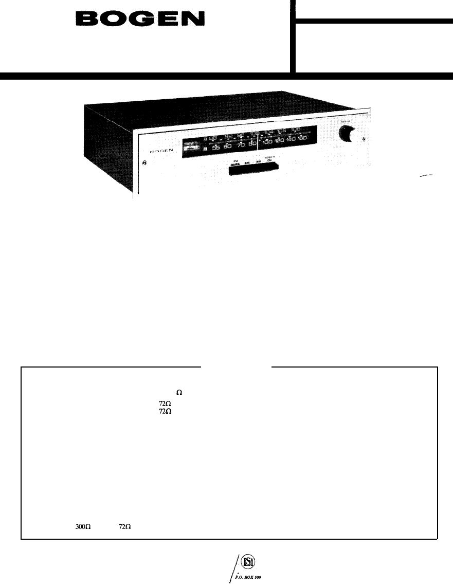
MODEL TP160
AM/FM TUNER
OPERATING INSTRUCTIONS
POWER
Depress POWER ON button to turn on tuner. Turn off
tuner by depressing button again to release it to the out
position.
AM
RECEPTION
Depress AM button. Turn TUNING knob until pointer
indicates desired station on AM (bottom) dial. Adjust TUN-
ING knob until needle on tuning meter shows maximum
deflection to right.
FM RECEPTION
Depress FM and FM MUTE buttons. Turn TUNING
knob until pointer indicates desired station on FM (top)
dial. Carefully adjust TUNING knob until needle on tuning
meter is at the center of the tuning dial, exactly on the
circle above the letters “FM”.
NOTE
Muting removes the annoying noise between FM
stations. The muting circuitry may prevent the
receiver from distinguishing a very weak signal
from interstation noise. To tune in very weak
stations, defeat the mute circuit by releasing
the FM MUTE switch to the out position.
SPECIFICATIONS
FM TUNER SECTION
TUNING RANGE: 87.5 MHz to 108.5 MHz @ 3 0 0
QUIETING SENSITIVITY: 1 . 5 µ V for 30 db @
0.5µV for 20 db @
HARMONIC DISTORTION: 0.3% at 100% modulation.
FREQUENCY RESPONSE: 20-20,000 Hz fldb (after de-emphasis).
AM TUNER SECTION
TUNING RANGE: 530 kHz to 1620 kHz.
LOOP SENSITIVITY: 2µV @ 6db S/N and 60% modulation.
ALTERNATE CHANNEL SELECTIVITY: (±l0 kHz) 40 db.
HARMONIC DISTORTION: Less than 1% @ SO% modulation
HUM AND NOISE LEVEL: 70 db below 100% modulation.
MISCELLANEOUS
ALTERNATE CHANNEL SELECTIVITY: 60 db. LHFM
DETECTOR BANDWIDTH: 900 kHz.
CAPTURE RATIO: 1.9 db.
IMAGE REJECTION: 60 db.
I.F. REJECTION: 85
db.
CROSS MODULATION REJECTION: 80
db.
ANTENNA:
balanced;
unbalanced or built-in line.
AUDIO OUTPUT: Adjustable (rear panel), 0-1.2V
OPERATING CONTROLS: Selector (Power, AM, FM, FM
Mute), Tuning.
POWER CONSUMPTION: 60W @ 120 vac, 6OHz
OVERALL DIMENSIONS: 14-l/2” W x 3-3/4” H x 12” D
RACK INTERIOR DIMENSIONS: 14” W x 3-l/4” H x 11” D
WEIGHT: 9-l/2 Ibs.
PRlNTED IN U.S.A.
10-70A
LEAR SIEGLER, INC.
BOGEN DlVlSION
PARAMUS, N. J. 07652
54-5516-01
INSTALLATION INSTRUCTIONS
UNPACKING
NOTE
This paragraph does not apply to tuners shipped
as a part of a Bogen Centralized School Sound Sys-
tern console or rack.
If the Model TP160 AM/FM Tuner is not part of a Bogen
Centralized School Sound System console or rack, care-
fully unpack the carton and inspect the unit for damage.
If a unit shipped to you proves to be damaged, make an
immediate claim with the shipping carrier. If the unit was
picked up directly from a dealer or distributor, make any
damage claim directly to the seller without delay.
RACK INSTALLATION
NOTE
This paragraph applies only to tuners which will
be installed in a 19”equipment rack.
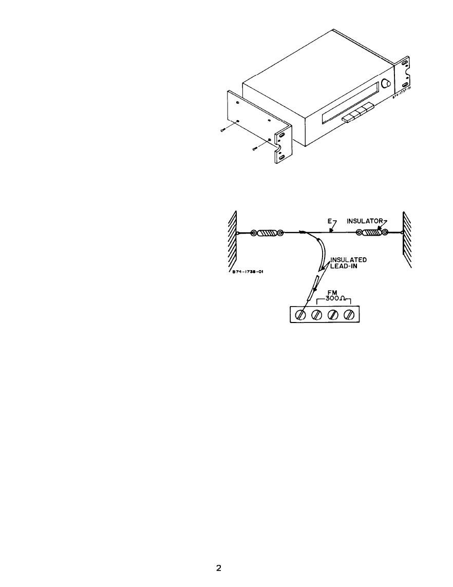
The Model TP160 may be installed in a standard 19” equip-
ment rack by using Model RPK31 rack mounting brackets.
Remove the four screws securing the side of the cover.
Do not remove the cover. Install the brackets as shown
in figure 1, securing them to the tuner with the four screws
supplied with the brackets. Each bracket has two elongated
holes on three-inch centers for fastening to a standard 19”
equipment rack.
Figure 1 - Rack Mounting With Model RPK-31 Brackets
HI-Z ANTENNA WIR
AM GND
Figure 2 - Connecting AM Antenna
CONNECTING AM ANTENNA
An external antenna must be installed on any Model
TP160 which will be used to receive AM broadcasts. Con-
nect the antenna as shown in figure 2.
Connecting
To External TV Antenna
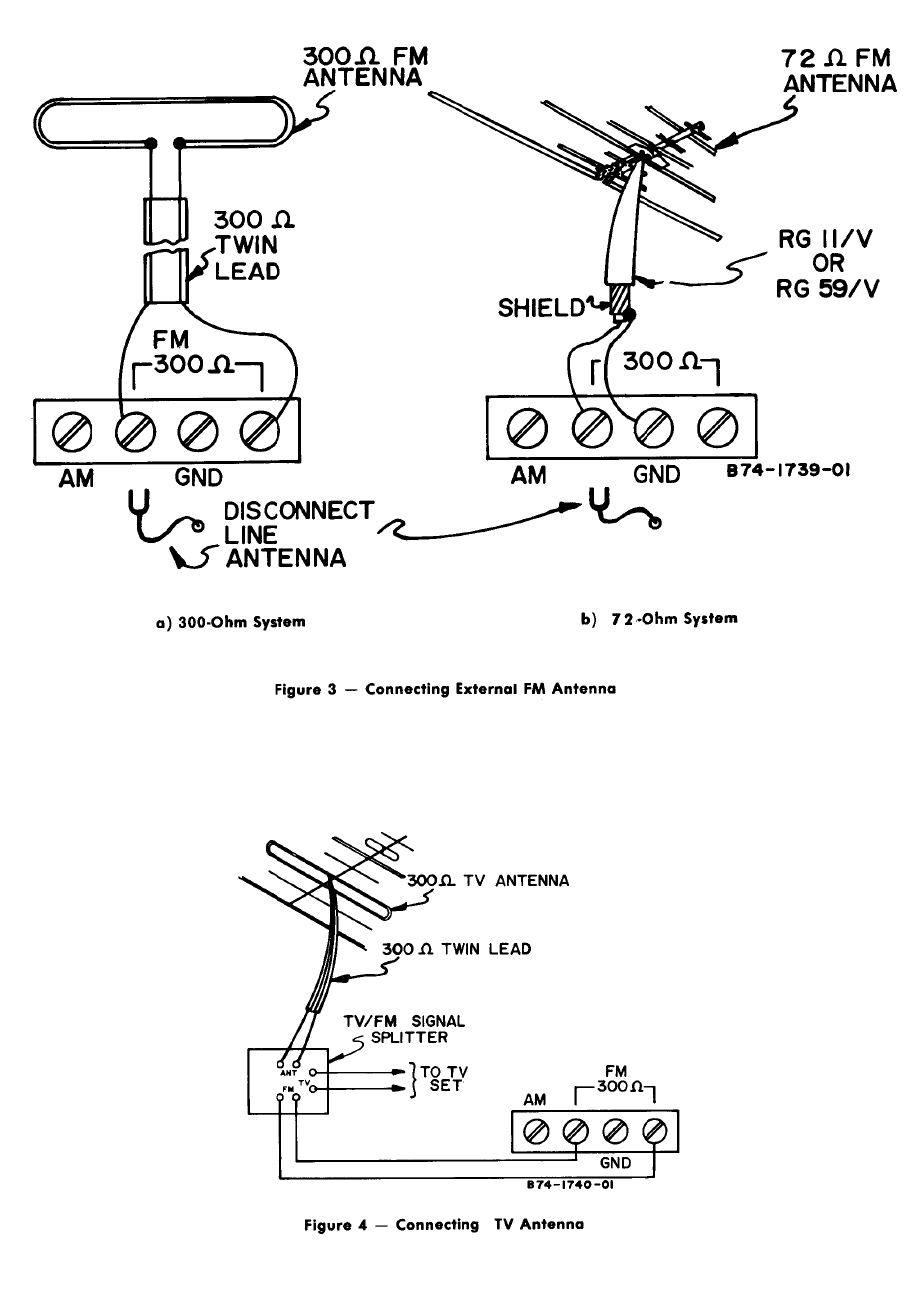
CONNECTING EXTERNAL FM ANTENNA
IMPORTANT
Always disconnect the FM Line Antenna
when using an external FM antenna.
The Model TP160 has an internal FM Line Antenna which
may be used for receiving FM broadcasts. For improved
reception, particularly in weak signal areas or for tuners
mounted in consoles or racks, installation of an outdoor FM
or “T” antenna is necessary. If you are installing a standard
300-ohm antenna system, connect the twin-lead transmission
line as shown in figure 3a. If conditions require use of a
coaxial transmission line, such as RG-11/U or RG-59/U,
connect the cable as shown in figure 3b. Coaxial cable must
be used when the transmission line is run in conduit.
For optimum performance, a separate FM antenna is rec-
ommended. If a TV antenna must be used for both FM and
TV reception, install an FM signal splitter at the end of the
transmission line, as shown in figure 4.
LEVEL CONTROL
Model TP160 AM/FM tuners shipped with Bogen Cen-
tralized School Sound System consoles or racks have the
LEVEL control preset to the proper output for the booster
amplifier. Tuners shipped separately have the LEVEL con-
trol set for maximum output, which is 1.2 volts.
To decrease the audio output from the tuner, turn the
LEVEL control counterclockwise. To increase the audio
output, turn the LEVEL control clockwise.
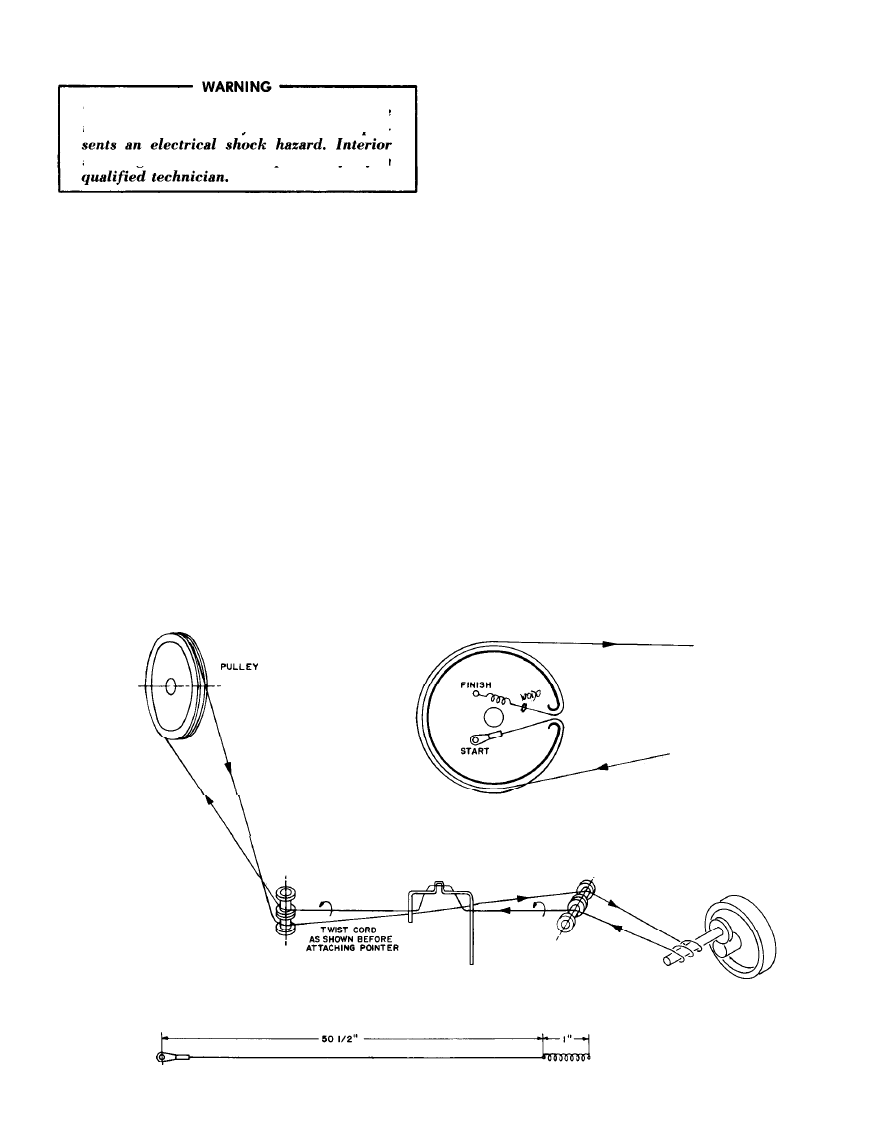
MAINTENANCE
There are no user serviceable parts inside
the unit and removal of the dust cover pre-
servicing should be attempted only by a
BOGEN SERVICE
We are interested in your Bogen tuner for as long as you
have it. If trouble ever develops with your unit, please do
not hesitate to ask our advice or assistance. Write to Ser-
vice Department, Bogen Division, Lear Siegler, Inc., P.O.
Box 500, Paramus, New Jersey 07652.
When communicating with us, give the model number
and serial number of your unit. Describe the difficulty
encountered and the effects each operating control has
upon the trouble symptoms. Include details on electrical con-
nections to associated equipment, and list such equipment.
When we receive this information, we will send you service
information if the trouble appears to be simple. If the trouble
requires servicing, we will send you the name and address
of the nearest Bogen authorized service agency to which you
can send your unit for repairs.
When shipping your unit, pack it carefully using the
original shipping carton, or a similar container and filler
material, to prevent damage in transit. Send the unit, fully
insured and prepaid, via railway express or United Parcel.
Do not ship via parcel post unless so instructed.
DIAL CORD RESTRINGING. Refer to figure 5 and proceed
as follows:
a) Remove front panel by pulling off TUNING knob and
removing two Phillips-head screws.
b) Connect dial cord at drum hook marked START in
diagram.
c) String dial around nylon pulleys and tuning shafe to
drum hook marked FINISH in diagram. Make certain cord
winds around tuning shaft from rear toward front, as shown.
d) Attach end of cord with tension spring, making certain
that spring applies enough pressure to prevent cord from
slipping.
e) Tune in a known station and attach dial pointer at proper
position. Before securing pointer, twist cord as shown in
diagram so cord will exert a slight pressure toward panel
bracket and away from dial glass.
REPLACING DIAL LAMP. Remove front panel as described
in step a), above, and replace lamp with 6.3V No. 12 bulb
(Bogen Part 94-0175-01).
REPLACEMENT PARTS
Most components used in the Model TP160 are avail-
able through all reputable parts jobbers. The parts listed
here are available from Bogen distributors, service agencies
or directly from the factory.
When ordering parts from Bogen, specify the part num-
ber and description, as listed below. Also give the Model
TP160 and the Series designation, which is a letter followed
by numbers stamped or screened on rear of the chassis.
When ordering a part for the PC Board, also give the PC
Board component number, which is 45-9764-01.
P U L L E Y
(SIDE
V I E W
)
.
POINTER
(FRONT VIEW)
C74--1744
* PROPER LENGTH WHEN SPRING IS STRETCHED TO I’:
Figure 5 - Dial Stringing Diagram
4
Ref. No. Part No. Description Ref. No. Part No. Description
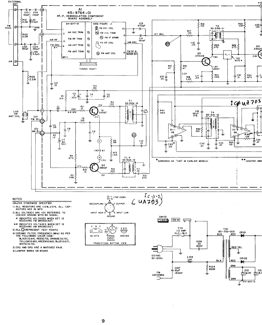
Al
45-9764-01
RF, IF Component Board Assy,
Complete
79-005-044
Capacitor, Electrolytic, 2µF, 25 V
79-209-001
Capacitor, 5pF, 500 V
79-008-057
Capacitor’50 µ F, 50 V
78-221-121
Capacitor, 470pF
78-221-116
Capacitor, 180pF
79-005-049
Capacitor, 25 µF, 35 V
78-221-113
Capacitor, 1OOpF
78-250-005
Capacitor, .06µ F, 50 V
78-201-099
Capacitor, 6.8pF, 5%
T3 96-5153-01
Transformer, 2nd AM IF
T4 965157-01
Transformer, FM IF
T5 96-5151-01
Transformer, FM Discriminator
c 3
C6
c 7
Cl3
Cl4
c25
C26
C30
c31
C35,36
c37
C40
Chassis Electrical Parts
ClOl-Cl04
78-201-115 Capacitor, 15OpF, 500 V
Cl07 78-200-100
Capacitor, 15pF, 1400 V
Cl08 79-005-062 Capacitor, Electrolytic,
Cl09
79-005-054
5 0 0 µ F , 50V
Capacitor, Electrolytic,
(Same as C26)
(Same as C13)
Capacitor, Electrolytic,
25µF, 25V
Cl10
79-005-039
7 0 0 µ F, 35 V
Capacitor, Electrolytic,
79-005-049
c41
C46
CR1,4
CR2,3
FL-l, 2
79-005-055
Capacitor, Electrolytic, 4µF, 50 V
96-5093-02
96-5093-01
78-959-001
(Same as C3)
Diode, lN541
Diode, lN542, Matched Pair
Ceramic Filter, FM IF (Specify
Color Code)
FL-3 95-5158-01
IC-1 96-5238-02
IC-2 96523801
Ll 95-5146-01
MPl 94-1277-01
Q1, 2
96-5221-01
Q3,4
96-5235-01
Q5
96-5237-01
Q6,7
96-5213-01
R90
77-001-691
Tl 95-5156-01
T2 95-5152-01
Mechanical Filter, 455 KHz
Integrated Circuit, 1st FM IF .
Integrated Circuit, 2nd FM IF
Coil, Choke, 56µ H
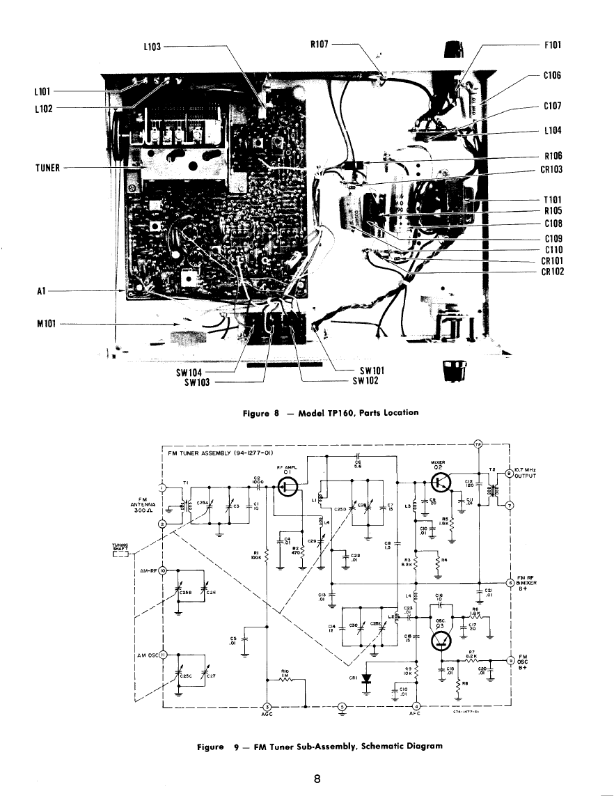
FM Tuner Assembly
Transistor, 2N5127
Transistor, 2N5126
Transistor, BC147B
Transistor, 2N5089
Control, Mute Adj., 47 K
Transformer, AM Oscillator
Transformer, 1st AM IF
CRlOl, 102 96-5109-01
CR103 96-5248-04
1101,102 94-0175-01
LlOl, 102 95-5148-01
L103
95-5159-01
L104 95-5015-01
Ml01 94-1309-01
R107 77-001-467
SW102-104
81-004-053
SW101 81-003-049
TlOl
83-750-000
1 0 0 0 µ F , 15V
Diode, lOOmA, 150 PIV
Diode, Zener, 12 V, 1 W
Lamp, Dial
Coil, RF Choke, 3.9 µ H
Coil, AM Antenna
Coil, RF Choke, 1µ H
Meter, Tuning
Control, LEVEL
Assembly, Pushbutton Switch
Switch, SPST, 3 A, with Cover
Transformer, Power
Mechanical Parts
-
12-4503-01
Dial Cord
-
12-4165-01
Dial Glass
-
02-9003-08 Dial Spring
-
22-5234-01 Cover
-
14-9064-01 Foot, Cover
-
03-0629-02 Knob, Tuning
ALIGNMENT
The following instruments (or equivalent) are required
for a complete alignment of the receiver.
DC VTVM, RCA WV98-C
AC VTVM, HP 400D
AM Signal Generator, Measurements Corp 65-B
FM Sweep Generator, Measurements Corp 88 or Boonton
Radio Corp 202H
AM Alignment
To completely align the AM section, start with the last
AM IF transformer and work back toward the antenna. In
order to limit the effect of the AGC circuit, continually
reduce the generator signal level to the minimum required
for an output indication. Make the adjustments listed in Table
I. See figure 6 for location of alignment adjustments.
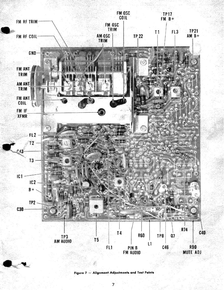
FM Alignment
To align the FM section, follow the procedure given in
Table II. See figure 7 for location of adjustments.
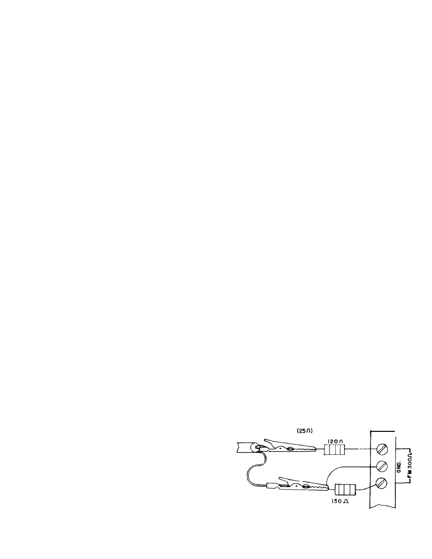
FROM
GENERATOR
1
A74-1479-01
Figure 6 - Dummy Antenna for FM Alignment
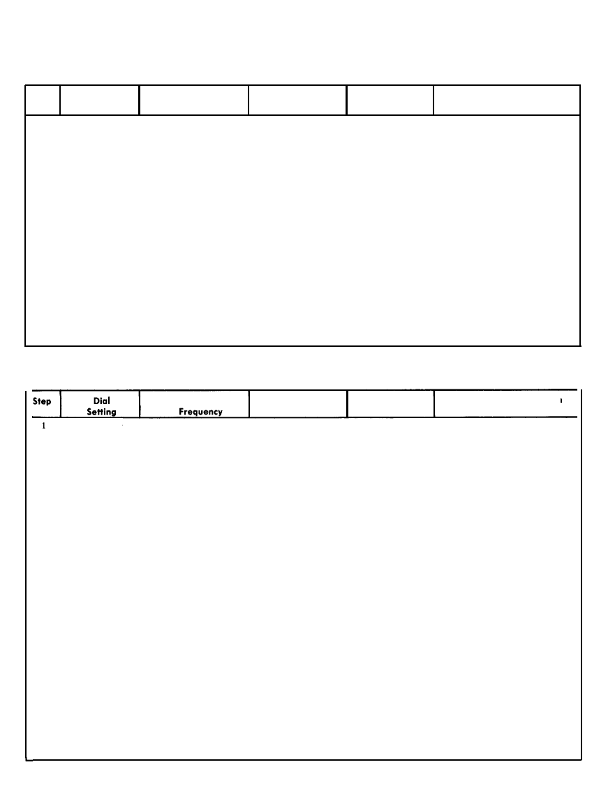
TABLE I - AM ALIGNMENT CHART (See Figure 7)
NOTE: Set Selector Switch to AM
Step
Band & Dial Generator
Setting Frequency
Signal
Input
Indicator and
Connection
Adjustment and Indication
1 Indicator at Ex-
455 kHz 30%, AM Mod Through .05 MFD DC VTVM at TP-, Adjust T2 and T3 for maxi-
treme left end of at 400 Hz. Generator capacitor to TP-22,
2, terminal 2 of mum indication on meter. As
dial output level 5µV,
terminal 22 of Al.
Al.
a gain check, input should be
maximum less than 4µV for an. output
0.5 vdc above noise.
2 AM at 600 kHz
600 kHz, 30% AM Mod AM EXTERNAL Oscilloscope and Adjust Tl and Ant Coil L103
at 400 Hz. Generator ANT. and GND. dc VTM at TP-2, for maximum indication on
output level 1 mV,
terminal 2 of Al. meter. Keep dc output level
maximum. below 1 volt by reducing in-
put as peak is approached.
3 AM at 1400 kHz
1400 kHz, 30% AM Mod Same as Step 2, Same as Step 2, Adjust (first) AM OSC TRIM,
at 400 Hz. Generator o above. above. (then) AM ANT TRIM for
output level 5 0 0 µ V ,
maximum indication on meter.
maximum. Keep dc output level below 1
volt by reducing input as peak
is approached.
4 Repeat steps 2 and 3, above until all outputs are peaked at the proper frequencies. As a gain
check, 600 kHz input should be less than 3OµV for output of 0.5 vdc above noise, and 1400
kHz input should be less than 35µV for output of 0.5 vdc above noise.
TABLE II - FM ALIGNMENT CHART (See Figure 7)
Set FM MUTE Switch to OUT (button out), and Selector Switch to FM (button in).
Generator Signal Input Indicator &
Adjustment and indication
Point Connection
Check color code (paint dot) on ceramic filters FL1 and FL2 (figure 2) to determine IF center
frequency. Frequency for each color is: Green (10.60), Black (10.65), Blue (10.67), Red (10.70).
Orange (10.73), White (10.75), Yellow (10.80). Both filters in any one receiver must have same
colored dots.
2 FM at 98 MHz 98 MHz ±300 kHz sweep FM 300 ohm an-
O s c i l l o s c o p e a t Adjust T4 and FM IF XFMR
deviation at 400 Hz mod-
tenna terminals TP-6, terminal 6 of (in tuner) for max gain with
ulation. Generator out-
through dummy Al. good symmetry. Adjust T5
put level approx. 2OµV.
antenna (see fig-
for optimum “S” curve.
gure 6)
3 FM at 104 MHz
1 0 4 M H z ±75 kHz
Same as Step 2, Tuning Meter Check tracking. If necessary,
sweep deviation at 400 above adjust FM OSC TRIM, FM
Hz modulation. Genera-
RF TRIM and FM ANT TRIM
tor output level approx. for max gain.
lOµV.
4 FM at 90 MHz 90 MHz µ75 kHz sweep Same as Step 2, Tuning Meter Check tracking. If necessary,
deviation at 400 Hz mod-
adjust FM OSC COIL, FM RF
ulation Generator out-
COIL and FM ANT COIL for
put level approx. 1OµV.
max gain. FM OSC COIL is
adjusted by carefully compres-
sing turns closer together with
an insulated instrument.
NOTE: Repeat steps 3 and 4 as required to obtain satisfactory tracking at both frequencies.
FM MUTING CHECK
5 FM at 98 MHz 98 MHz ±75 kHz sweep Same as Step 2, a c V T V M a n d Record ac output level on
deviation at 400 Hz. above scope a t T P - 8 , VTVM
Generator output level terminal 8 of Al.
20µV.
6 Same as Step 5, Same as Step 5, above. Same as Step 2, Same as Step 5, Depress FM MUTE switch.
above. above. above. Reading at TP-8 should drop
about 3 db. If required, adjust
MUTE ADJ (R90) for proper
reading.
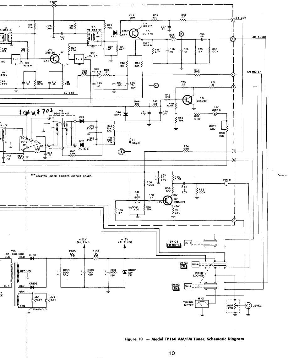
6
Wyszukiwarka
Podobne podstrony:
Digital ECU Tuner III Manual
Backup of Tv Tuner Cards Waikato Li
H LCD1504 ESD Tuner
PCB layout tuner layout for H LCD2005 from KTV on 5Jun
bhf marienfelde gueterschuppen 1890 120 bogen 01 02
TUNER TELEWIZYJNY
do you need an antenna tuner
bhf marienfelde empfangsgebaeude 1890 120 bogen 01 03
bhf marienfelde abortlgebaeude nord 87 bogen 01 01
bhf marienfelde stellwerk sbd 120 bogen 01 01
Don Bogen An Algebra (poetry) (pdf)
tuner tmc z Audi S4B5 navi plus z S4B5 licznik z S4B5, auta, elektryka, elekt AUDI
inststrukcja tuner Medion
Tuner Diora AS 952
75 Nw 07 Tuner UKF
2 sposób instalacji tunera, medion tv-tuner 7134
Guitar Tuner
Digital ECU Tuner III Manual
więcej podobnych podstron