
1
ELECTRICAL CHECKS AND ADJUSTMENTS
FOR SitDrive
ELECTRIC LIFT TRUCKS
GENERAL
This section has the checks, adjustments and repair pro-
cedures for the parts of the electrical system that are not
part of the EV–1, EV–1B, EV–1W, EV–100 or EV–200
motor controllers. This section applies to the electric
SitDrive
models. It also has the adjustment proce-
dures for the control cards of these controllers since
these systems are part of the electrical systems. To
check, adjust or repair the parts of the motor controllers
that apply to your lift truck, see one of the following con-
troller sections:
•
PROCONTROL (EV–1B DUAL MOTOR
CONTROL), 2200 SRM 91
•
EV–1 MOTOR CONTROLLER,
2200 SRM 155
•
EV–100 MOTOR CONTROLLER,
2200 SRM 288,
•
EV–1W MOTOR CONTROLLER,
2200 SRM 409
•
EV–200 MOTOR CONTROLLER,
2200 SRM 414
See the section BATTERY INDICATORS, 2200
SRM 138 to adjust or replace the battery indicator. See
the section INSTRUMENT PANEL INDICATORS
AND SENDERS, 2200 SRM 143 to check and replace
the other instrument panel indicators and the senders.
NOTE: This section does not include the EV–100LX/
ZX and EV–200LX/ZX series of motor controllers. See
the section EV–100LX/ZX AND EV–200LX/ZX
MOTOR CONTROLLERS, 2200 SRM 460, for in-
formation on these series of motor controllers.
WARNING
Do not operate a lift truck that needs adjustment or
repairs. Report the need for adjustment or repairs
immediately. If adjustment or repair is necessary,
put a “DO NOT OPERATE” tag in the operator’s
area. Remove the key from the key switch.
Some of the checks and adjustments are done with
the battery connected. Never have any metal on your
fingers, arms or neck. These metal items can acci-
dentally make an electrical connection and cause an
injury.
CAUTION
Correct meter polarity is necessary for some checks.
Meter correct positive is indicated as (+). Meter cor-
rect negative is indicated as (–).
Use a meter with a minimum rating of 20 000 ohms
per volt to make measurements. Most digital volt
meters are good.
Most of the components of the motor controllers cannot
be adjusted. The control card has adjustments for cor-
rect operation of some functions. Some components that
have inputs to the controller have installation adjust-
ments. Following are the correct procedures for adjust-
ing control cards and tor other components. These com-
ponents include the following:
1. Key Switch
2. Start Switch
3. Brake Switch
4. Foot Switch
5. Seat Switch
6. Direction (FWD REV) Switches
7. Steering Potentiometer (J25–35A)
8. Accelerator Potentiometer
WARNING
Some checks and adjustments in this section must be
done with the battery connected and power applied
to the controller. Lift truck movement during checks
or adjustments can cause personal injury. Raise the
drive wheels to prevent lift truck movement. See the
Operating Manual or Preventive Maintenance SRM
section for your lift truck to raise the drive wheels.
NOTE: Some checks and adjustments are difficult to do
unless another person can operate the controls. If you
are working alone, put a weight in the seat to close the
seat switch. If your lift truck has a seat brake, use a block
behind the lower actuator bar to release the seat brake
when the operator in not in the seat. Put the voltmeter in
a position so that you can see it from the operator area.
You can usually operate the controls with your hand and
also make the voltage measurements.
2
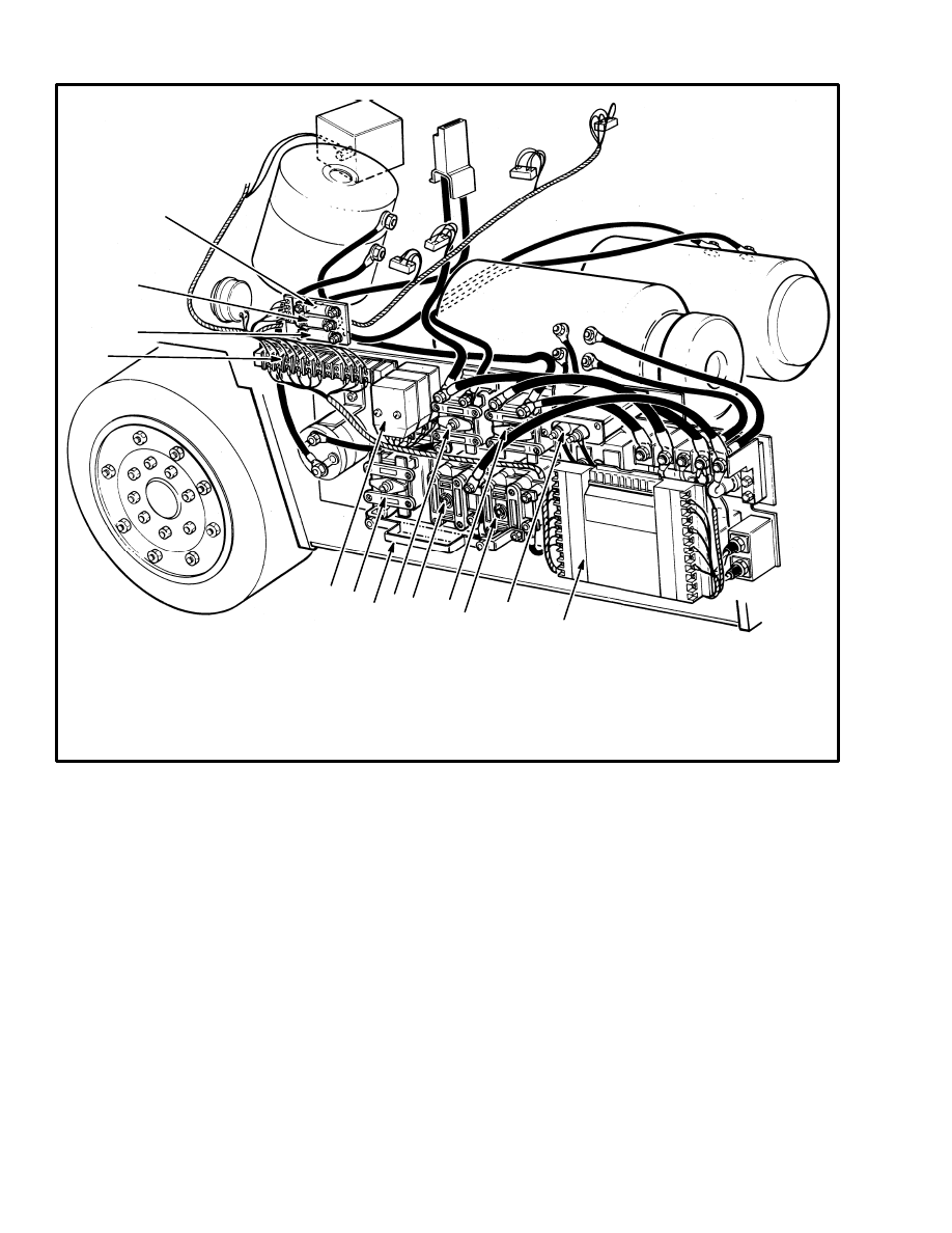
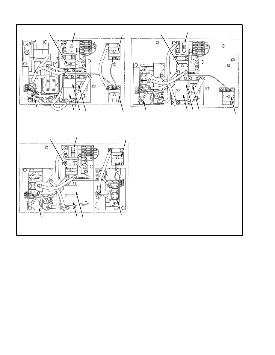
FIGURE 1. COMPONENT LOCATIONS, EV–1 FOR E/J25–60A/B
5970
13
1
2
3
5 6
7
8
9
10
11
12
1. TERMINAL STRIP
2. ELECTRONIC DRIVERS (PMT, 1A, FW)
3. FIELD WEAKENING CONTACTOR
4. FIELD WEAKENING RESISTOR
5. CONTACTOR, HYDRAULIC PUMP
6. FORWARD CONTACTOR
7. CONTACTOR 1A
4
8. REVERSE CONTACTOR
9. CAPACITOR C1
10. MOTOR CONTROL MODULE
11. FUSE, TRACTION CIRCUIT
12. FUSE, STEERING MOTOR
13. FUSE, HYDRAULIC PUMP CIRCUIT
3
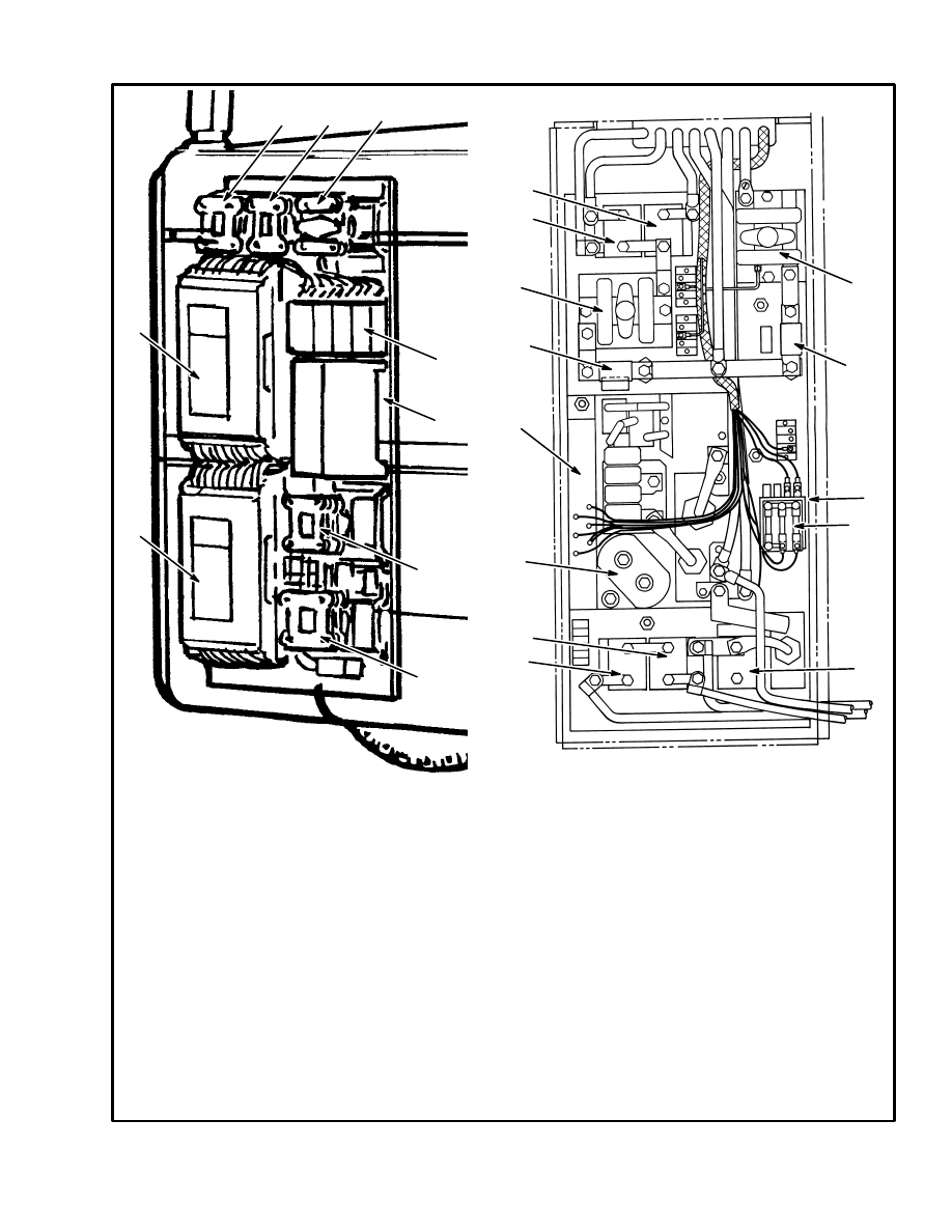
FIGURE 2. COMPONENT LOCATIONS, J25–35A/B
11740
6475
EV–1B PROCONTROL
(DUAL TRACTION MOTOR CONTROLLER)
EV–100 MOTOR CONTROLLER
FOR J25–35B
FOR J25–35A
2
1. RIGHT MOTOR CONTROL MODULE
2. LEFT MOTOR CONTROL MODULE
3. LEFT FORWARD CONTACTOR
4. LEFT REVERSE CONTACTOR
5. HYDRAULIC PUMP CONTACTOR
6. ELECTRONIC DRIVERS (4)
7. PROPORTIONAL CONTROL MODULE
8. RIGHT FORWARD CONTACTOR
9. RIGHT REVERSE CONTACTOR
1
3
4
5
6
7
8
9
8
1
2
3
4
5
6
9
10
11
12
13
1. CONTROL CARD
2. CAPACITOR C1
3. LEFT FORWARD CONTACTOR
4. LEFT REVERSE CONTACTOR
5. BALANCE CONTACTOR
6. FUSES, CONTROL CIRCUIT AND
STEERING
7. ELECTRONIC DRIVERS (PMT, 1A, D)
8. FUSE, HYDRAULIC PUMP
9. HYDRAULIC PUMP CONTACTOR
10. RIGHT REVERSE CONTACTOR
11. RIGHT FORWARD CONTACTOR
12. CONTACTOR 1A
13. FUSE, TRACTION CIRCUIT
7
4
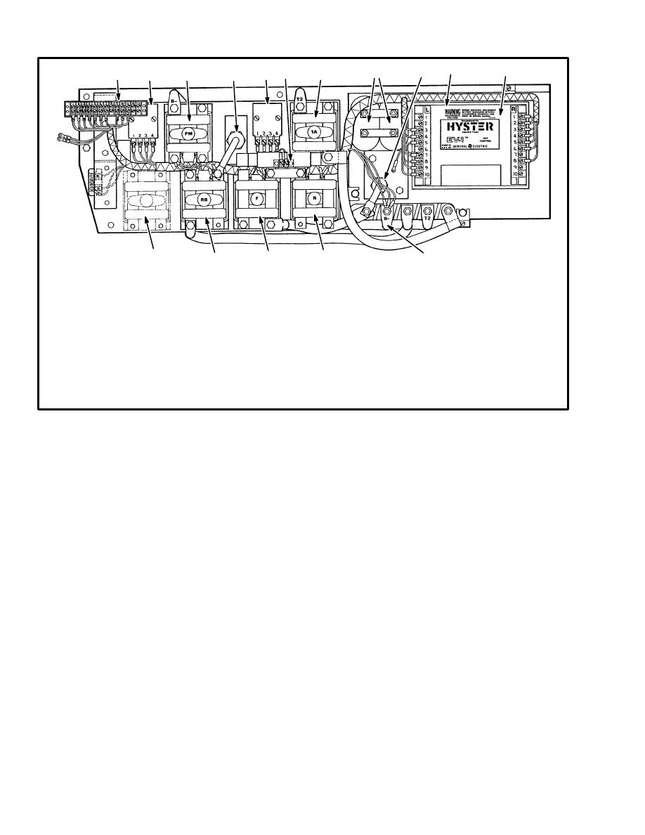
FIGURE 3. COMPONENT LOCATIONS, EV–1W
12241
11
1. TRACTION CARD
2. CAPACITOR C1
3. SCR 1 (UNDER TRACTION CARD)
4. SCR 2 (UNDER TRACTION CARD)
5. SCR 5 (UNDER TRACTION CARD)
6. DIODE D4
7. POWER CONNECTION (–)
8. REVERSE CONTACTOR
9. FORWARD CONTACTOR
10. REGENERATIVE BRAKING CONTACTOR
11. FIELD WEAKENING CONTACTOR
(36–48 VOLTS ONLY)
11. SOFT START CONTACTOR, HYDRAULIC PUMP
(E4.50–5.50B 72–80 VOLTS ONLY)
12. TERMINAL BOARD
13. ELECTRONIC DRIVERS (3) (1A, FW, RB)
14. HYDRAULIC PUMP CONTACTOR
15. DIODE D7
16. ELECTRONIC DRIVER (PMT)
AND TIMER FOR SRO (1)
17. REGENERATIVE BRAKING SENSOR
18. CONTACTOR 1A
2
1
3, 4, 5
6
18
17
13
15
14
16
12
10
9
8
7
5
11482
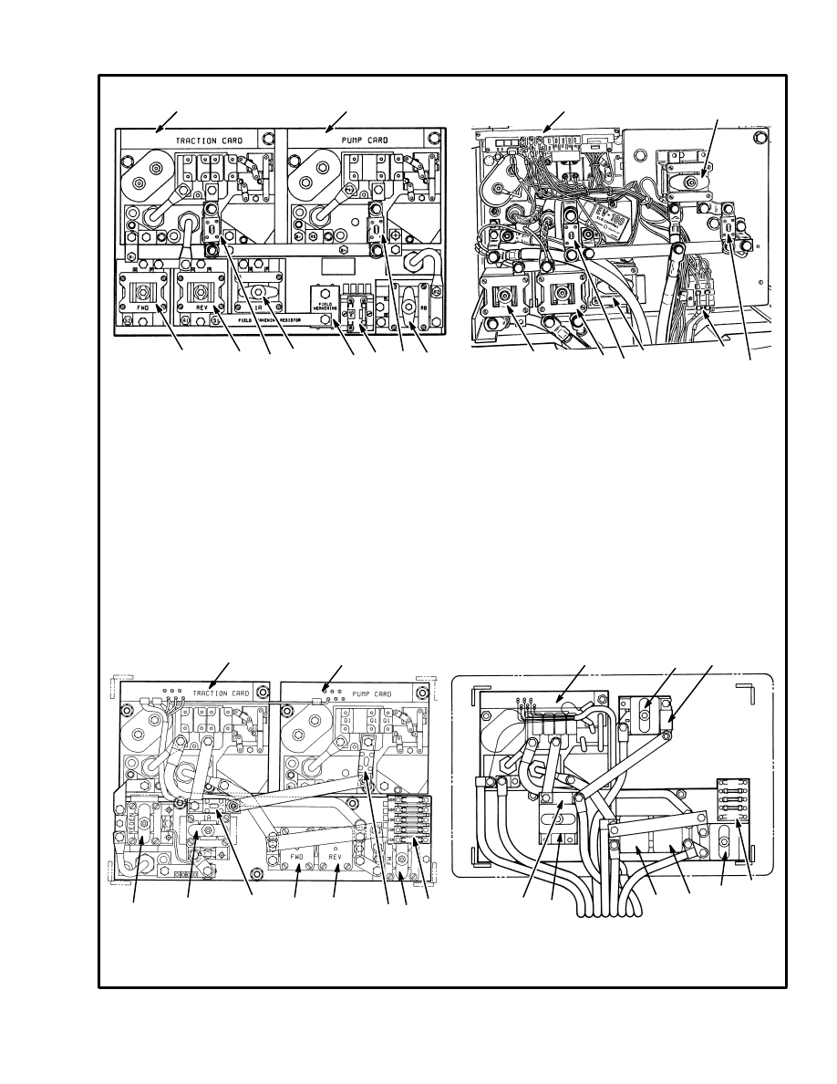
FIGURE 4. TYPICAL COMPONENT LOCATIONS OF THE EV–100 CONTROLLER
1. TRACTION CARD REGENERATIVE BRAKING
2. TRACTION CARD WITHOUT REGENERATIVE
BRAKING
3. EV–100 CONTROL, HYDRAULIC PUMP MOTOR
4. CONTACTOR, HYDRAULIC PUMP MOTOR
5. CONTACTOR, REGENERATIVE BRAKING
6. CONTACTOR, 1A
11531
MOTOR CONTROLLER WITH REGENERA-
TIVE BRAKING, 1A BY–PASS, AND SCR
CONTROLLER FOR HYDRAULIC PUMP
MOTOR CONTROLLER WITH 1A BY–PASS,
AND CONTACTOR CONTROL FOR HYDRAU-
LIC PUMP
7. CONTACTOR, FORWARD DIRECTION
8. CONTACTOR, REVERSE DIRECTION
9. CONTACTOR, FIELD WEAKENING
10. FUSE, TRACTION CIRCUIT
11. FUSE, HYDRAULIC PUMP
12. FUSES, CONTROL CIRCUIT AND
STEERING
3
1
2
4
9
8
7
6
5
7
8
6
10
11
12
11
10
12
BEFORE NOVEMBER 1987
12173
12124
1
2
3
4
MOTOR CONTROLLER WITH REGENERA-
TIVE BRAKING, 1A BY–PASS, AND SCR
CONTROLLER FOR HYDRAULIC PUMP
MOTOR CONTROLLER WITH 1A BY–PASS,
AND CONTACTOR CONTROL FOR HYDRAU-
LIC PUMP
5
6
6
7
7
8
8
9
9
10
11
12
12
10
11
AFTER NOVEMBER 1987
6
FIGURE 5. EV–200 AND EV–100 COMPONENT LOCATIONS FOR E3.50–5.50XL (E70–120XL)
EV–200 TRACTION CONTROLLER
WITH CONTACTOR HYDRAULIC
CONTROL (2 PUMP MOTORS)
EV–100 TRACTION CONTROLLER
WITH CONTACTOR HYDRAULIC
CONTROL (1 PUMP MOTOR)
EV–100 TRACTION CONTROLLER AND
EV–100 HYDRAULIC PUMP CONTROLLER
12275
1. TRACTION CONTROLLER WITH
REGENERATIVE BRAKING
2. MOTOR CONTROLLER, HYDRAULIC
PUMP MOTOR
3. CONTACTOR, HYDRAULIC PUMP MOTOR
4. CONTACTOR, REGENERATIVE BRAKING
5. CONTACTOR, 1A
6. CONTACTOR, FORWARD DIRECTION
7. CONTACTOR, REVERSE DIRECTION
8. CONTACTOR, FIELD WEAKENING
(NOT ON ALL UNITS)
4
4
4
3
3
3
3
2
1
1
1
5
5
5
6 7
6 7
6 7
8
8
CONTROL AND POWER FUSES
(See FIGURE 1. Through FIGURE 5.)
The condition of fuses can normally be checked by
looking at them. Some fuses do not change in appear-
ance and must be checked with an ohmmeter. Discon-
nect the battery before checking fuses. Sizes of the fuses
are shown in TABLE 1.
On lift trucks with an EV–1 controller, a power fuse
panel is found behind the access panel on the left side of
the lift truck above the electrical compartment. There
are three fuses on the fuse panel: a fuse for the traction
circuit, a fuse for the power steering motor and a fuse for
the hydraulic pump circuit. A separate control fuse is in-
stalled in the wire that is the supply for the key switch
and the control circuit. This fuse is found under the floor
plate next to the power fuse panel. The fuses can be
checked electrically with an ohmmeter after they are re-
moved from the power fuse panel.
On lift trucks with an EV–100 controller, the fuses are
found on the motor controller. The power fuses for the
traction circuit and for the hydraulic pump are found on
the (+) bus bar. The control fuse and the fuse for the
power steering are in fuse holders on the stack of elec-
tronic driver modules.

7
TABLE 1. FUSES
LIFT TRUCKS
POWER FUSES
CONTROL CIRCUIT FUSES
Traction
Hyd.
pump
Steering
Control
Battery
Ind.
Hour
Meter
LED
Display
Accel.
Card
E20–30B/BS/BH
225A
175A
30A
15A
N/A
N/A
N/A
10A
E30–60B/BS
36–48 Volts
72–80 Volts
250A
175A
200A
150A
30A
10A
N/A
N/A
N/A
10A
E60–120B
36–48 Volts
72–80 Volts
200A (2)
175A
200A (2)
150A
30A
10A
N/A
N/A
N/A
10A
E/J1.25––3.00XL (E/J25–60XL)
500A
325A
40A
15A
15A
10A*
10A
N/A
E3.5–5.5XL (E70–120XL)
800A
325A (2)
40A (2)
15A
15A
10A*
10A
N/A
J25–35A, J25–35B
500A
325A
40A (2)
15A
N/A
N/A
N/A
10A
J40–60A, J50–60AS
36–48 Volts
72–80 Volts
250A
175A
200A
150A
30A
15A
N/A
N/A
N/A
N/A
*Later production lift trucks only. Earlier production lift trucks do not have a separate fuse.
N/A = Not Applicable
CONTROL CARD
The control card is a printed circuit board with elec-
tronic parts in a plastic case. The control card has two 6
pin plugs (PA and PB) that connect the signal wires be-
tween the parts of the controller and the control card. A
14 pin plug (PC) connects the control card to the func-
tions for SCR 1, SCR 2, and SCR 5. Two machine
screws at the bottom of the plastic case fasten the control
card to the mounting plate. The control card for each
function and the position of each control card is the same
in both configurations of the controller.
Different control cards are used in the electric lift trucks
made by Hyster Company. A replacement control card
must be the same part number as the control card that
was removed. Lift trucks that are equipped with the re-
generative braking function use a different control card
than lift trucks that only use a plugging function. These
two control cards for the traction circuit have a different
shape and must not be used as a replacement for the
other control card. The control card used in lift trucks
equipped with an SCR control for the hydraulic pump
can not be used for one of the control cards for the trac-
tion circuit. A bad control card must be replaced because
it cannot be repaired by service persons.
The control card for the traction circuit has an ”Static
Return to OFF” (SRO) circuit. The key switch and seat
switch must be closed before the accelerator is moved to
operate the lift truck. A service person must understand
the SRO sequence when troubleshooting. The SRO is a
safety circuit that normally prevents the FORWARD or
REVERSE travel of the lift truck unless the operator is
in the correct position at the controls. If a service person
must operate the lift truck with a by–pass on the SRO
circuit, raise the drive wheels so that the lift truck can not
move and cause an accident.
The control card for the traction circuit has a ”Pulse
Monitor Trip” (PMT) circuit that checks for a malfunc-
tion of SCR 1. If SCR 1 does not operate with pulses, but
stays ”ON” continuously, the controller will open the di-
rection contactor and stop the lift truck.
CONTROL CARD ADJUSTMENTS
WARNING
Never operate a lift truck using a control card that
has not been adjusted. The lift truck will not operate
as expected and can cause personal injury or dam-
age. Adjust the control cards according to the follow-
ing procedures.
NOTE: To check and replace the control card or other
parts of the motor controller, see the correct section for
the controller as shown on page 1.
8
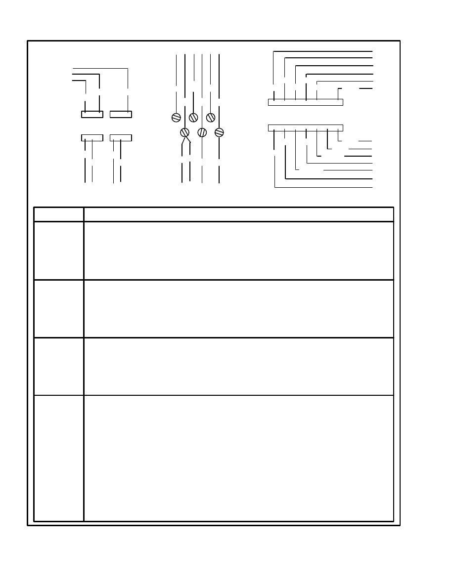
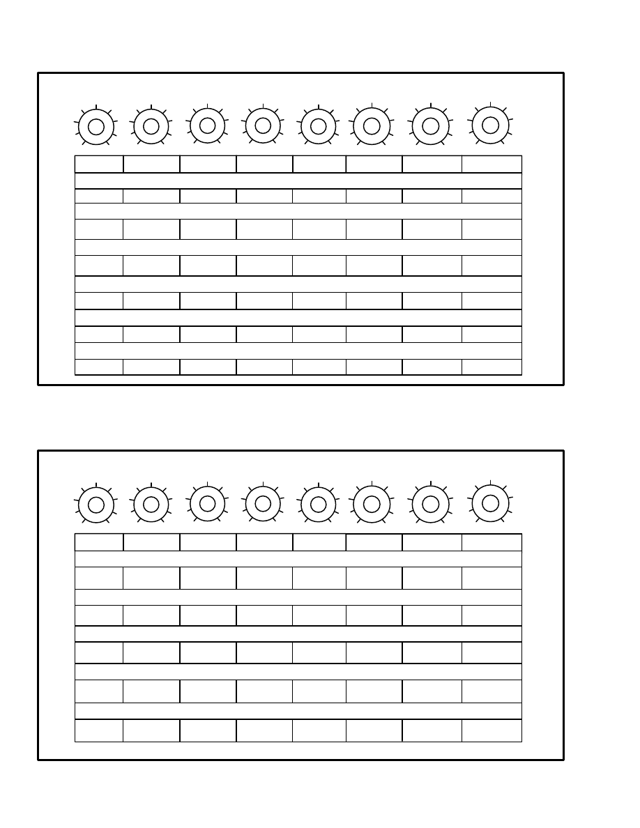
FIGURE 5. TERMINAL AND PIN ARRANGEMENTS FOR THE CONTROL CAR
(TRACTION CIRCUIT)
NO.
FUNCTION
PA1
PA2
PA3
PA4
PA5
PA6
PB1
PB2
PB3
PB4
PB5
PB6
TB1
TB2
TB3
TB4
TB5
TB6
PC1
PC2
PC3
PC4
PC5
PC6
PC7
PC8
PC9
PC10
PC11
PC12
PC13
PC14
Signal to energize the regenerative braking electronic driver (wire 32).
Not used.
Voltage check for regenerative braking function (wire 17).
Signal to the regenerative braking sensor (wire 22).
Signal to the regenerative braking sensor (wire 21).
Not used.
Not used.
Not used.
Signal to energize the field weakening electronic driver (wire 38).
Signal to energize the PMT electronic driver (wire 24).
Signal to energize the 1A electronic driver (wire 34).
Not used.
5 volt supply to accelerator potentiometer (wire 29).
Signal connection between START switch and control card (wire 57A).
Voltage input from timer circuit (wire 7).
Battery voltage supply from key switch (wire 10).
Voltage input from FORWARD direction switch (wire 6).
Voltage input from REVERSE direction switch (wire 8).
Signal wire from SCR 1 thermal protector (black wire).
Battery negative (brown wire).
Signal wire from current sensor (traction circuit) (yellow wire).
Signal wire from current sensor (traction circuit) (green wire).
Signal wire from SCR 1 thermal protector (gray wire).
Not used.
Battery positive voltage (white wire).
Signal wire to SCR 1 gate (blue/white wire).
Signal from SCR 1 cathode (blue wire).
Signal wire to SCR 2 gate (white/red wire).
Connection between filter for SCR 2 and control card (red wire).
Signal wire to SCR 5 gate ( white/violet wire).
Connection between filter for SCR 5 and control card (violet wire).
Sensor wire for voltage check across capacitor C1 (orange wire).
d d d
d d d
d d d
d d d
1 2 3
1 2 3
4 5 6
4 5 6
A
B
C
d d d
d d d
1
2
3
4
5
6
d d d
d d d
d
d
7
8 9 10 11 12
14
13
TB1
TB2
TB3
TB4
TB5
TB6
32
22
17
38
21
24
34
29
57
A
7
10
6
8
6
8
10 10
WHT
ORN
PUR
W/PUR
GRY
GRN
RED
YEL
BRN
W/RED
BLU
BLK
W/BLU
PLUG A
PLUG B
TERMINALS
PLUG C
FIGURE 6. TERMINAL AND WIRE ARRANGEMENTS FOR THE CONTROL CARD
(TRACTION CIRCUIT)
9
This section has a description of the adjustments that are
on the control card for the motor controllers. Each ad-
justment is a potentiometer in the control card that turns
from a minimum control at (1) to a maximum control at
(9). The adjustments are normally set to the number
shown in the specification tables for each model series
of lift truck. See TABLE 2. through TABLE 7.
NOTE: Labels in the electrical compartment have the
factory settings of the adjustment screws for the control
cards.
NOTE: Make sure the battery has a minimum corrected
specific gravity of 1.250.
Control card adjustment is required when traction motor
or pump motor circuit parts are replaced. Adjustment
can also be required for different performance needs.
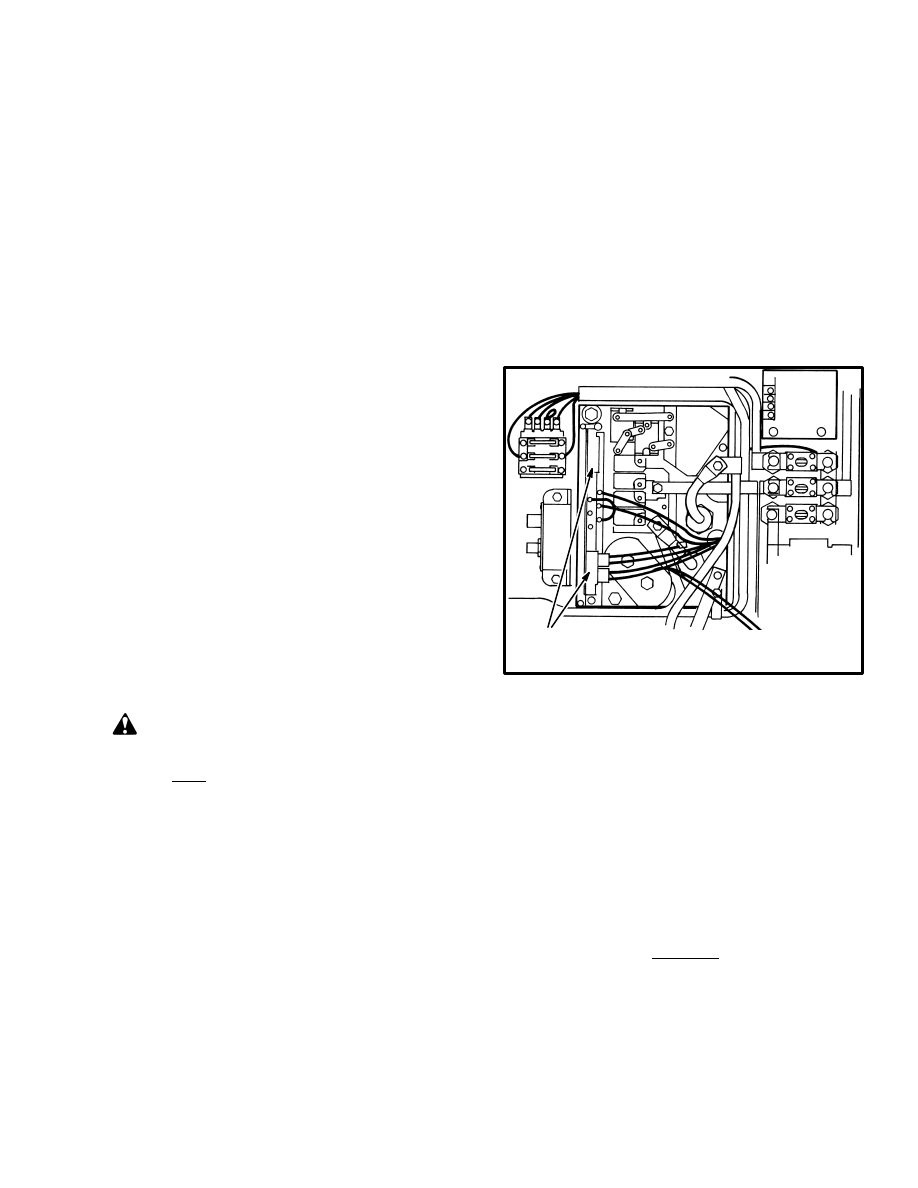
For access to the adjustment screws on the control cards,
remove the cover over the electrical compartment and
open the adjustment screw covers. Open the screw cov-
ers and use a small screwdriver to turn the adjustment
screw counterclockwise to the stop. Use the end of the
screw slot at the “1” position for the reference. See
TABLE 2. through TABLE 7. Turn the adjustment
screw to the correct setting shown in TABLE 2. through
TABLE 7. and the labels or described in the procedure.
NOTE: Not all units have all the functions covered by
these adjustment procedures. Do only the adjustments
for your lift truck model.
CAUTION
The “C/L”, “REGEN” and “REGEN D.O.” potenti-
ometers must be adjusted to the factory settings
shown in TABLE
2. through TABLE 7. The
“CREEP”. “C/A” and “PLUG” potentiometers can
be adjusted for specific applications.
NOTE: The settings of the regenerative braking poten-
tiometers and the “PLUG” potentiometer set the stop-
ping distance of the lift truck. The settings operate to-
gether and must be set in sequence. Adjust them in this
sequence: “REGEN C/L”. “REGEN D.O.” and
“PLUG”.
Adjusting Creep Speed, “CREEP”
The “CREEP” speed adjustment sets the minimum
speed for the lift truck. The adjustment of the accelerator
potentiometer must be correct before the “CREEP” ad-
justment is made. At the correct setting, the SCR will
hum, but the lift truck will not quite move as the direc-
tion contactors are first energized. A very slow speed is
good for most operations. The setting shown in
TABLE 2. through TABLE 7. is correct for normal op-
erations. The lift truck must move smoothly when the
direction/speed control is moved a small amount. The
fastest minimum speed occurs when the “CREEP” po-
tentiometer is adjusted to the “9” position. Very rough
operation will occur if these lift trucks have a setting
much above the normal setting shown in TABLE 2.
through TABLE 7. and the label.
FIGURE 7. EV–100 MOTOR CONTROLLER
MODULE
1. ADJUSTMENT SCREW COVERS
12297
1
This adjustment can be set at a different number than
shown in the specifications. Some users want more
movement of the accelerator (MONOTROL) pedal be-
fore the direction contactors close.
Adjusting Controlled Acceleration, “C/A”
The accelerator (MONOTROL) pedal does not have to-
tal control of the maximum rate of acceleration. This ad-
justment controls the maximum rate that the average
voltage is increased by the controller to accelerate the
traction motor. Too high a rate of acceleration increases
the wear of the brushes in the traction motor. The accel-
eration is also selected to give a smooth acceleration for
better load handling. The acceleration rate can be ad-
justed for the conditions of a user. Turn the potentiome-
ter counter–clockwise to decrease the acceleration rate.

10
Adjusting Current Limit, “C/L”
Set the current limit to the number shown in TABLE 2.
through TABLE 7. and the label. Do not change the cur-
rent limit without the approval of a Hyster Company
Service Engineer. If the current limit is set higher than
the specifications, parts of the traction circuit can be
damaged.
There are two faults that can cause the current in the
traction circuit to increase over the maximum limit:
•
a disconnected yellow wire from the motor
current sensor
•
a bad logic card
Both of these faults can cause damage to other parts of
the traction circuit.
The correct current draw from the battery is shown in
TABLE 2. through TABLE 7.
If the lift truck is equipped with power steering, add the
following values to the current values shown in
TABLE 2. through TABLE 7.:
13 amperes [hydraulic oil at 16
°
C (60
°
F)]
10 amperes [hydraulic oil at 43 to 54
°
C (110 to
130
°
F)]
NOTE: A change was made in the control card during
August 1986 which requires a different setting of the
C/L limit than control cards of earlier manufacture.
Control cards made before August 1986 have a 099
mark on them. The part numbers for these control cards
are 325751, 325753, and 359787. These control cards
must be set to 9 for the current limit.
Control cards made after August 1986 have a 098 mark
on them and must be set to 5 for the current limit. The
actual current limit value for all control cards of these
part number series is approximately 235 amperes.
The controller and the traction circuit can be damaged if
the current flow is greater than the design specifications.
A current sensor is installed in the controller to check the
current flow. When the current becomes greater than the
setting on the control card, the current limit overrides
the other signals to the oscillator to decrease the pulse
width and frequency. Sometimes the current limit must
be checked in a lift truck. The following procedure is
used to check if the current limit is the same as the set-
ting on the control card. A damaged SCR 1 or SCR 5 can
be an indication that the current limit is set too high.
TABLE 2. through TABLE 7. show the typical settings
for the control cards. Also see the section CAPACITIES
and SPECIFICATIONS for the model series of lift
trucks for current limits.
CAUTION
The battery shunt method of checking the current
limit can give errors because of variations in the trac-
tion motor and temperature. If the battery shunt
method must be used to check the current limit, use
this method carefully so that the controller and trac-
tion circuit is not damaged.
The ammeter shunt must be installed in the arma-
ture circuit and not the battery circuit if the follow-
ing current limits are checked:
“PLUG”
“REGEN C/L”
“REGEN D.O.”
1. Make sure the battery is charged and has a minimum
specific gravity of 1.260. Raise the drive wheels from
the surface.
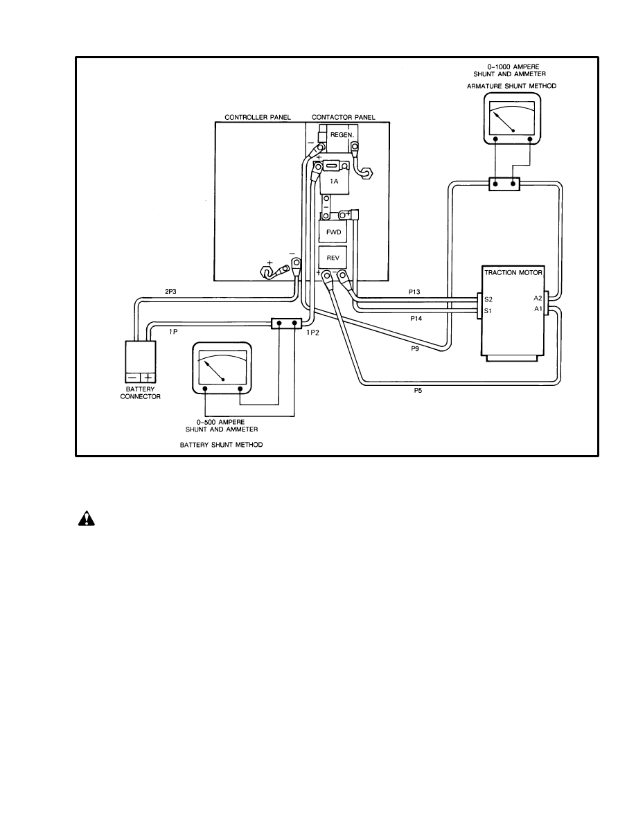
2. Connect a 0–500 ampere ammeter between the bat-
tery and the power circuit. Make sure that the polarity is
correct. See FIGURE 8. Make sure the ammeter cables
are as short as possible. Install a jumper on the brake
switch so that it does not interrupt the operation of the
controller. Disconnect the wire at terminal 1 of the 1A
electronic driver so that the 1A contactor can not close,
or put cardboard between the contacts to prevent current
flow between the contacts.
3. You must be on the operator’s seat. Turn the key
switch to the “ON” position and apply the brake so that
the drive wheels can not rotate.
4. Look at the ammeter and push the accelerator
(MONOTROL) pedal for maximum forward speed.
Quickly check the ammeter indication and release the
pedal.
11
FIGURE 8. CONNECT THE DC AMMETER
CAUTION
Do not cause the traction motor to stall for more than
10 seconds at a time. The traction motor will quickly
become hot. You want to set the current limit at oper-
ating temperatures or less. Give enough time be-
tween checks so that the traction motor can cool. Do
not hold the accelerator (MONOTROL) pedal
pushed down while adjusting the current limit. Ro-
tate the drive motor between checks.
5. Make an adjustment to the “C/L” potentiometer. Turn
the adjustment clockwise to increase the current limit.
Repeat Steps 4 and 5 until the correct current limits are
set.
6. Turn the key switch to the “OFF” position. Remove
the ammeter and remove the jumper from the brake
switch. Connect wire to terminal 1 of the 1A electronic
driver or remove the cardboard from between the con-
tacts. Lower the drive wheels to the surface.
Adjust “1A TIME”
The “1A TIME” adjustment permits the SCR control to
bring the traction motor up to speed before the 1A con-
tactor closes. This time delay prevents full battery cur-
rent being applied across the traction motor when it is
not rotating. This adjustment also permits smoother op-
eration of the lift truck. The control card begins “1A
TIME” when the accelerator voltage is decreased to less
than 0.5 volts. “1A TIME” is normally 1–3 seconds.
NOTE: Some models have no “1A Drop Out”. When
these lift trucks stall, it takes only a few seconds to cause
the fuse for the traction circuit to fail open. This protects
the traction motor from high heat created by the high
current produced when the traction motor is at stall.
12
1
9
5
1
9
5
1
9
5
1
9
5
1
9
5
1
9
5
1
9
5
1
9
5
CREEP
C/A
C/L
1A TIME
PLUG
F.W.P.U.
F.W.D.O.
6
5
4
6
6
400–450
6
5
3
7
6
150–180
7
9
7
––
––
3
6
5
6
400–450
150–180
TABLE 2. CONTROL CARD ADJUSTMENTS FOR THE TRACTION MOTOR CIRCUIT
E20–30BS, E20–30BH (36–48 volts)
E30–60BS (36 volts)
EV–1B MOTOR CONTROLLER ADJUSTMENTS (E20–120B)
5
6
4
E30–60BS (48 volts
E30–60BS (72–80 volts)
E60–120B (36–48 volts)
Amps
Amps
6
4.5
5
4.5
4
1A D.O.
––
––
––
––
6
5
6
9
Amps
Amps
6
––
––
9
4.5
9
6
2
2
E60–120B (72–80 volts)
1
9
5
1
9
5
1
9
5
1
9
5
1
9
5
1
9
5
1
9
5
1
9
5
CREEP
C/A
C/L
1A TIME
PLUG
F.W.P.U.
F.W.D.O.
6
5
9
4
6
6
400–450
230 amp*
1–3 sec
6
5
4
6
6
230 amp*
150–180
8
4
1
––
––
––
485 amps*
––
6
4
1
3
––
510 amps*
––
* Maximum current must be checked with the ammeter shunt in the battery circuit.
J25–35A (24 volts)
TABLE 3. CONTROL CARD ADJUSTMENTS FOR THE TRACTION MOTOR CIRCUIT
J25–35A (36 volts)
EV–1B MOTOR CONTROLLER ADJUSTMENTS (J25–120AS)
4
––
––
J40–60A, J50–60AS (36 volts)
J40–60A, J50–60AS (48 volts)
J40–60A, J50–60AS (72–80 volts)
Amps
Amps
400–450
150–180
Amps
Amps
6
6
5
6
7
3
6
1A D.O.
230 amp*
1–3 sec
1–3 sec
––
––
13
1
9
5
CREEP
C/A
C/L
1A TIME
PLUG
REGEN C/L REGEN D.O.
F.W.P.U.
F.W.D.O.
3.5
––
––
––
––
TABLE 4. CONTROL CARD ADJUSTMENTS FOR THE TRACTION MOTOR CIRCUIT
CONTROL CARD IDENTIFICATION NUMBER: IC3645OSC2–R9
EV–1W MOTOR CONTROLLER ADJUSTMENTS [E3.00–5.50B (E60–120B Only)]
E3.00–5.5B (E60–120B) 36–48 volts
4.5
E5.00–5.5B (E100–120B) 72–80 volts
5
9
4.5
4
3.5
6
5
9
6
2
3.5
3.5
CREEP
C/A
C/L
1A TIME
1A D.O.
PLUG
NOT USED
REGEN C/L
REGEN D.O.
F.W.D.O.
F.W.P.U.
1A D.O.
––
––
Adjust 1A Drop Out, “1A D.O.”
The “1A Drop Out” adjustment sets the maximum limit
of traction motor current during operation with contac-
tor 1A closed. When this current limit is reached, the
contactor 1A opens and the traction motor is controlled
by SCR 1. This current limit prevents damage to the
traction circuit during operation with contactor 1A
closed. This adjustment can be set at a lower number
than the number in the specification in TABLE 2.
through TABLE 7. Do not set this adjustment at a higher
number than the specification.
Adjust Plugging, “PLUG”
Plugging uses the traction motor as a brake to slow or
stop a lift truck. When a lift truck is being stopped, the
motion of the lift truck causes the traction motor to ro-
tate and operate like a generator. Plugging uses a current
flow from the battery to be opposite the current flow
generated by the traction motor. Plugging generates heat
in the traction motor.
The “PLUG” adjustment is normally set by the number
in the TABLE 2. through TABLE 7. or the label. The
plugging can be set to a user’s conditions. The shorter
the plugging distance, the faster is the wear on the trac-
tion motor brushes. Turning the adjustment clockwise
will decrease the plugging distance. Turning the adjust-
ment counterclockwise will increase the plugging dis-
tance. See FIGURE 8. to connect an ammeter shunt in
the armature circuit for checking the plugging current.
Ramp Start
“Ramp Start” is a function of the EV–200 control card
for the traction circuit. This function permits an operator
to stop a lift truck with a load when going up a slope. If
the operator does not change the direction control, the
lift truck can be started again on the slope. A lift truck
will often roll backward a little distance when starting
again on the slope. If the operator does not change the
direction control, the control card will not sense the re-
verse operation of the motor armature and will apply
enough power to go on up the slope. If the operator has
changed the direction control, the control card will
sense that the expected operation is PLUGGING when
the lift truck rolls backward. The control card will not
apply enough power during PLUGGING to make the
lift truck go up the slope.
Adjust Field Weakening Pick Up and Drop
Out, “F.W.P.U.” And “F.W.D.O.”
The field weakening (FW) system permits a faster travel
speed than when only contactor 1A is closed. The field
weakening contactor connects a by–pass shunt around

14
the motor field. This shunt gives a second path for the
current flow and weakens the magnetic field in the mo-
tor field. The increased current flow through the arma-
ture causes the motor to turn
faster. This increased speed caused by field weakening
is only possible when the traction motor has a small
load. For example, high speed travel on a flat surface.
Field weakening is only used on 36–48 volt lift trucks.
These two adjustments give limits to the current flow in
the traction motor when the field weakening contactor is
closed. These adjustments are made by using the amme-
ter shunt arrangement shown in FIGURE 8.
1. Make sure the battery is charged and has a minimum
specific gravity of 1.260. Raise the drive wheels from
the surface.
2. Connect a 0–500 ampere ammeter between the bat-
tery and the power circuit. Make sure that the polarity is
correct. Make sure the ammeter cables are as short as
possible. Install a jumper on the brake switch so that it
does not interrupt the operation on the controller.
3. You must be on the operator’s seat. Turn the key
switch to the “ON” position and push the accelerator
(MONOTROL) pedal fully down while you look at the
ammeter.
4. When the contactors 1A and FW have both closed, ap-
ply the brakes so that the FW contactor opens. Adjust
the “F.W.D.O.” so that the FW contactor opens at the
value shown in TABLE 2. through TABLE 7.
5. Push the accelerator (MONOTROL) pedal fully
down while you look at the ammeter. When the contac-
tors 1A and FW have both closed, apply the brakes so
that the FW contactor opens. Slowly release the brakes
until the FW contactor closes. Adjust the “F.W.P.U.” so
that the FW contactor closes at the value shown in
TABLE 2. through TABLE 7.
NOTE: Permit the brakes and traction motor to cool af-
ter each test. A hot traction motor will not give the cor-
rect adjustment.
6. Turn the key switch to the “OFF” position. Remove
the ammeter and remove the jumper from the brake
switch. Lower the drive wheels to the surface.
Adjust“REGEN C/L” (Current Limit)
Plugging generates heat in the traction motor. Lift trucks
used in heavy duty operations can generate enough heat
to damage the traction motors and cause the motor
brushes to wear rapidly. Regenerative braking uses a
contactor to return the energy generated during plug-
ging to the battery. Regenerative braking decreases the
heat in the traction motor and reduces brush wear. The
energy generated during regenerative braking must be
controlled within limits to prevent damage to parts of
the electric circuit. The adjustments set these limits.
The “regenerative braking current limit” controls how
strongly the regenerative braking is applied during op-
eration. The higher the number setting, the shorter the
stopping distance. Set the control potentiometer to the
number indicated in TABLE 2. through TABLE 7. See
FIGURE 8. to connect an ammeter shunt in the armature
circuit for checking the regenerative braking current
limit.
Adjust“REGEN D.O.” (Drop Out)
The “regenerative braking drop out” adjusts the voltage
level where the regenerative braking contactor closes
during regenerative braking. When the regenerative
braking contactor closes during regenerative braking,
the remainder of the lift truck speed is decreased by
plugging. The lift truck is normally moving slowly
when the plugging function begins operation. When the
plugging function is in operation, the voltage generated
by the traction motor is less than battery voltage. Set the
control potentiometer to the number indicated in
TABLE 2. through TABLE 7. See FIGURE 8. to con-
nect an ammeter shunt in the armature circuit for check-
ing the regenerative braking drop out current.
15
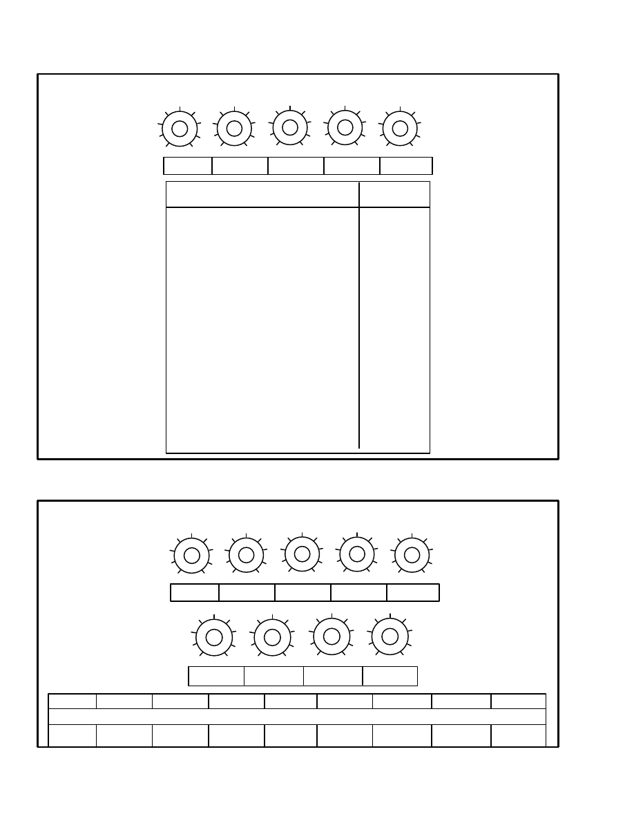
EV–100 MOTOR CONTROLLER ADJUSTMENTS
1
9
5
1
9
5
1
9
5
1
9
5
1
9
5
1
9
5
1
9
5
1
9
5
1
9
5
CREEP
C/A
C/L
1A TIME
PLUG
REGEN C/L REGEN D.O.
F.W.P.U.
F.W.D.O.
CREEP
C/A
C/L
1A TIME
PLUG
REGEN C/L REGEN D.O.
F.W.P.U.
F.W.D.O.
E1.25–1.75XL (E25–35XL) (36–48 volts with Regenerative Braking)
5
3
*
7
4
3.5
––
9
235 amp***
500 amp**
E1.25–1.75XL (E25–35XL) (36–48 volts with Plugging only)
5
4
*
4
4
––
235 amp***
500 amp**
––
––
––
6
7
*
4
1
3.5
7
8
9
235 amp***
500 amp**
450 amp***
6
4
*
4
2
––
––
––
235 amp***
500 amp**
6
4
4
4
2
3.5
––
––
9
250 amp***
475 amp**
E/J2.00–3.00XL (E/J40–60XL) (36–48 volts with Regenerative Braking)
E/J2.00–3.00XL (E/J40–60XL) (36–48 volts with Plugging only)
E/J2.00–3.00XL (E/J40–60XL) (72–80 volts with Regenerative Braking)
E/J2.00–3.00XL (E/J40–60XL) (72–80 volts with Plugging only)
1.4 sec
1.7 sec
185 amp***
350 amp**
8
5
4
4
5
––
––
––
250 amp***
1.8 sec
300 amp***
––
475 amp**
2.0 sec
1.0 sec
1.3 sec
350 amp**
J25–35B (24 volts)
––
––
6
2
*
5
5
––
––
––
235 amp***
500 amp**
––
J25–35B (36 volts)
4
2
*
5
5
––
––
––
235 amp***
500 amp**
––
* Control cards made before August 1986 and marked 099 must be set to a C/L of 9.
Control cards made after August 1986 and marked 098 must be set to a C/L of 5.
** Maximum current must be checked with the ammeter shunt in the armature circuit.
*** Maximum current must be checked with the ammeter shunt in the battery circuit.
TABLE 5. CONTROL CARD ADJUSTMENTS FOR THE TRACTION MOTOR CIRCUIT
7
7
8
4
1
6
––
––
245 amp***
4
475 amp**
1.0 sec
0.55 sec
430 amp***
E3.50–4.00XL (E70–80XL) Not available on E4.50–5.50XL (E100–120XL) models
0.7 sec
1.3 sec
16
1
9
5
1
9
5
1
9
5
1
9
5
1
9
5
1A TIME
SPD 1
SPD 2
SPD 3
NOT USED
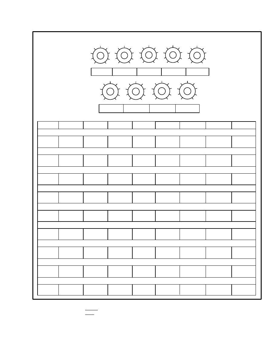
EV–100 MOTOR CONTROLLER ADJUSTMENTS
VOLTS
E1.25–1.75XL (E25–35XL) 36–48 volts
(open center)
SPEED 1 (Tilt)
SPEED 2 (Lift)
SPEED 3
C/A (300 milliseconds)
17
24
not used
E/J2.00–3.00XL (E/J40–60XL) 36–48 volts
SPEED 1 (Tilt)
SPEED 2 (Lift)
SPEED 3
3.5 (17 v)
3.5 (24 v)
not used
set to 6 on adj.
1A TIME
not used
C/A (300 milliseconds) set to 6 on adj.
1A TIME
not used
E/J2.00–3.00XL (E/J40–60XL) 72–80 volts
SPEED 1 (Tilt)
SPEED 2 (Lift)
SPEED 3
3 (40 v)
4 (50 v)
not used
C/A (300 milliseconds) set to 6 on adj.
1A TIME
not used
E3.50–5.50XL (E70–120XL) 36–48 volts
TABLE 6. CONTROL CARD ADJUSTMENTS FOR THE PUMP MOTOR CIRCUIT
SPEED 1
SPEED 2 (Tilt)
SPEED 3 (Lift)
C/A (300 milliseconds)
1A TIME
1 (0 v)
4.5 (24 v)
9 Full On)
set to 6 on adj.
not used
LIFT TRUCK MODEL AND ADJUSTMENTS
1
9
5
1
9
5
1
9
5
1
9
5
1
9
5
1
9
5
1
9
5
1
9
5
1
9
5
CREEP
C/A
C/L
1A TIME
PLUG
REGEN C/L REGEN D.O.
F.W.P.U.
F.W.D.O.
EV–200 MOTOR CONTROLLER ADJUSTMENTS
CREEP
C/A
C/L
1A TIME
PLUG
REGEN C/L REGEN D.O.
F.W.P.U.
F.W.D.O.
E3.50–4.00XL (E70–80XL)
7
5.5
4
4
5
5
4
6
4.5
220 amp*
1.4 sec
435 amp*
1.0 sec
3%
470 amp*
* Maximum current must be checked with the ammeter shunt in the battery circuit.
TABLE 7. CONTROL CARD ADJUSTMENTS FOR THE TRACTION MOTOR CIRCUIT
17
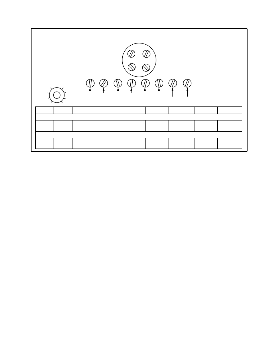
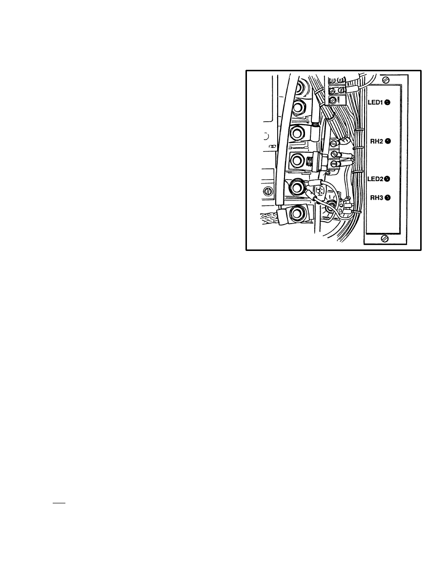
PROPORTIONAL CONTROL
(J25–35A Only) (See FIGURE 9.)
This adjustment calibrates the proportional control of
the logic circuit with the position of the steering potenti-
ometer on J25–35A units. The signal voltage from the
steering potentiometer indicates the angle position of
the steering trunnion. The logic circuit uses this voltage
signal to control the energy applied to the traction mo-
tors. This adjustment is not normally necessary unless
the steering potentiometer or the logic circuit is re-
placed.
NOTE: You will see other adjustments on the propor-
tional control module. Special equipment is needed to
make these adjustments. Make changes only to the ad-
justments described in this section.
Before making this adjustment, make sure the steering
potentiometer is calibrated with the steering trunnion.
See the section of the steering potentiometer on page 19.
Make sure the steering chain is correctly adjusted.
1. Make sure the battery is charged and has a specific
gravity of at least 1.260.
2. Raise the drive wheels from the floor.
NOTE: Do not push on the accelerator (MONOTROL)
pedal during Steps 3, 4 and 5.
3. Connect the battery and turn the key switch to the
“ON” position. Close the seat switch. If there is a direc-
tion switch on the steering column, put the switch in the
neutral position. Put the steering trunnion in the straight
forward position (see page 19). Adjust the steering po-
tentiometer until the LED 1 is illuminated.
4. Rotate the steering wheel for turning with a minimum
radius towards the right (85 degrees from the straight
forward position).
NOTE: The 85 degree point for turning in a minimum
radius must occur as you steer into the turn. This point is
where you will adjust to 100% reverse power of the in-
ner drive wheel. The clearance in the steering assembly
will give a wrong 85 degree indication if you go past 85
degrees and return. Make the adjustment when steering
into the turn.
The maximum turning angle of the trunnion is approxi-
mately 90 degrees when the lift truck is moving. The
trunnion will only turn approximately 85 degrees when
the lift truck is stopped because of the increased friction
between the floor and the tire.
FIGURE 9. PROPORTIONAL CONTROL
ADJUSTMENTS
9499
Adjust RH 2 until LED 2 illuminates. If LED 2 is already
illuminated, turn RH 2 counterclockwise until LED 2 is
not illuminated. Then turn RH 2 clockwise until LED 2
just illuminates.
5. Rotate the steering wheel for turning with a minimum
radius towards the left (85 degrees). Check that LED 2
just illuminates at the same degree as when the steering
was turned towards the right. If the adjustment is not
correct, check again the calibration of the steering trun-
nion with the steering potentiometer. Also, check Step 3
again.
6. Check the “CREEP” speed adjustment. Put the steer-
ing trunnion in the straight ahead position. Check that
both drive wheels rotate at equal “CREEP” speeds. Ad-
just the “CREEP” speeds so that they are equal.
7. When turning the lift truck, the proportional control
has a “CREEP” speed that overrides the logic card
“CREEP” speed. This adjustment is RH 3 on the propor-
tional control module. This adjustment is set at the fac-
tory and is not normally adjusted by service technicians.
If this adjustment is not correct, the controller can have a
PMT when turning the lift truck.
If RH 3 must be adjusted, do the following:

18
The drive wheels are raised from the floor. Operate the
lift truck at “CREEP” speed. Turn the steering trunnion
for a right turn until you hear the “FORWARD” and
“REVERSE” contactors reverse positions. Turn RH 3
until the right drive wheel just stops. RH 3 controls the
“CREEP” speed of both right and left turns at the point
where the contactors reverse positions. Turn the steering
trunnion for a left turn until you hear the “FORWARD”
and “REVERSE” contactors reverse positions. Check
that the left drive wheel has stopped. If the left drive
wheel does not stop, there is an error in the adjustments
described earlier.
8. Check the operation of the proportional control. Put
the steering in the straight forward position. Push on the
accelerator (MONOTROL) pedal until the traction mo-
tors operate at approximately half speed. Turn the steer-
ing to the right direction until the right drive wheel stops
at approximately 73 degrees. See the right drive wheel
increase in speed as the steering is turned farther in the
right direction. The right drive wheel will now turn in
the opposite direction from the left drive wheels. Turn
the steering to the right to the limit. The right drive
wheel will now turn at the same speed as the left drive
wheel, but in the opposite direction. Turn the steering to
the left direction and make the same checks.
SCR CONTROL, DUAL HYDRAULIC
PUMP MOTORS
An EV–100 SCR controller is used in lift trucks that
have dual hydraulic pump motors. One motor is oper-
ated by the SCR controller, the other motor is operated
by a contactor. This system provides three speeds.
The EV–100 control card for the dual hydraulic pump
motors is not the same as the control card for the traction
circuit. The SCR function of a speed control is the same,
but the many functions necessary for control of a trac-
tion circuit are not needed for the hydraulic pump opera-
tion. A contactor is not used in the power circuit. Each of
the hydraulic pump motors has a 325 ampere fuse.
This control card does not have an SRO check or a PMT
check. If SCR 1 has a short–circuit, the pump motor will
run until the battery is disconnected. The main control
valve is an open center valve and the hydraulic function
will stop when the hand lever is returned to the NEU-
TRAL position. The SCR controller controls the motors
to provide three speeds:
Speed 1 is for the TILT function and for auxiliary func-
tions that require the third or fourth spool of the main
control valve. The SCR controlled motor operates at
about half speed.
Speed 2 is for the low speed LIFT function and second
speed on third function (third function has two speeds).
The SCR controlled hydraulic pump motor operates at
full speed.
Speed 3 is only for the high speed LIFT function. Both
hydraulic pump motors operate at full speed. The Speed
3 function is the only time that the contactor controlled
motor operates.
The control card sends three reference voltages to the
switches controlled by the linkage to the main control
valve. When a contact on a switch is closed, the refer-
ence voltage is connected with battery negative and the
control card senses the change in the reference voltage.
The voltage controlled oscillator in the control card
causes the SCR 1 to operate at a certain frequency. The
speeds of operation can be adjusted by the control card
adjustments as shown in TABLE 2. through TABLE 7.
SCR CONTROL, SINGLE PUMP MOTOR
Connect a voltmeter so that the voltage can be measured
across the hydraulic motor. Some service persons con-
nect the (+) probe of the voltmeter to the cable connec-
tion for D3 and the (–) probe to the P10 cable from the
pump motor.
Move the TILT hand lever so that the pump motor oper-
ates at low speed and measure the voltage. If the voltage
is not according to the specifications (see TABLE 2.
through TABLE 7.), adjust the voltage by turning the
SPD 2 potentiometer. Do not make voltage measure-
ments when the pump motor is operating against the re-
lief valve.
Move the LIFT hand lever so that the pump motor oper-
ates at speed 2 and measure the voltage. If the voltage is
not according to the specifications, adjust the voltage by
turning the SPD 3 potentiometer. Do not make voltage
measurements when the pump motor is operating
against the relief valve.
NOTE: The adjustment SPD 3 is always set full “ON”.
The adjustment of SPD 1 is always set full “OFF”. Ad-
justment to a voltage for SPD 1 and 3 is not required.
19
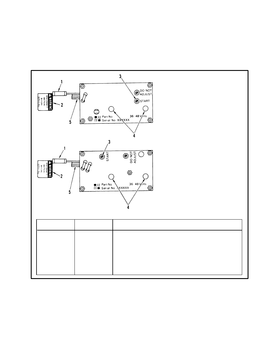
Accelerator Card
(E20–100B, J40–60AS Only)
(See FIGURE 10. and FIGURE 11.)
There are two parts to the accelerator circuit on the
E20–100B and J40–60AS units: accelerator potenti-
ometer and the accelerator card. The accelerator poten-
tiometer must be correctly adjusted before adjusting the
accelerator card.
The accelerator card is a solid–state circuit that senses
the control voltages at the control switches and the ac-
celerator potentiometer. When the sequence of voltages
is correct, the accelerator card sends a control voltage
through the direction switch to close a direction contac-
tor.
FIGURE 10. ACCELERATOR CARD
1. CARD FUSE
2. WARNING TAG
3. “START” ADJUSTMENT
4. MOUNT HOLES
5. CONTROL WIRES (SEE TABLE)
CONTROL WIRES
WIRE NUMBER
(With Seat Brake)
WIRE NUMBER
(With Seat Brake)
FUNCTION
7
13
15
20
29
38
45
–
10
13
15
20
29
38
45
7
71
Battery Voltage Through Card Fuse
Suppressor Circuit Connected To Battery
Battery Voltage To Direction Switch Negative
Battery Voltage
Accelerator Potentiometer
Brake Switch
Causes Control Card To Begin “1A Time”
Battery Voltage To Power Steering, Hourmeter
Input Voltage From Seat Switch
E20–100B
EARLIER PRODUCTION
LATER PRODUCTION
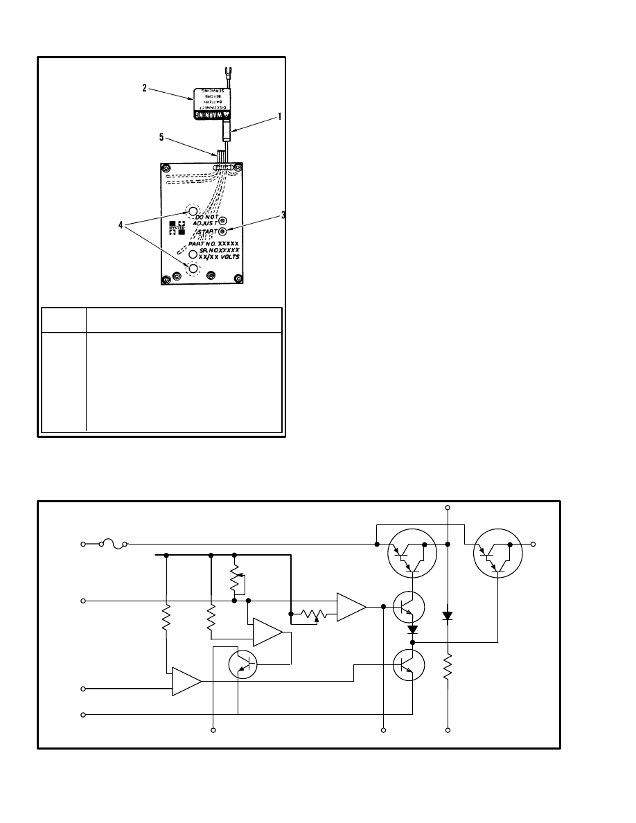
20
1. CARD FUSE
2. WARNING TAG
3. START
ADJUSTMENT
4. HOLES FOR
FASTENING
5. CONTROL WIRES
(SEE TABLE)
FIGURE 11. ACCELERATOR CARD
J40–60AS
10410
WIRE
NUMBER
FUNCTION
10
Battery voltage through card fuse
13
Suppressor circuit connected to battery
15
Battery voltage to direction switch negative
20
Battery negative
29
Accelerator potentiometer
38
Brake switch
45
Causes control card to begin “1A TIME”
7
Battery voltage to power steering, hourmeter
71
Input voltage from seat switch
Circuit Description For Accelerator Card
Used With A Seat Switch (See FIGURE 12.)
The circuit board has three integrated circuits that oper-
ate like switches. IC1, IC2, and IC3 compare an input
voltage with a reference voltage. When the input volt-
age decreases to the reference voltage level, the output
voltage changes from “high” to “low”. This voltage
change from “high” to “low” causes a transistor to go
“ON”.
Transistor Q1 is a switch that controls “1A TIME”.
Transistor Q2 controls the operation of transistor Q5
which supplies battery voltage to the power steering
through wire 7. Transistor Q3 controls the operation of
Q4 which supplies battery voltage to the direction
switch through wire 15. Transistors Q2 and Q3 must
both be “ON” before Q4 can be “ON”. Q5 will be “ON”
when Q2 is “ON”.
The circuit board has its own regulated power supply
which is shown on the schematic (see FIGURE 12.) as
B+. Resistors between the B+ and one input of the inte-
grated circuits give the reference voltages.
Wire 10. Battery voltage to the accelerator card.
Wire 13. Connected to battery negative. Function is a
suppressor circuit for electrical noise.
Wire 20. Battery negative to the accelerator card.
Wire 71. Input from the seat switch causes the voltage
output from IC1 to go “low” and causes Q2 to go “ON”.
FIGURE 12. FUNCTION SCHEMATIC FOR ACCELERATOR CARD (SEAT SWITCH)
–
+
–
+
–
+
10555
WIRE 7
WIRE 15
WIRE 13
WIRE 38
WIRE 45
WIRE 10
WIRE 29
WIRE 71
WIRE 20
B+
+
DO NOT
ADJUST
IC2
IC3
IC1
Q1
Q2
Q3
Q4
Q5
START
21
Wire 29. The accelerator potentiometer decreases the
voltage on wire 29 from a high of 4.0–4.5 volts to a low
of 0.0–0.2 volts. This decreasing voltage controls two
functions in the accelerator card:
•
“START” (IC3)
•
“1A TIME” (IC2)
Accelerator “START” (IC3)
The control card supplies 4.8–5.0 volts at R5 when no
accelerator circuit is connected. When the accelerator
potentiometer is adjusted correctly, the voltage at R5 is
4.0–4.5 volts. When the accelerator (MONOTROL)
pedal is pushed, the voltage at R5 decreases. This de-
creasing voltage is sensed on wire 29. When this voltage
is 3.6–3.8 volts, the output voltage of IC3 goes “low”
and causes transistor Q3 to go “ON”. If transistor Q2 is
also “ON”, transistor Q4 will supply battery voltage
through wire 15 to the direction switch. The “START”
adjustment controls the comparison voltage when IC3
causes transistor Q1 to go “ON”.
Accelerator “1A TIME” (IC2)
When the voltage on wire 29 decreases to 0.4–0.8 volt,
the output voltage of IC2 goes “low” and causes transis-
tor Q1 to go “ON”. Transistor Q1 decreases the voltage
in wire 45 to zero.
Wire 45. The control card supplies 8.0 volts at R6. When
transistor Q1 decreases the voltage at R6 to zero, the
control card begins “1A TIME”.
Wire 38. The output of IC3 is electrically the same point
as wire 38. When the brake switch is closed, battery
negative is connected at the base of transistor Q1. This
action stops the signal from IC3 and causes Q1 to go
“OFF”. Battery negative on wire 38 stops the battery
voltage to the direction switch.
Wire 7. Battery voltage to the accelerator card.
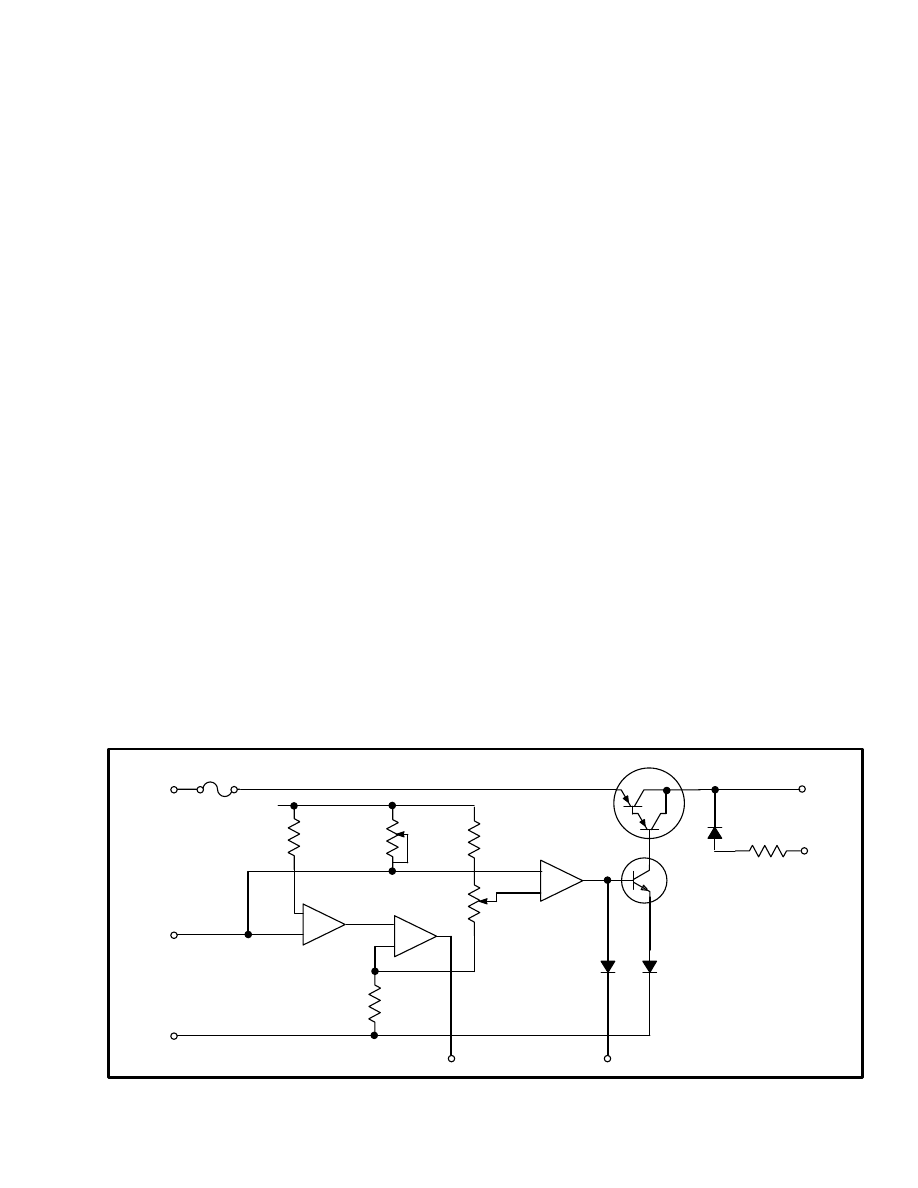
Circuit Description For Accelerator Card
Used With A Seat Brake (See FIGURE 13.)
This circuit board also has three integrated circuits that
operate like switches. IC1, IC2, and IC3 compare an in-
put voltage with a reference voltage. When the input
voltage decreases to the reference voltage level, the out-
put voltage changes from “high” to “low”. This voltage
change from “high” to “low” causes a transistor to go
“ON” or another Wire 20. Battery negative to the accel-
erator card. Also the negative for the circuit in the accel-
erator card.
Wire 29. The accelerator potentiometer decreases the
voltage on wire 29 from a high of 4.0–4.5 volts to a low
of 0.0–0.2 volts. This decreasing voltage controls two
functions in the accelerator card:
•
“START” (IC3)
•
“1A TIME” (IC1 and IC2)
integrated circuit to also change. Transistor Q1 is a
switch that controls the operation of transistor Q2.
FIGURE 13. FUNCTION SCHEMATIC FOR ACCELERATOR CARD (SEAT BRAKE)
–
+
–
+
–
+
10555
WIRE 15
WIRE 13
WIRE 38
WIRE 45
WIRE 7
WIRE 29
WIRE 20
B+
+
DO NOT
ADJUST
IC2
IC3
IC1
Q1
Q2
START
–

22
The circuit board has its own regulated power supply
which is shown on the schematic (see FIGURE 13.) as
B+. Resistors between the B+ and one input of the inte-
grated circuits give the reference voltages.
Accelerator “START” (IC3)
The control card supplies 4.8–5.0 volts at R5 when no
accelerator circuit is connected. When the accelerator
potentiometer is adjusted correctly, the voltage at R5 is
4.0–4.5 volts. When the accelerator (MONOTROL)
pedal is pushed, the voltage at R5 decreases. This de-
creasing voltage is sensed on wire 29. When this voltage
is 3.6–3.8 volts, the output voltage of IC3 goes “low”
and causes transistor Q1 to go “ON”. Q1 causes Q2 to go
“ON” and supply battery voltage through wire 15 to the
direction switch. The “START” adjustment controls the
comparison voltage when IC3 causes transistor Q1 to go
“ON”.
Accelerator “1A TIME” (IC1 and IC2)
When the voltage on wire 29 decreases to 0.4–0.8 volt,
the output voltage of IC1 goes “low” and causes the out-
put voltage of IC2 (wire 45) to go “low”. IC2 decreases
the voltage in wire 45 to zero.
Wire 45. The control card supplies 8.0 volts at R6. When
IC2 decreases the voltage at R6 to zero, the control card
begins “1A TIME”.
Wire 38. The output voltage of IC3 is electrically the
same point as wire 38. When the brake switch is closed,
battery negative is connected at the base of transistor
Q1. This action stops the signal from IC3 and causes Q1
to go “OFF”. Battery negative on wire 38 stops the bat-
tery voltage to the direction switch.
CHECK THE ACCELERATOR CARD
The accelerator potentiometer must be correctly ad-
justed before making voltage checks on the accelerator
card. See the Adjustments section.
1. Check the fuse to the accelerator card. If the fuse is
bad, check the accelerator card and the coils for the di-
rection contactor for a short–circuit.
CAUTION
A short circuit between wire 15 and battery negative
will damage the accelerator card before the fuse can
protect the circuit.
Disconnect wire 15 from the accelerator card to the ter-
minal strip. Set the controls to operate the lift truck. If
the fuse goes bad again, replace the accelerator card.
2. If the fuse is good, set the controls to operate in the
“REVERSE” direction and push on the accelerator
(MONOTROL) pedal. Check for approximately battery
voltage between wire 15 and battery negative. If there is
no battery voltage on wire 15, check that the brake
switch is open. If the brake switch is correct, replace the
accelerator card.
3. If the lift truck operates when the accelerator
(MONOTROL) pedal is pushed, raise the accelerator to
the UP position. If the voltage on wire 15 does not de-
crease to 0 volts, replace the accelerator card.
ADJUSTING THE ACCELERATOR CARD
Only the “START” adjustment is required for the accel-
erator card. The “START” adjustment sets the compari-
son voltage for IC3. IC3 causes the transistors to go ON”
and send the control voltage to the direction switch.
The “DO NOT ADJUST” sets the reference voltage for
IC3. The reference voltage is set at the factory and must
not be changed.
1. Make sure the accelerator potentiometer is adjusted
correctly. Raise the drive wheels.
2. Connect the voltmeter to R5 and battery negative.
Make sure the accelerator or MONOTROL pedal is
NOT moved.
3. Close the key switch, parking brake switch and the
seat switch. Set the “START” adjustment at a voltmeter
indication of 4.0 to 4.5 volts. The direction contactors
must close when the pedal is moved 10 to 13 mm (
3
/
8
to
1
/
2
in).
THE POTENTIOMETERS AND CONTROL
SWITCHES
Steering Potentiometer (J25–35A Only)
(See FIGURE 14. And FIGURE 15.)
The correct operation of the steering potentiometer is
necessary for the correct proportional control of each
traction motor. The purpose of this instruction is for the
following:
•
Describe how to calibrate the steering
potentiometer with the steering trunnion.
23
1. BATTERY COMPARTMENT PLATE
2. FRAME BEARING PLATE
3. STEERING TIRE
4. TRUNNION SUPPORT
5. SQUARE
FIGURE 14. ALIGNMENT OF THE STEERING
POTENTIOMETER
6468
5
4
1
2
3
•
Check the condition of the steering
potentiometer.
You will need a Cir/Kit meter or an ohmmeter and a tool
called a square.
1. Align the steering trunnion so that the lift truck will
move forward in a straight direction. Use a square to
make sure that steering trunnion is aligned. The trun-
nion support must be parallel to the leg of the square as
shown in FIGURE 14. Turn the key switch to the “ON”
position. Check that the red light (light emitting diode
LED 1) is illuminated on the proportional control mod-
ule.
If the LED 1 is not illuminated, open the cover to the bat-
tery compartment.
WARNING
Put a cover over the battery to prevent short–circuits
with tools and materials.
1. POTENTIOMETER HOUSING
2. HOSE COUPLING WITH UPPER
AND LOWER CLAMPS
3. STEERING TRUNNION SPINDLE
4. CONNECTOR TERMINALS
FIGURE 15. STEERING POTENTIOMETER
1
4
2
3
9047
Loosen the lower hose clamp of the coupling. See
FIGURE 15. Rotate the coupling until the red light LED
1 is illuminated. Tighten the hose clamp. Check again
that LED 1 is still illuminated.
The steering potentiometer is now calibrated with the
steering trunnion when the lift truck moves forward in a
straight direction.
2. Check the condition of the steering potentiometer if
necessary. Check that the voltage between terminals 8
and 9 of the proportional control card is 5.0 volts. Con-
nect the probes of the voltmeter to terminals 10 and 9.
Rotate the steering trunnion. The correct voltage will
make a smooth variation from 1.0 to 4.0 volts. The
straight “FORWARD” or “REVERSE” position is 2.5
volts.
To make a resistance check, disconnect the connector
for the steering potentiometer. Connect an ohmmeter (R
X 100 scale) between the connector terminals 1 and 3.
The correct resistance is approximately 4800 – 6000
ohms. Connect the ohmmeter between the connector
terminals 1 and 2 or 2 and 3. Loosen the lower hose
clamp of the coupling. Slowly rotate the shaft of the po-
tentiometer and look at the ohmmeter. The resistance is
variable between 0 and 5000 ohms. If the potentiometer
is in good condition, the resistance will increase or de-
crease SMOOTHLY between the limits as the shaft is
24
turned. Replace the steering potentiometer if the correct
resistance is not indicated or the change is not smooth.
NOTE: If you replace the accelerator or steering poten-
tiometer, make sure you use the correct part number.
Both potentiometers look the same and have more than
300
_
mechanical rotation. The accelerator potentiome-
ter has approximately 70
_
electrical rotation and the
steering potentiometer has approximately 290
_
electri-
cal rotation.
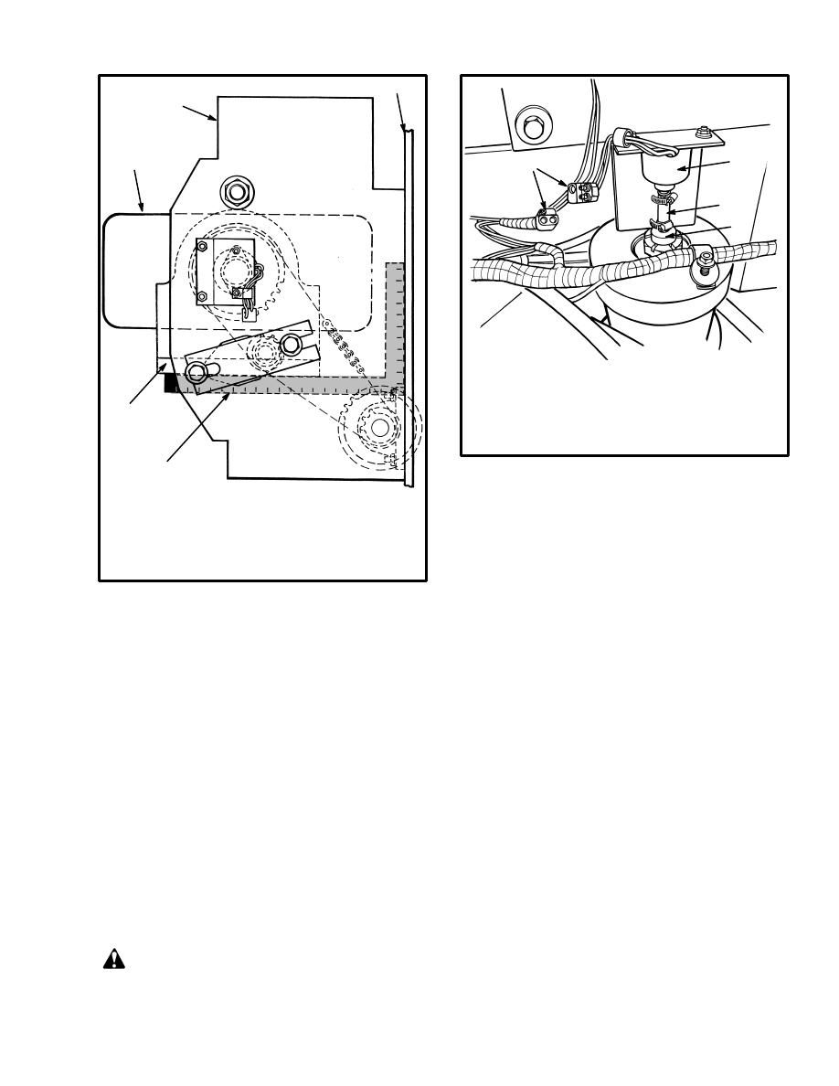
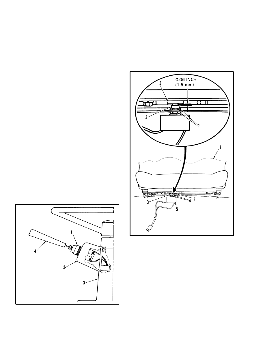
Accelerator Potentiometer And Start Switch
(E20–120XL And J25–60XL Only)
(See FIGURE 16.)
NOTE: Adjustment of the accelerator linkage will
make necessary the adjustment of the “START” switch.
1. ACCELERATOR (MONOTROL)
PEDAL
2. SPRING
3. PIVOT CAPSCREW
4. CRANK
5. POTENTIOMETER HOUSING
6. POTENTIOMETER SHAFT
7. START SWITCH*
8. PEDAL STOP
FIGURE 16. ACCELERATOR POTENTIOMETER AND START SWITCH ADJUSTMENT
E20–120XL AND J25–60XL ONLY
1.5 mm SHIM
(0.06 in)
7
8
11570
A
B
C
10 mm (0.4 in) SHIM
1. Rotate the potentiometer housing to the end of the mount slots as shown in the illustration.
2. Loosen the crank on the shaft of the accelerator potentiometer. Push the accelerator (MONOTROL) pedal
down and install a 10 mm (0.40 in) shim between the pedal and the mount bracket (see illustration). Adjust
the shaft of the accelerator potentiometer so that the resistance between terminals B and C is 100–200 ohms
(R x 1 scale). Tighten the crank on the potentiometer shaft and check the resistance again.
3. Loosen the bolt that holds the pedal stop. Raise the pedal to the pedal stop. Install a 1.5 mm (0.06 in) shim
between the pedal and the pedal stop. Adjust the pedal stop so that the resistance between terminals B and
C is 4100–4300 ohms (R x 100) scale). Tighten the bolt that holds the pedal stop and check the resistance
again.
4. Adjust the position of the START switch* so that it will actuate when the 1.5 mm (0.06 in) shim is in position
between the pedal and the pedal stop.
1
2
3
4
6
5
7
25
The accelerator potentiometer has a range of 0–6000
ohms. If you must replace an accelerator potentiometer,
make sure you use the correct part number. Many poten-
tiometers have approximately 290
_
mechanical rota-
tion, but the accelerator potentiometer has approxi-
mately 70
_
electrical rotation. The accelerator potenti-
ometer is connected to the accelerator pedal.
The start switch is only used on units without a
MONOTROL pedal. The start switch and accelerator
potentiometer must be adjusted together. Adjust the ac-
celerator potentiometer and start switch as shown in
FIGURE 16.
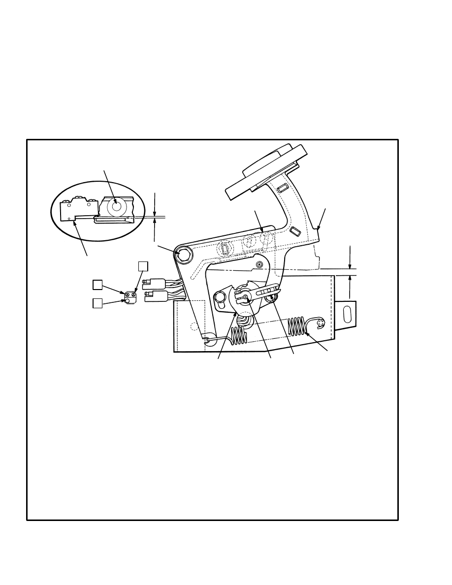
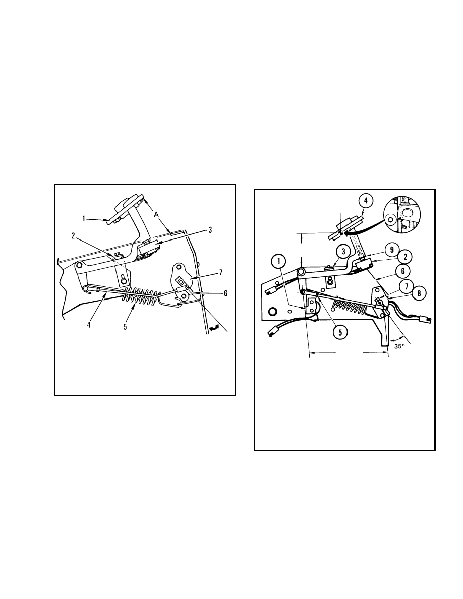
1. MONOTROL PEDAL
2. PEDAL STOP
3. DIRECTION SWITCH
4. ACCELERATOR LINKAGE
5. SPRING
6. CRANK
7. POTENTIOMETER HOUSING
FIGURE 17. MONOTROL PEDAL AND SWITCH
ADJUSTMENT (E20–120B)
10556
A = E60–120B
10.6cm (4.16 in)
OTHER MODELS
11.5 cm (4.5 in)
Accelerator Potentiometer And Direction
Switch (See FIGURE 17. and FIGURE 18.)
The accelerator potentiometer sends a voltage signal to
the control logic for speed and acceleration. A correct
accelerator (MONOTROL) linkage is necessary before
adjusting the accelerator potentiometer.
The direction switch sends a signal to the motor control-
ler to close the “FORWARD” and “REVERSE” contac-
tors.
1. Check and adjust the accelerator linkage.
a. Disconnect the battery and separate the
connector. Remove the center floor plate. Make
sure the link length for J25–35A units is as shown
in FIGURE 18. If necessary, disconnect the link
from the crank and adjust to the correct length. A
minimum of two threads must be engaged at the
end of the link.
b Check the distance between the frame and the
pedal stop to give the correct distance as shown in
FIGURE 17. or FIGURE 18. If necessary, adjust
the pedal stop to give the correct distance for your
lift truck model.
1. “START” SWITCH
2. “FORWARD” AND “REVERSE” SWITCH
3. PEDAL STOP, UP
4. ACCELERATOR (MONOTROL)
5. JAM NUT
6. PART OF FRAME
7. CRANK
8. CONNECTOR
9. LOCK NUT
FIGURE 18. MONOTROL PEDAL ASSEMBLY
(J25–35A)
10410
9.65 cm
(3.80 in)
23.5 cm
(9.25 in)
(ROD LENGTH
2. Check and adjust the accelerator potentiometer. Con-
nect the battery. Measure the voltage between wire 29
(+) and wire 20 (–) when the pedal is pushed just enough
to close the “START” switch. The correct voltage is 3.5
to 4.0 volts at “CREEP” speed. Push the pedal fully
down. The voltage will decrease smoothly to less than
0.5 volts. The typical voltage for maximum speed is 0.2

26
volts. Adjust the accelerator potentiometer within the
limits.
NOTE: The floor plates must be installed to check the
maximum speed adjustment of the accelerator potenti-
ometer. The floor plates can be set in position temporar-
ily without installing the bolts.
To check or adjust the accelerator potentiometer using a
resistance indication, disconnect wire 29 from terminal
3. Push the accelerator (MONOTROL) pedal to the
floor plate. Measure the resistance between wire 29 and
terminal 5. Loosen the clamp screw on the crank and ad-
just the potentiometer to 200 ohms or less. Tighten the
clamp screw. When the pedal is in the up position, the
correct resistance is 4800–6000 ohms. Connect wire 29
to terminal 3.
3. Check the adjustment of the direction switch by push-
ing on the “FORWARD” pad of the MONOTROL pedal
using your hand. If the switch is correctly adjusted, you
will hear the switch close before the pad is fully in the
“FORWARD” position. If the switch is not actuated be-
fore the pedal begins to move down, go to Step 4.
4. If the direction switch is adjusted or replaced. make an
identification of the three wires and disconnect them
from the switch. Loosen the lock nut on the direction
switch. Hold the pad of the MONOTROL pedal in the
“REVERSE” position. Rotate the direction switch into
the pedal until you hear the direction switch close. Ro-
tate the switch out of the pedal
1
/
2
to 2 rotations. Align
the switch as shown in FIGURE 17. or FIGURE 18.
Tighten the lock nut. Check the adjustment as described
in Step 3. The switch must open and the pedal pad must
return to the “REVERSE” direction when you remove
your hand. When the adjustment is complete, connect
the wires to the switch.
Adjusting Start Switch (See FIGURE 18.)
NOTE: The START switch is used on some earlier pro-
duction lift trucks and on lift trucks that have the op-
tional “FORWARD” and “REVERSE” switch on the
steering column.
The START switch is a small switch fastened to the
mount for the pedal assembly. See FIGURE 18. The
START switch is normally open. The accelerator
(MONOTROL) pedal actuates the START switch using
a leaf spring. The “START” switch prevents the opera-
tion of the lift truck until the SRO circuit is complete.
The START switch must be adjusted so that the switch is
open when the accelerator (MONOTROL) pedal is in
the up position. The adjustment of the “START” switch
must be checked after adjustments are made to the accel-
erator linkage.
Measure the space from the top pedal stop to the arm of
the pedal. Adjust the “START” switch so that it closes
when the space is greater than 2 mm (0.075 in). The
“START” switch opens correctly when the space is less
than 0.75 mm (0.030 in).
Check the switch with an ohmmeter. Disconnect the bat-
tery and separate the connector. A good switch will indi-
cate less than 50 ohms between the terminals “NC” and
“COM” with the switch closed.
“FORWARD” And “REVERSE” Switch
(MONOTROL) (Earlier Production Lift Trucks)
(See FIGURE 17. and FIGURE 18.)
NOTE: Earlier production lift trucks have a FOR-
WARD and REVERSE switch in the housing of the
MONOTROL pedal arm. Later units use two switches,
one under each pad of the MONOTROL pedal.
NOTE: The numbers in () are item numbers of
FIGURE 18.
1. Disconnect the battery and separate the connector.
Remove the center floor plate. Push on the “FOR-
WARD” pad (4) with your hand. If the switch adjust-
ment is correct, you will hear the switch close before the
pad (4) is fully in the “FORWARD” position. If the
switch is not actuated before the pedal begins to move
down, go to Step 2.
2. If the switch is adjusted or replaced, make an identifi-
cation of the three wires and disconnect them from the
switch. Loosen the lock nut (9) on the switch (2). Hold
the pad (4) in the “REVERSE” position with your hand.
Rotate the switch into the pedal until you can hear the
switch close. Rotate the switch out of the pedal 1/2–2 ro-
tations. Align the switch as shown in FIGURE 17.
Tighten the lock nut (9). Check the switch adjustment as
in Step 1. The switch must open and the pad (4) must re-
turn to the “REVERSE” direction when you remove
your hand. When the adjustment is complete, connect
the wires to the switch. Install the floor plate.
27
11571
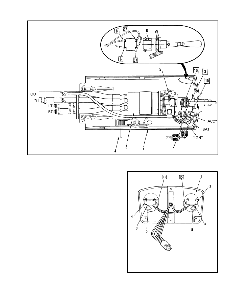
1. KEY SWITCH
2. STEERING COLUMN
3. STEERING CONTROL UNIT
4. POSITION ADJUSTMENT
5. HORN SWITCH
6. OPTIONAL FWD–REV LEVER
FIGURE 19. STEERING COLUMN ASSEMBLY FOR SitDrive
LIFT TRUCKS
Direction Switches (MONOTROL)
(Later Production Lift Trucks)
(See FIGURE 20.)
There is a small direction switch under each pad of the
MONOTROL pedal. See FIGURE 20. Each switch
controls one direction. A capacitor is in parallel with
each direction switch to decrease arcs at the switch con-
tacts. If both sides of the MONOTROL pedal are pushed
at the same time, the direction circuit is deenergized and
the lift truck will not move. The contacts of the two di-
rection switches are in a series and parallel arrangement
so that both direction contactors can not be energized at
the same time.
Each direction switch must be adjusted so that one set of
switch contacts are closed when the pedal pad is at each
position of its travel. The pedal pad must be removed
from the pedal assembly to make adjustments. Each
switch is normally adjusted so that the body of the
switch is even with the stop on the pedal pad.
11568
FIGURE 20. MONOTROL PEDAL
1. PEDAL PAD
2. FORWARD DIRECTION SWITCH
3. CAPACITOR
4. REVERSE DIRECTION SWITCH
5. SPRING
28
NOTE: The direction switches used in the
MONOTROL pedal are made for Hyster Company with
a special contact clearance and timing. Other switches
made by the manufacturer are in the same case and will
fit in the same space in the MONOTROL pedal. Use
only replacement switches with a Hyster part number.
Other switches that are similar in design will fit, but the
contacts will often burn and not give good service.
“FORWARD” And “REVERSE” Switch (Steer-
ing Column)
(See FIGURE 19. And FIGURE 21.)
The controller includes logic circuits for an optional
“FORWARD” and “REVERSE” switch on the steering
column. See FIGURE 19.
The direction switch com-
pletes the circuit for battery voltage to the FORWARD
or REVERSE contactors. This switch is not adjustable.
A bad switch must be replaced. Remove the cover of the
steering column so that you can disconnect wires 6 an 8
from the switch. The switch can be checked with an
ohmmeter. Disconnect the battery. Measure between
wire 8 and wire 83. A good switch will indicate less than
50 ohms when the control is in the “REVERSE” posi-
tion. Measure between wire 6 and wire 83. A good
switch will indicate less than 50 ohms when the control
is in the “FORWARD” position. Replace a bad switch
and reconnect the wires. Install the cover for the steering
column.
1. “FORWARD” AND
“REVERSE” SWITCH
2. SWITCH HOUSING
3. STEERING COLUMN
4. HANDLE
FIGURE 21. “FORWARD” AND “REVERSE”
SWITCH (STEERING COLUMN)
9048
Hydraulic Pump Switch
See the section on THE MAIN CONTROL VALVE.
Replace The Key Switch (See FIGURE 19.)
Replace a bad key switch. Remove the cover for the
steering column. Disconnect wires 3 and 10 and replace
the key switch. Connect the wires and install the cover.
1. SEAT
2. PLATE
3. SWITCH BARREL
4. JAM NUTS
5. SWITCH
FIGURE 22. SEAT SWITCH ADJUSTMENT FOR
LIFT TRUCKS WITH A SEAT BRAKE
8567
Adjust The Seat Switch (See FIGURE 22.)
1. The standard seat switch has no adjustments. It can be
checked with an ohmmeter. The correct resistance is less
than 50 ohms when the seat switch is closed.
2. Lift trucks equipped with an optional seat brake have
a seat switch installed as shown in FIGURE 22. This
seat switch has a higher current rating than the standard
seat switch.
Adjust the jam nuts (4) to move the switch. adjust the
switch so that there is 1.5 mm (0.06 in) clearance be-
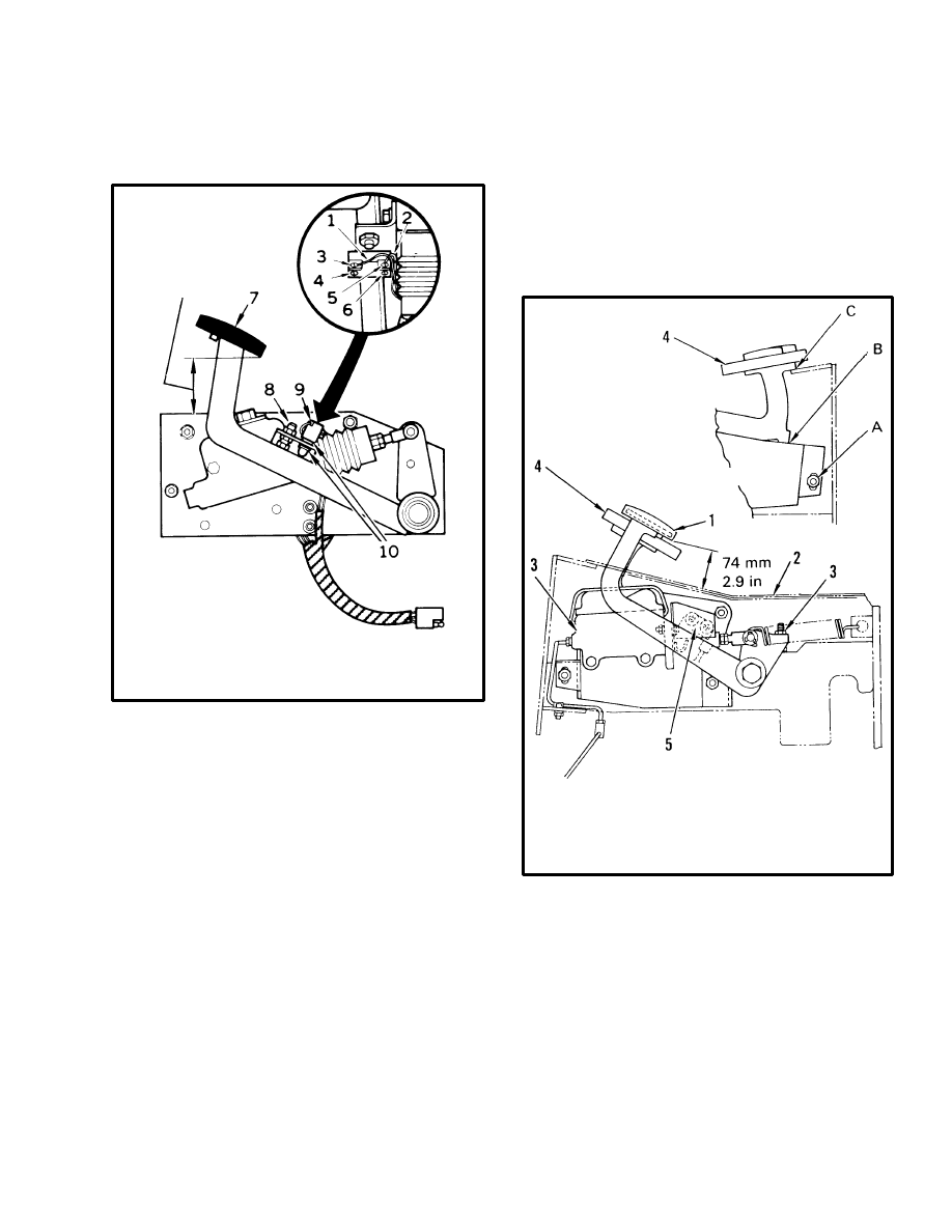
29
tween the switch barrel and the plate (2) as shown in
FIGURE 22.
1. WIRE 35
2. WIRE 15
3. NO TERMINAL
4. NC TERMINAL
5. NO TERMINAL
6. NC TERMINAL
7. BRAKE PEDAL
8. PEDAL STOP
FIGURE 23. BRAKE SWITCH ADJUSTMENT
6469
79.2 +3.0
–6.4
mm
(3.12
+0.12
–0.25
in)
9. BRAKE SWITCH
10. SWITCH ADJUSTMENT
LOCK NUTS
Adjust The Brake Switch (See FIGURE 23.)
NOTE: The brake switch is not used in electric lift
trucks manufactured after November 1986.
The brake switch is a small switch fastened to the mount
for the pedal assembly. See FIGURE 22. The brake
switch is held closed when the brake pedal is in the up
position. When the brake pedal is pushed down, the
brake switch opens. The brake switch interrupts the coil
circuit for the “FORWARD” and “REVERSE” contac-
tors. This action prevents the traction motors from
working against the brakes.
If the brake switch is correctly adjusted, you can hear the
switch open within the first 13 mm (0.5 in) of brake
pedal movement. If necessary to adjust the brake switch,
loosen the two lock nuts for the switch. Adjust the height
of the switch in the bracket with the two lock nuts for the
switch. The switch can be checked with an ohmmeter.
The correct resistance is less than 50 ohms when the
switch is closed. Adjust the brake pedal as shown in
FIGURE 24. or FIGURE 25.
11569
FIGURE 24. BRAKE AND ACCELERATOR
PEDAL ADJUSTMENT (E/J25–60XL)
1. BRAKE PEDAL ASSEMBLY
2. FLOOR PLATES
3. STOP ADJUSTMENT, BRAKE PEDAL
4. ACCELERATOR (MONOTROL) PEDAL
5. BRAKE SWITCH
ADJUST MOUNT “A”
SO THAT THE
ACCELERATOR
PEDAL STOPS AT
“B” AND “C”
(MONOTROL)
Parking Brake Switch (See FIGURE 26.)
The parking brake switch of the E60–120B units is on
the actuator link under the battery compartment. See
FIGURE 26. The parking brake switch must be adjusted
so that the switch is actuated when the parking brake is
applied.
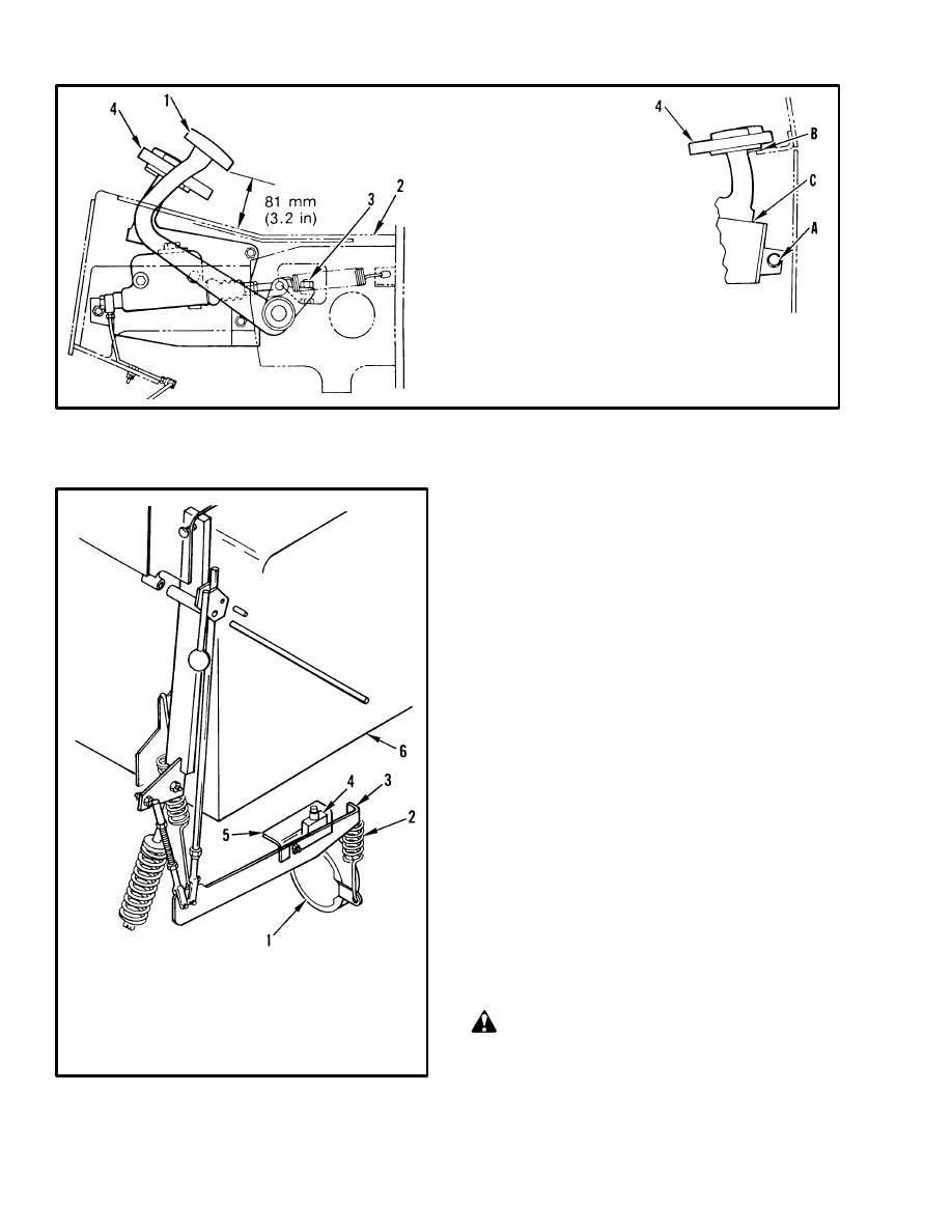
30
FIGURE 25. BRAKE AND ACCELERATOR PEDAL ADJUSTMENT (E70–120XL)
1. BRAKE PEDAL ASSEMBLY
2. FLOOR PLATES
3. STOP ADJUSTMENT, BRAKE PEDAL
4. ACCELERATOR (MONOTROL) PEDAL
12353
ADJUST MOUNT “A”
SO THAT WHEN THE
ACCELERATOR (MONOTROL)
PEDAL STOPS AT “B”
THERE IS 1.0–4.0 mm
(0.04–0.16 in) CLEARANCE
AT “C”
FIGURE 26. PARKING BRAKE SWITCH
(E60–120B)
1. PARKING BRAKE ASSEMBLY
2. SPRING
3. LEVER
4. PARKING BRAKE SWITCH
5. SHIELD
6. BOTTOM OF BATTERY COMPARTMENT
10320
Rocker Switch (See FIGURE 27.)
Rocker switches are usually mounted to an instrument
panel. Access to the back of the panel or switch mount-
ing surface is required to replace the switch. Replace a
switch as described in the following paragraphs.
1. Make sure the key switch is in the OFF position.
2. Put tags on the switch wires, or wire harness for cor-
rect identification during installation. Remove the wires
from the switch terminals.
3. Use a flat tip screw driver or other suitable tool and
press in on the retainer clips at each side of the switch.
Remove the switch from the face of the instrument panel
or switch mounting surface while holding the retainer
clips in the “released” position.
4. Remove the switch and install the replacement switch
in the panel. Make sure the switch is in the correct posi-
tion for reading by the operator.
5. Connect the wires, or wire harness to the electrical ter-
minals on the switch.
CAUTION
Make sure wire connectors do not touch the other
switch or meter terminal wire connectors, metal
brackets or the bracket mounting nuts. Make sure
there is no tension or binding on the wires or connec-
tors.
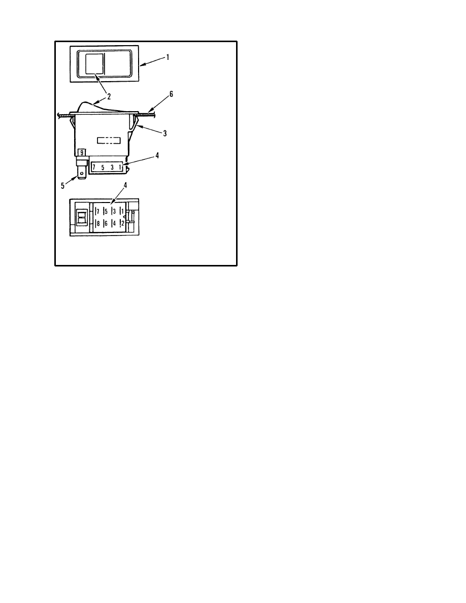
31
FIGURE 27. ROCKER SWITCH
1. SWITCH ASSEMBLY
2. LENS AND
FUNCTION
SYMBOL
3. RETAINER CLIP
4. ELECTRICAL
SERVICE
TERMINALS
5. ELECTRICAL
POWER TERMINALS
6. INSTRUMENT PANEL
13284
HYDRAULIC PUMP SOFT START
(E100–120B Only) (72/80 Volt Only)
The 72–80 volt E4.50–5.50B (E100–120B) models
have a soft start system for the hydraulic pump motor. In
addition to the contactor for the motor, the circuit in-
cludes a resistor, a resistor by–pass contactor (PR), and a
time delay. See the section DIAGRAMS – E60–120B,
8000 SRM 229.
When the hoist/tilt switch energizes the contactor for the
hydraulic pump motor, current flows through the resis-
tor and the pump motor. The resistor reduces the current
load through the contactor as the contactor starts the mo-
tor. After an interval of 0.09–0.12 of a second, the time
delay closes the by–pass contactor (PR). This function
directly connects the battery and the motor.
The by–pass contactor and the contactor for the pump
motor are the same type. See Contactor Repair in the
section EV–1W MOTOR CONTROLLER, 2200
SRM 409. A defective time delay must be replaced.
Document Outline
- ELECTRICAL CHECKS AND ADJUSTMENTS FOR SitDrive) ELECTRICAL LIFT TRUCKS
- GENERAL
- CONTROL AND POWER FUSES
- CONTROL CARD ADJUSTMENTS
- Adjusting Creep Speed, "CREEP'
- Adjusting Controlled Acceleration, "C/A"
- Adjusting Current Limit, "C/L"
- Adjust "1A TIME"
- Adjust 1A Drop Out, "1A D.O"
- Adjust Plugging, "PLUG"
- Ramp Start
- Adjust Field Weakening Pick Up and Drop Out, "F.W.P.U." And "F.W.D.O."
- Adjust "REGEN C/L" (Current Limit)
- Adjust "REGEN D.O." (Drop Out)
- PROPORTIONAL CONTROL (J25-35A Only)
- SCR CONTROL, DUAL HYDRAULIC PUMP MOTORS
- SCR CONTROL, SINGLE PUMP MOTOR
- Accelerator Card (E-20-100B, J40-60AS Only)
- Circuit Description For Accelerator Card Used With A Seat Switch
- Accelerator "START" (IC3)
- Accelertor "1A TIME" (IC2)
- Circuit Description For Accelerator Card Used With A Seat Brake
- Accelerator "START" (IC3)
- Accelerator "1A TIME" (IC1 and IC2)
- CHECK THE ACCELERTOR CARD
- ADJUSTING THE ACCELERATOR CARD
- THE POTENTIOMETERS AND CONTOL SWITCHES
- Steering Potentiometer (J25-35A Only)
- Accelerator Potentiometer And Start Switch (E20-120XL And J25-60XL Only)
- Accelerator Potentiometer And Direction Switch
- Adjusting Start Switch
- "FORWARD" And "REVERSE" Switch (MONOTROL) (Earlier Production Lift Trucks)
- Direction Switches (MONOTROL) (Later Production Lift Trucks)
- "FORWARD" And "REVERSE" Switch (Steering Column)
- Hydraulic Pump Switch
- Replace The Key Switch
- Adjust The Seat Switch
- Adjust The Brake Switch
- Parking Brake Switch
- Rocker Switch
- HYDRAULIC PUMP SOFT START (E100-120B Only) (72/80 Volt Only)
Wyszukiwarka
Podobne podstrony:
897070 2200SRM0288 (01 1994) UK EN
897435 2200SRM0473 (03 1994) UK EN
897856 2200SRM0612 (01 1996) UK EN
897495 2200SRM0514 (01 2004) UK EN
1564268 2200SRM1106 (01 2004) UK EN
1595265 2200SRM1204 (01 2005) UK EN
1556871 2200SRM1105 (01 2004) UK EN
897844 2200SRM0603 (01 1996) UK EN
897844 2200SRM0603 (01 1996) UK EN
1564283 1900SRM1107 (01 2004) UK EN
1452929 2200SRM0679 (11 2003) UK EN
więcej podobnych podstron