FRAME
E/J1.25-1.75XL (E25-35XL) [C114];
E/J2.00-3.00XL (E/J40-60XL) [C108, B168];
E3.50-5.50XL (E70-120XL, E70-120XL3) [C098]
PART NO. 897066
100 SRM 284

SAFETY PRECAUTIONS
MAINTENANCE AND REPAIR
• When lifting parts or assemblies, make sure all slings, chains, or cables are correctly
fastened, and that the load being lifted is balanced. Make sure the crane, cables, and
chains have the capacity to support the weight of the load.
• Do not lift heavy parts by hand, use a lifting mechanism.
• Wear safety glasses.
• DISCONNECT THE BATTERY CONNECTOR before doing any maintenance or repair
on electric lift trucks.
• Disconnect the battery ground cable on internal combustion lift trucks.
• Always use correct blocks to prevent the unit from rolling or falling. See HOW TO PUT
THE LIFT TRUCK ON BLOCKS in the Operating Manual or the Periodic Mainte-
nance section.
• Keep the unit clean and the working area clean and orderly.
• Use the correct tools for the job.
• Keep the tools clean and in good condition.
• Always use HYSTER APPROVED parts when making repairs. Replacement parts
must meet or exceed the specifications of the original equipment manufacturer.
• Make sure all nuts, bolts, snap rings, and other fastening devices are removed before
using force to remove parts.
• Always fasten a DO NOT OPERATE tag to the controls of the unit when making repairs,
or if the unit needs repairs.
• Be sure to follow the WARNING and CAUTION notes in the instructions.
• Gasoline, Liquid Petroleum Gas (LPG), Compressed Natural Gas (CNG), and Diesel fuel
are flammable. Be sure to follow the necessary safety precautions when handling these
fuels and when working on these fuel systems.
• Batteries generate flammable gas when they are being charged. Keep fire and sparks
away from the area. Make sure the area is well ventilated.
NOTE:
The following symbols and words indicate safety information in this
manual:
WARNING
Indicates a condition that can cause immediate death or injury!
CAUTION
Indicates a condition that can cause property damage!

Frame
Table of Contents
TABLE OF CONTENTS
General ...............................................................................................................................................................
Description .........................................................................................................................................................
Overhead Guard Repair ....................................................................................................................................
Remove ...........................................................................................................................................................
Install .............................................................................................................................................................
Battery Restraint and Seat Assembly Repair ..................................................................................................
Seat Brake Assembly E/J1.25-3.00XL (E/J25-60XL), Adjust......................................................................
Seat Brake Assembly E3.50-5.50XL (E70-120XL), Adjust..........................................................................
Counterweight Repair .......................................................................................................................................
Remove ...........................................................................................................................................................
Install .............................................................................................................................................................
Traction Motor Repair .......................................................................................................................................
Remove ...........................................................................................................................................................
Install .............................................................................................................................................................
Hydraulic Tank Repair ......................................................................................................................................
Inspect ............................................................................................................................................................
Small Leaks, Repair ......................................................................................................................................
Large Leaks, Repair ......................................................................................................................................
Clean ..............................................................................................................................................................
Steam Method............................................................................................................................................
Chemical Solution Method........................................................................................................................
Additional Preparations For Repair .............................................................................................................
Painting Instructions.........................................................................................................................................
Safety Label Replacement .................................................................................................................................
This section is for the following models:
E/J1.25-1.75XL (E25-35XL) [C114];
E/J2.00-3.00XL (E/J40-60XL) [C108, B168];
E3.50-5.50XL (E70-120XL, E70-120XL3) [C098]
©2002 HYSTER COMPANY
i

"THE
QUALITY
KEEPERS"
HYSTER
APPROVED
PARTS
100 SRM 284
Description
General
This section has a description and the service procedures for the parts of the frame. These parts include the
frame, counterweight assembly, overhead guard, hydraulic tank, access panels, and label positions. See Fig-
ure 1. The procedure for removing the traction motor is also described in this section.
Description
The frame is a single weldment.
The frame has
mounts for the counterweight, overhead guard,
tilt cylinders, steering axle, and drive axle as-
sembly.
See Figure 1.
The hydraulic tank is a
plastic tank mounted in the right side of the frame
on all of the XL series of lift trucks except the
E3.50-5.50XL (E70-120XL, E70-120XL
3
) series. On
the E3.50-5.50XL (E70-120XL, E70-120XL
3
) models,
the hydraulic tank is part of the lift truck frame and
is a welded steel unit. The lift trucks must have a
hood over the battery, or a covered battery if a hood
is not installed.
The floor plates can be removed
for access to the hydraulic systems. A panel in the
bottom of the battery compartment can be removed
for access to the traction motor and the hydraulic
pump motor.
On the E3.50-5.50XL (E70-120XL,
E70-120XL
3
) models, this panel also gives access
to the power steering pump motor. The SCR (sil-
icon controlled rectifier) electronic controller and
contactors are in the counterweight. A panel in the
counterweight can be removed for access to the SCR
controller and contactors.
NOTE: E1.75XL (E35XL) UNIT SHOWN.
1.
OVERHEAD GUARD
2.
COUNTERWEIGHT
3.
STEERING AXLE AND
WHEELS
4.
PARKING BRAKE LEVER
5.
FRAME
6.
DRIVE AXLE AND WHEELS
7.
UPRIGHT
8.
FORKS
9.
CARRIAGE
10. LOAD BACKREST EXTENSION
11. ACCESS PANEL TO SCR
ELECTRONIC CONTROLLER
Figure 1. Lift Truck Parts
1

Description
100 SRM 284
The frames for the lift trucks are similar in design,
but are different sizes for each XL series.
The
J1.25-1.75XL (E25-35XL) models with pneumatic
tires have fenders welded to the frame because of
the wider drive tires.
The E2.00-3.00XL (E40-60XL) lift trucks have
frames made in four different configurations. The
lift truck with the long (842 mm battery compart-
ment) frame has a larger battery compartment than
the lift truck with the short (695 mm battery com-
partment) frame. Some lift trucks have additional
counterweight metal added to the frame in front
of the steering axle because of differences in some
battery weights. The remainder of the frame parts
are the same.
The J2.00-3.00XL (J40-60XL) models are made with
two sizes of frames. A short frame (842 mm bat-
tery compartment) is available for the J2.00-2.50XL
(J40-50XL) models. A long frame (1010 mm battery
compartment) is available for all of the J2.00-3.00XL
(J40-60XL) models. The size of the battery compart-
ment and battery size specifications are shown in Ta-
ble 1, Table 2, andTable 3.
The E3.50-5.50XL (E70-120XL, E70-120XL
3
) models
are made with two sizes of frames. A short frame
(1018 mm battery compartment) is available for
the E3.50-4.00XL (E70-80XL) and the E5.00XLS
(E100XLS) models. A long frame (1183 mm battery
compartment) is available for the E5.00-5.50XL
(E100-120XL, E70-120XL
3
) models. The size of the
battery compartment and battery size specifications
are shown in Table 1, Table 2, Table 3, and Table 4.
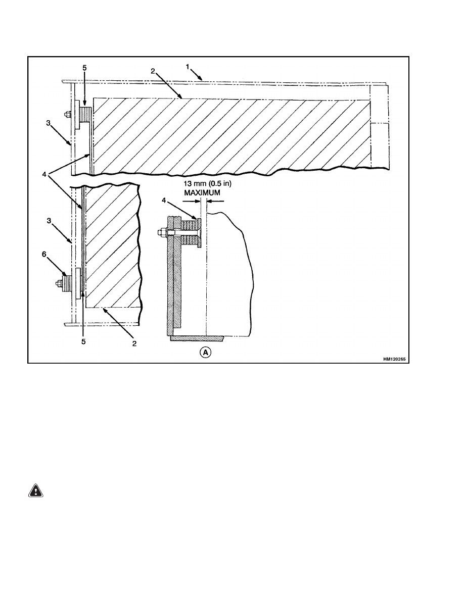
The lift trucks are equipped with adjustable spac-
ers in the battery compartment. See Figure 2. Add
or remove shims from under the front spacer bar to
control the movement of the battery in the forward
and backward directions. Install an equal number of
shims at each capscrew. Install the additional shims
under the nuts of the capscrews (outside battery com-
partment). The spacers on each side of the battery
can be adjusted to control the movement of the bat-
tery from side to side. Access to the nuts for the spac-
ers for the sides of the battery is under the frame near
the steer tires on all units. Tighten all capscrews. It
can be necessary to install the side spacers facing the
opposite direction for some batteries. If the spacers
cannot be adjusted for a battery that is specified for
this lift truck, see your Hyster lift truck dealer for
the correct spacers.
NOTE: Maximum tolerances are +0 and
13 mm (+0
and
0.5 in.) for the size of the battery compartment.
The battery specification chart shows the maximum
size tolerances that will permit a battery to still fit
into a battery compartment.
WARNING
The battery must fit the battery compartment
so that the battery restraint system will oper-
ate correctly. Use spacers to prevent the bat-
tery from moving more than 13 mm (0.5 in.) in
any horizontal direction.
The weight of the battery is a large part of the coun-
terweight system on an electric lift truck. Make sure
that the battery is within the weight limits indicated
on the nameplate. Each model of lift truck has a
cast-iron counterweight that provides the additional
weight necessary for the indicated capacity. A slot in
the overhead guard permits removal of the battery
without removing the overhead guard.
2
100 SRM 284
Description
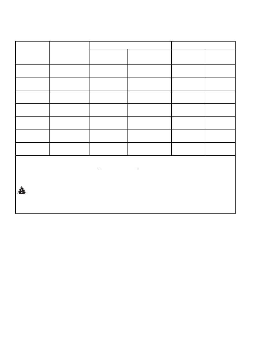
Table 1. Battery Specifications (Battery without Cover)
Battery Size Min./Max.
Weight
Model
Minimum
Compartment
Size Length ×
Width
Length
Width
Min.
Max.
E1.25XL
(E25XL)
694 × 909 mm
(27.3 × 35.8 in.)
654 to 692 mm
(25.8 to 27.2 in.)
784 to 885 mm
(30.9 to 34.8 in.)
794 kg
(1749 lb)
1132 kg
(2493 lb)
E1.50XL
(E30XL)
694 × 909 mm
(27.3 × 35.8 in.)
654 to 692 mm
(25.8 to 27.2 in.)
784 to 885 mm
(30.9 to 34.8 in.)
839 kg
(1848 lb)
1132 kg
(2493 lb)
E1.75XL
(E35XL)
694 × 909 mm
(27.3 × 35.8 in.)
654 to 692 mm
(25.8 to 27.2 in.)
784 to 885 mm
(30.9 to 34.8 in.)
917 kg
(2020 lb)
1132 kg
(2493 lb)
E2.00-2.50XL
(E40-50XL)
694 × 987 mm
(27.3 × 38.9 in.)
681 to 692 mm
(26.8 to 27.2 in.)
978 to 983 mm
(38.5 to 38.7 in.)
1045 kg
(2302 lb)
1450 kg
(3195 lb)
E2.00-3.00XL
(E40-60XL)
841 × 987 mm
(33.1 × 38.9 in.)
800 to 838 mm
(31.5 to 32.9 in.)
978 to 983 mm
(38.5 to 38.7 in.)
1315 kg
(2896 lb)
1750 kg
(3855 lb)
E3.50-4.00XL
(E70-80XL)
993 × 1146 mm
(39.3 × 45.1 in.)
950 to 1117 mm
(37.4 to 43.9 in.)
950 to 990 mm
(37.4 to 38.9 in.)
1542 kg
(3396 lb)
2400 kg
(5286 lb)
E5.00XL
(E100XLS)
993 × 1146 mm
(39.3 × 45.1 in.)
950 to 1117 mm
(37.4 to 43.9 in.)
950 to 990 mm
(37.4 to 38.9 in.)
1633 kg
(3597 lb)
2400 kg
(5286 lb)
E5.00XL
(E100XL)
1153 × 1146 mm
(45.9 × 45.1 in.)
950 to 1117 mm
(37.4 to 43.9 in.)
1115 to 1150 mm
(43.9 to 45.3 in.)
1814 kg
(3996 lb)
2700 kg
(5947 lb)
E5.50XL
(E120XL)
1153 × 1146 mm
(45.9 × 45.1 in.)
950 to 1117 mm
(37.4 to 43.9 in.)
1115 to 1150 mm
(43.9 to 45.3 in.)
1919 kg
(4227 lb)
2700 kg
(5947 lb)
J2.00-2.50XL
(J40-50XL)
842 × 987 mm
(33.1 × 38.9 in.)
800 to 838 mm
(31.5 to 32.9 in.)
978 to 983 mm
(38.5 to 38.7 in.)
1315 kg
(2896 lb)
1750 kg
(3855 lb)
J2.00-3.00XL
(J40-60XL)
1010 × 987 mm
(39.8 × 38.9 in.)
968 to 991 mm
(38.1 to 39.0 in.)
978 to 983 mm
(38.5 to 38.7 in.)
1550 kg
(3417 lb)
2060 kg
(4537 lb)
585 mm (23.0 in.) = maximum height for batteries without a cover used in lift trucks with a hood.
NOTE:
Maximum tolerances are +0 and
13 mm (+0 and
0.5 in.) for the size of the battery compartment.
The battery specification chart shows the maximum size tolerances that will permit the battery to still fit into
a battery compartment.
WARNING
The battery must fit the battery compartment so that the battery restraint system will operate
correctly. Use the spacers designed by Hyster Company to prevent the battery from moving more
than 13 mm (0.5 in.) in any horizontal direction.
3

Description
100 SRM 284
Table 2. Battery Specifications (Battery with Flat Cover)
Battery Size Min./Max.
Weight
Model
Minimum
Compartment
Size Length ×
Width
Length
Width
Min.
Max.
E1.25XL
(E25XL)
694 × 909 mm
(27.3 × 35.8 in.)
654 to 692 mm
(25.8 to 27.2 in.)
784 to 907 mm
(30.9 to 35.7 in.)
794 kg
(1749 lb)
1285 kg
(2830 lb)
E1.50XL
(E30XL)
694 × 909 mm
(27.3 × 35.8 in.)
654 to 692 mm
(25.8 to 27.2 in.)
784 to 907 mm
(30.9 to 35.7 in.)
839 kg
(1848 lb)
1285 kg
(2830 lb)
E1.75XL
(E35XL)
694 × 909 mm
(27.3 × 35.8 in.)
654 to 692 mm
(25.8 to 27.2 in.)
784 to 907 mm
(30.9 to 35.7 in.)
917 kg
(2020 lb)
1285 kg
(2830 lb)
E2.00-2.50XL
(E40-50XL)
36/48V
694 × 987 mm
(27.3 × 38.9 in.)
681 to 691 mm
(26.8 to 27.2 in.)
978 to 983 mm
(38.5 to 38.7 in.)
1045 kg
(2300 lb)
1450 kg
(3197 lb)
E2.00-3.00XL
(E40-60XL)
36/48V
841 × 987 mm
(33.1 × 38.9 in.)
800 to 838 mm
(31.5 to 32.9 in.)
978 to 983 mm
(38.5 to 38.7 in.)
1315 kg
(2900 lb)
1750 kg
(3855 lb)
E2.00-2.50XL
(E40-50XL)
72/80V
694 × 1037 mm
(27.3 × 40.8 in.)
681 to 691 mm
(27.0 to 27.2 in.)
1029 to 1034 mm
(40.5 to 40.7 in.)
935 kg
(2059 lb)
1270 kg
(2797 lb)
E2.00-3.00XL
(E40-60XL)
72/80V
841 × 1037 mm
(33.1 × 40.8 in.)
833 to 838 mm
(32.8 to 32.9 in.)
1029 to 1034 mm
(40.5 to 40.7 in.)
1420 kg
(3128 lb)
1690 kg
(3722 lb)
E3.50-4.00XL
(E70-80XL)
993 × 1146 mm
(39.3 × 45.1 in.)
950 to 990 mm
(37.4 to 39.0 in.)
950 to 1143 mm
(37.4 to 45.0 in.)
1542 kg
(3396 lb)
2400 kg
(5286 lb)
E5.00XLS
(E100XLS)
993 × 1146 mm
(39.3 × 45.1 in.)
950 to 990 mm
(37.4 to 39.0 in.)
950 to 1143 mm
(37.4 to 45.0 in.)
1633 kg
(3597 lb)
2400 kg
(5286 lb)
E5.00XL
(E100XL)
1153 × 1146 mm
(45.9 × 45.1 in.)
1115 to 1150 mm
(43.9 to 45.3 in.)
950 to 1143 mm
(37.4 to 45.0 in.)
1814 kg
(3996 lb)
2700 kg
(5947 lb)
E5.50XL
(E120XL)
1153 × 1146 mm
(45.9 × 45.1 in.)
1115 to 1150 mm
(43.9 to 45.3 in.)
950 to 1143 mm
(37.4 to 45.0 in.)
1919 kg
(4227 lb)
2700 kg
(5947 lb)
J2.00-2.50XL
(J40-50XL)
36/48V
841 × 987 mm
(33.1 × 38.9 in.)
800 to 838 mm
(31.5 to 32.9 in.)
978 to 983 mm
(38.5 to 38.7 in.)
1315 kg
(2900 lb)
1750 kg
(3855 lb)
617 mm (24.3 in.) = maximum height for batteries with a flat cover used in lift trucks without a hood.
NOTE:
Maximum tolerances are +0 and
13 mm (+0 and
0.5 in.) for the size of the battery compartment.
The battery specification chart shows the maximum size tolerances that will permit the battery to still fit into
a battery compartment.
WARNING
The battery must fit the battery compartment so that the battery restraint system will operate
correctly. Use the spacers designed by Hyster Company to prevent the battery from moving more
than 13 mm (0.5 in.) in any horizontal direction.
4
100 SRM 284
Description
Table 2. Battery Specifications (Battery with Flat Cover) (Continued)
Battery Size Min./Max.
Weight
Model
Minimum
Compartment
Size Length ×
Width
Length
Width
Min.
Max.
J2.00-3.00XL
(J40-60XL)
36/48V
1009 × 987 mm
(39.7 × 38.9 in.)
968 to 991 mm
(38.1 to 39.0 in.)
978 to 983 mm
(38.5 to 38.7 in.)
1550 kg
(3414 lb)
2060 kg
(4537 lb)
J2.00-2.50XL
(J40-50XL)
72/80V
841 × 1037 mm
(33.1 × 40.8 in.)
833 to 838 mm
(32.8 to 32.9 in.)
1029 to 1034 mm
(40.5 to 40.7 in.)
1420 kg
(3128 lb)
1690 kg
(3722 lb)
J2.00-3.00XL
(J40-60XL)
72/80V
1009 × 1037 mm
(39.7 × 40.8 in.)
1001 to 1006 mm
(39.4 to 39.6 in.)
1029 to 1034 mm
(40.5 to 40.7 in.)
1600 kg
(3524 lb)
1850 kg
(4075 lb)
617 mm (24.3 in.) = maximum height for batteries with a flat cover used in lift trucks without a hood.
NOTE:
Maximum tolerances are +0 and
13 mm (+0 and
0.5 in.) for the size of the battery compartment.
The battery specification chart shows the maximum size tolerances that will permit the battery to still fit into
a battery compartment.
WARNING
The battery must fit the battery compartment so that the battery restraint system will operate
correctly. Use the spacers designed by Hyster Company to prevent the battery from moving more
than 13 mm (0.5 in.) in any horizontal direction.
5
Description
100 SRM 284
Table 3. Battery Specifications (Battery with Dome Cover)
Battery Size Min./Max.
Weight
Model
Minimum
Compartment
Size Length ×
Width
Length
Width
Min.
Max.
E1.25XL
(E25XL)
694 × 909 mm
(27.3 × 35.8 in.)
686 to 691 mm
(27.0 to 27.2 in.)
890 to 895 mm
(35.0 to 35.2 in.)
794 kg
(1750 lb)
1285 kg
(2830 lb)
E1.50XL
(E30XL)
694 × 909 mm
(27.3 × 35.8 in.)
686 to 691 mm
(27.0 to 27.2 in.)
890 to 895 mm
(35.0 to 35.2 in.)
839 kg
(1850 lb)
1285 kg
(2830 lb)
E1.75XL
(E35XL)
694 × 909 mm
(27.3 × 35.8 in.)
686 to 691 mm
(27.0 to 27.2 in.)
890 to 895 mm
(35.0 to 35.2 in.)
917 kg
(2020 lb)
1285 kg
(2830 lb)
E2.00-2.50XL
(E40-50XL)
694 × 1037 mm
(27.3 × 40.8 in.)
686 to 691 mm
(27.0 to 27.2 in.)
1029 to 1034 mm
(40.5 to 40.7 in.)
935 kg
(2059 lb)
1270 kg
(2797 lb)
E2.50-3.00XL
(E50-60XL)
841 × 1037 mm
(33.1 × 40.8 in.)
833 to 838 mm
(32.8 to 33.0 in.)
1029 to 1034 mm
(40.5 to 40.7 in.)
1420 kg
(3128 lb)
1690 kg
(3722 lb)
J2.00-2.50XL
(J40-50XL)
841 × 1037 mm
(33.1 × 40.8 in.)
833 to 838 mm
(32.8 to 32.9 in.)
1029 to 1034 mm
(40.5 to 40.7 in.)
1420 kg
(3128 lb)
1690 kg
(3722 lb)
J2.00-3.00XL
(J40-60XL)
1009 × 1037 mm
(39.7 × 40.8 in.)
1001 to 1006 mm
(39.4 to 39.6 in.)
1029 to 1034 mm
(40.5 to 40.7 in.)
1600 kg
(3524 lb)
1850 kg
(4075 lb)
612 mm (24.1 in.) = maximum height for batteries with a dome cover used in lift trucks without a hood.
NOTE:
Maximum tolerances are +0 and
13 mm (+0 and
0.5 in.) for the size of the battery compartment.
The battery specification chart shows the maximum size tolerances that will permit the battery to still fit into
a battery compartment.
WARNING
The battery must fit the battery compartment so that the battery restraint system will operate
correctly. Use the spacers designed by Hyster Company to prevent the battery from moving more
than 13 mm (0.5 in.) in any horizontal direction.
6

100 SRM 284
Description
Table 4. Battery Specifications*
Battery Length
Weight
Model
VOLTS
Minimum
Compartment
Size Length ×
Width
Min./Max
Min.
Max.
E3.50-4.00XL
(E70-80XL
3
)
36
841 x 987 mm
(33.1 x 38.9 in.)
950 to 990 mm (37.4
to 39.0 in.)
1542 kg
(3400 lb)
2400 kg
(5292 lb)
E5.00XL
(E100XL
3
S)
36
841 x 987 mm
(33.1 x 38.9 in.)
950 to 990 mm (37.4
to 39.0 in.)
1633 kg
(3600 lb)
2400 kg
(5292 lb)
E5.00XL
(E100XL
3
)
36
694 x 10376 mm
(27.3 x 40.8 in.)
1115 to 1150 mm
(43.9 to 45.3 in.)
1814 kg
(4000 lb)
2700 kg
(5954 lb)
E5.50XL
(E120XL
3
)
36
993 x 1146 mm
(39.3 x 45.1 in.)
1115 to 1150 mm
(43.9 to 45.3 in.)
1919 kg
(4231 lb)
2700 kg
(5954 lb)
E3.50-4.00XL
(E70-80XL
3
)
48
841 x 987 mm
(33.1 x 38.9 in.)
950 to 990 mm (37.4
to 39.0 in.)
1542 kg
(3400 lb)
2400 kg
(5292 lb)
E5.00XL
(E100XL
3
S)
48
841 x 987 mm
(33.1 to 38.9 in.)
950 to 990 mm (37.4
to 39.0 in.)
1633 kg
(3600 lb)
2400 kg
(5292 lb)
E5.00XL
(E100XL
3
)
48
694 x 1037 mm
(27.3 x 40.8 in.)
1115 to 1150 mm
(43.9 to 45.3 in.)
1814 kg
(4000 lb)
2700 kg
(5954 lb)
E5.50XL
(E120XL
3
)
48
993 x 1146 mm
(39.3 x 45.1 in.)
1115 to 1150 mm
(43.9 to 45.3 in.)
1919 kg
(4231 lb)
2700 kg
(5954 lb)
*BATTERY WIDTH
Batteries without cover: 950 to 1117 mm (37.4 to 44.0 in.)
Batteries with cover: 950 to 1143 mm (37.4 to 45.0 in.)
NOTE:
Maximum tolerances are +0 and -13 mm (+0 and -0.5 in.) for the size of the battery compartment. The
battery specification chart shows the maximum size tolerances that will permit the battery to still fit into a
battery compartment.
7
Overhead Guard Repair
100 SRM 284
A. FRONT SPACER
1.
BATTERY COMPARTMENT
2.
BATTERY
3.
BULKHEAD
4.
SPACER BAR
5.
SHIM
6.
STORE ADDITIONAL SHIMS IN FRONT OF
BULKHEAD
Figure 2. Battery Compartment Shims
Overhead Guard Repair
REMOVE
WARNING
Do not operate the lift truck without the over-
head guard correctly fastened to the lift truck.
1.
Remove battery as described in the section Peri-
odic Maintenance for your lift truck.
2.
Access to capscrews that hold rear supports of
overhead guard to counterweight is from the bat-
tery compartment. Remove capscrews.
3.
Remove two capscrews that hold each front sup-
port of overhead guard to cowl. Disconnect any
electric wires from under cowl that go through
supports of overhead guard.
When overhead
guard is lifted from the frame, make sure these
8
100 SRM 284
Overhead Guard Repair
electric wires move through the holes in the
frame so they are not damaged.
4.
Use lifting device or another person to help lift
overhead guard from lift truck.
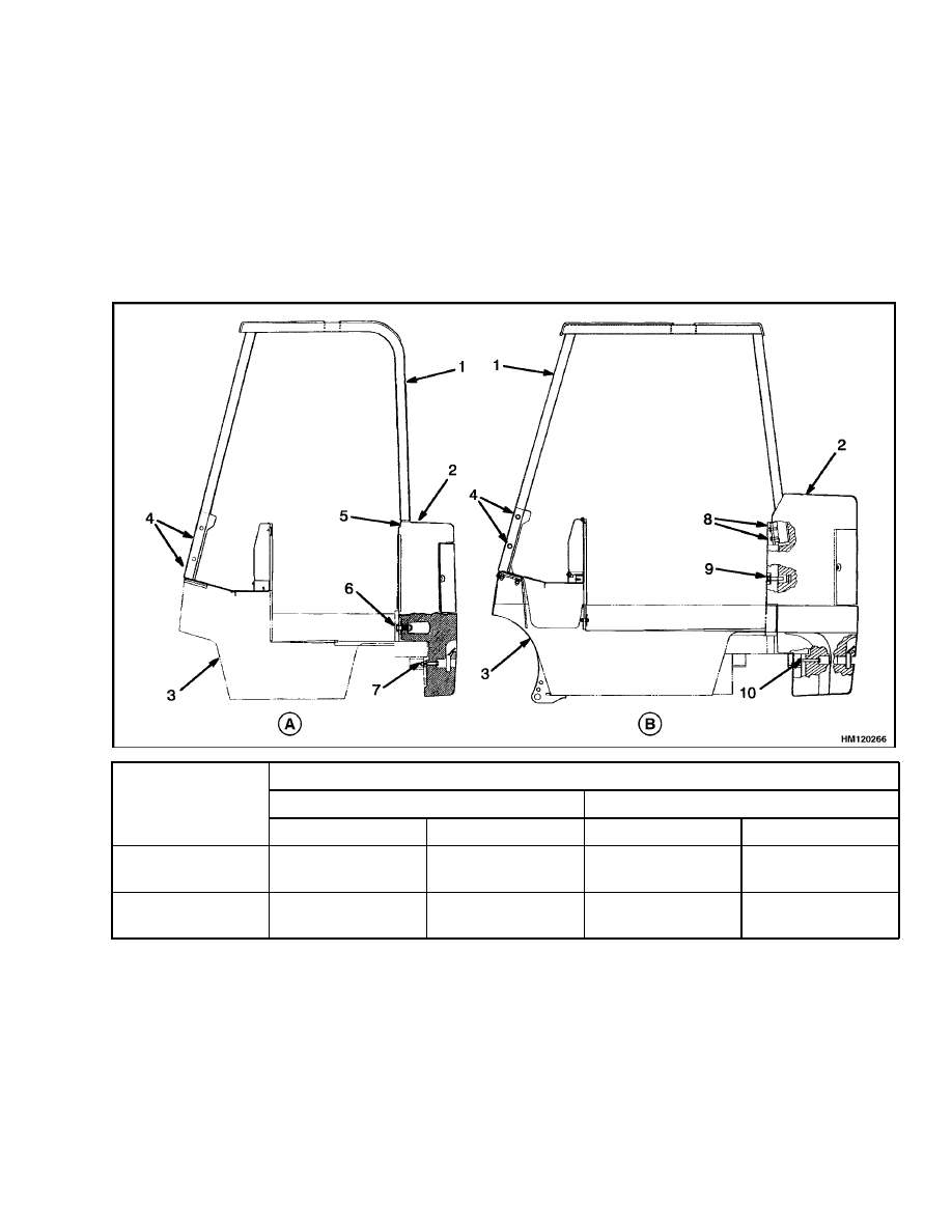
INSTALL
Put overhead guard on lift truck. Install any electric
wires from overhead guard supports through holes
in cowl. Install four capscrews, washers, and nuts
that hold front supports to cowl. Tighten capscrews
to correct torque. Install capscrews and washers that
hold rear supports to counterweight. Tighten cap-
screws to correct torque. The correct torque values
are shown in Figure 3. Install battery.
Torque Values
Overhead Guard
Counterweight
Model
Front
Rear
Upper
Lower
E1.25-3.00XL
(E/J25-60XL)
86 N•m (64 lbf ft)
435 N•m (320 lbf ft)
435 N•m (320 lbf ft)
66 N•m (49 lbf ft)
E3.50-5.50XL
(E70-120XL)
86 N•m (64 lbf ft)
86 N•m (64 lbf ft)
270 N•m (200 lbf ft)
66 N•m (49 lbf ft)
A. E/J1.25-3.00XL (E/J25-60XL)
B. E3.50-5.50XL (E70-120XL)
1.
OVERHEAD GUARD (OHG)
2.
COUNTERWEIGHT (CWT)
3.
FRAME
4.
CAPSCREWS (4) OHG-FRONT
5.
CAPSCREWS (2) OHG-REAR
6.
CAPSCREWS (2) CWT-UPPER
7.
CAPSCREWS (2) CWT-LOWER
8.
CAPSCREWS (2) OHG-UPPER
9.
CAPSCREWS (2) CWT-UPPER
10. CAPSCREWS (2) CWT-LOWER
Figure 3. Frame, Overhead Guard, and Counterweight
9
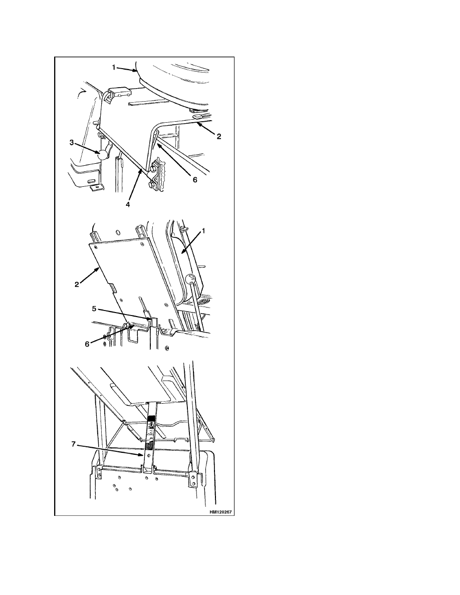
Battery Restraint and Seat Assembly Repair
100 SRM 284
Battery Restraint and Seat Assembly Repair
A battery restraint system is installed as a safety de-
vice. The function of the battery restraint system,
when correctly locked in the down position, is to hold
the battery in the battery compartment if an accident
causes the lift truck to tip over. The battery restraint
is a steel plate that is connected to the frame with a
hinge. A sliding latch mechanism locks the battery
restraint in the down position for operation. A knob
near the hinge unlocks the battery restraint from the
frame so the battery restraint can be raised to the
up position for access to the battery. The battery
restraint is also the support for the seat. A spring
brace holds the seat and battery restraint in the up
position. The operator must hold the seat assembly
with one hand. Use the other hand on the knob to re-
lease the spring brace and lower the seat and battery
restraint assembly to the operating position. Make
sure that the battery restraint is correctly locked to
the frame for operation of the lift truck.
An additional battery retention bar is used on models
E3.50-5.50XL (E70-120XL, E70-120XL
3
) where bat-
teries can be longer. This bar has a hinge fastened to
the counterweight and is part of the hood mechanism
on lift truck with hoods. The bar is also installed on
lift trucks without hoods.
Spacers are used inside the battery compartment to
prevent horizontal movement of the battery.
WARNING
The battery restraint and its latch mechanisms
must operate correctly before a lift truck is op-
erated. Make sure the battery has a cover if the
lift truck does not have a hood.
To operate correctly, the battery restraint plate must
be locked in the down position. On E3.50-5.50XL
(E70-120XL, E70-120XL
3
) units, the battery reten-
tion bar (and hood) must be lowered first; then the
battery restraint plate is locked in the down posi-
tion over the bar. The battery must have spacers to
prevent movement in any one horizontal direction of
13 mm (0.5 in.) maximum. See Figure 4. Use the
knob near the hinge to release the battery restraint
plate. Use the handle on the restraint plate to raise
the plate and seat. A spring brace will hold the as-
sembly in the up position. If installed, raise the hood.
Make sure that the battery cannot move more than
a total of 13 mm (0.5 in.) in any one horizontal di-
rection. Make sure the correct spacers are installed
to prevent the movement. See your Hyster lift truck
dealer to replace damaged or missing spacers. If a
smaller battery of the correct weight (see nameplate)
is installed and the spacers cannot prevent move-
ment, your Hyster lift truck dealer has larger spac-
ers. Push the seat and the battery restraint down
until the latch locks. Make sure battery restraint
is locked securely. Lift on battery restraint to make
sure it is latched and will not move.
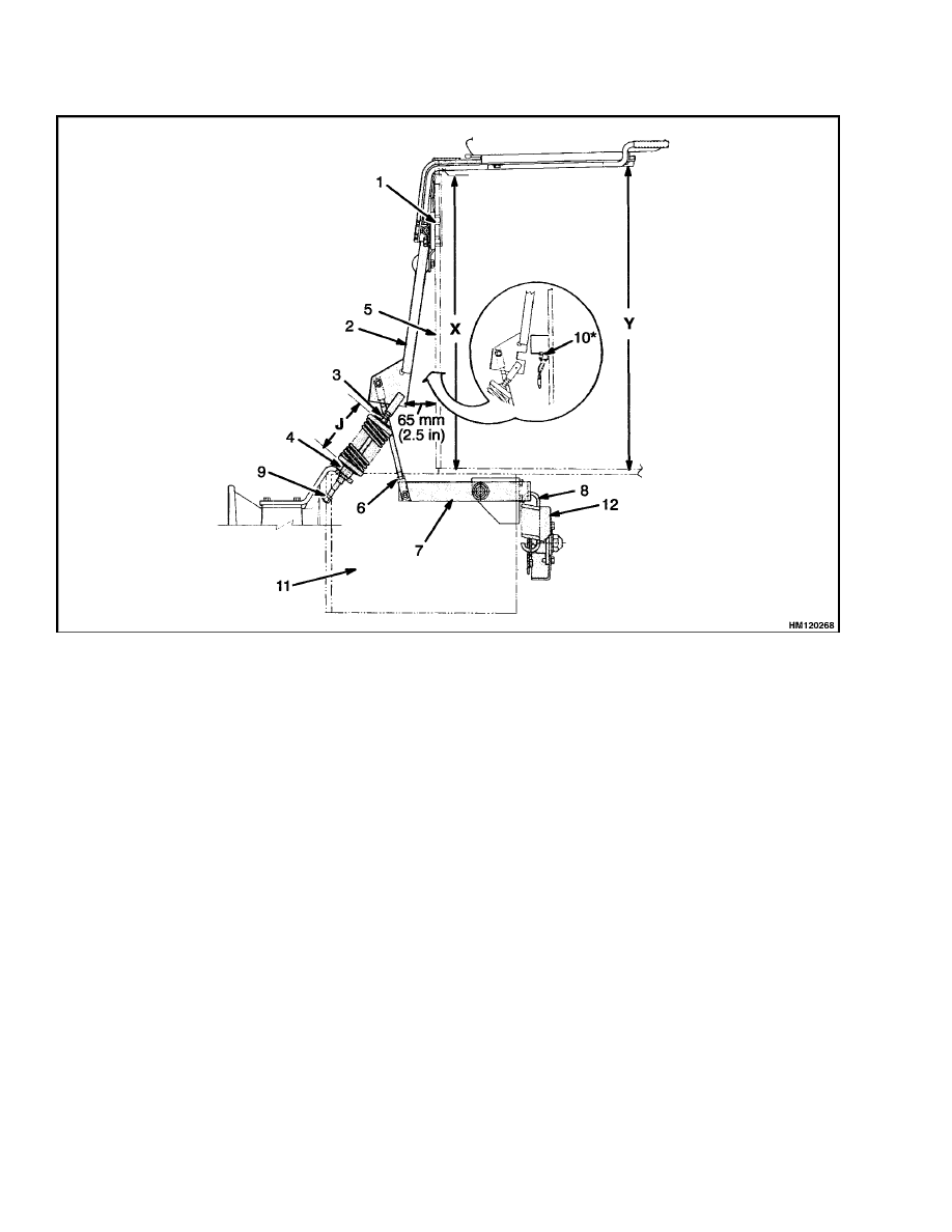
SEAT BRAKE ASSEMBLY E/J1.25-3.00XL
(E/J25-60XL), ADJUST
1.
Put a weight in the seat to release the seat
brake.
Measure dimensions X and Y. Add or
remove shims under the clamp so dimension
Y is 6 to 9 mm (0.23 to 0.35 in.) greater than
dimension X. See Figure 5.
2.
Adjust setscrew at top of lever so bottom of lever
is 65 mm (2.5 in.) from front plate of battery
compartment.
3.
Turn spring adjustment so length is dimension J.
Dimension J:
Standard Seat
63 mm (2.46 in.)
E/J1.25-1.75XL
(E25-35XL)
Suspension Seat
74 mm (2.91 in.)
Standard Seat
107 mm (4.13 in.)
E/J2.00-3.00XL
(E/J40-60XL)
Suspension Seat
118 mm (4.65 in.)
4.
Adjust length of rod to remove clearance in lever
and spring. Make sure adjustment does not ap-
ply brake.
10
100 SRM 284
Battery Restraint and Seat Assembly Repair
Figure 4. Battery Restraint and Seat Assembly
Legend for Figure 4
1.
SEAT
2.
BATTERY RESTRAINT PLATE
3.
KNOB FOR LATCH MECHANISM
4.
HINGE
5.
LATCH
6.
SPRING BRACE
7.
BATTERY RETENTION BAR E3.50-5.50XL
(E70-120XL, E70-120XL
3
) ONLY
5.
Raise seat to up position and make sure the
jam nuts do not hit bearing.
Test operation
of seat brake to make sure seat brake is actu-
ated correctly.
Make sure measurements for
linkage adjustments are correctly done. If seat
brake does not correctly actuate brake after
adjustments have been made, make additional
adjustments to length of rod.
6.
The seat can be removed from the battery re-
straint plate by removing four bolts. The battery
restraint plate is removed from the frame by re-
moving the hinge pin that holds the assembly to
the frame.
11
Battery Restraint and Seat Assembly Repair
100 SRM 284
1.
CLAMP
2.
LEVER
3.
SPRING ADJUSTMENT
4.
BEARING
5.
FRONT PLATE BATTERY
COMPARTMENT
6.
ROD ADJUSTMENT
7.
LEVER
8.
SPRING
9.
JAM NUTS
10. BRAKE SWITCH
11. MOTOR
12. BRAKE ASSEMBLY
*THE LATEST LIFT TRUCKS EQUIPPED WITH A SEAT BRAKE NO LONGER HAVE A SWITCH LOCATED IN THE
SEAT. THE BRAKE SWITCH IS ATTACHED TO THE FRONT PLATE OF THE BATTERY COMPARTMENT. ALSO,
THE POWER STEERING TIMER HAS BEEN REPLACED WITH A FILTER.
LIFT TRUCKS THAT ARE NOT EQUIPPED WITH A SEAT BRAKE WILL STILL HAVE A SWITCH LOCATED IN
THE SEAT TO ACTIVATE THE POWER STEERING CIRCUIT. THESE UNITS WILL CONTINUE TO USE A POWER
STEERING TIMER.
Figure 5. Seat Brake Assembly E/J1.25-3.00XL (E/J25-60XL)
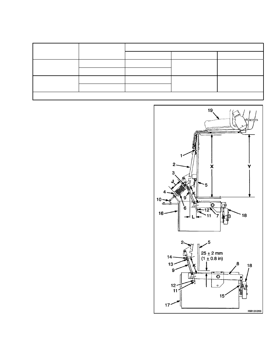
SEAT BRAKE ASSEMBLY E3.50-5.50XL
(E70-120XL), ADJUST
1.
Put a weight in the seat to release seat brake.
Measure dimension X and Y. Add or remove
shims under clamp so dimension Y is equal to
dimension X within ±3 mm (0.12 in.). Use equal
number shims under each clamp. See Figure 6.
2.
Adjust setscrew at top of lever so bottom of lever
equals dimension L from front plate of battery
compartment.
NOTE:
This adjustment can be made with the spring
assembly removed from the lift truck.
3.
Adjust spring adjustment so length is dimension
J.
4.
On 280 mm (11 in.) diameter motor: Adjust
lever to a level position using nut. On 330 mm
(13 in.) diameter motor: Adjust lever to 25
±2 mm (1 ±0.08 in.) using nut. Lock nut with jam
nut. Make sure this adjustment does not apply
the brake. See Table 5.
12
100 SRM 284
Battery Restraint and Seat Assembly Repair
Table 5. Seat Brake Adjustment
Dimension
Motor Dia.
Seat Type
J
K
L
Standard
80 mm (3.2 in.)*
280 mm (11 in.)
Suspension
75 mm (2.9 in.)
173 mm (6.7 in.)
65 mm (2.5 in.)
Standard
85 mm (3.3 in.)**
330 mm (13 in.)
Suspension
80 mm (3.2 in.)
165 mm (6.5 in.)
55 mm (2.1 in.)
* 90 mm (3.5 in.), ** 80 mm (3.2 in.) on early models.
5.
Adjust spring to dimension K. Lock nut with jam
nut. This adjustment can be made with spring
assembly removed from lift truck.
6.
Adjust position of rod end so brake will start to
apply when brake lever is raised 3 mm (0.12 in.)
or less. Rotate brake drum by hand to feel brake
start to apply.
7.
Test operation of seat brake to make sure seat
brake is actuated correctly. Make sure linkage
is adjusted to correct measurements.
If seat
brake does not correctly actuate brake after ad-
justments have been made, adjust length of rod
again and make sure dimension is correct.
8.
The seat can be removed from the battery re-
straint plate. Remove four bolts. The battery
restraint plate can be removed from the frame.
Remove hinge pin that holds assembly to frame.
Figure 6. Seat Brake Assembly E3.50-5.50XL
(E70-120XL, E70-120XL
3
)
13

Counterweight Repair
100 SRM 284
Legend for Figure 6
1.
CLAMP
2.
LEVER
3.
SPRING ADJUSTMENT
4.
BEARING
5.
FRONT PLATE BATTERY COMPARTMENT
6.
SPRING ASSEMBLY
7.
MOTOR LEVER
8.
MOTOR LEVER
9.
SPRING
10. JAM NUT
11. JAM NUT
12. ADJUSTMENT NUT
13. ADJUSTMENT NUT
14. JAM NUT
15. SETSCREW
16. MOTOR 280 mm (11 in.)
17. MOTOR 330 mm (13 in.)
18. BRAKE
19. SEAT
Counterweight Repair
If the lift truck must be put on blocks for mainte-
nance and repair, see Periodic Maintenance 8000
SRM 291 section How to Put a Lift Truck on
Blocks.
WARNING
The counterweight is very heavy. Make sure
that the crane and lifting devices have enough
lifting capacity to safely lift the counterweight.
The weights of the counterweights are shown
in Table 6.
The counterweight normally is not removed for most
repairs.
Replacement of some large parts of the
SCR electronic controller is easier when the counter-
weight is removed. The counterweight is fastened to
the frame with four capscrews. The weights for the
counterweights are in Table 6.
Table 6. Counterweights
Model (mm)*
Weight
E/J1.25XL (E25XL)
300 kg (661 lb)
E/J1.50XL (E30XL)
506 kg (1116 lb)
E/J1.75XL (E35XL)
678 kg (1495 lb)
E2.00XL (E40XL) 695 mm
562 kg (1239 lb)
E2.00XL (E40XL) 842 mm
373 kg (822 lb)
E2.50XL (E50XL) 694 mm
975 kg (2150 lb)
E2.50XL (E50XL) 842 mm
660 kg (1455 lb)
E3.00XL (E60XL) 842 mm
975 kg (2150 lb)
E3.50XL (E70XL) 1018 mm
700 kg (1545 lb)
E4.00XL (E80XL) 1018 mm
1134 kg (2500 lb)
E4.50XL (E100XL) 1183 mm
1134 kg (2500 lb)
*mm dimensions are battery compartment sizes.
Table 6. Counterweights (Continued)
Model (mm)*
Weight
E4.50XLS (E100XLS) 1018
mm
1747 kg (3850 lb)
E5.50XL (E120XL) 1183 mm
1747 kg (3850 lb)
J2.00XL (J40XL) All
373 kg (822 lb)
J2.50XL (J50XL) 842 mm
373 kg (822 lb)
J2.50XL (J50XL) 1010 mm
373 kg (822 lb)
J3.00XL (J60XL) 1010 mm
373 kg (822 lb)
*mm dimensions are battery compartment sizes.
REMOVE
1.
Remove battery.
See the Periodic Mainte-
nance 8000 SRM 291 section of this manual
under How to Change the Battery.
2.
Remove overhead guard as described in the para-
graphs under Overhead Guard Repair, Remove.
3.
Install lifting eyebolts in holes that are used
to fasten overhead guard to counterweight
on E/J1.25-3.00XL (E/J25-60XL) models.
The
E3.50-5.50XL (E70-120XL, E70-120XL
3
) models
have a hole on top of the counterweight for a
single eye bolt. Attach chain or sling to eyebolts.
Use crane to hold the weight of the counter-
weight. See Figure 3 and Figure 7.
4.
From inside the battery compartment, remove
two capscrews that hold counterweight to frame.
Remove two capscrews from tow pin area of coun-
terweight. Use crane to lift counterweight away
from frame. Make sure you do not damage the
electronic controls.
14
100 SRM 284
Traction Motor Repair
NOTE: E5.50XL (E120XL, E70-120XL, E70-120XL
3
)
MODEL SHOWN.
1.
LIFTING EYEBOLT
2.
CAPSCREWS
3.
TOW PIN
Figure 7. Lift Counterweight
INSTALL
NOTE:
The access panel to the electronic controller
can be removed from the counterweight to make
checks and adjustments on the controller.
Make
sure lugs are correctly engaged when access panel is
installed again or panel will fall from counterweight
during operation.
1.
Use crane to lift counterweight into position.
Make sure you do not damage electronic con-
troller. Install two upper capscrews from inside
battery compartment that hold counterweight
to frame.
Install two lower capscrews in tow
pin area of counterweight. Tighten capscrews
to correct torque. The correct torque values for
capscrews are shown in Figure 3.
2.
Disconnect sling or chain. Remove eyebolts from
counterweight.
3.
Install overhead guard as described in the para-
graphs for the Overhead Guard Repair, Install.
4.
Install battery.
See Periodic Maintenance
8000 SRM 291 section How to Change the
Battery.
Traction Motor Repair
REMOVE
This procedure will show the removal of the traction
motor through the battery compartment. Some lift
trucks have a seat brake that actuates the brake on
the armature shaft of the traction motor. See Fig-
ure 8. The seat brake linkage must be disconnected
at the front of the traction motor before the motor is
removed.
NOTE:
The traction motor can also be removed from
under the lift truck with the use of a floor jack, but is
more difficult. The lift truck must be on blocks with
clearance for the jack and traction motor if the trac-
tion motor is removed from under the lift truck. The
hydraulic lines from the hydraulic tank must also be
disconnected if the traction motor is removed from
under the lift truck.
1.
Remove battery. Remove floor plates and access
panel in bottom of battery compartment.
2.
Disconnect seat brake linkage. Disconnect hy-
draulic line to main control valve so motor mount
can be disconnected. Put caps on open hydraulic
fittings.
Disconnect power cables from traction motor.
Make an identification of which cable is con-
nected to each terminal.
4.
Put lift truck on blocks for easier access to bottom
bolts between traction motor and speed reducer.
Remove bolts between speed reducer and motor.
5.
Install sling to hold traction motor. See Figure 9.
Use wood block and board under sling as shown
in the illustration to control traction motor dur-
ing removal and installation. Use crane to hold
weight of traction motor. See Figure 10.
15
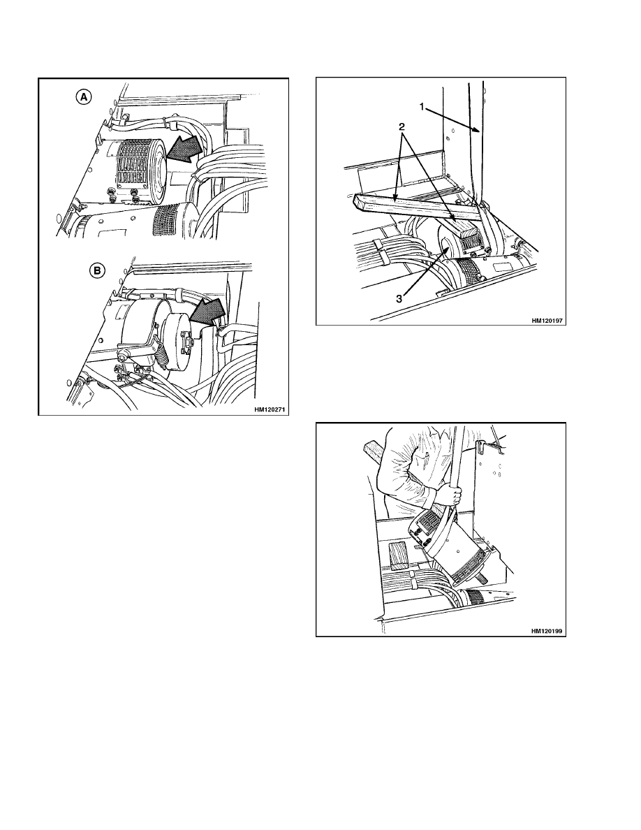
Traction Motor Repair
100 SRM 284
A. TRACTION MOTOR
B. TRACTION MOTOR WITH OPTIONAL SEAT
BRAKE
Figure 8. Traction Motor
NOTE:
The traction motors are in different configura-
tions for different applications of the lift trucks. Trac-
tion motors weigh approximately 90 to 140 kg (200 to
310 lb). Make sure the sling cannot slide and permit
traction motor to fall.
6.
Remove motor mount that holds traction motor
to frame. Pull traction motor from speed reducer.
7.
Use crane to move traction motor to a space to
make repairs.
1.
SLING
2.
USE WOOD BLOCK AND BOARD UNDER SLING
FOR A LEVER
3.
TRACTION MOTOR
Figure 9. Sling Installation to Lift Traction
Motor
Figure 10. Use Crane to Lift Traction Motor
16
100 SRM 284
Hydraulic Tank Repair
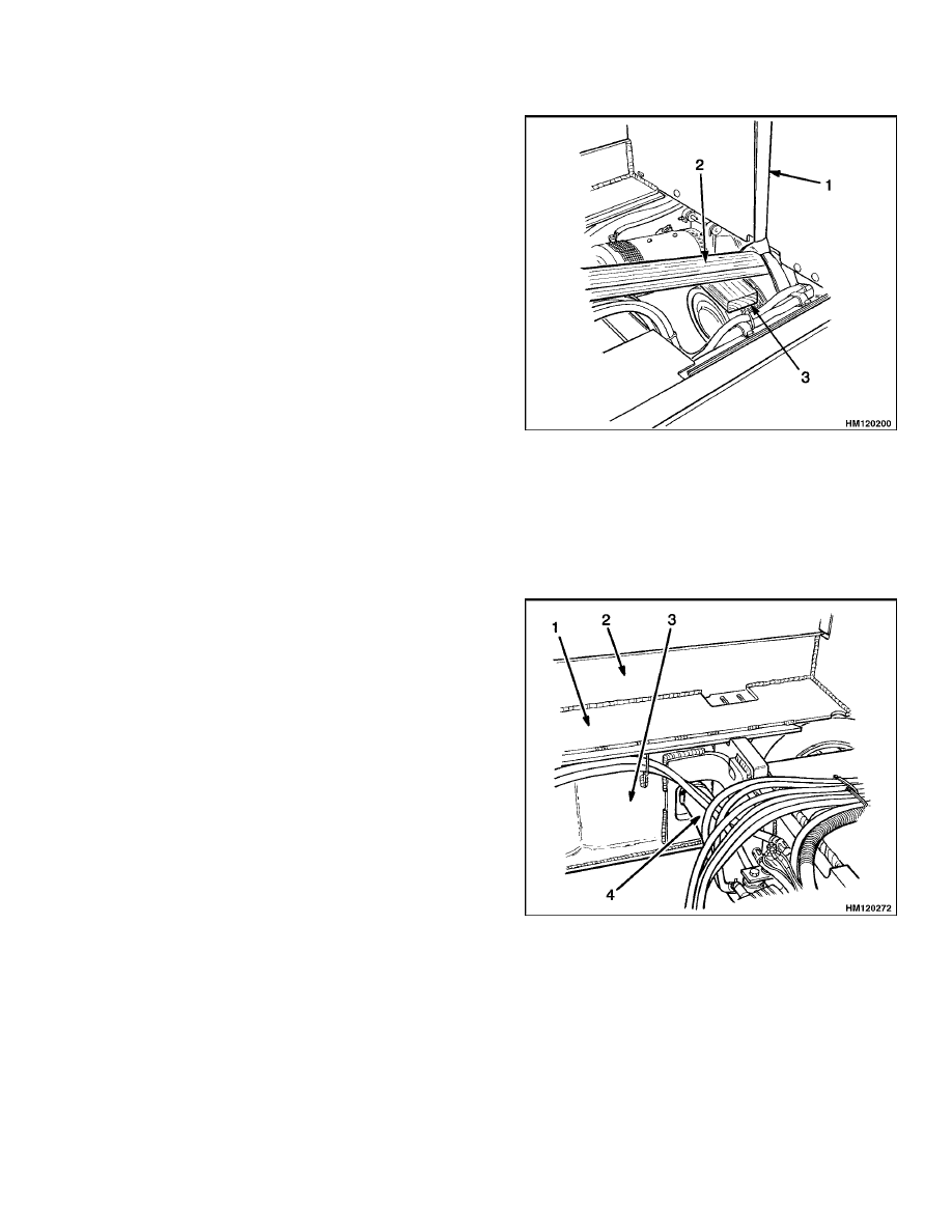
INSTALL
1.
Install sling to lift traction motor. Use wood block
and board under sling as shown in Figure 9 to
control traction motor during installation.
2.
Lower traction motor into position in lift truck.
Align traction motor with speed reducer. See Fig-
ure 11.
3.
Use board or prybar as necessary to push traction
motor into speed reducer.
4.
Align bolt holes in speed reducer and motor
housing.
Install bolts that hold traction mo-
tor to speed reducer. Tighten bolts to 38 N•m
(28 lbf ft).
5.
Remove sling and install traction motor mount.
6.
Connect inlet hydraulic line to main control
valve. Install power cables.
1.
SLING
2.
BOARD
3.
WOOD BLOCK
Figure 11. Align Traction Motor with Speed
Reducer
Hydraulic Tank Repair
INSPECT
Make a visual inspection of all sides of the tank. In-
spect welds for cracks and leakage. Check for wet ar-
eas, accumulation of dirt, and loose or missing paint
caused by leakage. Areas of the tank that are not eas-
ily seen can be checked with an inspection mirror and
a light that is approved for locations with flammable
vapors.
E/J1.25-3.00XL (E/J25-60XL) The hydraulic tank
is plastic and is normally replaced if it is damaged.
The traction motor must be removed before the hy-
draulic tank can be replaced. A bracket on the front
plate of the battery compartment holds the hydraulic
tank in position. The hydraulic tank must be drained
through one of the hydraulic supply hoses. Discon-
nect hydraulic hoses from hydraulic tank when it
must be replaced.
E3.50-5.50XL
(E70-120XL,
E70-120XL
3
)
The
hydraulic tank is part of the frame weldment and
cannot be removed from the lift truck. See Figure 12.
Repairs for leaks in the hydraulic tank can require
special procedures described in the next paragraphs.
1.
HYDRAULIC TANK
2.
OUTER FRAME
3.
INNER FRAME
4.
SUCTION PIPE
Figure 12. Hydraulic Tank E3.50-5.50XL
(E70-120XL, E70-120XL
3
) Models
17

Hydraulic Tank Repair
100 SRM 284
SMALL LEAKS, REPAIR
Use the following procedure to seal small leaks:
1.
Use steam to clean area around leak. Remove all
paint and dirt around leak.
WARNING
Do not use tools that can make sparks, heat, or
static electricity. The vapors in the tank can
cause an explosion.
2.
Apply Loctite
®
290 to leak. Follow instructions
of manufacturer.
LARGE LEAKS, REPAIR
1.
Use one of the procedures described under Clean
in this section to clean and prepare the tank for
repairs.
2.
Use acceptable welding practices to repair tank.
See the American National Standard Safety In
Welding and Cutting ANSI Z 49.1 - 1973.
CLEAN
WARNING
Special procedures must be followed when
large leaks or other repairs need welding or
cutting. All work must be done by authorized
personnel. If the tank is cleaned inside of a
building, make sure there is enough ventila-
tion. See the following manuals for additional
information:
• Safe Practices for Welding and Cutting Con-
tainers That Have Held Combustibles by the
American Welding Society, A6.0-65
• Safety In Welding and Cutting, American Na-
tional Standard, ANSI Z 49.1 - 1973
When cleaning tank, do not use solutions that make
dangerous gases at normal temperatures or when
heated. Wear eye and face protection. Protect the
body from burns.
When cleaning with steam, use a hose with a mini-
mum diameter of 19 mm (0.75 in.). Control the pres-
sure of the steam by a valve installed at the nozzle of
the hose. If a metal nozzle is used, it must be made of
a material that does not make sparks. Make an elec-
trical connection between nozzle and tank. Connect
ground wire to tank to prevent static electricity.
Steam Method
Use the following procedure to clean the tank with
steam:
1.
Remove all parts from tank. Install drain plug.
2.
Fill tank 1/4 full with a solution of water and
sodium bicarbonate or sodium carbonate. Mix
0.5 kg (1 lb) per 4 liter (1 gal) of water.
3.
Mix solution in tank using air pressure. Make
sure all surfaces on inside of tank are flushed
with solution. Drain tank.
4.
Put steam into tank until tank does not have
odors and metal is hot. Steam vapors must come
from all openings.
5.
Flush inside of tank with boiling water. Make
sure all loose material is removed from inside of
tank.
6.
Make inspection of inside of tank. If it is not
clean, repeat Step 4 and Step 5 and make another
inspection. When making inspections, use a light
that is approved for locations with flammable va-
pors.
7.
Put plugs in all openings in tank. Wait 15 min-
utes, then remove inlet and outlet plugs. Test a
sample of the vapor with a special indicator for
gas vapors. If the amount of flammable vapors
is above the lower flammable limit, repeat the
cleaning procedures.
Chemical Solution Method
If the tank cannot be cleaned with steam, use the
following procedure:
1.
Mix a solution of water and trisodium phosphate
or a cleaning compound with an alkali base. Fol-
low the instructions given by the manufacturer.
WARNING
Compressed air can move particles so that they
cause injury to the user or to other personnel.
Make sure that the path of the compressed air
is away from all personnel.
Wear protective
goggles or a face shield to prevent injury to the
eyes.
2.
Fill tank with cleaning solution. Use compressed
air to mix solution in tank.
18
100 SRM 284
Painting Instructions
3.
Drain tank. Flush inside of tank with hot (boil-
ing) water. Make sure all cleaning compound is
removed.
4.
Make an inspection of inside of tank. If tank is
not clean, repeat Step 1 through Step 3. Make
another inspection of tank. When making inspec-
tions, use a light that is approved for locations
with flammable vapors.
5.
Check tank for flammable vapors using a spe-
cial indicator for gas vapors. If the amount of
flammable vapors is above the lower flammable
limit, repeat the cleaning procedures.
ADDITIONAL PREPARATIONS FOR
REPAIR
If nitrogen gas or carbon dioxide gas is available, pre-
pare the tank for welding using these gases. See the
manual Safe Practices For Welding and Cutting Con-
tainers That Have Held Combustibles by the Ameri-
can Welding Society, A6.0-65. If these gases are not
available, another method using water can be used
as follows:
1.
Fill tank with water to just below the point where
the work will be done. Make sure the space above
the level of the water has a vent.
2.
Use acceptable welding practices to repair tank.
See the American National Standard "Safety in
Welding and Cutting," ANSI Z 49.1 - 1973.
Painting Instructions
WARNING
Always use solvents and paints in an area
with ventilation. Do not use solvents or paints
near heat, fire, or electrical equipment that
can make sparks. Follow the manufacturer’s
instructions and Cautions.
1.
Remove all dirt from surface to be painted. Clean
area to be painted. Use a solvent for painted sur-
faces to remove grease and oil before sanding. Do
not use solvent on new paint. Make sure all oil
and grease is removed.
2.
Use sandpaper to remove top surface of paint and
rust from metal. All metal surfaces where paint
is completely removed must be painted. Use a
primer. Apply primer before applying final coat
of paint.
3.
Protect all surfaces that will not be painted. See
the list of items in Figure 13.
CAUTION
Do not paint the pads, plastic covers or knobs,
cables, labels, and information plates or con-
trols. Paint can make some assemblies not op-
erate correctly.
4.
Paint surfaces.
Use correct paint from your
dealer for Hyster lift trucks. Follow directions
on container. The correct arrangement of colors
is shown in the note in Figure 13.
WARNING
Make sure all labels are installed after paint-
ing is complete. Safety labels are installed on
the lift truck to give information about possi-
ble hazards. It is important that all safety la-
bels are installed on the lift truck and can be
read.
5.
Check that all safety labels are installed in cor-
rect locations on lift truck. New labels are avail-
able from your dealer for Hyster lift trucks.
19
Painting Instructions
100 SRM 284
NOTE: USE COLORS APPROVED BY HYSTER. DO NOT PAINT THE FOLLOWING ITEMS: PEDAL PADS, LEVER
KNOBS, INSTRUMENTS, STEERING WHEEL, SEAT ASSEMBLY AND SEAT RAILS, INFORMATION CASE AND
COVER, TIRES, MAST CHAINS AND HOSES, ALL LABELS AND INFORMATION PLATES, BATTERY CONNEC-
TOR, PARKING BRAKE HANDLE, KEY SWITCH, CYLINDER RODS, ALL PLASTIC COVERS, AND STEERING
COLUMN COVER.
NOTE: LIGHT AREAS = YELLOW, DARK AREAS = BLACK, AND FORKS = RED.
Figure 13. Color Arrangement
20

100 SRM 284
Safety Label Replacement
Safety Label Replacement
If the labels or information plates are missing or have
damage, they must be replaced. See Figure 14, Fig-
ure 15, Figure 16, and Figure 17.
WARNING
Labels that have WARNINGS or CAUTIONS
must be replaced if they are damaged. If an
upright of a different size or an accessory
carriage is installed, the capacity rating can
change.
Changes in the kind of drive tires
can change the capacity rating.
See a HYS-
TER Dealer for a replacement nameplate. The
nameplate information is a safety item and
must be correct for the equipment and config-
uration of the lift truck.
NOTE:
The nameplate is installed using rivets. The
old rivets must be removed before installing a new
nameplate.
1.
Make sure surface is dry and has no oil or grease.
Do not use solvent on new paint. Clean surface
of old paint using a cleaning solvent.
2.
Remove paper from back of label. Do not touch
adhesive surface.
3.
Carefully hold label in correct position above sur-
face. The label cannot be moved after it touches
the surface. Put label on surface. Make sure all
air is removed from under label and corners and
edges are tight.
21
Safety Label Replacement
100 SRM 284
NOTE: INSTALL NEW LABEL IN SAME LOCATION AS ORIGINAL.
1.
MODEL LABEL
2.
MAST WARNING LABEL
3.
PARKBRAKE WARNING LABEL
4.
HYSTER LABEL
5.
FORWARD/REVERSE LABEL
6.
OPERATOR WARNING LABEL
7.
LIFTING EYE LABEL
8.
BATTERY DISCONNECT LABEL
9.
LIFT/TILT LABEL
10. PINCH POINT LABEL
11. AUXILIARY FUNCTION LABEL
12. XLX LABEL
13. CORROSION LABEL
14. TIPOVER WARNING LABEL
15. BATTERY SPACER LABEL
16. NO RIDERS LABEL
17. SLIP RESISTANT TREAD
18. MAST WARNING LABEL
19. HYSTER LABEL
20. EE/ES LABEL
21. OPERATOR RESTRAINT LABEL
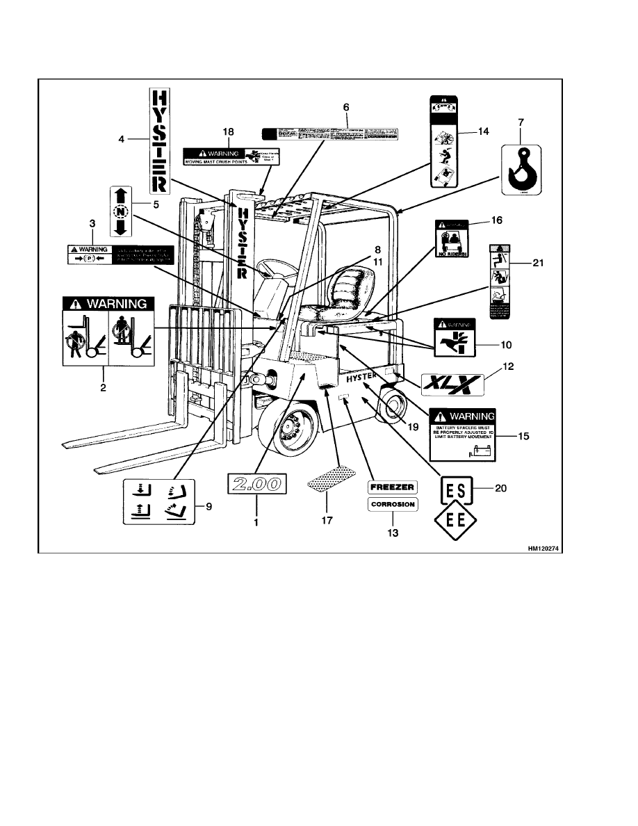
Figure 14. Label Positions E/J2.00-3.00XL (E40-60XL) Models
22
100 SRM 284
Safety Label Replacement
NOTE: INSTALL NEW LABEL IN SAME LOCATION AS ORIGINAL.
1.
OPERATOR WARNING LABEL
2.
TIPOVER WARNING/OPERATOR RESTRAINT
LABEL
3.
NO RIDERS LABEL
4.
LIFT/TILT LABEL
5.
IMPACT RATING (US) PLATE
6.
BATTERY SPACER LABEL
7.
PARKBRAKE WARNING LABEL
8.
MAST WARNING LABEL
9.
MAST WARNING LABEL
10. HYSTER LABEL
11. FORWARD/REVERSE LABEL
12. AUXILIARY FUNCTIONS LABEL
13. MODEL LABEL
14. BATTERY DISCONNECT LABEL
15. XL2 LABEL
16. HYSTER LABEL
17. PINCH POINT LABEL
18. CORROSION LABEL
19. FREEZER LABEL
20. EE LABEL
21. ES LABEL
22. LIFTING EYE LABEL
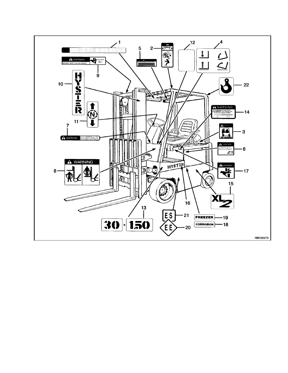
Figure 15. Label Positions E/J1.25-1.75XL (E25-35XL) Models
23
Safety Label Replacement
100 SRM 284
NOTE: INSTALL NEW LABEL IN SAME LOCATION AS ORIGINAL.
1.
MODEL LABEL
2.
MAST WARNING LABEL
3.
HYSTER LABEL
4.
OPERATORS WARNING LABEL
5.
CORROSION/FREEZER LABEL
6.
NO RIDERS LABEL
7.
BATTERY DISCONNECT LABEL
8.
EE/ES LABEL
9.
PARKBRAKE WARNING LABEL
10. PINCH POINT LABEL
11. LIFT/TILT LABEL
12. AUXILIARY LABEL
13. FORWARD/REVERSE LABEL
14. TIPOVER WARNING LABEL
15. BATTERY SPACER LABEL
16. OPERATOR RESTRAINT LABEL
17. MAST WARNING LABEL
18. XL2 LABEL
19. XLX LABEL
20. HYSTER LABEL
21. GUARD LABEL
22. SLIP RESISTANT TREAD
Figure 16. Label Positions E3.50-5.50XL (E70-120XL) Models
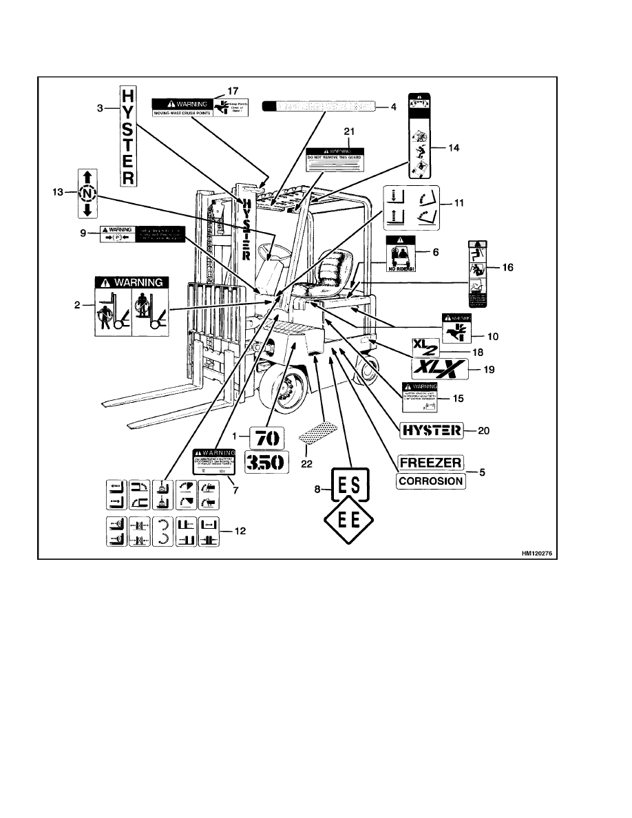
24
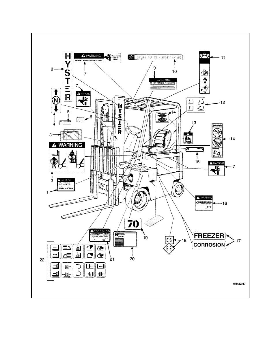
100 SRM 284
Safety Label Replacement
Figure 17. Label Positions, E3.50-5.50XL (E70-120XL
3
)
25

Safety Label Replacement
100 SRM 284
Legend for Figure 17
1.
PARKING BRAKE WARNING LABEL
2.
MAST WARNING LABEL
3.
CAPACITY PLATE
4.
FORWARD/REVERSE LABEL
5.
NOTICE TO USER LABEL
6.
UL LABEL
7.
PINCH POINT LABEL
8.
HYSTER LABEL
9.
OVERHEAD GUARD LABEL
10. OPERATOR WARNING LABEL
11. OPERATOR RESTRAINT LABEL
12. LIFT/TILT LABEL
13. NO RIDERS LABEL
14. BATTERY RESTRAINT LABEL
15. UL INSPECTION PLATE
16. BATTERY SPACER LABEL
17. OPTION LABEL
18. EE/ES LABEL
19. MODEL LABEL
20. PATENT LABEL
21. BATTERY DISCONNECT LABEL
22. AUXILIARY CONTROLS
26

TECHNICAL PUBLICATIONS
100 SRM 284
10/02 (7/00)(2/97)(6/90)(7/88)(10/85)(4/85) Printed in United Kingdom
Document Outline
- toc
- tables
Wyszukiwarka
Podobne podstrony:
897656 1300SRM0568 (10 1999) UK EN
897480 1400SRM0499 (10 2004) UK EN
1596602 0100SRM1200 (07 2005) UK EN
1452930 8000SRM0680 (12 2002) UK EN
1494145 8000SRM0940 (10 2003) UK EN
1526432 8000SRM1041 (07 2002) UK EN
1482603 0100SRM0793 (03 2000) UK EN
1466241 1600SRM0732 (10 2003) UK EN
1559550 2200SRM1097 (10 2004) UK EN
1453608 1600SRM0687 (03 2002) UK EN
899784 2200SRM0002 (10 2003) UK EN
1519772 2200SRM1016 (10 2004) UK EN
1456997 8000SRM0708 (10 2004) UK EN
897658 1800SRM0570 (10 1999) UK EN
1566270 0100SRM1118 (08 2004) UK EN
897983 1600SRM0655 (03 2002) UK EN
897121 1900SRM0339 (10 2003) UK EN
897395 8000SRM0454 (10 2003) UK EN
więcej podobnych podstron