FRAME
A1.00-1.50XL (A20-30XL) [C203]
PART NO. 1482603
100 SRM 793

SAFETY PRECAUTIONS
MAINTENANCE AND REPAIR
• When lifting parts or assemblies, make sure all slings, chains, or cables are correctly
fastened, and that the load being lifted is balanced. Make sure the crane, cables, and
chains have the capacity to support the weight of the load.
• Do not lift heavy parts by hand, use a lifting mechanism.
• Wear safety glasses.
• DISCONNECT THE BATTERY CONNECTOR before doing any maintenance or repair
on electric lift trucks.
• Disconnect the battery ground cable on internal combustion lift trucks.
• Always use correct blocks to prevent the unit from rolling or falling. See HOW TO PUT
THE LIFT TRUCK ON BLOCKS in the Operating Manual or the Periodic Mainte-
nance section.
• Keep the unit clean and the working area clean and orderly.
• Use the correct tools for the job.
• Keep the tools clean and in good condition.
• Always use HYSTER APPROVED parts when making repairs. Replacement parts
must meet or exceed the specifications of the original equipment manufacturer.
• Make sure all nuts, bolts, snap rings, and other fastening devices are removed before
using force to remove parts.
• Always fasten a DO NOT OPERATE tag to the controls of the unit when making repairs,
or if the unit needs repairs.
• Be sure to follow the WARNING and CAUTION notes in the instructions.
• Gasoline, Liquid Petroleum Gas (LPG), Compressed Natural Gas (CNG), and Diesel fuel
are flammable. Be sure to follow the necessary safety precautions when handling these
fuels and when working on these fuel systems.
• Batteries generate flammable gas when they are being charged. Keep fire and sparks
away from the area. Make sure the area is well ventilated.
NOTE:
The following symbols and words indicate safety information in this
manual:
WARNING
Indicates a condition that can cause immediate death or injury!
CAUTION
Indicates a condition that can cause property damage!
Frame
Table of Contents
TABLE OF CONTENTS
General ...............................................................................................................................................................
Description .........................................................................................................................................................
Overhead Guard Repair ....................................................................................................................................
Remove ...........................................................................................................................................................
Install .............................................................................................................................................................
Hood and Seat Assembly Repair .......................................................................................................................
Remove ...........................................................................................................................................................
Install .............................................................................................................................................................
Counterweight Repair .......................................................................................................................................
Remove ...........................................................................................................................................................
Install .............................................................................................................................................................
Hydraulic Tank Repair ......................................................................................................................................
Inspect ............................................................................................................................................................
Small Leaks, Repair ......................................................................................................................................
Large Leaks, Repair ......................................................................................................................................
Clean ..............................................................................................................................................................
Steam Method............................................................................................................................................
Chemical Solution Method........................................................................................................................
Additional Preparations for Repair ..............................................................................................................
Safety Labels ......................................................................................................................................................
Battery Specifications........................................................................................................................................
This section is for the following models:
A1.00-1.50XL (A20-30XL) [C203]
©2002 HYSTER COMPANY
i

"THE
QUALITY
KEEPERS"
HYSTER
APPROVED
PARTS
100 SRM 793
Description
General
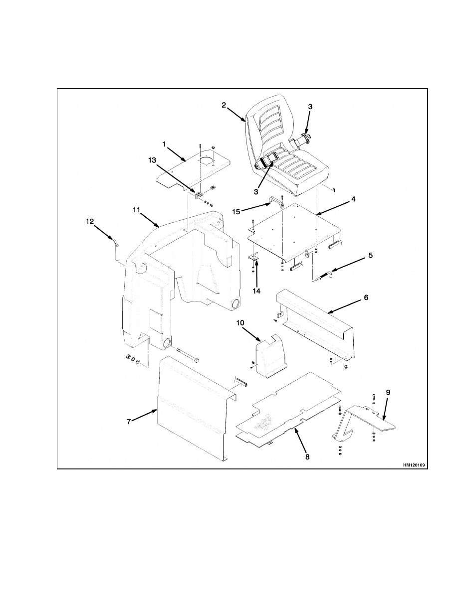
This section has a description and the service procedures for the parts of the frame. These parts include the
counterweight assembly, overhead guard, hydraulic tank, access panels, and positions for decals.
Description
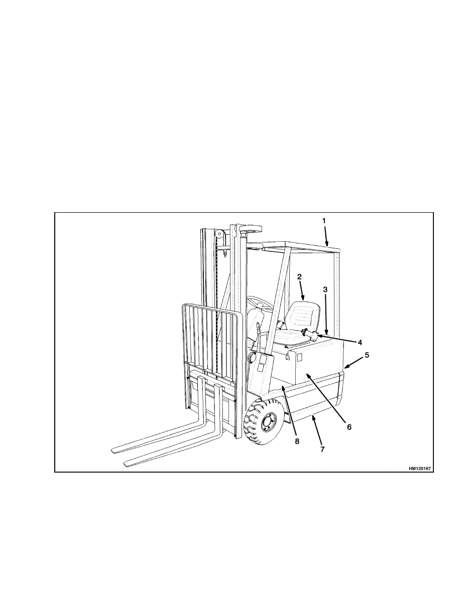
The frame is a single weldment with mounts for
the counterweight, overhead guard, mast and load
wheels, and the master drive unit. See Figure 1 and
Figure 3. The hydraulic tank is part of the frame.
The hood panel is composed of two parts, a front and
rear panel, that can be opened or removed for access
to the battery compartment, electronic controller,
and the traction motor on the master drive unit. Ac-
cess panels on each side of the lift truck are removed
by lifting them from the frame. These panels give
further access and protection to the battery.
The weight of the battery is the main part of the
counterweight system on an electric lift truck. Each
model of lift truck has a cast-iron counterweight with
a weight necessary for the indicated capacity. A slot
in the overhead guard permits removal of the battery
without removing the overhead guard.
1.
OVERHEAD GUARD
2.
SEAT ASSEMBLY
3.
HOOD
4.
OPERATOR RESTRAINT
5.
COUNTERWEIGHT
6.
LEFT SIDE PANEL (SHOWN)
7.
FRAME
8.
FLOOR PLATE
Figure 1. Frame Parts
1
Hood and Seat Assembly Repair
100 SRM 793
The hydraulic pump motor and the hydraulic tank
are under the floor plate in the operator compart-
ment. This floor plate is held in position by tabs and
can be removed to give access to hydraulic compo-
nents. The control valve is fastened to the front of
the battery compartment. A cover protects the con-
trol valve and control linkage. The cover is fastened
in position by machine screws.
Overhead Guard Repair
REMOVE
WARNING
The overhead guard is part of the operator pro-
tection system. Do not operate the lift truck
without the overhead guard correctly fastened
to the lift truck.
1.
Remove the battery as described in the section
Periodic Maintenance 8000 SRM 798.
2.
Remove the two capscrews that hold the rear
supports of the overhead guard to the counter-
weight. Slots on either side of the counterweight
permit access to the nuts and washers.
3.
Remove the two capscrews that hold the two
front supports of the overhead guard to the cowl.
4.
Use a lifting device or have another person give
assistance to lift the overhead guard from the lift
truck.
INSTALL
1.
Use a lifting device or have another person give
assistance to lift the overhead guard onto the lift
truck.
2.
Install and tighten the four capscrews, washers,
and nuts that hold the overhead guard to the
lift truck.
Tighten the capscrews to 66 N•m
(48 lbf ft).
3.
Install the battery as described in the section Pe-
riodic Maintenance 8000 SRM 798.
Hood and Seat Assembly Repair
The hood panels are a cover for the battery, electronic
controller, and traction motor, and are a battery re-
straint. The function of the battery restraint, when
the hood panels are correctly locked to the frame, is
to hold the battery in the battery compartment if an
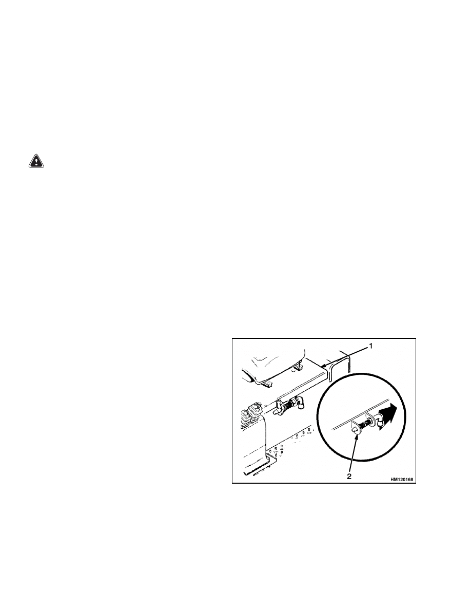
accident causes the lift truck to tip over. A sliding
latch mechanism on the front hood panel locks the
front panel to the frame for lift truck operation. See
Figure 2. The sliding latch unlocks the front hood
panel from the frame so that the hood can be raised
to the open position for access to the battery.
The latch mechanism must operate correctly before
the lift truck can be operated. The latch must not
be worn and must fully engage the frame. The front
hood panel must be locked in the closed position
when the lift truck is operated. If the latch mecha-
nism does not lock the hood in the closed position, do
not operate the lift truck.
1.
HOOD
2.
LATCH
Figure 2. Battery Restraint Latch
The rear hood panel can be removed by removing the
two capscrews that hold the panel in place on the two
brackets. See Figure 3. A handle to disconnect the
2
100 SRM 793
Hood and Seat Assembly Repair
battery is located to the right of the operator seat and
toward the back of the front hood panel. This handle
is an emergency disconnect that permits the operator
to quickly disconnect the battery while on the seat of
the lift truck. The hood must be opened to reconnect
the battery.
1.
REAR HOOD PANEL
2.
SEAT
3.
OPERATOR RESTRAINT
4.
FRONT HOOD PANEL
5.
LATCH
6.
LEFT ACCESS PANEL
7.
RIGHT ACCESS PANEL
8.
FLOOR PLATE
9.
FENDER - (RIGHT SHOWN)
10. VALVE COVER
11. COUNTERWEIGHT
12. PIN
13. REAR HOOD PANEL BRACKET
(1 OF 2 SHOWN)
14. FRONT HOOD PANEL HINGE
(1 OF 2 SHOWN)
15. FRONT HOOD PANEL LIFT
HANDLE
Figure 3. Hood and Seat Assembly
3
Counterweight Repair
100 SRM 793
The hood, seat belt, seat, and seat mount are all parts
of the operator restraint system. Checks and adjust-
ments for the operator restraint system are described
in the Operating Manual and the section Periodic
Maintenance 8000 SRM 798.
The seat assembly slides on seat rails that are fas-
tened to the hood by four capscrews. A lever at the
left front side of the base controls the adjustment of
the seat to the forward and backward positions.
The optional semi-suspension seat assembly includes
an adjustable back support. A knob handle on the
lower right side of the seat allows the operator to tilt
and adjust the back support portion of the seat to a
maximum angle of 3 degrees forward and 12 degrees
backward. A weight adjustment control lever is on
the right side of the seat, on the back support portion.
The seat can be adjusted to support a weight range
of 60 to 120 kg (132 to 264 lb).
All seats have a seat switch installed in the bottom
cushion that senses pressure. When the operator is
not on the seat, the seat switch opens and stops the
operation of the lift truck.
REMOVE
1.
Disconnect the battery connector. See Figure 3.
2.
Disconnect the electrical connector to the seat
switch. Remove the four capscrews that fasten
the seat base to the hood. Lift the seat assembly
from the hood.
3.
Remove the capscrews that fasten the front hood
panel to the hinges on the frame. Lift the panel
from the lift truck.
4.
Remove the capscrews that fasten the rear hood
panel to the brackets on the counterweight. Lift
the panel from the lift truck.
INSTALL
1.
Install the rear hood panel by aligning the two
holes on the panel to the holes on the brackets
which are located on the counterweight. See Fig-
ure 3. Insert and tighten the two capscrews that
join the rear hood panel to the counterweight.
2.
Place the front hood panel onto the lift truck. Be
sure the holes on the panel line up with the holes
on the hinges found on the frame. Insert and
tighten the capscrews to secure the front hood
panel to the truck frame.
3.
Place the seat on the front hood panel and align
the holes. Set the four capscrews into the holes
and tighten as needed. Connect the electrical
connector to the seat switch.
4.
Connect the battery connector.
Counterweight Repair
REMOVE
WARNING
Do not operate the lift truck if the capscrews
for the counterweight are not installed. When
the capscrews are removed, the counterweight
can fall from the lift truck.
1.
Remove the battery. See the section Periodic
Maintenance 8000 SRM 798 for removal of the
battery.
2.
Remove the overhead guard as described in Over-
head Guard Repair.
3.
Remove the rear hood cover and battery connec-
tor mounting plate assembly.
WARNING
The counterweight is very heavy. Make sure
the sling, chain, eyebolts, and crane or lifting
device has the capacity to lift the counter-
weight. See Table 1.
4.
Install eyebolts in the holes where the overhead
guard fastens to the counterweight.
See Fig-
ure 4. Attach a chain or sling to the eyebolts. Use
a crane or other lifting device to hold the weight
of the counterweight. Make sure the sling, chain,
eyebolts, and crane or lifting device has the ca-
pacity to lift the counterweight. See Table 1.
4
100 SRM 793
Counterweight Repair
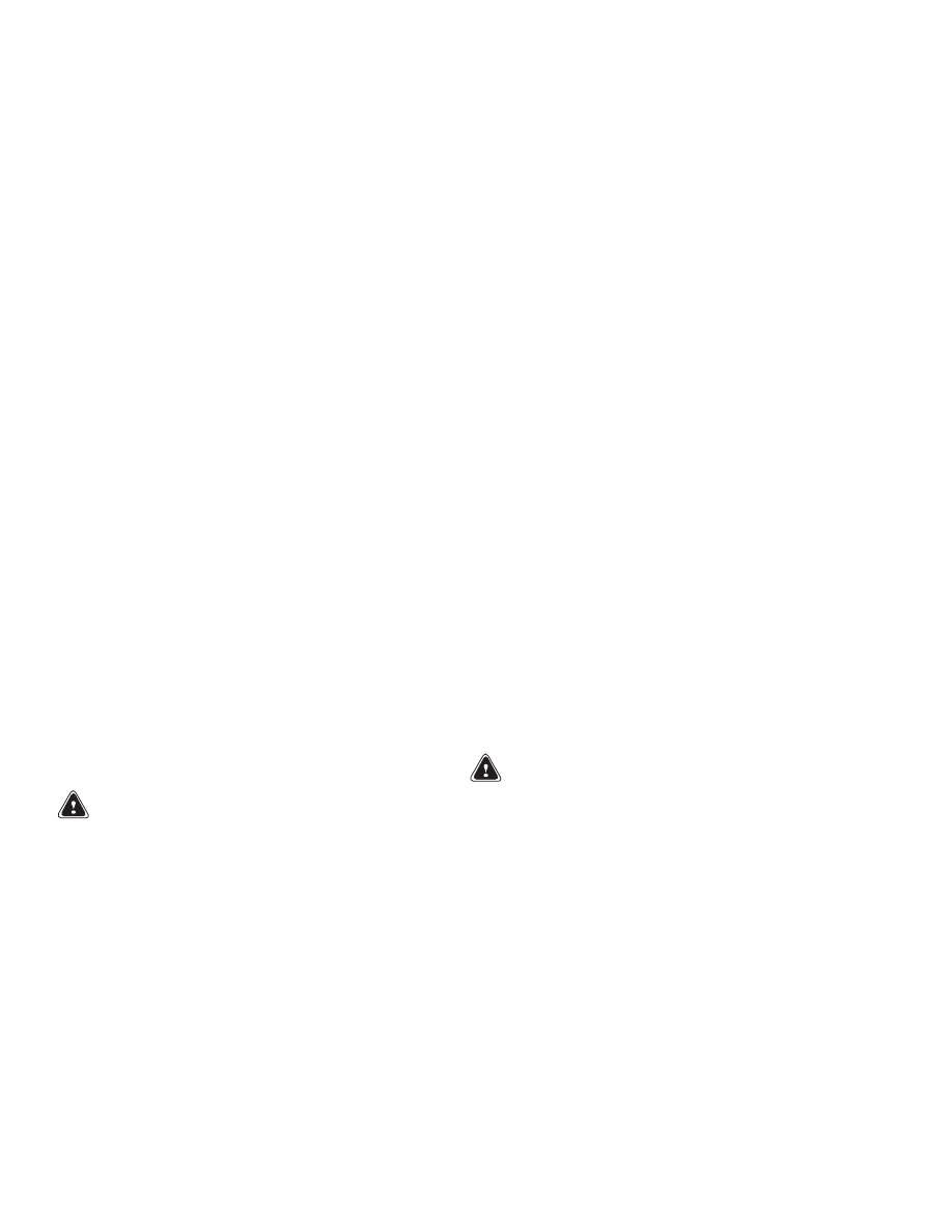
1.
COUNTERWEIGHT
2.
INSTALL EYEBOLTS HERE TO LIFT
COUNTERWEIGHT
3.
MOUNT HOLES
Figure 4. Counterweight
Table 1. Weight of Counterweights
A1.00XL (A20XL)
504 to 554 kg
(1111 to 1222 lb)
A1.25XL (A25XL)
677 to 727 kg
(1493 to 1603 lb)
A1.50XL (A30XL)
815 to 865 kg
(1797 to 1907 lb)
5.
Access to the two capscrews that hold the coun-
terweight to the frame is at the bottom inside of
the battery compartment. Access to the nuts is
from under the counterweight. Remove the two
capscrews, flat washers, lockwashers, and nuts
that hold the counterweight to the frame. Use
a crane or lifting device to lift the counterweight
away from the frame.
INSTALL
WARNING
The counterweight is very heavy. Make sure
the sling, chain, eyebolts, and crane or lifting
device has the capacity to lift the counter-
weight. See Table 1.
1.
Use a crane to lift the counterweight into posi-
tion. The lift points for the counterweight are
not at the center of gravity of the counterweight.
Some assistance will be required to engage the
attachment points on the frame. The counter-
weight engages two vertical plates on the frame.
These plates hold the counterweight in position
on the lift truck.
2.
Install the two capscrews, flat washers, lock-
washers, and nuts that hold the counterweight
to the frame. Tighten the capscrews to 320 N•m
(236 lbf ft).
3.
Disconnect the sling or chain. Remove the eye-
bolts from the counterweight.
4.
Install the battery.
5.
Install the overhead guard as described in Over-
head Guard Repair. Install the hood and seat as-
sembly.
5

Hydraulic Tank Repair
100 SRM 793
Hydraulic Tank Repair
INSPECT
Make a visual inspection of all sides of the tank. In-
spect the welds for cracks and leakage. Check for
wet areas, accumulation of dirt, and loose or miss-
ing paint caused by leakage. Areas of the tank that
are not easily seen can be checked with an inspection
mirror and a light that is approved for locations with
flammable vapors.
SMALL LEAKS, REPAIR
Use the following procedure to repair small leaks.
1.
Use steam to clean the area around the leak. Re-
move all paint and dirt around the leak.
WARNING
Do not use tools that generate sparks, heat, or
static electricity. The vapors in the tank can
cause an explosion.
2.
Apply Loctite
®
290 to the leak. Follow the in-
structions of the manufacturer.
LARGE LEAKS, REPAIR
1.
Use one of the procedures described under Clean
to clean and prepare the tank for repairs.
2.
Use acceptable welding practices to repair the
tank.
See the American National Standard
Safety In Welding and Cutting ANSI Z 49.1 -
1973.
CLEAN
WARNING
Special procedures must be followed when
large leaks or other repairs need welding or
cutting. All work must be done by authorized
personnel. If the tank is cleaned inside a build-
ing, make sure there is enough ventilation.
See the following manuals for additional infor-
mation.
• Safe Practices for Welding and Cutting Con-
tainers That Have Held Combustibles by the
American Welding Society, A6.0-65.
• Safety In Welding and Cutting, American Na-
tional Standard, ANSI Z 49.1 - 1973.
When cleaning the tank, do not use solutions that
make dangerous gases at normal temperatures or
when heated. Wear eye and face protection. Protect
the body from burns.
When cleaning with steam, use a hose with a mini-
mum diameter of 19 mm (0.75 in.). Control the pres-
sure of the steam by a valve installed at the nozzle of
the hose. If a metal nozzle is used, it must be made of
a material that does not make sparks. Make an elec-
trical connection between the nozzle and the tank.
Connect a ground wire to the tank to prevent static
electricity.
Steam Method
Use the following procedure to clean the tank with
steam.
1.
Remove all the parts from the tank. Install the
drain plug.
2.
Fill the tank 1/4 full with a solution of water and
sodium bicarbonate or sodium carbonate. Mix
0.5 kg (1 lb) per 4 liter (1 gal) of water.
3.
Mix the solution in the tank using air pressure.
Make sure all the surfaces on the inside of the
tank are flushed with the solution. Drain the
tank.
4.
Put steam into the tank until the tank does not
have odors and the metal is hot. Steam vapors
must come from all the openings.
5.
Flush the inside of the tank with boiling water.
Make sure all the loose material is removed from
the inside of the tank.
6.
Make an inspection of the inside of the tank. If it
is not clean, repeat Step 4 and Step 5 and make
another inspection. When making inspections,
use a light that is approved for locations with
flammable vapors.
7.
Put plugs in all the openings in the tank. Wait 15
minutes; then remove the inlet and outlet plugs.
Test a sample of the vapor with a special indi-
cator for gas vapors. If the amount of flammable
vapors is above the lower flammable limit, repeat
the cleaning procedures.
6

100 SRM 793
Safety Labels
Chemical Solution Method
If the tank cannot be cleaned with steam, use the
following procedure.
1.
Mix a solution of water and trisodium phosphate
or a cleaning compound with an alkali base. Fol-
low the instructions given by the manufacturer.
2.
Fill the tank with the cleaning solution. Use com-
pressed air to mix the solution in the tank.
3.
Drain the tank. Flush the inside of the tank with
hot (boiling) water. Make sure all the cleaning
compound is removed.
4.
Make an inspection of the inside of the tank.
If the tank is not clean, repeat Step 1 through
Step 3. Make another inspection of the tank.
When making inspections, use a light that is ap-
proved for locations with flammable vapors.
5.
Check the tank for flammable vapors using a spe-
cial indicator for gas vapors. If the amount of
flammable vapors is above the lower flammable
limit, repeat the cleaning procedures.
ADDITIONAL PREPARATIONS FOR
REPAIR
If nitrogen gas or carbon dioxide gas is available, pre-
pare the tank for welding using these gases. See the
manual Safe Practices for Welding and Cutting Con-
tainers That Have Held Combustibles by the Ameri-
can Welding Society, A6.0-65. If these gases are not
available, another method using water can be used
as follows.
1.
Fill the tank with water to just below the point
where the work will be done.
Make sure the
space above the level of the water has a vent.
2.
Use acceptable welding practices to repair the
tank.
See the American National Standard
Safety In Welding and Cutting ANSI Z 49.1 -
1973.
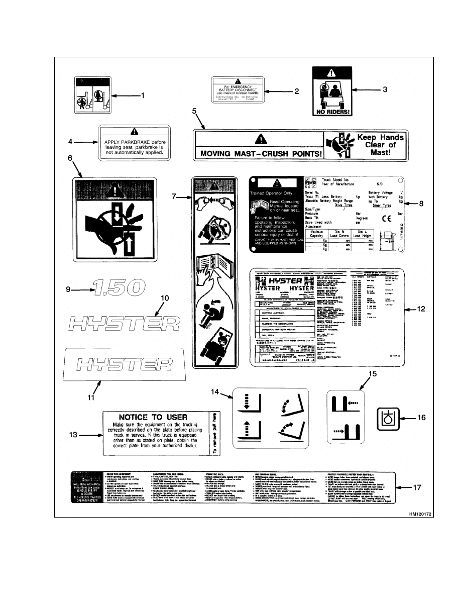
Safety Labels
WARNING
Safety labels are installed on the lift truck to
give information about operation and possible
hazards. It is important that all safety labels
are installed on the lift truck and can be read.
DO NOT add to or modify the lift truck. Any
change to the lift truck, the tires, or its equip-
ment can change the lifting capacity. The lift
truck must be rated as equipped and the name-
plate must show the new capacity rating. Con-
tact your dealer for Hyster lift trucks for a re-
placement nameplate.
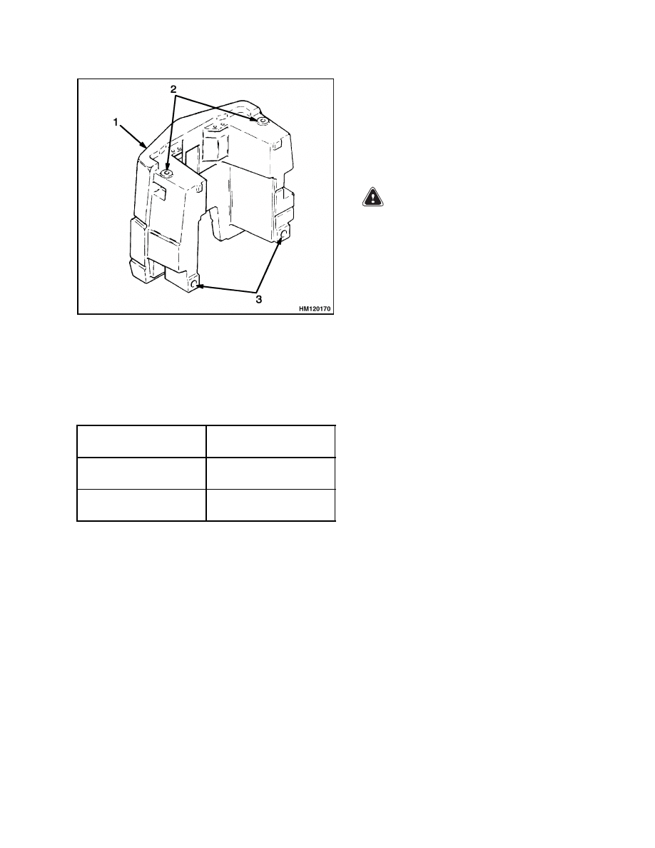
If a label must be replaced, use the following proce-
dure to install a new label. See Figure 5.
WARNING
Cleaning solvents can be flammable and toxic
and can cause skin irritation.
When using
cleaning solvents, always follow the recom-
mendations of the manufacturer.
1.
Make sure the surface is dry and has no oil or
grease. Do not use solvent on new paint. Clean
the surface of old paint with a cleaning solvent.
2.
Remove the paper from the back of the label. Do
not touch the adhesive surface.
3.
Carefully hold the label in the correct position
above the surface. The label cannot be moved af-
ter it touches the surface. Make sure that all air
is removed from under the label, and the corners
and edges are tight.
7
Safety Labels
100 SRM 793
Figure 5. Location of Labels (Sheet 1 of 2)
8
100 SRM 793
Safety Labels
Figure 5. Location of Labels (Sheet 2 of 2)
9
Battery Specifications
100 SRM 793
Legend for Figure 5
1.
MAST WARNING
2.
EMERGENCY BATTERY DISCONNECT
3.
NO RIDER
4.
PARKBRAKE WARNING
5.
MAST WARNING
6.
MAST PINCH POINT WARNING
7.
OPERATOR RESTRAINT
8.
CAPACITY PLATE
9.
MODEL LABEL
10. LOGO - (MAST AND SIDE ACCESS PANELS)
11. LOGO - (COUNTERWEIGHT)
12. PATENT AND TRADEMARKS
13. NAMEPLATE TAG
14. HOIST AND TILT
15. AUXILIARY FUNCTION - SIDESHIFT
16. HYDRAULIC OIL FILL
17. OPERATOR WARNING
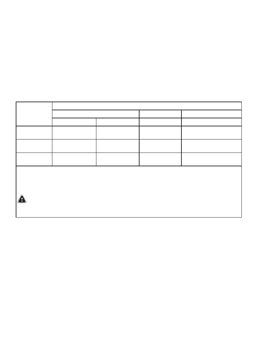
Battery Specifications
Battery Size
Minimum/Maximum
Maximum
Minimum/Maximum
Model
Length
Width
Height
Weight
A1.00XL
(A20XL)
486/497 mm
(19.1/19.5 in.)
825/830 mm
(32.5/32.6 in.)
678 mm
(26.7 in.)
450/800 kg
(992/1764 lb)
A1.25XL
(A25XL)
486/497 mm
(19.1/19.5 in.)
825/830 mm
(32.5/32.6 in.)
678 mm
(26.7 in.)
450/800 kg
(992/1764 lb)
A1.50XL
(A30XL)
486/497 mm
(19.1/19.5 in.)
825/830 mm
(32.5/32.6 in.)
678 mm
(26.7 in.)
620/800 kg
(1367/1764 lb)
The clearance between the battery (lifting eyes) and the hood determines the maximum battery height.
NOTE:
Minimum gap is 4 mm (0.18 in.) and maximum gap is 18 mm (0.71 in.) for the size of the battery com-
partment. The battery specification tables show the maximum size tolerances that will permit the battery to
still fit into the battery compartment. The clearance between the battery lifting eyes and the hood determines
the minimum battery height.
WARNING
The battery must fit the battery compartment so the battery restraint system will operate cor-
rectly.
10

TECHNICAL PUBLICATIONS
100 SRM 793
3/00 Printed in United Kingdom
Document Outline
- toc
- tables
Wyszukiwarka
Podobne podstrony:
1482632 8000SRM0798 (03 2000) UK EN
1482623 1800SRM0803 (03 2000) UK EN
1482617 1600SRM0797 (03 2000) UK EN
1482620 1600SRM0796 (03 2000) UK EN(1)
1586982 0100SRM1177 (03 2005) UK EN
1554631 2000SRM1085 (03 2004) UK EN
897953 1600SRM0639 (03 2005) UK EN
1598459 1900SRM1213 (03 2005) UK EN
1596602 0100SRM1200 (07 2005) UK EN
897956 1900SRM0642 (03 2005) UK EN
897457 8000SRM0488 (03 1992) UK EN
897986 1600SRM0658 (03 1997) UK EN
więcej podobnych podstron