
PERIODIC
MAINTENANCE
A1.00-1.50XL (A20-30XL) [C203]
PART NO. 1482632
8000 SRM 798

SAFETY PRECAUTIONS
MAINTENANCE AND REPAIR
• When lifting parts or assemblies, make sure all slings, chains, or cables are correctly
fastened, and that the load being lifted is balanced. Make sure the crane, cables, and
chains have the capacity to support the weight of the load.
• Do not lift heavy parts by hand, use a lifting mechanism.
• Wear safety glasses.
• DISCONNECT THE BATTERY CONNECTOR before doing any maintenance or repair
on electric lift trucks.
• Disconnect the battery ground cable on internal combustion lift trucks.
• Always use correct blocks to prevent the unit from rolling or falling. See HOW TO PUT
THE LIFT TRUCK ON BLOCKS in the Operating Manual or the Periodic Mainte-
nance section.
• Keep the unit clean and the working area clean and orderly.
• Use the correct tools for the job.
• Keep the tools clean and in good condition.
• Always use HYSTER APPROVED parts when making repairs. Replacement parts
must meet or exceed the specifications of the original equipment manufacturer.
• Make sure all nuts, bolts, snap rings, and other fastening devices are removed before
using force to remove parts.
• Always fasten a DO NOT OPERATE tag to the controls of the unit when making repairs,
or if the unit needs repairs.
• Be sure to follow the WARNING and CAUTION notes in the instructions.
• Gasoline, Liquid Petroleum Gas (LPG), Compressed Natural Gas (CNG), and Diesel fuel
are flammable. Be sure to follow the necessary safety precautions when handling these
fuels and when working on these fuel systems.
• Batteries generate flammable gas when they are being charged. Keep fire and sparks
away from the area. Make sure the area is well ventilated.
NOTE:
The following symbols and words indicate safety information in this
manual:
WARNING
Indicates a condition that can cause immediate death or injury!
CAUTION
Indicates a condition that can cause property damage!

Periodic Maintenance
Table of Contents
TABLE OF CONTENTS
General ...............................................................................................................................................................
How to Move Disabled Lift Truck .................................................................................................................
How to Tow Lift Truck...............................................................................................................................
How to Put Lift Truck on Blocks...................................................................................................................
How to Raise Load Wheels .......................................................................................................................
How to Raise Steer Wheels .......................................................................................................................
Safety Procedures When Working Near Mast..................................................................................................
Maintenance Schedule.......................................................................................................................................
Maintenance Procedures Every 8 Hours or Daily............................................................................................
Checks Before Operation...............................................................................................................................
Hydraulic System ......................................................................................................................................
Battery .......................................................................................................................................................
Battery Restraint System .........................................................................................................................
Operator Restraint System.......................................................................................................................
Mast, Forks, and Lift Chains....................................................................................................................
Lift Chain Adjustments ............................................................................................................................
Tires and Wheels .......................................................................................................................................
Check Operation ............................................................................................................................................
Gauges and Horn.......................................................................................................................................
Control Levers and Pedals........................................................................................................................
Lift System Operation...............................................................................................................................
Service Brakes ...........................................................................................................................................
Parking Brake ...........................................................................................................................................
Steering System ........................................................................................................................................
Maintenance Procedures Every 500 Hours or 2 Months .................................................................................
Hydraulic Tank Breather ..............................................................................................................................
Wheel Nut Torques ........................................................................................................................................
Master Drive Unit (MDU) .............................................................................................................................
Mast................................................................................................................................................................
Lift Chains .....................................................................................................................................................
Forks...............................................................................................................................................................
Safety Labels..................................................................................................................................................
Brake Fluid ....................................................................................................................................................
Other Lubrication ..........................................................................................................................................
Electrical Inspection ......................................................................................................................................
Contactors..................................................................................................................................................
Motor Brushes ...........................................................................................................................................
Maintenance Procedures Every 2000 Hours or Yearly ....................................................................................
Hydraulic System ..........................................................................................................................................
Change Hydraulic Oil Filter .....................................................................................................................
Change Hydraulic Oil ...............................................................................................................................
Brake Shoes ...................................................................................................................................................
Steering System.............................................................................................................................................
Master Drive Unit .........................................................................................................................................
Adjust Service Brakes ...................................................................................................................................
Adjust Parking Brake....................................................................................................................................
Lift and Tilt System Leak Check ......................................................................................................................
Lift System.....................................................................................................................................................
Tilt System .....................................................................................................................................................
Battery Maintenance .........................................................................................................................................
How to Charge Battery..................................................................................................................................
©2002 HYSTER COMPANY
i

Table of Contents
Periodic Maintenance
TABLE OF CONTENTS (Continued)
How to Change Battery .................................................................................................................................
Battery Size Specifications............................................................................................................................
Wheel and Tire Maintenance ............................................................................................................................
General ...........................................................................................................................................................
How to Change Tires .....................................................................................................................................
Solid Rubber Tires on Pneumatic Wheels ....................................................................................................
Remove Wheels From Lift Truck..............................................................................................................
Remove Solid Rubber Tire From Pneumatic Wheel ................................................................................
Install Solid Rubber Tire on Pneumatic Wheel .......................................................................................
Wheels, Install...........................................................................................................................................
This section is for the following models:
A1.00-1.50XL (A20-30XL) [C203]
ii

8000 SRM 798
General
General
WARNING
When working on or near the mast or carriage,
see Safety Procedures When Working Near
Mast in this section.
This section contains a Maintenance Schedule and
the instructions for maintenance and inspection.
The Maintenance Schedule has time intervals for in-
spection, lubrication, and maintenance. The time
intervals are based on a normal operation. A nor-
mal operation is considered to be one 8-hour shift
per day in a relatively clean environment on an im-
proved surface. Multiple shifts, dirty operating con-
ditions, etc., will require a reduction in the recom-
mended time periods in the Maintenance Schedule.
Your Hyster lift truck dealer has the facilities and
trained personnel to do the maintenance. A complete
program of inspection, lubrication, and maintenance
will help your lift truck perform efficiently and oper-
ate over a longer period of time.
Some users have service personnel and facilities to
do the items listed in the Maintenance Schedule.
Service Manuals are available from your Hyster lift
truck dealer to help users who do their own mainte-
nance.
Do not make repairs or adjustments unless specifi-
cally authorized to do so.
Put the lift truck on a level surface. Lower the car-
riage and forks, apply the parking brake, and turn
the key switch to OFF. Open the access panels and
inspect for leaks and conditions that are not normal.
Clean any oil spills. Make sure that lint, dust, paper,
and other materials are removed from the compart-
ments.
HOW TO MOVE DISABLED LIFT TRUCK
How to Tow Lift Truck
WARNING
Do not operate a lift truck that needs repairs.
Immediately report the need for repairs. If re-
pair is necessary, put a DO NOT OPERATE tag
in the operator’s area. Remove the key from
the key switch.
WARNING
Use extra care when moving a lift truck during
the following conditions:
• Brakes do not operate correctly.
• Steering does not operate correctly.
• Tires are damaged.
• Traction conditions are bad.
• The lift truck must be moved on a steep
grade.
If the steering pump motor does not operate,
steering control of the lift truck can be slow.
This can make the control of the lift truck dif-
ficult. If there is no electrical power, steering
can be difficult. Do not tow the lift truck if
there is no power. Poor traction can cause the
disabled lift truck or towing vehicle to slide.
Steep grades will require additional brake
force to stop the lift truck.
Never carry a disabled lift truck unless the lift
truck MUST be moved and cannot be towed.
The lift truck used to carry the disabled lift
truck MUST have a rated capacity equal to
or greater than the weight of the disabled lift
truck. The capacity must be for a load center
equal to half the width of the disabled lift
truck. See the capacity plate of the disabled
lift truck for the approximate total weight.
The forks must extend the full width of the
disabled lift truck. Center the weight of the
disabled lift truck on the forks and be careful
not to damage the under side of the lift truck.
1.
The towed lift truck must have an operator.
2.
Tow the lift truck slowly.
3.
Raise the carriage and forks approximately
30 cm (12 in.) from the surface. Install a chain
to prevent the carriage and mast channels from
moving.
4.
If another lift truck is used to tow the disabled
lift truck, that lift truck must have an equal or
larger capacity than the disabled lift truck.
5.
Use a towing link made of steel that attaches to
the tow pins in the counterweights of both lift
trucks.
1
General
8000 SRM 798
HOW TO PUT LIFT TRUCK ON BLOCKS
How to Raise Load Wheels
WARNING
The lift truck must be put on blocks for some
types of maintenance and repair. The removal
of the following assemblies will cause large
changes in the center of gravity: mast and load
axle, battery, and counterweight. When the lift
truck is put on blocks, put additional blocks in
the following positions:
a. Before removing the mast and load wheels,
put blocks under the rear of the frame so
the lift truck cannot fall backward nor to
the side.
b. Before removing the battery and/or the
counterweight, put blocks under the mast
assembly so the lift truck cannot fall for-
ward.
Put the lift truck on blocks only if the surface
is solid, even, and level. Make sure that any
blocks used to support the lift truck are solid,
one-piece units. Put blocks in front and back of
the tires to prevent movement of the lift truck.
NOTE:
Some lift trucks have lifting eyes. These lift
points can be used to raise the lift truck so blocks can
be installed.
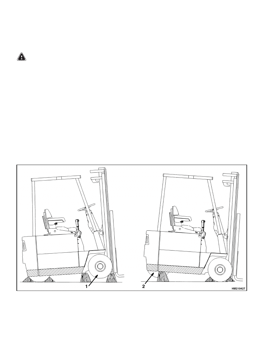
1.
Put blocks on each side (front and back) of the
steering tire to prevent movement of the lift
truck. See Figure 1.
2.
Use a hydraulic jack under the side of the frame
near the front. Make sure the jack has a capacity
equal to at least half the weight of the lift truck.
See the capacity plate.
3.
Put a block under each outer mast channel.
4.
Put additional blocks under the frame behind the
drive tires.
1.
LOAD TIRES
2.
STEER TIRE
Figure 1. Put Lift Truck on Blocks
2

8000 SRM 798
Safety Procedures When Working Near Mast
How to Raise Steer Wheels
1.
Apply the parking brake.
Put blocks on both
sides (front and back) of the drive tires to pre-
vent movement of the lift truck.
2.
Use hydraulic jacks to raise the steering tire.
Make sure that the jacks have a capacity of at
least 2/3 of the total weight of the lift truck as
shown on the capacity plate.
3.
Put the jacks under the rear of the frame to raise
the lift truck. Put blocks under the frame to sup-
port the lift truck.
Safety Procedures When Working Near Mast
The following procedures must be used when inspect-
ing or working near the mast. Additional precautions
and procedures can be required when repairing or re-
moving the mast.
WARNING
Mast parts are heavy and can move. Distances
between parts are small.
Serious injury or
death can result if part of the body is hit by
parts of the mast or the carriage.
• Never put any part of the body into or under
the mast or carriage unless all parts are com-
pletely lowered or a safety chain is installed.
Also make sure that the power is off and the
key is removed. Put a DO NOT OPERATE tag
in the operator’s compartment. Disconnect
the battery on electric lift trucks and put a
tag or lock on the battery connector.
• Be careful of the forks.
When the mast is
raised, the forks can be at a height to cause
an injury.
• Do NOT climb on the mast or lift truck at any
time. Use a ladder or personnel lift to work
on the mast.
• Do NOT use blocks to support the mast weld-
ments nor to restrain their movement.
• Mast repairs require disassembly and re-
moval of parts and can require removal
of the mast or carriage. Follow the repair
procedures in the correct Service Manual
section for the mast.
WHEN WORKING NEAR THE MAST, ALWAYS:
1.
Lower the mast and carriage completely. Push
the lift/lower control lever forward and make
sure there is no movement in the mast. Make
sure that all parts of the mast that move are
fully lowered.
OR
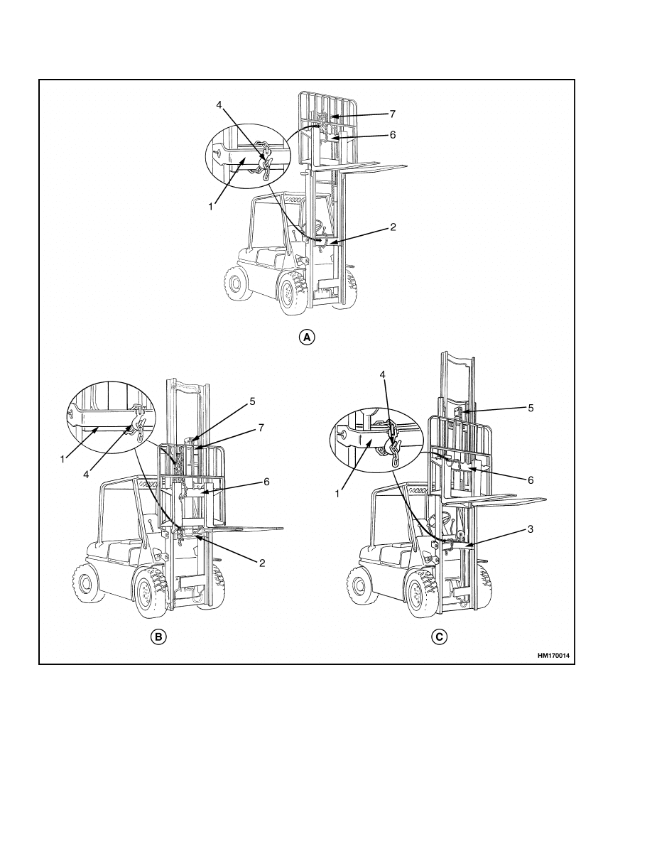
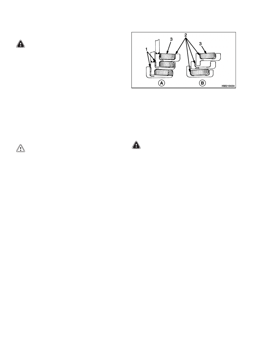
2.
If parts of the mast must be in raised position,
install a safety chain to restrain the moving parts
of the mast. Connect moving parts to a part that
does not move. Follow these procedures:
a. Put the mast in a vertical position.
b. Raise the mast to align the bottom cross-
member of the weldment that moves in the
outer weldment with a crossmember on the
outer weldment. On the two-stage and free-
lift mast, the moving part is the inner weld-
ment. On the three-stage mast, it is the in-
termediate weldment. See Figure 2.
c.
Use a 9.4 mm (3/8 in.) minimum safety chain
with a hook to fasten the crossmembers to-
gether so the movable member cannot lower.
Put the hook on the back side of the mast.
Make sure the hook is completely engaged
with a link in the chain.
Make sure the
safety chain does not touch lift chains or
chain sheaves, tubes, hoses, fittings, or other
parts on the mast.
d. Lower the mast until there is tension in the
safety chain and the free-lift cylinder (free-
lift, three-stage masts only) is completely re-
tracted. If running, stop the engine. Apply
the parking brake. Install a DO NOT RE-
MOVE tag on the safety chain(s).
e.
Install another safety chain [9.4 mm (3/8 in.)
minimum] between the top or bottom cross-
member of the carriage and a crossmember
on the outer weldment.
3.
Apply the parking brake. After lowering or re-
straining the mast, shut off the power and re-
move the key. Put a DO NOT OPERATE tag in
the operator’s compartment. Disconnect the bat-
tery on electric lift trucks and put a tag or lock
on the battery connector.
3
Safety Procedures When Working Near Mast
8000 SRM 798
A. TWO-STAGE MAST
B. FREE-LIFT MAST
C. THREE-STAGE MAST
1.
OUTER WELDMENT
2.
INNER WELDMENT
3.
INTERMEDIATE WELDMENT
4.
HOOK
5.
FREE-LIFT CYLINDER
6.
CROSSMEMBER
7.
CROSSMEMBER
Figure 2. Two-Stage, Free-Lift, and Three-Stage Masts
4
8000 SRM 798
Maintenance Schedule
Maintenance Schedule
The Maintenance Schedule has two time periods in
which the mechanic can perform the maintenance.
For lift trucks operated less than 8 hours each day,
use the 1-DAY, 2-MONTH, and 1-YEAR period sched-
ule. For lift trucks operated more than 8 hours each
day, use the 8-HOUR, 500-HOUR, and 2000-HOUR
schedule.
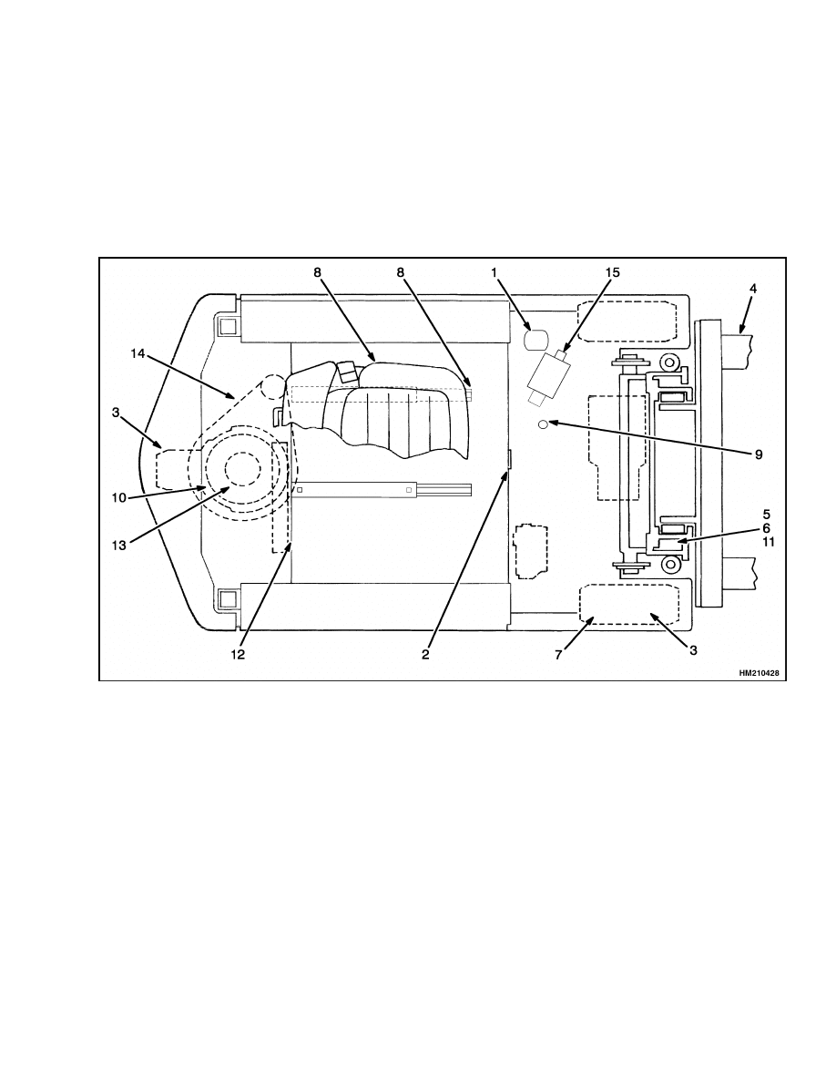
The approximate locations of the items indicated in
the Maintenance Schedule are shown in Figure 3.
The maintenance schedules are made according to
the maximum service intervals for average condi-
tions. Inspect and lubricate more frequently when
operating in dirty or difficult conditions.
Figure 3. Maintenance Points
5

Maintenance Schedule
8000 SRM 798
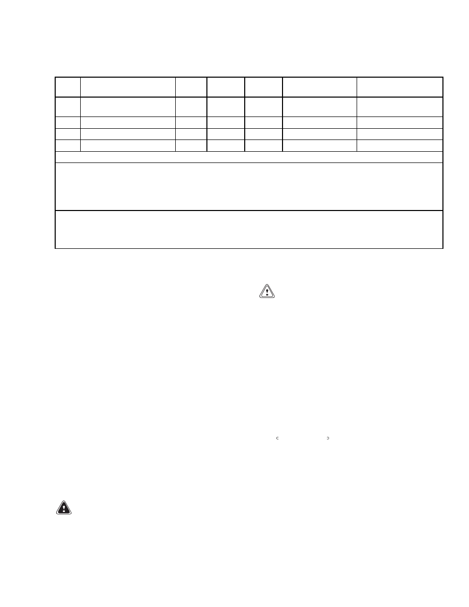
Table 1. Maintenance Schedule
Item
No.
Item
8 hr/
1 day
500 hr/
1 yr
2000 hr/
1 yr
Procedure or
Quantity
Specification
1
Hydraulic Oil (Tank)
(Total System)
Oil Leaks
X
C
12.5 liter (13.2 qt)
14.5 liter (15.3 qt)
Check for leaks
18 C (0 F) and above
SAE 10W
API CC or CC/SE
2
Battery
Restraint Latch
X
1
X
Check Electrolyte
Level
Check Operation
3
Wheels and Tires
X
Check Condition
See Capacity Plate
4
Forks
X
Check Condition
5
Lift Chains
X
Check Condition
6
Upright
X
Check Operation
Gauges, Horn, Lights, and
Alarms
X
Check Operation
Operation of Electronic
Controller
X
Check Operation
See Parts Manual
7
Service Brakes
X
X
Check Operation
Check Brake Lining
See Parts Manual
8
Seat Belt and Rails
X
Check Condition
Parking Brake
Adjustment
X
L
X
Check Operation
Check Adjustment
Silicone Lubricant
on Linkage
See Service Manual
Brake Fluid
X
0.25 liter (0.26 qt) SAE J-1703 Brake Fluid
9
Hydraulic Tank Breather
X
Clean or Replace
1
See Note
3
See Parts Manual
10
Master Drive Unit
X
4
C
4.5 liter (4.8 qt)
SAE 80W-90
MIL-L-2105B, AGL-5
11
6
5
Mast
Sliding Surfaces
Lift Chains
L
L
Multipurpose Grease
2
Engine Oil, 20W-20
12
Contactors
X
Check Condition
13
Motor Brushes
X
Check Condition
3
Wheel Nut Torque
X
140 N•m (103 lbf ft)
Hood Hinges and Latches
L
As Necessary
Multipurpose Grease
2
Silicone Lubricant
on Linkage
X=Check
C=Change
L=Lubricate
NOTES:
1
Give battery equalization charge approximately monthly, but not more than each week.
2
Multipurpose grease with 4% Molybdenum Disulfide.
3
Very dirty conditions required daily check and clean.
4
It is recommended that the oil be changed after the first 500 hours of operation of a new unit.
*Recommended service intervals are based on a normal application in a clean environment. Applications
involving contaminated environment, poor ground conditions, intense usage at high performance levels, or
other abnormal conditions will require more frequent servicing. At your request, your Hyster dealer will
advise you of the appropriate service interval on an application survey.
6
8000 SRM 798
Maintenance Procedures Every 8 Hours or Daily
Table 1. Maintenance Schedule (Continued)
Item
No.
Item
8 hr/
1 day
500 hr/
1 yr
2000 hr/
1 yr
Procedure or
Quantity
Specification
Safety Labels
X
Replace as
Necessary
See Parts Manual
15
Hydraulic Filter
C
1
See Parts Manual
14
Steering Chain
L
As Necessary
Multipurpose Grease
2
8
Seat Rails
L
As Necessary
Multipurpose Grease
2
X=Check
C=Change
L=Lubricate
NOTES:
1
Give battery equalization charge approximately monthly, but not more than each week.
2
Multipurpose grease with 4% Molybdenum Disulfide.
3
Very dirty conditions required daily check and clean.
4
It is recommended that the oil be changed after the first 500 hours of operation of a new unit.
*Recommended service intervals are based on a normal application in a clean environment. Applications
involving contaminated environment, poor ground conditions, intense usage at high performance levels, or
other abnormal conditions will require more frequent servicing. At your request, your Hyster dealer will
advise you of the appropriate service interval on an application survey.
Maintenance Procedures Every 8 Hours or Daily
Inspect the lift truck every 8 hours or daily before
use. Put the lift truck on a level surface. Lower the
carriage and forks, turn the key switch to OFF, and
apply the parking brake. If repair is required, put a
tag in the operator’s area that indicates the lift truck
cannot be operated. DO NOT operate a lift truck un-
til the problems are corrected.
CHECKS BEFORE OPERATION
Make the following checks:
• Oil level in the hydraulic tank
• Electrolyte and specific gravity of the battery
• Make sure the battery is clean and the correct size
and weight for the lift truck
• Operation of the battery restraint and latch mech-
anism
• Condition of the wheels and tires
• Condition of the forks, carriage, mast, and over-
head guard
• Leaks in the hydraulic system
Hydraulic System
WARNING
At operating temperature, the hydraulic oil is
HOT. Do not permit the oil to contact the skin
and cause a burn.
CAUTION
Do not permit dirt to enter the hydraulic sys-
tem when the oil level is checked or the filter
is changed.
Never operate the pump without oil in the hy-
draulic system. The operation of the hydraulic
pump without oil will damage the pump.
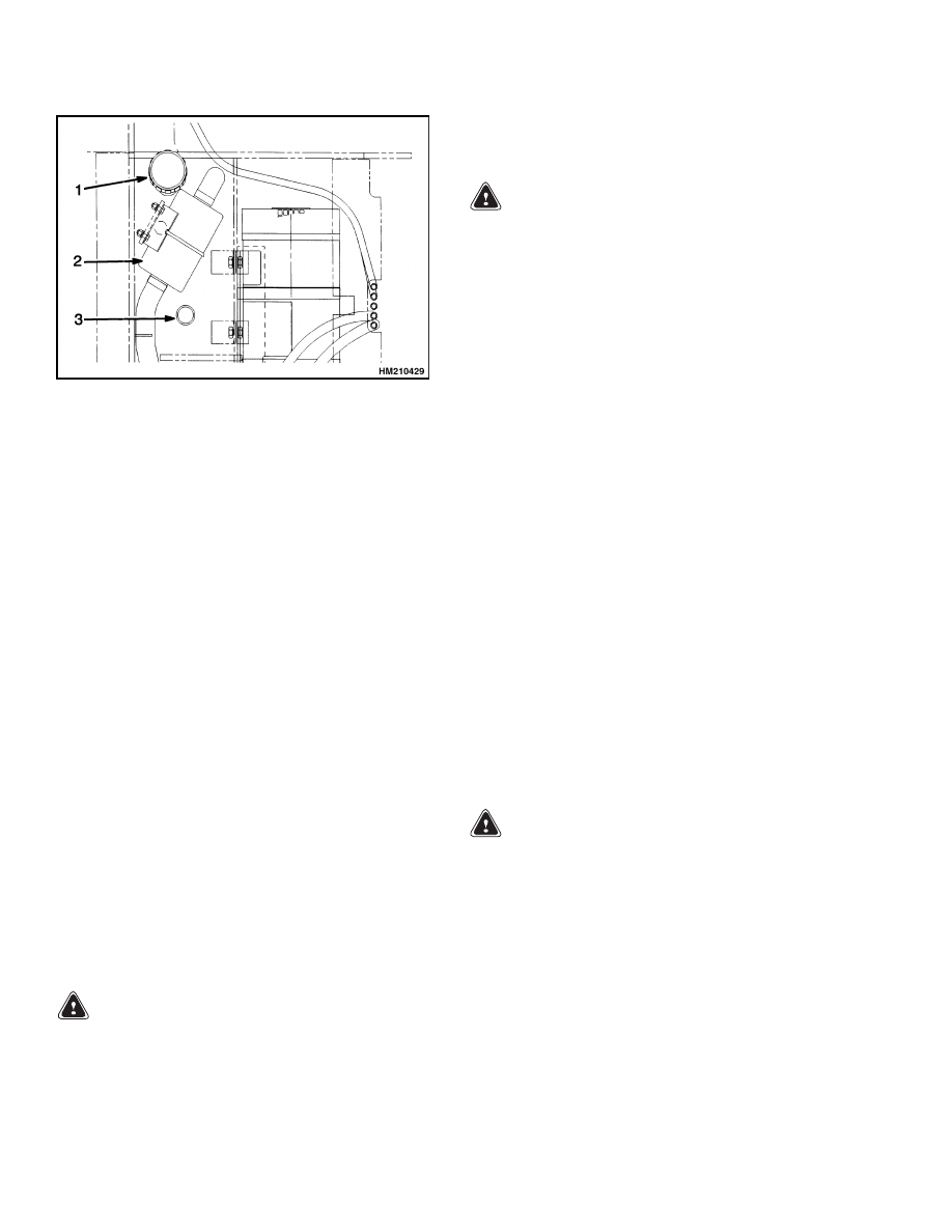
Check the hydraulic oil level when the oil is at operat-
ing temperature, the carriage is lowered, and the key
switch is OFF. See Figure 4. Add hydraulic oil only
as needed. If more hydraulic oil is added than the
FULL level, hydraulic oil will leak from the breather
during operation. The oil level indicated by the dip-
stick is most accurate when the oil temperature is 53
to 93 C (130 to 200 F).
Inspect for leaks in the hydraulic system. Inspect the
condition of the hydraulic hoses and tubes under the
floor plate and on the mast.
Check the hydraulic system for leaks and damaged
or loose components.
7
Maintenance Procedures Every 8 Hours or Daily
8000 SRM 798
1.
HYDRAULIC TANK DIPSTICK
2.
HYDRAULIC FILTER
3.
HYDRAULIC TANK BREATHER
Figure 4. Check Hydraulic Oil
Battery
Make sure the battery voltage and the battery weight
is within the maximum and minimum weight shown
on the capacity plate.
Keep the battery case, top cover, and the area for the
battery clean and painted. Leakage and corrosion
from the battery can cause a malfunction in the elec-
tric controls of the lift truck. Use a water and sodium
bicarbonate solution (soda) to clean the battery and
the battery area. Keep the top of the battery clean,
dry, and free of corrosion.
Make sure the battery is charged and has the cor-
rect voltage and ampere hour rating for the lift truck.
(See the capacity plate.)
Inspect the battery case, connector, and cables for
damage, cracks, or breaks. See the battery dealer
in the area to repair any damage. Check the level of
the electrolyte daily on a minimum of one cell. The
correct level is halfway between the top of the plates
and the bottom of the fill hole. Add only distilled
water.
Battery Restraint System
WARNING
Make sure the key switch is OFF and the park
brake is set before connecting the battery.
If the lift truck was operated with a discharged
battery, check all contactors for welded tips be-
fore a charged battery is connected.
WARNING
Do not put tools on the battery.
The acid in the electrolyte can cause injury. If
the electrolyte is spilled, use water to flush the
area. Make the acid neutral with a solution
of sodium bicarbonate (soda). Acid in the eyes
must be flushed with water immediately.
Batteries generate explosive fumes. Keep the
vents in the caps clean. Keep sparks or open
flames away from the battery area.
Do not
make a spark from the battery connections.
Disconnect the battery when doing mainte-
nance.
The battery must fit the battery compartment
so the battery restraint will operate correctly.
Use spacers to prevent the battery from moving
more than 13 mm (0.5 in.) in any direction.
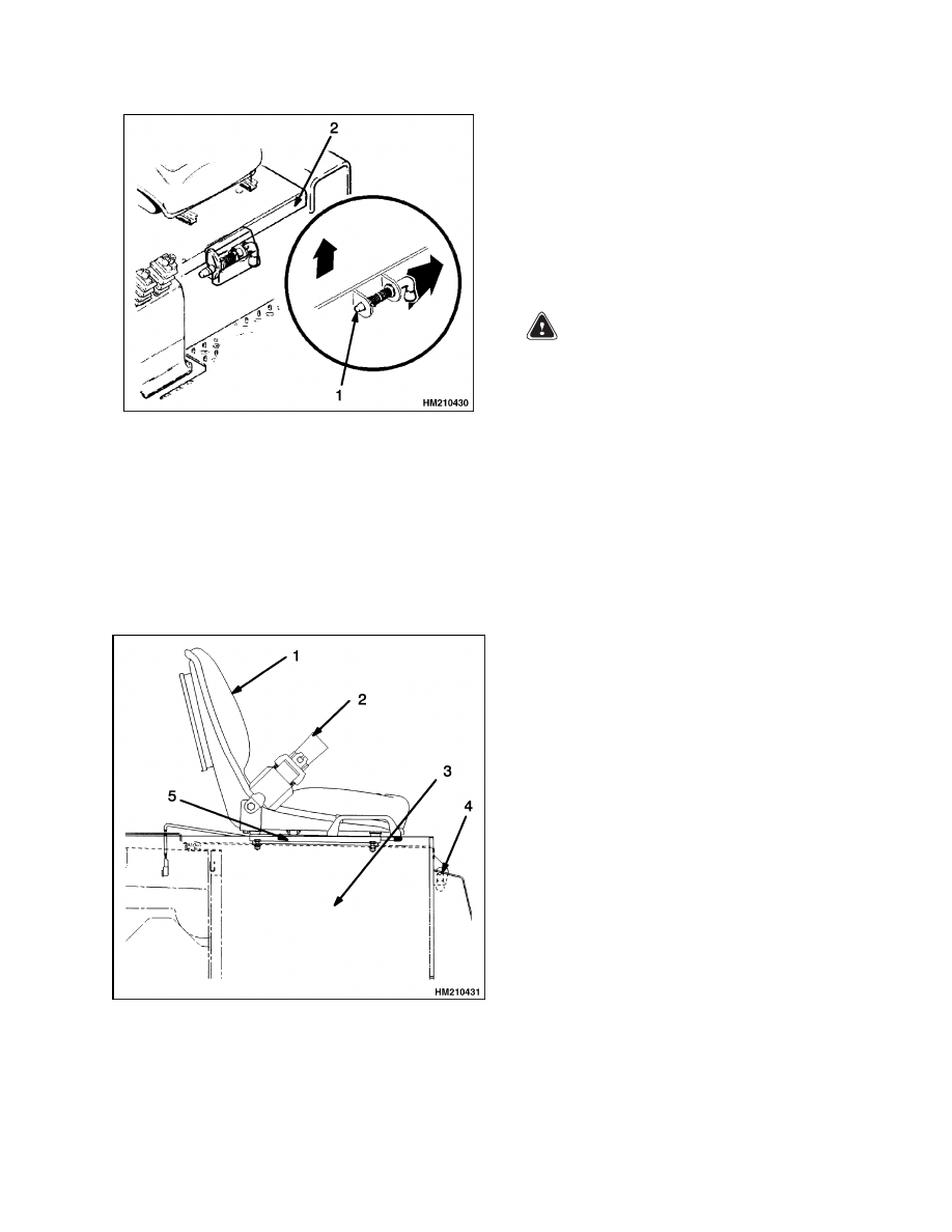
The hood assembly is also a battery restraint. See
Figure 5. The function of the battery restraint, when
the hood is correctly locked to the frame, is to hold
the battery in the battery compartment if an acci-
dent causes the lift truck to tip over. A sliding latch
mechanism on the front of the hood locks the hood to
the frame for lift truck operation. The sliding latch
unlocks the hood from the frame so the hood can be
raised to the open position for access to the battery.
The hood is also the support for the seat. A spring
brace holds the seat and hood assembly in the open
position.
WARNING
The battery restraint and its latch mechanism
must operate correctly before the lift truck is
operated.
Make sure the latch mechanism operates correctly.
Check that the latch is not worn and fully engages
the frame. The hood must be locked in the closed po-
sition when the lift truck is operated. Try to raise the
seat and hood when the hood is locked in the closed
position. If the latch mechanism does not lock the
hood in the closed position, do not operate the lift
truck.
8
8000 SRM 798
Maintenance Procedures Every 8 Hours or Daily
1.
LATCH
2.
HOOD
Figure 5. Battery Restraint
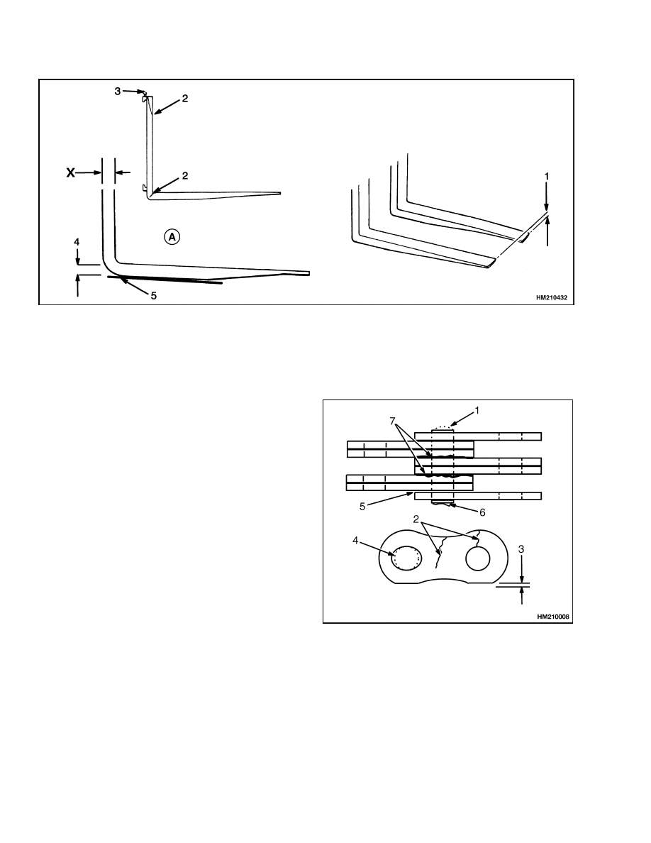
Operator Restraint System
The seat belt, seat and mount, and battery restraint
are all part of the operator restraint system. See Fig-
ure 6. Each item must be checked to make sure it is
fastened correctly, functions correctly, and is in good
condition.
1.
SEAT
2.
SEAT BELT LATCH
3.
BATTERY
COMPARTMENT
4.
HOOD LATCH
5.
RAILS
Figure 6. Check Hood Latches
Make sure the seat rails are fastened correctly at the
attachment points. The seat must lock in position on
the seat rails, but the seat must freely slide on the
seat rails when it is unlocked. The seat belt must
latch correctly. Make sure the seat belt extends and
retracts smoothly and is not worn or damaged. If you
cannot pull the seat belt from the retractor assembly,
replace the seat belt and retractor assembly.
Mast, Forks, and Lift Chains
WARNING
When working on or near the mast or carriage,
see Safety Procedures When Working Near
Mast at the front of this section.
NEVER work under a raised carriage or forks.
Lower the carriage or use blocks and chains on
the mast weldments and carriage so they can-
not move. Make sure the moving parts are at-
tached to a part that does not move.
Do not try to correct fork tip alignment by
bending the forks or adding shims.
Replace
damaged forks.
Never repair damaged forks by heating or
welding. Forks are made of special steel using
special procedures. Replace damaged forks.
Do not try to move a fork without a lifting de-
vice. Each fork can weigh 35 to 40 kg (77 to
88 lb).
1.
Inspect the welds on the mast and carriage for
cracks. Make sure that the capscrews and nuts
are tight.
2.
Inspect the channels for wear in the areas where
the rollers travel. Inspect the rollers for wear or
damage.
3.
Inspect the load backrest extension for cracks
and damage.
4.
Inspect the forks for cracks and wear. Check the
alignment of the fork tips (Figure 7). The fork tip
alignment must be within 13 mm (0.5 in.). Check
that the bottom of the fork is not worn (Figure 7).
9
Maintenance Procedures Every 8 Hours or Daily
8000 SRM 798
A. HOOK-TYPE FORK
1.
TIP ALIGNMENT = 13 mm (0.5 in.)
2.
CRACKS
3.
LATCH DAMAGE
4.
HEEL OF FORK (MUST BE 90% OF DIMENSION
X)
5.
HEEL WEAR
Figure 7. Check Forks
5.
Replace any damaged or broken parts that are
used to keep the forks locked in position.
6.
Lubricate the lift chains with 30W engine oil.
The best procedure is to remove the chains from
the lift truck and soak them in oil.
7.
Inspect the lift chains for cracks or broken links
and pins. See Figure 8.
8.
Inspect the chain anchors and pins for cracks and
damage.
9.
Make sure the lift chains are adjusted so they
have equal tension. See Lift Chain Adjustments
for adjustment procedures.
1.
WORN PIN
2.
CRACKS
3.
EDGE WEAR
4.
HOLE WEAR
5.
LOOSE LEAVES
6.
DAMAGED PIN
7.
RUST
Figure 8. Check Lift Chains
10
8000 SRM 798
Maintenance Procedures Every 8 Hours or Daily
Lift Chain Adjustments
When correctly adjusted (see Figure 9):
• The tension will be the same on each chain of the
chain set. Check tension by pushing on both chains
at the same time.
• The chain length will be correct.
• The chains must travel freely through the complete
cycle.
1.
Put a load equal to 80 to 90% of the capacity load
on the forks. Lower the forks as much as possi-
ble. Tilt the mast fully backward.
2.
Check the amount that the bottom carriage roller
extends below the inner channel of the mast. The
carriage roller must not extend more than 1/3 of
the roller diameter below the inner channel. If
the adjustment is not correct, adjust the chain
anchors.
Make sure each chain anchor is ad-
justed the same amount.
3.
Remove the load from the forks. Check the clear-
ance of the carriage when the mast is fully ex-
tended. The carriage stops must not touch the
stop on the top crossmember of the inner weld-
ment. The chains are too tight if the carriage
touches the crossmember. Put the mast in a ver-
tical position and lower the carriage completely.
If the forks do not just touch the surface, the
chains are too tight. If the chains are too tight,
adjust the chain anchors. Make sure each anchor
is adjusted the same amount. See Figure 9.
Figure 9. Lift Chain Adjustments
Legend for Figure 9
1.
TILT MAST FULLY BACKWARD
2.
CARRIAGE ROLLER
3.
FORK
4.
CARRIAGE ROLLER MUST NOT EXTEND MORE
THAN 34 mm (1.3 in.) BELOW MAST CHANNEL
NOTE:
When the chain adjustments are complete,
make sure that the threads on the nuts of the chain
anchors are completely engaged. Make sure that the
nuts on the chain anchors are not tight against the
mounts. The chain anchors must be free to move in
their sockets.
4.
Three-stage mast chain adjustment: Adjust the
main lift chains so the top of the inner weld-
ment is even with the top of the intermediate
weldment within ±1.5 mm (0.06 in.). Adjust the
free-lift chain as described in Step 3.
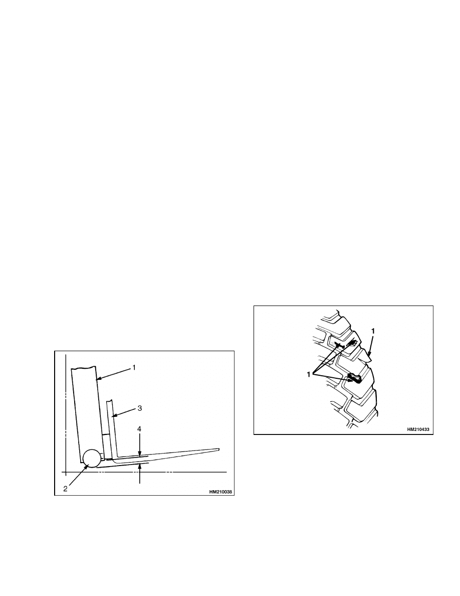
Tires and Wheels
Inspect the tires for wire, rocks, glass, pieces of
metal, holes, cuts, and other damage. See Figure 10.
Remove any object that will cause damage. Check
for loose or missing hardware. Remove any wire,
strapping, or other material that is wrapped around
the axle.
1.
CHECK TIRE FOR DAMAGE
Figure 10. Check Tires
11

Maintenance Procedures Every 8 Hours or Daily
8000 SRM 798
CAUTION
When the wheels have been installed, check
all wheel nuts after 2 to 5 hours of operation.
Tighten the nuts in a cross pattern to the cor-
rect torque value shown in the Maintenance
Schedule table. When the nuts stay tight after
an 8-hour check, the interval for checking the
torque can be extended to 500 hours.
Make sure the wheel nuts are tight. Tighten the
wheel nuts in a cross pattern to the correct torque
value shown in the Maintenance Schedule table.
CHECK OPERATION
Sit on the seat, turn the key switch to ON, and check
the following operations:
• Gauges and horn
• Lift, tilt, and attachment functions
• Parking and service brakes
• Steering system
• MONOTROL pedal or the direction control lever
and accelerator pedal
Gauges and Horn
1.
Check the operation of the gauges and horn. The
horn will operate when the key switch is OFF.
The hourmeter will operate when the key switch
is ON and the seat switch is closed.
WARNING
Make sure the key switch is OFF and the park
brake is set before connecting the battery.
2.
The battery indicator will operate when the key
switch is ON. If the battery is replaced with a
fully-charged battery, the battery indicator will
not indicate a fully-charged battery until the lift
truck has operated for a short period of time.
Tilt the mast backward until the hydraulic relief
valve operates. The battery indicator will then
indicate correctly.
Control Levers and Pedals
Check that the levers for the mast and attachment
operate as described in Table 1 of the Operating
Manual. Check that the brake operates as described
in Table 1 of the Operating Manual.
Lift System Operation
WARNING
When working on or near the mast or carriage,
see Safety Procedures When Working Near
Mast at the front of this section.
Lower the lift mechanism completely. Never al-
low anyone under a raised carriage. Do not
put any part of your body in or through the
lift mechanism unless all parts of the mast are
completely lowered and the key switch is OFF.
Do not try to locate hydraulic leaks by putting
hands on pressurized hydraulic components.
Hydraulic oil can be injected into the body by
pressure.
1.
Check for leaks in the hydraulic system. Check
the condition of the hydraulic hoses and tubes.
2.
Slowly raise and lower the mast several times
without a load. The mast components must raise
and lower smoothly in the correct sequence. The
carriage raises first, then the inner weldment
and the intermediate weldment (three-stage
masts only).
NOTE:
Parts of the mast move at different speeds
during raising and lowering.
3.
The inner weldment(s) and the carriage must
lower completely.
4.
Raise the mast 1 m (3 ft), with a capacity load.
The inner weldment(s) and carriage must raise
smoothly. Lower the mast. All moving compo-
nents must lower smoothly.
5.
With the load lowered, tilt the mast backward
and forward. The mast must tilt smoothly and
both tilt cylinders must stop evenly.
6.
Check that the controls for the attachment oper-
ate the functions of the attachment. (See symbols
by each of the controls.) Make sure all of the hy-
draulic lines are connected correctly and do not
leak.
12

8000 SRM 798
Maintenance Procedures Every 500 Hours or 2 Months
Service Brakes
WARNING
Loss of fluid from the master cylinder indicates
a leak. Repair the brake system before the lift
truck is used. Replace the brake fluid in the
system if there is dirt, water, or oil in the sys-
tem.
Check the operation of the service brakes. Push on
the brake pedal. The brakes must be applied before
the pedal reaches the floor plate. The brake pedal
must stop firmly and must not move slowly down af-
ter the brakes are applied. The brakes must apply
equally to both drive wheels with no noticeable pull
to either side.
Parking Brake
Check the operation of the parking brake. The park-
ing brake, when in good condition and correctly ad-
justed, will hold the lift truck with a capacity load on
a 15% grade [a slope of 1.5 m in 10 m (a slope of 1.5 ft
in 10 ft)]. See Adjust Parking Brake in the Mainte-
nance Procedures Every 2000 Hours or Yearly section
of this manual. Do not tighten the adjustment so the
brake is applied when the hand lever is released.
Steering System
WARNING
The steering can be difficult when the power
steering pump is not operating.
Check that the steering system operates smoothly
and gives good steering control.
Maintenance Procedures Every 500 Hours or 2 Months
NOTE: Do these procedures in addition to the 8-hour
checks.
HYDRAULIC TANK BREATHER
The hydraulic tank breather is located on the top of
the hydraulic tank next to the hydraulic tank filter.
Inspect the hydraulic tank breather. Clean or replace
the breather when it is dirty and will not permit the
easy passage of air. See Figure 14.
WHEEL NUT TORQUES
Tighten wheel nuts as required. See Wheels, Install
and Maintenance Schedule.
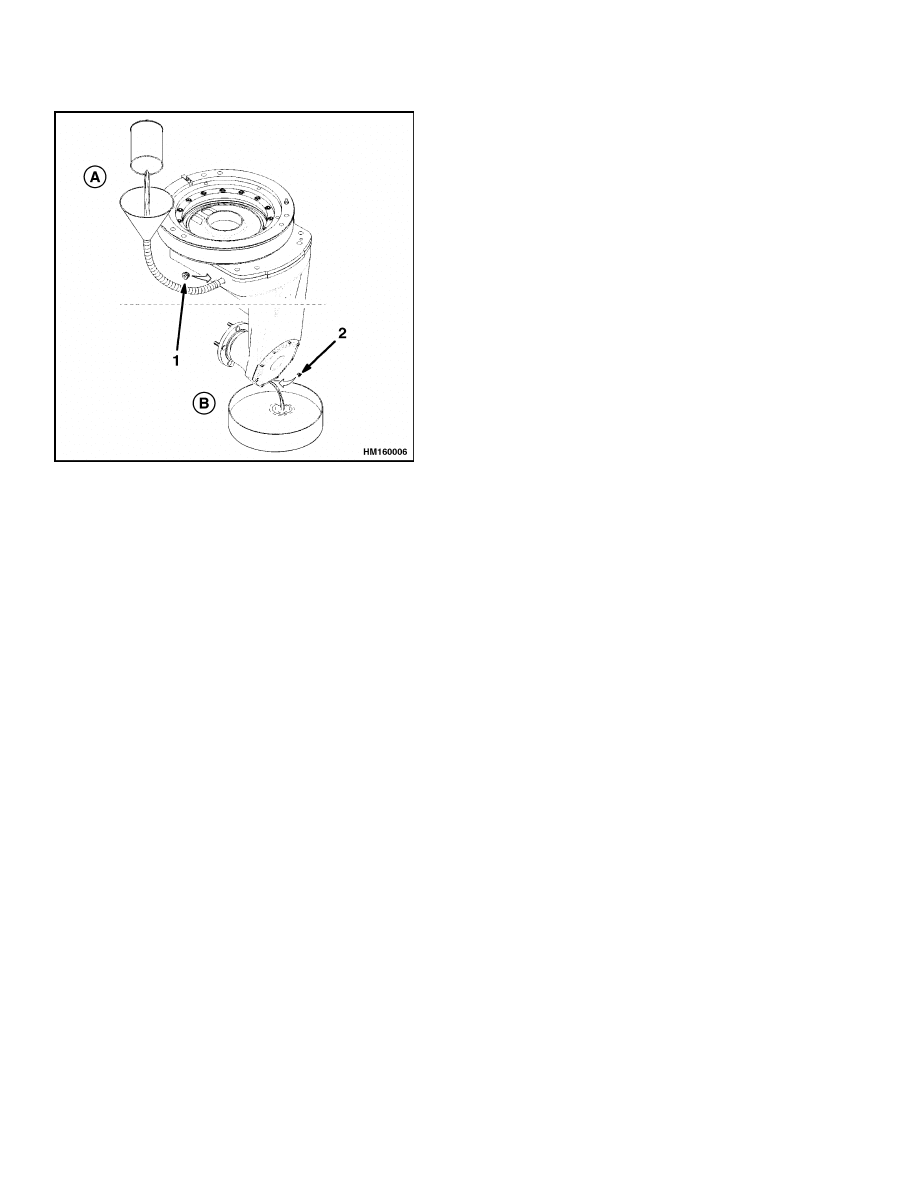
MASTER DRIVE UNIT (MDU)
WARNING
After a long period of operation, transmission
oil becomes very hot. Use heat resistant gloves
to protect against serious burns and other in-
juries.
The transmission fluid in the master drive unit must
be checked every 500 hours. It is recommended that
the fluid be changed after the initial 500 hours of a
new truck.
There are two different drive units used on this lift
truck, a ZF model ( Figure 15) or a Kordel model (
Figure 16). The MDU assembly has one oil compart-
ment. Access to the check and fill port inlet can be
gained by removing the tow pin from its slot on the
counterweight and turning the MDU counterclock-
wise until the check and fill port is visible through
the tow pin slot. The correct oil level is achieved
when it is level with the lip of the oil inlet hole. Dur-
ing filling, ensure that air does not become trapped
within the transmission. Trapped air can be removed
by turning the wheel shaft. Insert the oil inlet screw
together with a new seal ring and tighten to 22 N•m
(16.23 lbf ft).
13
Maintenance Procedures Every 500 Hours or 2 Months
8000 SRM 798
MAST
WARNING
When working on or near the mast or carriage,
see Safety Procedures When Working Near
Mast at the front of this section.
Do not work under a raised carriage. Lower
the carriage or use a safety chain to prevent
the carriage from lowering when doing main-
tenance on the mast and lift chains.
Cleaning solvents can be flammable and toxic
and can cause skin irritation.
When using
cleaning solvents, always follow the recom-
mendations of the manufacturer.
Be careful when cleaning with steam. Steam
can cause serious burns. Wear protective cloth-
ing, eye protection, and gloves. Never expose
your skin to steam.
CAUTION
DO NOT use steam or high pressure water to
clean the load rollers or the lift chains. Steam
and high pressure water can remove the lubri-
cation from the bearings in the load rollers.
Water in the bearings of the sheaves and the
link pins of chains can also shorten the service
life of these parts.
1.
Lubricate the sliding surfaces and the load roller
surfaces along the full length of the channels as
shown in Figure 11. Apply lubricant only to the
indicated surfaces.
NOTE:
The load rollers and sheaves have sealed bear-
ings that do not need additional lubrication.
2.
Lubricate the mast pivots with multipurpose
grease at the grease fittings on the pivot pins.
A. UPPER LOAD ROLLERS
B. LOWER LOAD ROLLERS
1.
LUBRICATE STRIP BEARINGS
2.
LUBRICATE LOAD ROLLER SURFACES
3.
LOAD ROLLER
Figure 11. Mast Lubrication
LIFT CHAINS
WARNING
When working on or near the mast or carriage,
see Safety Procedures When Working Near
Mast at the front of this section.
Do not work under a raised carriage. Lower
the carriage or use a safety chain to prevent
the carriage from lowering when doing main-
tenance on the mast and lift chains.
1.
Lubricate the lift chains with 30W engine oil.
The best procedure is to remove the chains from
the lift truck and soak them in oil.
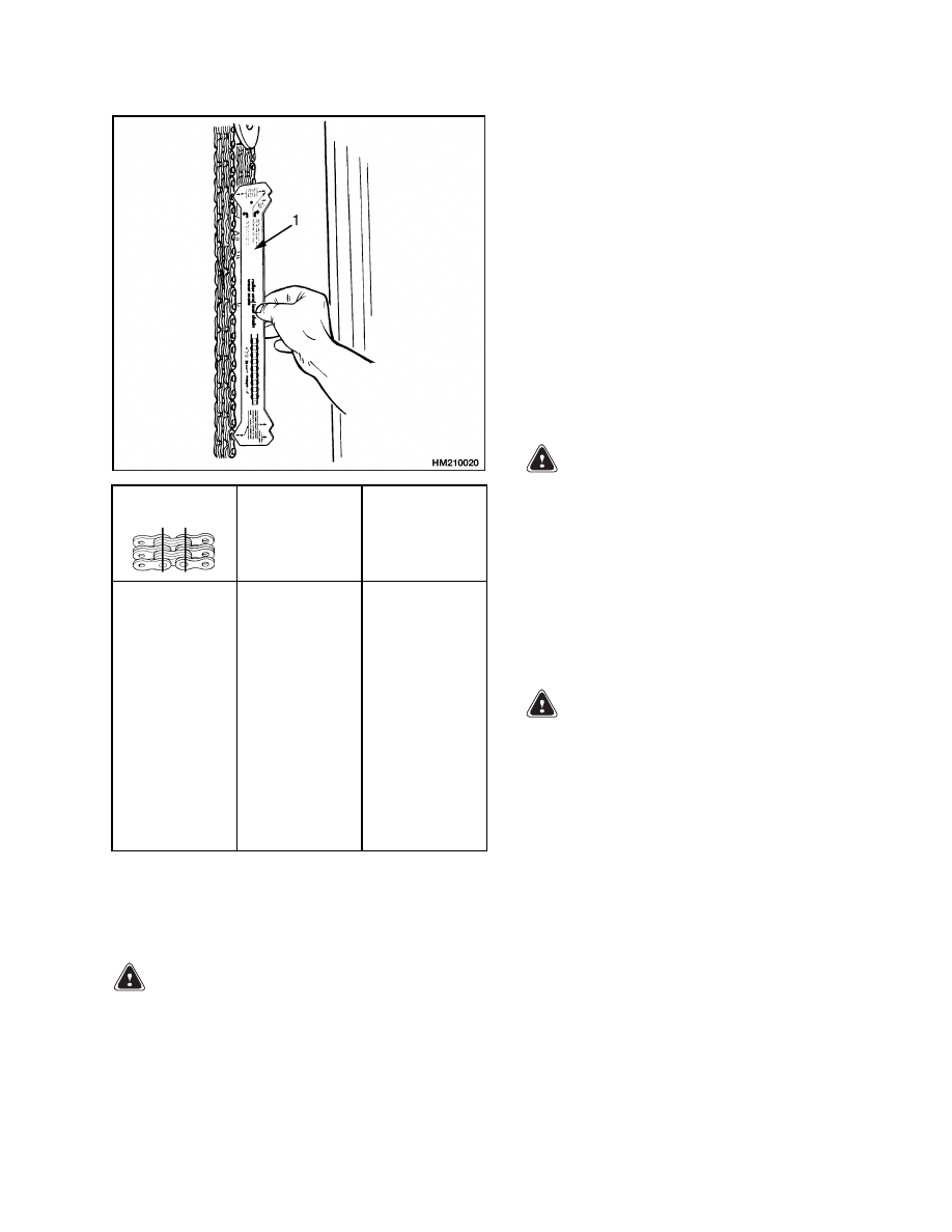
2.
If a section of chain is 3% longer than a similar
section of new chain, the chain is worn and must
be replaced. If a chain scale is available, check
the lift chains as shown in Figure 12. If a chain
scale is not available, measure 20 links of chain.
Measure from the center of a pin to the center of
another pin 20 pitches away. Compare the length
with the chart in Figure 12. Replace the chain if
the length of 20 links of the worn section is more
than the maximum wear limit.
14
8000 SRM 798
Maintenance Procedures Every 500 Hours or 2 Months
Pitch
Total Length
of 20 Links
(Pitch) of New
Chain
Wear Limit
The Maximum
Length of 20
Links
12.7 mm
(0.50 in.)
15.9 mm
(0.625 in.)
19.1 mm
(0.75 in.)
25.4 mm
(1.00 in.)
31.8 mm
(1.25 in.)
44.5 mm
(1.75 in.)
50.8 mm
(2.00 in.)
254.0 mm
(10.0 in.)
317.5 mm
(12.5 in.)
381.0 mm
(15.0 in.)
508.0 mm
(20.0 in.)
635.0 mm
(25.0 in.)
889.0 mm
(35.0 in.)
1016.0 mm
(40.0 in.)
261.6 mm
(10.3 in.)
327.0 mm
(12.88 in.)
392.4 mm
(15.45 in.)
523.25 mm
(20.6 in.)
654.1 mm
(25.75 in.)
915.7 mm
(36.05 in.)
1046.5 mm
(41.2 in.)
1.
CHAIN WEAR SCALE
Figure 12. Check Lift Chains
FORKS
WARNING
Never repair damaged forks. Do not heat, weld,
or bend the forks. Forks are made of special
steel using special methods. Replace damaged
forks.
Do not try to move a fork without a lifting de-
vice. Each fork can weigh 35 to 40 kg (77 to
88 lb).
1.
Check the heel and attachment points of the
forks with a penetrant or magnetic particle in-
spection.
2.
Inspect the forks for cracks and wear. Check the
alignment of the fork tips (1, Figure 7). The fork
tip alignment must be within 13 mm (0.51 in.).
Check that the bottom of the fork is not worn (5,
Figure 7).
SAFETY LABELS
WARNING
Safety labels are installed on the lift truck to
give information about operation and possible
hazards. It is important that all safety labels
are installed on the lift truck and can be read.
Make sure that the safety decals are clearly read-
able. Install new and correct decals if necessary. For
installation instructions, see the section Frame 100
SRM 793. See the parts manual for label locations.
BRAKE FLUID
WARNING
Loss of fluid from the master cylinder indicates
a leak. Repair the brake system before the lift
truck is used. Replace the brake fluid in the
system if there is dirt, water, or oil in the sys-
tem.
Check the brake fluid in the reservoir for the master
cylinder. Add brake fluid as necessary. Use the brake
fluid shown in the Maintenance Schedule.
OTHER LUBRICATION
Lubricate hinges, pins, linkages, cables, pedals, and
levers as necessary. Use SAE 30 oil, multipurpose
grease, or silicon lubricant (Hyster part number
251979) as needed. See the Maintenance Schedule.
15
Maintenance Procedures Every 500 Hours or 2 Months
8000 SRM 798
ELECTRICAL INSPECTION
Contactors
WARNING
Disconnect the battery connector to prevent
injury from electric shock before you make
any inspections or repairs. Attach a tag to the
connector stating DO NOT CONNECT.
WARNING
Make sure the key switch is OFF and the park
brake is set before connecting the battery.
The contact surfaces are silver alloy on a copper base.
See Figure 13. In normal operation, the contact sur-
faces become rough and black. Cleaning is not neces-
sary. Do not use a file or emery cloth on the contacts.
Replace the contacts when the surface wears through
to the copper base. Always replace the contacts in
sets. Check for equal spring tension if the contacts
do not wear evenly. See the Electrical sections for
repair procedures.
Motor Brushes
1.
Visually inspect the commutator and brushes ev-
ery 500 hours on all electric lift trucks. Make
sure the surface of the commutator is good and
the operation of the motor is correct. Worn mo-
tor brushes must be replaced before they dam-
age the surface of the commutator. Move the
brush spring to remove a brush from the brush
holder. When the brush wears within approxi-
mately 1.5 mm (0.060 in.) of where the brush
wire joins the brush, the brush must be replaced.
2.
Inspect the brush holders for burns or damage.
Make sure the brush holder is fastened tightly to
the mounts at the end of the motor. Make sure
the brushes will move freely and smoothly in the
brush holders.
3.
Check the brush springs for damage from heat
and corrosion. Replace a damaged brush spring.
See the section DC Motor Maintenance 620 SRM
294 for additional information for repair of the com-
mutator and brushes.
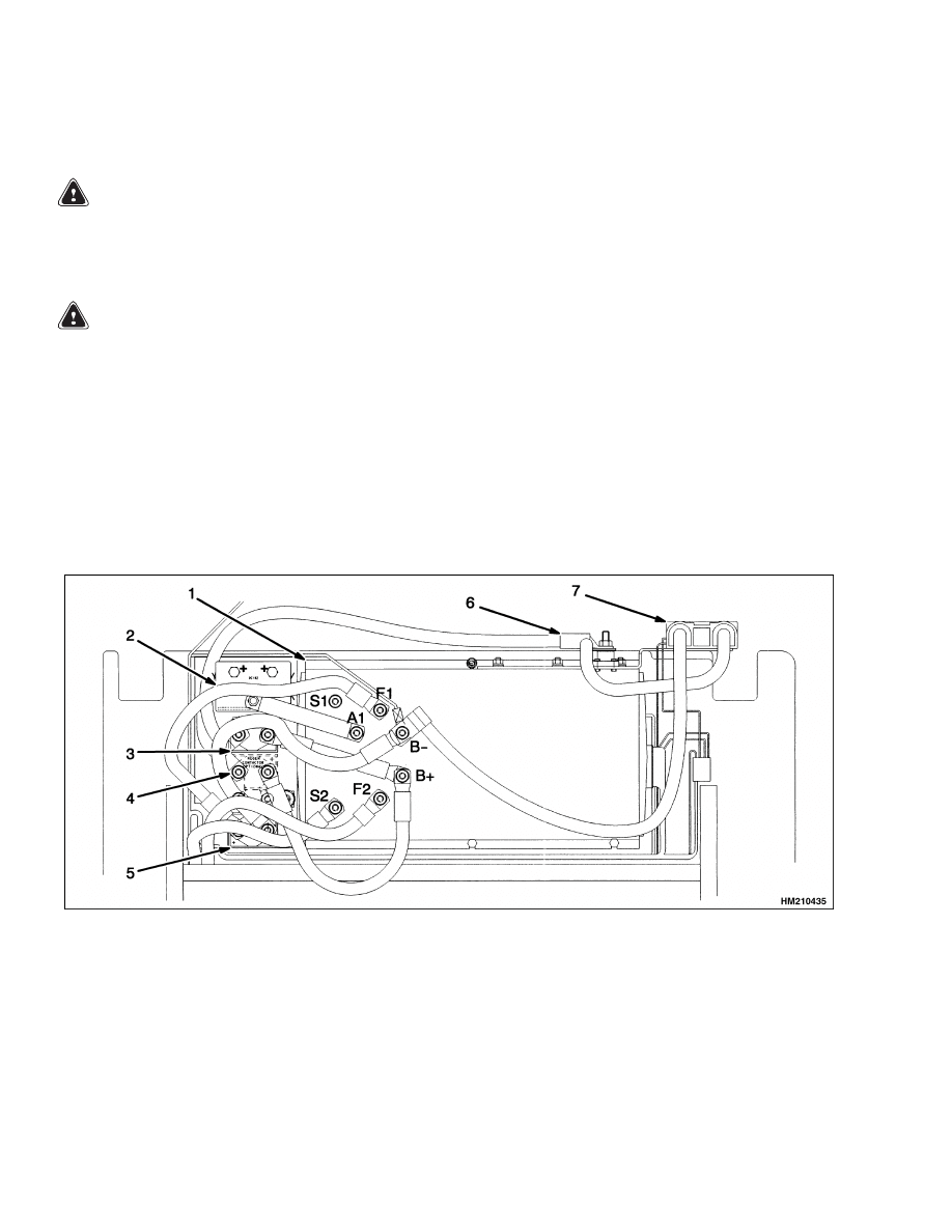
1.
MOTOR CONTROLLER
2.
FORWARD/REVERSE CONTACTOR
3.
LINE CONTACTOR
4.
REGEN CONTACTOR
5.
BYPASS CONTACTOR
6.
TRACTION FUSE
7.
BATTERY CONNECTOR
Figure 13. Sevcon Controller (Top View)
16
8000 SRM 798
Maintenance Procedures Every 2000 Hours or Yearly
Maintenance Procedures Every 2000 Hours or Yearly
HYDRAULIC SYSTEM
Change Hydraulic Oil Filter
Replace the filter element after the first 50 hours of
operation on a new lift truck. See Figure 14. Replace
the oil filter every 2000 hours or yearly after the first
50 hours. Clean the hydraulic tank breather.
1.
HYDRAULIC TANK DIPSTICK
2.
HYDRAULIC FILTER
3.
HYDRAULIC TANK BREATHER
Figure 14. Check Hydraulic Oil
Change Hydraulic Oil
WARNING
The hydraulic oil can be hot. Be careful when
you drain the hydraulic oil.
Put the lift truck on a level surface. Lower the mast.
Put a drain pan with a 13 liter (14 qt) capacity under
the hydraulic tank. Remove the drain plug on the
bottom of the hydraulic tank and drain the hydraulic
oil.
When the oil has drained, install the drain plug. Fill
the hydraulic tank with the oil described in the Main-
tenance Schedule.
BRAKE SHOES
Check the brake shoes for wear. Check the operation
of the service brakes and the parking brake. See the
repair procedures described in the section the Brake
System 1800 SRM 803.
STEERING SYSTEM
Adjust the steering chain after the first 100 hours of
operation on a new lift truck. Lubricate the chain in
the steering system every 500 hours or yearly.
MASTER DRIVE UNIT
WARNING
After a long period of operation, transmission
oil becomes very hot. Use heat-resistant gloves
to protect against serious burns and other in-
juries.
There are two different drive units used on this lift
truck, a ZF model (Figure 15) or a Kordel model (Fig-
ure 16). The MDU assembly has one oil compart-
ment. Access to the check and fill port inlet is gained
by removing the tow pin from its slot on the counter-
weight and turning the MDU counterclockwise until
the check and fill port is visible through the tow pin
slot.
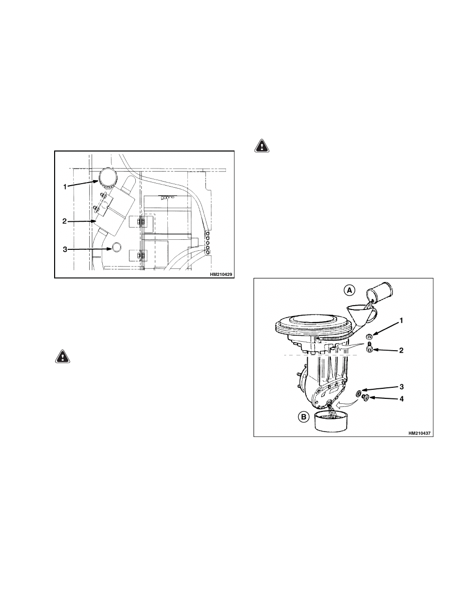
A. STEP 2 - FILL OIL
B. STEP 1 - DRAIN
OIL
1.
INLET SEAL RING
2.
INLET SCREW
3.
OUTLET SEAL
RING
4.
OUTLET SCREW
Figure 15. MDU (ZF) Lubrication
17
Maintenance Procedures Every 2000 Hours or Yearly
8000 SRM 798
A. STEP 2 - FILL OIL
B. STEP 1 - DRAIN OIL
1.
INLET SEAL RING AND SCREW
2.
OUTLET SEAL RING AND SCREW
Figure 16. MDU (Kordel) Lubrication
To drain and change the gear oil, do the following:
1.
Position a suitable oil catch container under-
neath the oil outlet screw. The container must
have a capacity of at least 5 liters.
2.
Loosen and remove the oil inlet screw and seal
ring from the fill port.
3.
Remove the oil outlet screw and seal ring again
using a 6 mm hexagon wrench. Allow the gear oil
to fully drain into an appropriate container for at
least 5 minutes.
4.
Clean magnet on the oil outlet screw and reinsert
the screw with a new seal ring. Tighten the screw
to 22 N•m (16.23 lbf ft).
5.
Fill the MDU with new gear oil through the open-
ing in the fill port inlet.
NOTE:
The correct oil level is achieved when it is
level with the lip of the oil inlet hole. During filling,
make sure that air does not become trapped within
the transmission. Trapped air can be removed by
turning the wheel shaft.
6.
Insert the oil inlet screw together with a new seal
ring and tighten to 22 N•m (16.23 lbf ft).
ADJUST SERVICE BRAKES
1.
Put the lift truck on blocks so the load wheels are
raised from the floor. The square access hole to
the brake adjustment is in the back plate of the
brake assembly.
2.
Use a brake adjuster tool to adjust the brake
shoes so the wheel and brake drum will not ro-
tate. Loosen the brake adjustment just until the
wheel and brake drum will rotate.
3.
When the adjustment is complete, remove the lift
truck from the blocks and test the operation of
the brakes. Operate the lift truck in the forward
and reverse directions.
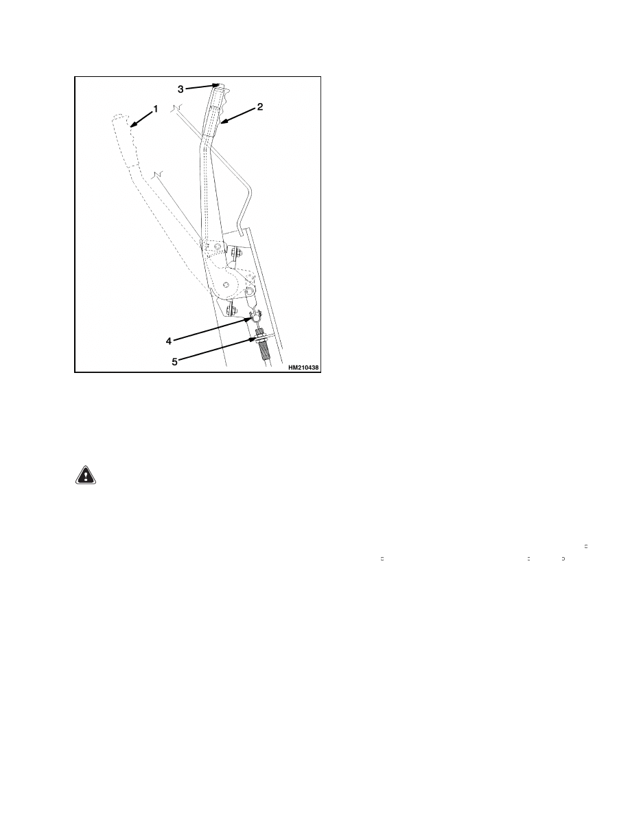
ADJUST PARKING BRAKE
Check the operation of the parking brake. The oper-
ator must adjust the parking brake so the lift truck
does not move if parked on an incline. The parking
brake, when in good condition and correctly adjusted,
will hold a lift truck with a capacity load on a 15%
grade, a slope that increases 1.5 m in 10 m (1.5 ft in
10 ft).
To adjust the park brake, make sure that the brake
lever is fully released. Adjust the outer cable to al-
low brake handle travel of four notches on the ratchet
when the brake is applied. With the brake lever in
the fully released position, adjust the nuts on both
cables so the cable ball ends are tight in the equaliz-
ing link. See Figure 17.
18
8000 SRM 798
Lift and Tilt System Leak Check
Figure 17. Park Brake Adjustment
Legend for Figure 17
1.
PARKING BRAKE LEVER OFF POSITION
2.
PARKING BRAKE LEVER ON POSITION
3.
LOCK RELEASE BUTTON
4.
EQUALIZING LINKS
5.
ADJUSTMENT NUTS
Lift and Tilt System Leak Check
LIFT SYSTEM
WARNING
Never allow anyone under a raised carriage.
Do not put any part of your body in or through
the lift mechanism unless all parts of the mast
are completely lowered, the key is removed,
and the battery is disconnected.
Do not try to find hydraulic leaks by putting
hydraulic components under pressure.
Hy-
draulic oil can be injected in to the body by
pressure.
During the test procedures for the hydraulic
system, fasten the load to the carriage with
chains to prevent it from falling.
Keep all
personnel away from the lift truck during the
tests.
1.
Operate the hydraulic system. Put a capacity
load on the forks and raise and lower the load
several times. Lower the load and tilt the mast
forward and backward several times. Check for
leaks.
2.
Raise the carriage and the load 1 m (3 ft). If
the carriage lowers slowly with the control valve
in a neutral position, there are leaks inside the
hydraulic system. The maximum speed that the
carriage is allowed to lower is 33 mm (1.2 in.)
per 10 minutes when the hydraulic oil is 30 C
(86 F). If the oil temperature is 60 C (140 F), the
maximum speed that the carriage can lower is
146 mm (5.7 in.) per 10 minutes.
3.
Check the lift cylinder for internal leaks. Remove
the load from the forks. Install a gate valve in the
supply line between the main control valve and
the mast. Put a capacity load on the forks again.
Raise the carriage 1 m (3 ft). Close the gate valve.
If the carriage or mast weldments lower slowly,
the seals in the lift cylinders have leaks.
4.
If the carriage does not move, open the gate valve
and check for movement again. If the carriage
lowers when the valve is open, check for leaks
in the hydraulic lines or fittings. If no leaks are
19
Battery Maintenance
8000 SRM 798
found, the main control valve might be damaged.
Remove the load from the forks.
TILT SYSTEM
1.
Put a capacity load on the forks. Slowly tilt the
mast forward. If the mast continues to slowly tilt
forward when the control valve is in a neutral
position, there are leaks inside the hydraulic
system. The maximum speed that the mast is
allowed to tilt forward, when there are internal
leaks in the lift system, is 1.6 degrees in 10 min-
utes. This maximum speed is measured when
the temperature of the hydraulic oil is 30 C
(86 F).
2.
If the leak rate is greater than specifications, re-
move the load from the mast. Install a valve be-
tween the port at the front of the tilt cylinder
and the hydraulic line. Put the load on the forks
again. Close the valve. If the mast tilts slowly
forward, the cylinder seals are leaking.
3.
If the mast does not move, open the gate valve
and check for movement again.
If the mast
moves forward when the gate valve is open,
check for leaks in the hydraulic lines or fittings.
If no leaks are found, the main control valve
might be damaged. Remove the load from the
forks.
Battery Maintenance
HOW TO CHARGE BATTERY
WARNING
If the lift truck was operated with a low battery,
check all contactors for welded contacts before
a charged battery is connected.
Make sure the key switch is OFF and the park
brake is set before connecting the battery.
The acid in the electrolyte can cause injury.
Use water to flush the area and make the acid
neutral with a water and soda solution. Acid in
the eyes must be flushed with water. Batteries
generate explosive fumes when they are being
charged. Keep fire, sparks, and burning mate-
rial away from the battery charger area. Avoid
sparks from the battery connections. Charge
batteries only in the special area for charging
batteries. When the battery is being charged,
keep the vent caps clear. The battery charger
area must have ventilation so explosive fumes
are removed. Open the battery cover on a cov-
ered battery. Disconnect the battery when do-
ing cleaning and maintenance.
CAUTION
Never connect the battery charger plug to the
plug of the lift truck.
You can damage the
electronic controller.
Make sure the battery
charger voltage is the correct voltage for the
battery.
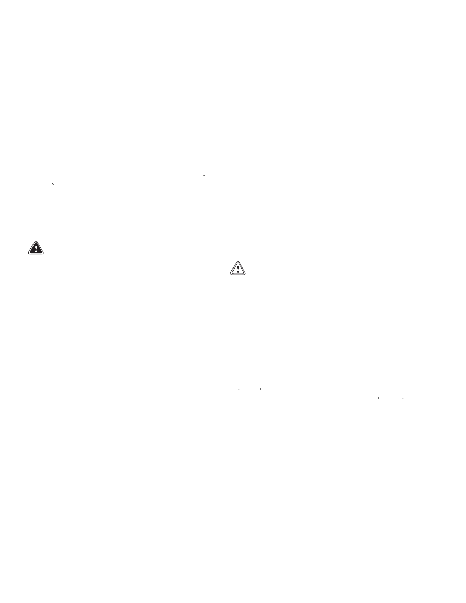
Correct use of the hydrometer (Figure 18) and proper
operation of the battery charger is important. Follow
the instructions of the charger manufacturer. Never
let the battery discharge below the minimum value
given by the battery manufacturer. A fully-charged
battery will have a specific gravity of 1.265 to 1.310 at
25 C (77 F). Never charge a battery at a rate that will
raise the electrolyte temperature above 49 C (120 F).
Never let a battery stay discharged for long periods.
20
8000 SRM 798
Battery Maintenance
Specific
Gravity
Reading
Electrolyte
Temp.
Correction
Points
Correct
Value
1.210
1.210
1.210
1.210
31 C (87 F)
27 C (80 F)
25 C (77 F)
18 C (64 F)
+0.003
+0.001
0.000
0.004
1.213
1.211
1.210
1.206
+0.001 or
0.001 for each 2 degrees C from the 25
degree base value.
Figure 18. Check Specific Gravity
NORMAL CHARGE: This charge is the charge that
is normally given to a battery that is discharged from
normal service. Many users give this charge at a
regular interval based on usage. This practice will
keep the battery fully charged if the battery is not
discharged below the limit. Always use a hydrom-
eter (Figure 18) to check the battery if the interval
charge cycle is used. Frequent charging of a battery
that has a 2/3 or more charge can decrease battery
life.
EQUALIZING CHARGE: This charge is at a low rate
and balances the charge in all of the cells. The equal-
izing charge is normally given approximately once a
month. It is a charge at a slow rate for 3 to 6 hours
in addition to the regular charging cycle.
Do NOT give an equalizing charge more than once
a week.
The most accurate specific gravity mea-
surements for a charged battery will be after an
equalizing charge. If the specific gravity difference
is more than 0.020 between cells of the battery after
an equalizing charge, there can be a defective cell.
Consult your battery dealer.
NOTE:
Many users have battery chargers that can
follow a program to automatically charge a battery
according to recommendations of the battery man-
ufacturer. Use the recommendations of the battery
manufacturer for charging the battery.
Also see the section Industrial Battery 2240 SRM 1
for additional information on the charging and main-
tenance of a battery.
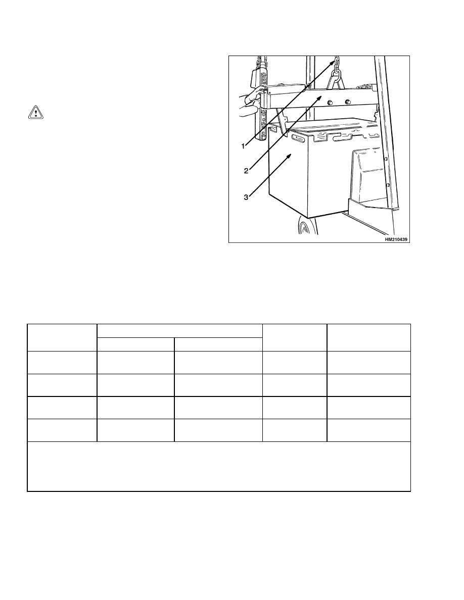
HOW TO CHANGE BATTERY
WARNING
Make sure the capacity of the crane and
spreader bar is greater than the weight of the
battery. The weight of the battery is normally
shown on the battery case. The spreader bar
must NOT be made of metal or it must have
insulated straps.
Batteries are heavy. Use care to avoid injury.
The replacement battery must fit the battery
area correctly. Use spacers to prevent the bat-
tery from moving in the battery compartment.
Make sure the weight of the replacement bat-
tery is within the maximum and minimum
weights shown on the capacity plate.
WARNING
Make sure the key switch is OFF and the park
brake is set before connecting the battery.
1.
Use the handle at the side of the operator’s seat
to disconnect the battery.
Raise the steering
wheel to its top position. Move the seat forward
to its front position. Disengage the hood latch
and raise the hood. See Figure 19.
21
Battery Maintenance
8000 SRM 798
2.
Lift the panels from both sides of the battery com-
partment.
3.
Move the connector and cables so they will not be
damaged when the battery is moved.
CAUTION
Disposal of batteries must meet local environ-
mental regulations.
4.
Use a spreader bar and crane to lift the battery
from the lift truck. When a replacement battery
is installed, make sure the battery fits the bat-
tery compartment and that it is the correct size
and weight for the lift truck. (See the capacity
plate.)
1.
LIFTING CHAIN
2.
SPREADER BAR
3.
BATTERY
Figure 19. Change Battery
BATTERY SIZE SPECIFICATIONS
Table 2. Battery Size Specifications - Type: Lead-Acid Battery
Battery Size Min./Max.
Model
Length
Width
Height Max.
Weight Min./Max.
A1.00XL
486-497 mm
(19.2-19.6 in.)
825-830 mm
(32.5-32.7 in.)
680 mm
(26.8 in.)
450-730 kg
(992-1610 lb)
A1.25XL
486-497 mm
(19.2-19.6 in.)
825-830 mm
(32.5-32.7 in.)
680 mm
(26.8 in.)
450-730 kg
(992-1610 lb)
A1.50XL
486-497 mm
(19.2-19.6 in.)
825-830 mm
(32.5-32.7 in.)
680 mm
(26.8 in.)
620-800 kg
(1367-1764 lb)
Battery
Compartment
501-504 mm
(19.7-19.8 in.)
836.8 ±2 mm
(32.94 ±0.08 in.)
The battery must fit the battery compartment so the battery restraint system will operate correctly.
NOTE:
Minimum gap is 4 mm (0.18 in.) and maximum gap is 18 mm (0.71 in.) for the size of the battery com-
partment. The battery specification tables show the maximum size tolerances that will permit the battery to
still fit into the battery compartment. The clearance between the battery lifting eyes and the hood determine
the minimum battery height.
22
8000 SRM 798
Wheel and Tire Maintenance
Wheel and Tire Maintenance
GENERAL
WARNING
The type of tire is shown on the capacity plate.
Make sure the capacity plate is correct for the
type of tires on the lift truck.
The A1.00-1.50XL (A20-30XL) series of lift trucks
use solid rubber tires that look like pneumatic tires.
Solid rubber tires made from softer or harder ma-
terial can be installed as optional equipment. The
tread on the solid rubber tires can be either smooth
or it can have lugs. Do not mix types of tires or tread
on the lift truck.
HOW TO CHANGE TIRES
See the WARNING about How to Put Lift Truck on
Blocks at the beginning of this section.
Put the lift truck on blocks. See How to Put Lift
Truck on Blocks at the beginning of this manual.
SOLID RUBBER TIRES ON PNEUMATIC
WHEELS
WARNING
Wheels must be changed and tires repaired by
trained personnel only.
Always wear safety glasses.
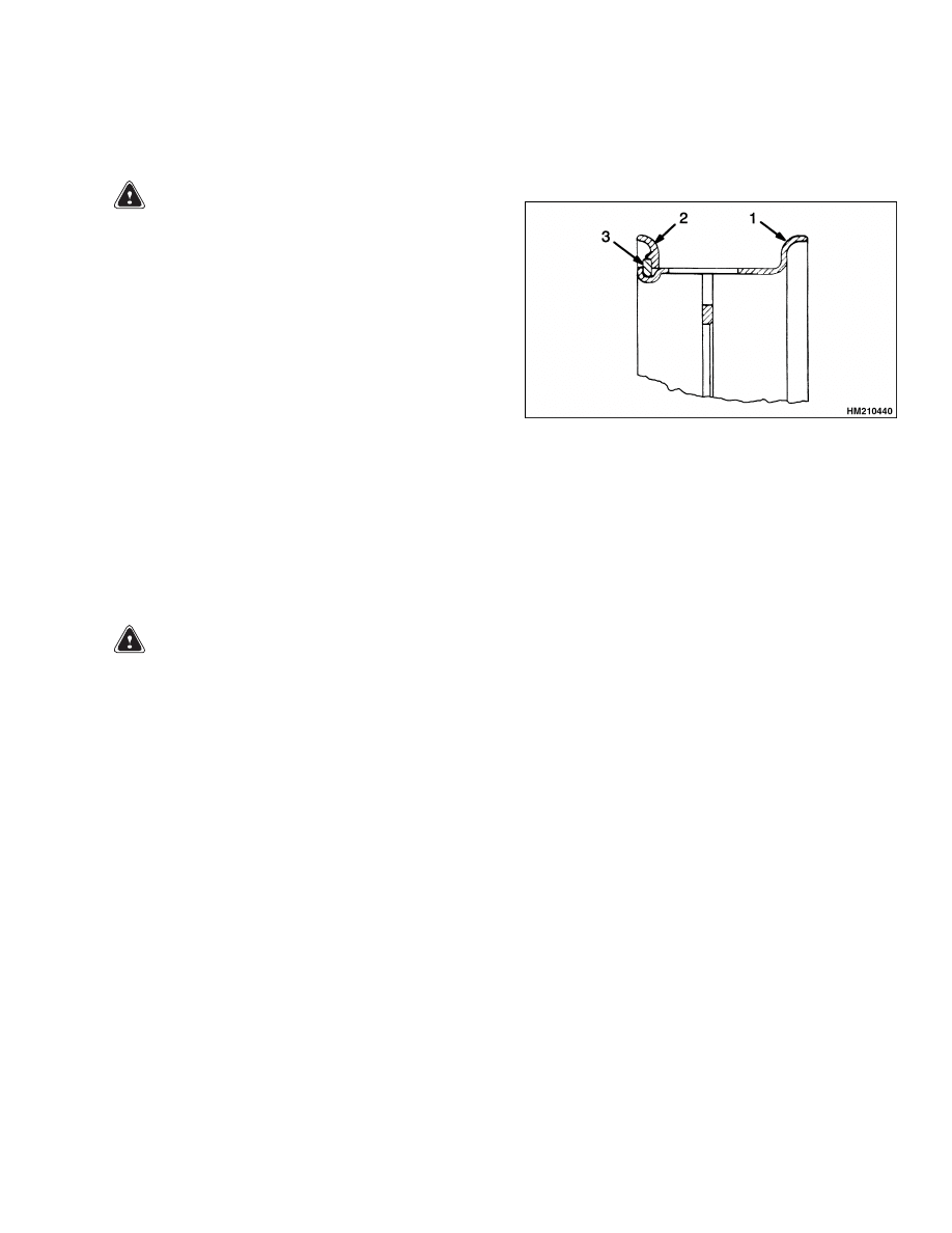
The wheel type used on this truck is shown in Fig-
ure 20.
1.
WHEEL RIM
2.
SIDE FLANGE
3.
LOCK RING
Figure 20. Three-Piece Wheel for Solid
Pneumatic Tires
Remove Wheels From Lift Truck
1.
Put the lift truck on blocks as described in How
to Put Lift Truck on Blocks at the beginning of
this manual.
2.
Remove the wheel nuts and remove the wheel
and tire from the lift truck. Lift truck tires and
wheels are heavy.
23
Wheel and Tire Maintenance
8000 SRM 798
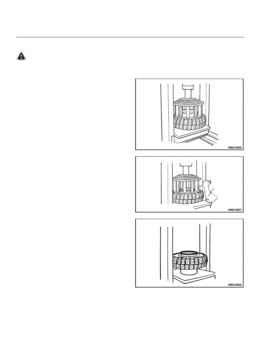
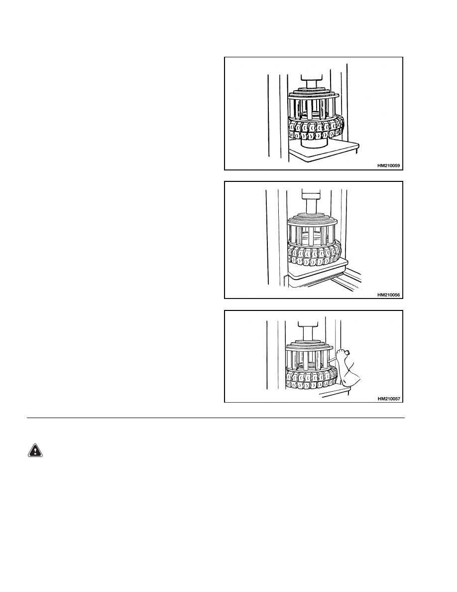
Remove Solid Rubber Tire From Pneumatic Wheel
WARNING
Keep tire tools in firm contact with the wheel. If the tool slips, it can move with enough force to
cause serious injury.
STEP 1.
Put the wheel rim on the bed of the press. Put the
cage in position on the tire. Use the press to push
the tire away from the side flange.
STEP 2.
Put the tire tool into the slot between the lock ring
and the wheel rim. Remove the lock ring and side
flange.
STEP 3.
Turn the tire over. Put a support under the wheel
rim.
Make sure the wheel rim is at least 150 to
200 mm (6 to 8 in.) from the bed of the press.
24
8000 SRM 798
Wheel and Tire Maintenance
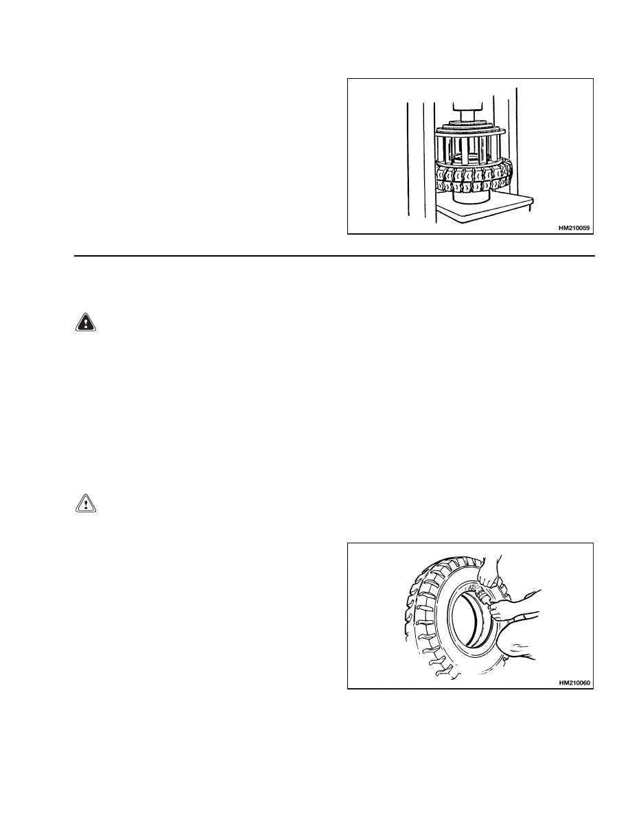
STEP 4.
Put the cage in position on the tire. Use the press to
push the tire from the wheel rim.
Install Solid Rubber Tire on Pneumatic Wheel
NOTE: The wheel type used on this truck is shown in Figure 20.
WARNING
Damage to the tire and wheel assembly and injury or death can occur if you do not do the following
procedures:
• Clean and inspect all parts of the wheel before installing the tire.
• Do NOT use any damaged or repaired wheel parts.
• Make sure that all parts of the wheel are the correct parts for the wheel assembly.
• Do NOT mix parts between different types or manufacturers of wheels.
• Do NOT mix types of tires, type of tire tread, or wheel assemblies of different manufacturers on
any one lift truck.
• Do NOT use a steel hammer on the wheel. Use a rubber, lead, plastic, or brass hammer to put
parts together. Make sure that the lock ring is in the correct position. The ends of the lock ring
must not touch. The clearance at the ends of the lock ring will be approximately 13 to 25 mm (0.5
to 1.0 in.) after it is installed. If the clearance is wrong, the wrong part has been used.
CAUTION
Too much lubricant can cause the tire to slide and move around the wheel rim.
STEP 1.
Lubricate the wheel rim and the inner surface of the
tire with tire lubricant or soap.
25
Wheel and Tire Maintenance
8000 SRM 798
STEP 2.
Put the wheel rim on the bed of the press. Put the
tire over the wheel rim. Put the cage in position on
the tire. Use the press to install the tire on the wheel
rim.
STEP 3.
Remove the cage and put the side flange and the lock
ring in position on the wheel rim. Install the cage on
the tire. Use the press to push the tire onto the wheel
rim so the side flange and lock ring can be installed.
STEP 4.
While the cage is holding the tire on the wheel rim,
install the lock ring. Use a tire tool to make sure the
lock ring is in the correct position.
Wheels, Install
WARNING
Check all wheel nuts after 2 to 5 hours of opera-
tion: when new lift trucks begin operation and
on all lift trucks when the wheels have been
removed and installed. Tighten the nuts in a
cross pattern to the correct torque value shown
in the Maintenance Schedule. When the nuts
stay tight for 8 hours, the interval for checking
the torque can be extended to 500 hours.
Install the wheel on the hub. Tighten the nuts as
shown in the Maintenance Schedule.
26

TECHNICAL PUBLICATIONS
8000 SRM 798
3/00 Printed in United Kingdom
Document Outline
- toc
- Periodic Maintenance
- Safety Precautions Maintenance and Repair
- General
- Safety Procedures When Working Near Mast
- Maintenance Schedule
- Maintenance Procedures Every 8 Hours or Daily
- Maintenance Procedures Every 500 Hours or 2 Months
- Maintenance Procedures Every 2000 Hours or Yearly
- Lift and Tilt System Leak Check
- Battery Maintenance
- Wheel and Tire Maintenance
- tables
Wyszukiwarka
Podobne podstrony:
1482635 8000SRM0804 (04 2000) UK EN
897457 8000SRM0488 (03 1992) UK EN
1482603 0100SRM0793 (03 2000) UK EN
897875 8000SRM0616 (03 2005) UK EN
1482623 1800SRM0803 (03 2000) UK EN
1482617 1600SRM0797 (03 2000) UK EN
1482620 1600SRM0796 (03 2000) UK EN(1)
897883 8000SRM0621 (03 1999) UK EN
1495208 8000SRM0949 (03 2005) UK EN
1458783 8000SRM0592 (03 2005) UK EN
1482638 8000SRM0805 (09 2005) UK EN
897778 8000SRM0586 (03 2002) UK EN
więcej podobnych podstron