CAPACITIES AND
SPECIFICATIONS
J1.60XMT, J1.80XMT, J2.00XMT,
J1.60XMT-Plus, J1.80XMT-Plus,
J2.00XMT-Plus [G160]
PART NO. 897778
8000 SRM 586

SAFETY PRECAUTIONS
MAINTENANCE AND REPAIR
• When lifting parts or assemblies, make sure all slings, chains, or cables are correctly
fastened, and that the load being lifted is balanced. Make sure the crane, cables, and
chains have the capacity to support the weight of the load.
• Do not lift heavy parts by hand, use a lifting mechanism.
• Wear safety glasses.
• DISCONNECT THE BATTERY CONNECTOR before doing any maintenance or repair
on electric lift trucks.
• Disconnect the battery ground cable on internal combustion lift trucks.
• Always use correct blocks to prevent the unit from rolling or falling. See HOW TO PUT
THE LIFT TRUCK ON BLOCKS in the Operating Manual or the Periodic Mainte-
nance section.
• Keep the unit clean and the working area clean and orderly.
• Use the correct tools for the job.
• Keep the tools clean and in good condition.
• Always use HYSTER APPROVED parts when making repairs. Replacement parts
must meet or exceed the specifications of the original equipment manufacturer.
• Make sure all nuts, bolts, snap rings, and other fastening devices are removed before
using force to remove parts.
• Always fasten a DO NOT OPERATE tag to the controls of the unit when making repairs,
or if the unit needs repairs.
• Be sure to follow the WARNING and CAUTION notes in the instructions.
• Gasoline, Liquid Petroleum Gas (LPG), Compressed Natural Gas (CNG), and Diesel fuel
are flammable. Be sure to follow the necessary safety precautions when handling these
fuels and when working on these fuel systems.
• Batteries generate flammable gas when they are being charged. Keep fire and sparks
away from the area. Make sure the area is well ventilated.
NOTE:
The following symbols and words indicate safety information in this
manual:
WARNING
Indicates a condition that can cause immediate death or injury!
CAUTION
Indicates a condition that can cause property damage!

Capacities and Specifications
Table of Contents
TABLE OF CONTENTS
Wheels and Tires................................................................................................................................................
Motors (Dual Voltage 36/48) ..............................................................................................................................
Mast Tilt Performance.......................................................................................................................................
Mast Speeds .......................................................................................................................................................
19cc Pump One- and Two-Speed Contactor..................................................................................................
19cc Pump Transistor Control ......................................................................................................................
12cc Pump One- and Two-Speed Contactor..................................................................................................
12cc Pump Transistor Control ......................................................................................................................
Mast/Tilt Drift Speeds ...................................................................................................................................
Hydraulic System...............................................................................................................................................
Torque Specifications .........................................................................................................................................
Frame .............................................................................................................................................................
Transaxle........................................................................................................................................................
Brake System.................................................................................................................................................
Wheels ............................................................................................................................................................
Steering System.............................................................................................................................................
Hydraulic System ..........................................................................................................................................
Mast/Tilt/Attachment Systems .....................................................................................................................
Accelerator Potentiometer Checks....................................................................................................................
Adjustments .......................................................................................................................................................
EV 100 LX Traction Card ..............................................................................................................................
EV 100 LX Pump Card ..................................................................................................................................
Controller Settings.............................................................................................................................................
SR/SP Traction Controller Settings - Standard With Auto Regen..............................................................
SR/SP Traction Controller Settings - Standard Without Auto Decel .........................................................
SR/SP Lift Pump Controller Settings...........................................................................................................
SR/SP Traction Controller Settings - 36V Energy Option...........................................................................
Battery Size Specifications................................................................................................................................
Type: Lead Acid Battery ...............................................................................................................................
This section is for the following models:
J1.60XMT, J1.80XMT, J2.00XMT,
J1.60XMT-Plus, J1.80XMT-Plus,
J2.00XMT-Plus [G160]
©2002 HYSTER COMPANY
i

"THE
QUALITY
KEEPERS"
HYSTER
APPROVED
PARTS
8000 SRM 586
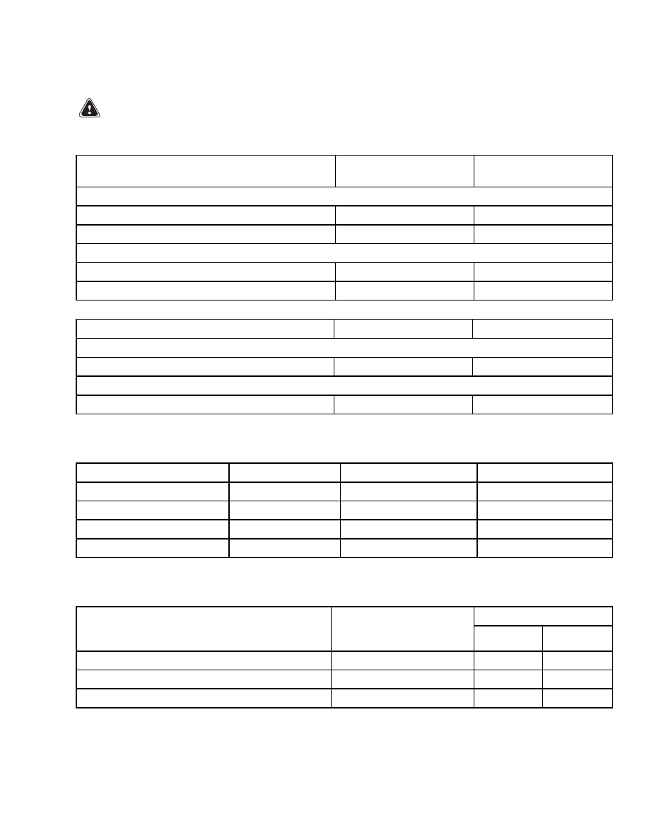
Mast Tilt Performance
Wheels and Tires
WARNING
Changing the tire type can change the capacity of the lift truck. The lift truck must be rated as
equipped. The nameplate must show the new capacity rating.
J1.60XMT, J1.80XMT, J1.60XMT-Plus,
and J1.80XMT-Plus
Tire Size
kPa (psi)
Drive Tires
Pneumatic
18 × 7-8 (16PR)
1000 kPa (145 psi)
Pneumatic Shaped Solid
18 × 7-8
N.A.
Steering Tires
Pneumatic
15 × 4.5 × 8 (12PR)
1000 kPa (145 psi)
Pneumatic Shaped Solid
15 × 4.5 × 8
N.A.
J2.00XMT and J2.00XMT-Plus
Tire Size
kPa (psi)
Drive Tires
Pneumatic Shaped Solid
200/50-10
N.A.
Steering Tires
Pneumatic Shaped Solid
15 × 4.5 × 8
N.A.
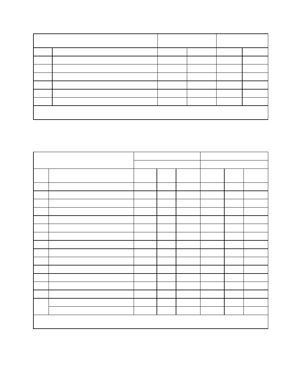
Motors (Dual Voltage 36/48)
Traction
Hydraulic
Steering
Rotation (Drive End)
Two-Direction
Counterclockwise
Counterclockwise
Winding
Separate
Series
Permanent Magnet
Number of Brushes
4
4
4
Approximate Weight
34.5 kg (76 lb)
34 kg (75 lb)
13.6 kg (30 lb)
Mast Tilt Performance
Amps (Maximum)
Mast Height
Time ±1 Second Full
Back to Forward
w/Rated Load
36 Volts
48 Volts
Up to 4572 mm (180 in.)
6-7 Seconds
260
260
4597.4 mm (181 in.) to 6096 mm (240 in.)
8-9 Seconds
260
260
Above 6096 mm (240 in.)
1 Second/Degree
260
260
1
Mast Speeds
8000 SRM 586
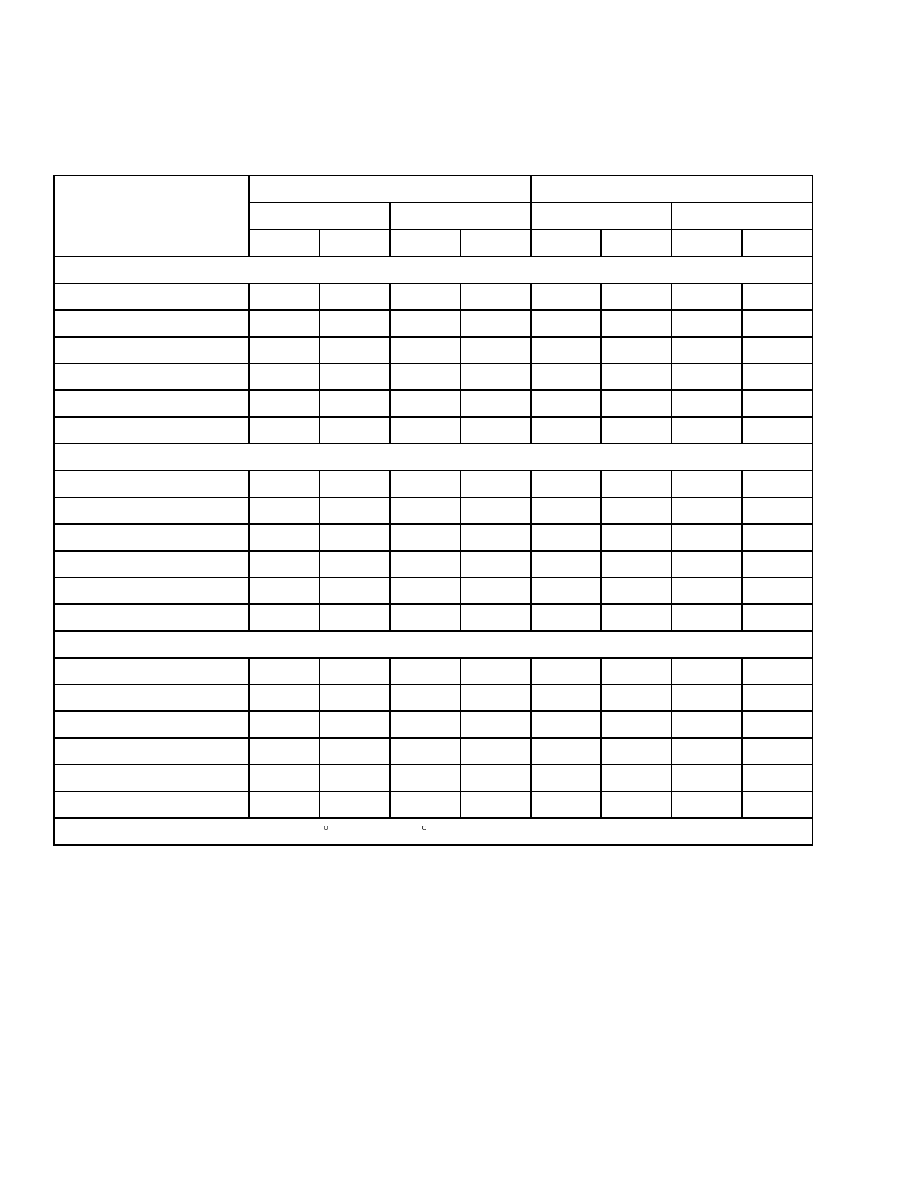
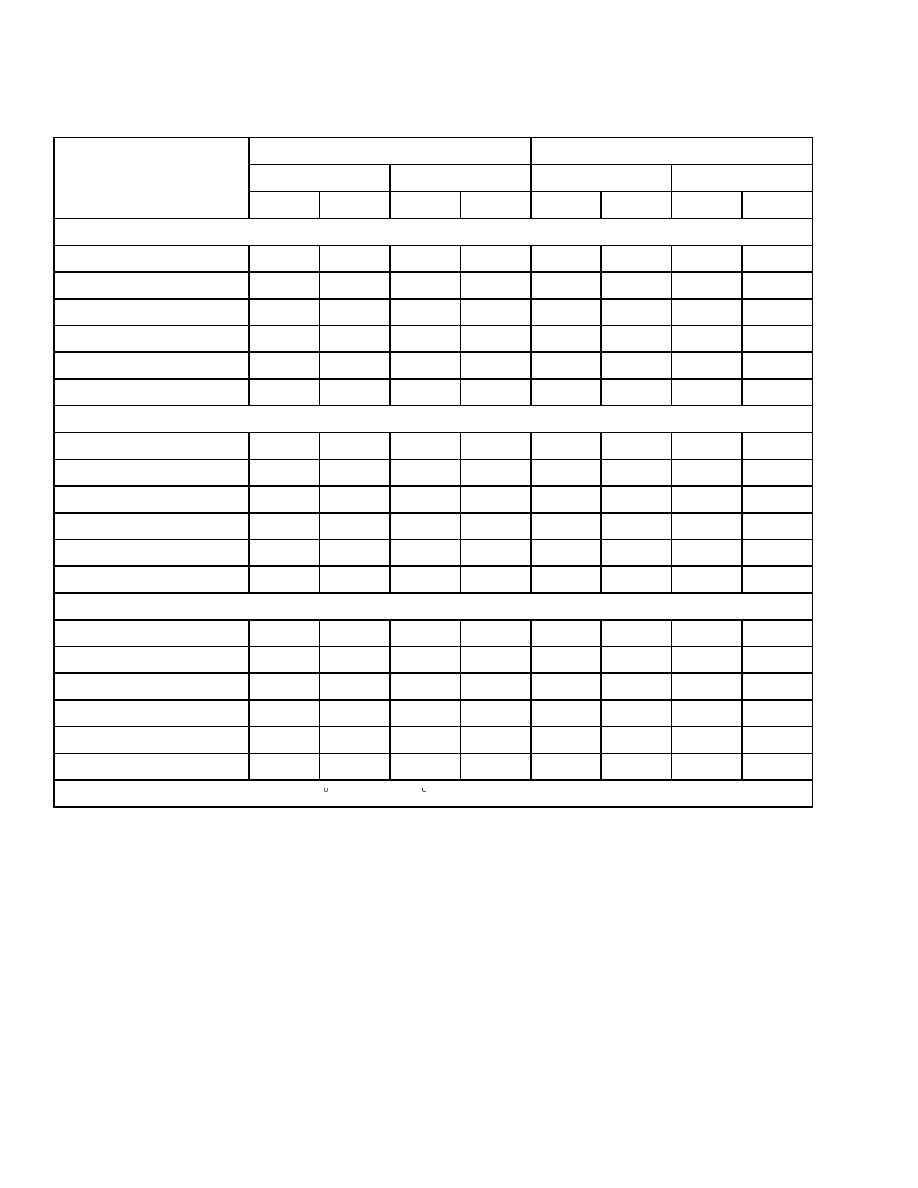
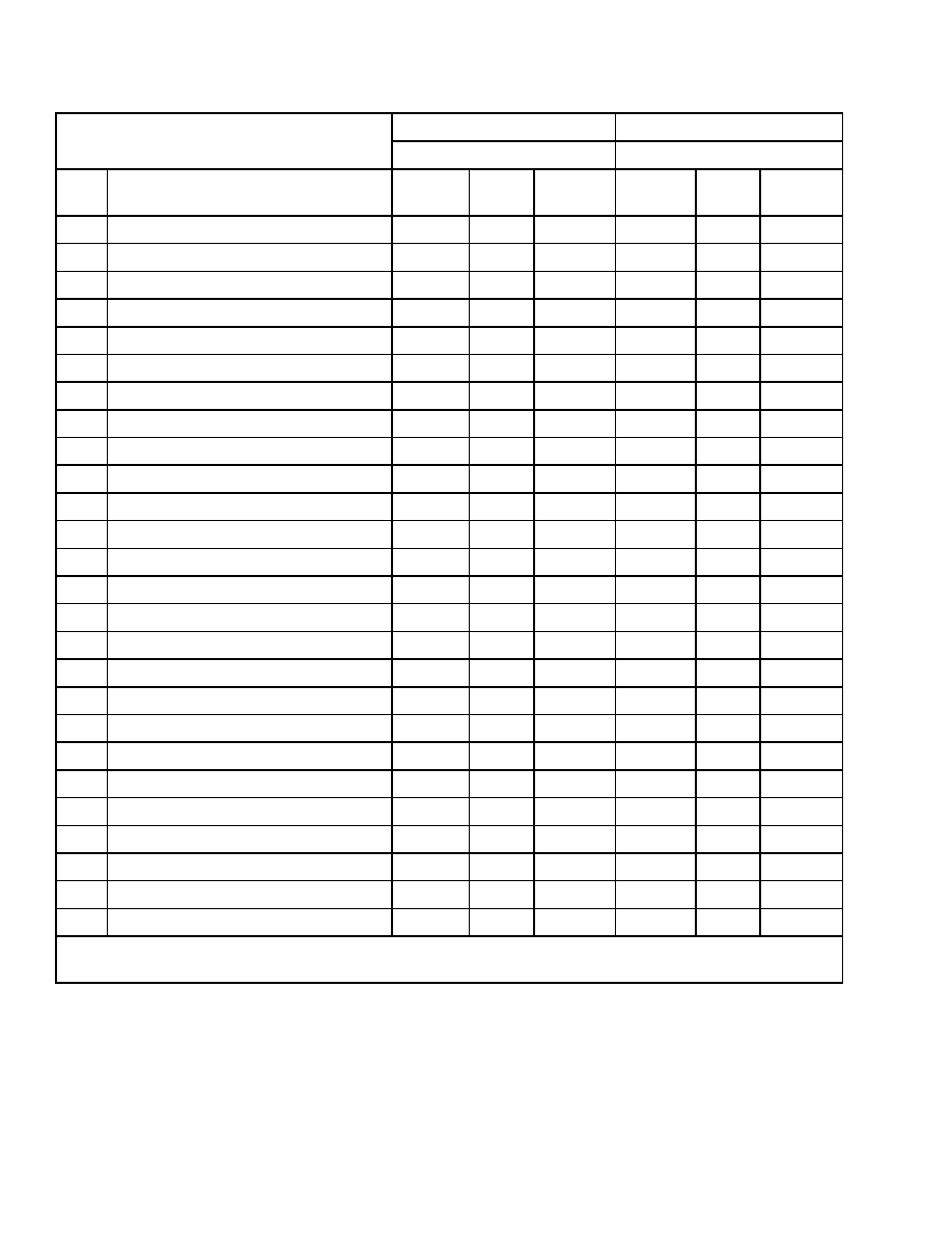
Mast Speeds
19CC PUMP ONE- AND TWO-SPEED CONTACTOR
Lifting*
Lowering*
No Load
Rated Load
No Load
Rated Load
Model
m/sec
ft/min
m/sec
ft/min
m/sec
ft/min
m/sec
ft/min
Two-Stage Limited Free-Lift Mast
J1.60MT
2
/36V
0.48
95
0.33
65
0.47
93
0.51
100
J1.80XMT
2
/36V
0.48
95
0.30
59
0.47
93
0.51
100
J2.00XMT
2
/36V
0.48
95
0.28
55
0.47
93
0.51
100
J1.60XMT
2
/48V
0.58
114
0.30
59
0.47
93
0.51
100
J1.80XMT
2
/48V
0.58
114
0.28
55
0.47
93
0.51
100
J2.00XMT
2
/48V
0.58
114
0.25
49
0.47
93
0.51
100
Two-Stage Full Free-Lift Mast
J1.60XMT
2
/36V
0.46
91
0.30
59
0.37
73
0.47
93
J1.80XMT
2
/36V
0.46
91
0.28
55
0.37
73
0.47
93
J2.00MT
2
/36V
0.46
91
0.25
49
0.37
73
0.47
93
J1.60XMT
2
/48V
0.56
110
0.38
75
0.37
73
0.47
93
J1.80XMT
2
/48V
0.56
110
0.36
71
0.37
73
0.47
93
J2.00XMT
2
/48V
0.56
110
0.33
65
0.37
73
0.47
93
Three-Stage Full Free-Lift Mast
J1.60XMT
2
/36V
0.46
91
0.30
59
0.41
81
0.48
94
J1.80XMT
2
/36V
0.46
91
0.28
55
0.41
81
0.48
94
J2.00XMT
2
/36V
0.46
91
0.25
49
0.41
81
0.48
94
J1.60XMT
2
/48V
0.56
110
0.38
75
0.41
81
0.48
94
J1.80XMT
2
/48V
0.56
110
0.36
71
0.41
81
0.48
94
J2.00XMT
2
/48V
0.56
110
0.33
65
0.41
81
0.48
94
* Hydraulic Oil Temperature 62 to 73 C (144 to 163 F)
2
8000 SRM 586
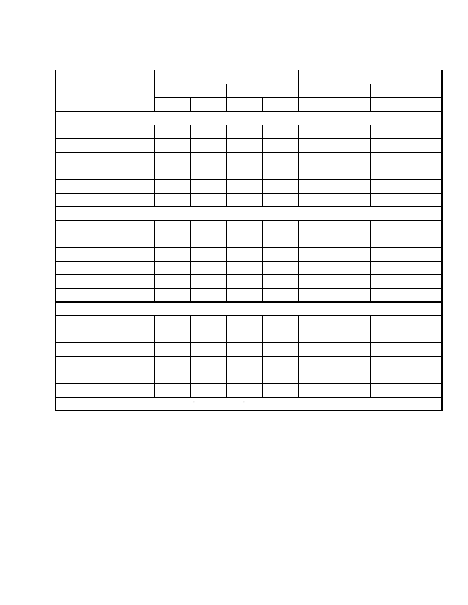
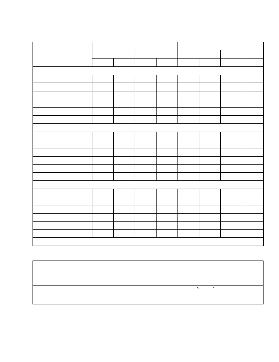
Mast Speeds
19CC PUMP TRANSISTOR CONTROL
Lifting*
Lowering*
No Load
Rated Load
No Load
Rated Load
Model
m/sec
ft/min
m/sec
ft/min
m/sec
ft/min
m/sec
ft/min
Two-Stage Limited Free-Lift Mast
J1.60MT
2
/36V
0.47
93
0.30
59
0.47
93
0.51
100
J1.80XMT
2
/36V
0.47
93
0.28
55
0.47
93
0.51
100
J2.00XMT
2
/36V
0.47
93
0.26
51
0.47
93
0.51
100
J1.60XMT
2
/48V
0.53
104
0.39
77
0.47
93
0.51
100
J1.80XMT
2
/48V
0.53
104
0.37
73
0.47
93
0.51
100
J2.00XMT
2
/48V
0.53
104
0.34
67
0.47
93
0.51
100
Two-Stage Full Free-Lift Mast
J1.60XMT
2
/36V
0.44
87
0.26
51
0.37
73
0.47
93
J1.80XMT
2
/36V
0.44
87
0.26
51
0.37
73
0.47
93
J2.00MT
2
/36V
0.44
87
0.24
47
0.37
73
0.47
93
J1.60XMT
2
/48V
0.51
100
0.37
73
0.37
73
0.47
93
J1.80XMT
2
/48V
0.51
100
0.34
67
0.37
73
0.47
93
J2.00XMT
2
/48V
0.51
100
0.32
63
0.37
73
0.47
93
Three-Stage Full Free-Lift Mast
J1.60XMT
2
/36V
0.44
87
0.27
53
0.41
81
0.48
94
J1.80XMT
2
/36V
0.44
87
0.26
51
0.41
81
0.48
94
J2.00XMT
2
/36V
0.44
87
0.24
47
0.41
81
0.48
94
J1.60XMT
2
/48V
0.51
100
0.37
73
0.41
81
0.48
94
J1.80XMT
2
/48V
0.51
100
0.34
67
0.41
81
0.48
94
J2.00XMT
2
/48V
0.51
100
0.31
61
0.41
81
0.48
94
* Hydraulic Oil Temperature 62 to 73 C (144 to 163 F)
3
Mast Speeds
8000 SRM 586
12CC PUMP ONE- AND TWO-SPEED CONTACTOR
Lifting*
Lowering*
No Load
Rated Load
No Load
Rated Load
Model
m/sec
ft/min
m/sec
ft/min
m/sec
ft/min
m/sec
ft/min
Two-Stage Limited Free-Lift Mast
J1.60MT
2
/36V
0.40
79
0.23
45
0.47
93
0.51
100
J1.80XMT
2
/36V
0.40
79
0.22
43
0.47
93
0.51
100
J2.00XMT
2
/36V
0.40
79
0.21
41
0.47
93
0.51
100
J1.60XMT
2
/48V
0.50
98
0.33
65
0.47
93
0.51
100
J1.80XMT
2
/48V
0.50
98
0.31
61
0.47
93
0.51
100
J2.00XMT
2
/48V
0.50
98
0.29
57
0.47
93
0.51
100
Two-Stage Full Free-Lift Mast
J1.60XMT
2
/36V
0.39
77
0.23
45
0.37
73
0.47
93
J1.80XMT
2
/36V
0.39
77
0.22
43
0.37
73
0.47
93
J2.00MT
2
/36V
0.39
77
0.21
41
0.37
73
0.47
93
J1.60XMT
2
/48V
0.49
96
0.33
65
0.37
73
0.47
93
J1.80XMT
2
/48V
0.49
96
0.31
61
0.37
73
0.47
93
J2.00XMT
2
/48V
0.49
96
0.29
57
0.37
73
0.47
93
Three-Stage Full Free-Lift Mast
J1.60XMT
2
/36V
0.37
73
0.22
43
0.41
81
0.48
94
J1.80XMT
2
/36V
0.37
73
0.21
41
0.41
81
0.48
94
J2.00XMT
2
/36V
0.37
73
0.20
39
0.41
81
0.48
94
J1.60XMT
2
/48V
0.47
93
0.32
63
0.41
81
0.48
94
J1.80XMT
2
/48V
0.47
93
0.30
59
0.41
81
0.48
94
J2.00XMT
2
/48V
0.47
93
0.28
55
0.41
81
0.48
94
* Hydraulic Oil Temperature 62 to 73 C (144 to 163 F)
4
8000 SRM 586
Mast Speeds
12CC PUMP TRANSISTOR CONTROL
Lifting*
Lowering*
No Load
Rated Load
No Load
Rated Load
Model
m/sec
ft/min
m/sec
ft/min
m/sec
ft/min
m/sec
ft/min
Two-Stage Limited Free-Lift Mast
J1.60MT
2
/36V
0.38
75
0.21
41
0.47
93
0.51
100
J1.80XMT
2
/36V
0.38
75
0.21
41
0.47
93
0.51
100
J2.00XMT
2
/36V
0.38
75
0.20
39
0.47
93
0.51
100
J1.60XMT
2
/48V
0.45
89
0.33
65
0.47
93
0.51
100
J1.80XMT
2
/48V
0.45
89
0.31
61
0.47
93
0.51
100
J2.00XMT
2
/48V
0.45
89
0.29
57
0.47
93
0.51
100
Two-Stage Full Free-Lift Mast
J1.60XMT
2
/36V
0.37
73
0.21
41
0.37
73
0.47
93
J1.80XMT
2
/36V
0.37
73
0.21
41
0.37
73
0.47
93
J2.00MT
2
/36V
0.37
73
0.20
39
0.37
73
0.47
93
J1.60XMT
2
/48V
0.44
87
0.33
65
0.37
73
0.47
93
J1.80XMT
2
/48V
0.44
87
0.31
61
0.37
73
0.47
93
J2.00XMT
2
/48V
0.44
87
0.29
57
0.37
73
0.47
93
Three-Stage Full Free-Lift Mast
J1.60XMT
2
/36V
0.35
69
0.21
41
0.41
81
0.48
94
J1.80XMT
2
/36V
0.35
69
0.21
41
0.41
81
0.48
94
J2.00XMT
2
/36V
0.35
69
0.20
39
0.41
81
0.48
94
J1.60XMT
2
/48V
0.43
85
0.32
63
0.41
81
0.48
94
J1.80XMT
2
/48V
0.43
85
0.30
59
0.41
81
0.48
94
J2.00XMT
2
/48V
0.43
85
0.28
55
0.41
81
0.48
94
* Hydraulic Oil Temperature 62 to 73 C (144 to 163 F)
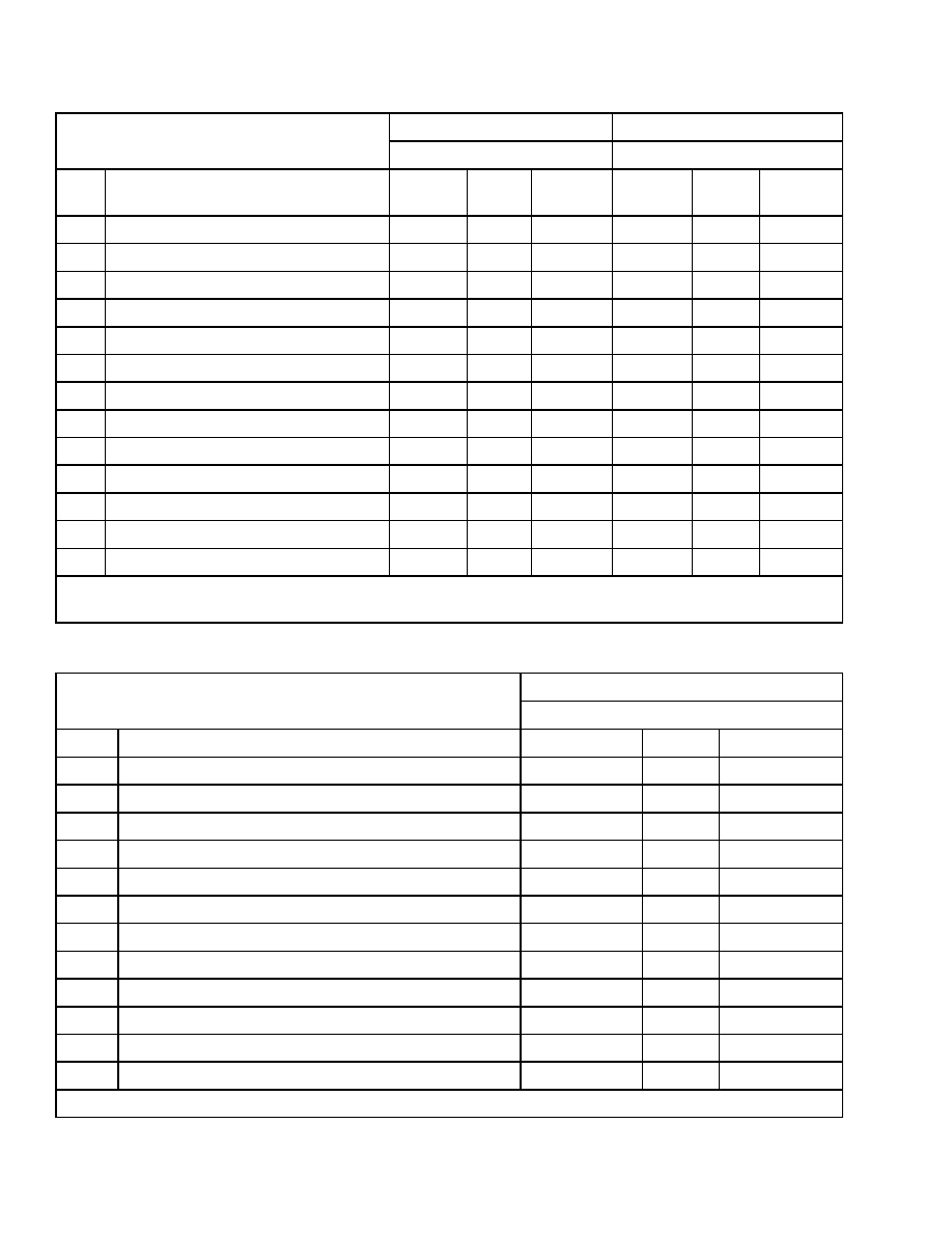
MAST/TILT DRIFT SPEEDS
Lift/Tilt
Drift Speeds
LIFT at Carriage
* 12.7 mm (0.5 in.) in 1 minute
TILT at Carriage
*0.5 Degree in 1 minute
*With hydraulic oil at normal operating temperature 50 C (122 F).
Start measurement with mast at vertical position and the rated load raised to 2.5 m (8.2 ft).
Use maximum lift height if the maximum is less than 2.5 m (8.2 ft).
5
Torque Specifications
8000 SRM 586
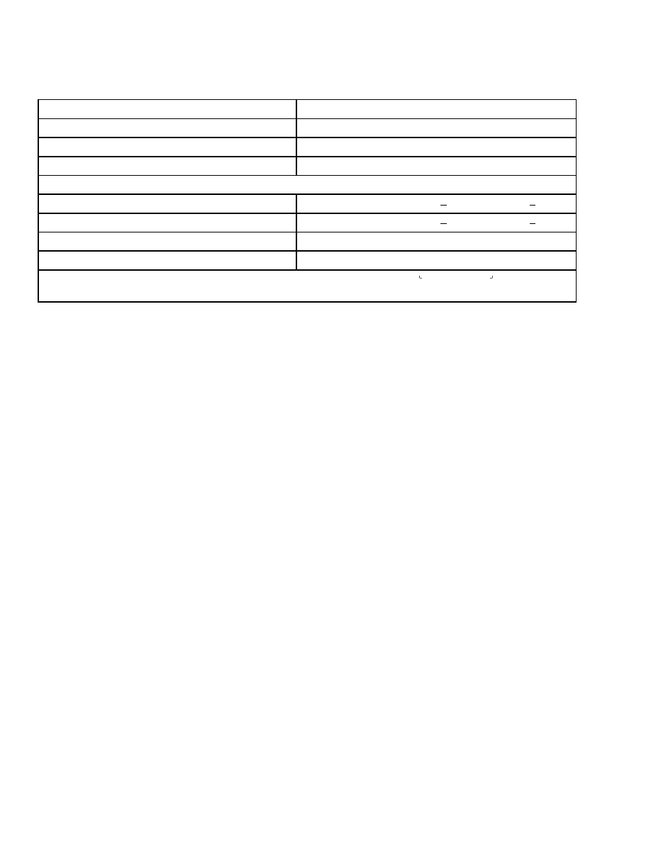
Hydraulic System
Item
Specification
Hydraulic Tank (To Full Mark)
17.0 liter (4.50 gal)
Hydraulic Tank Capacity
18.0 liter (4.75 gal)
Hydraulic System Capacity#
23.0 liter (6 gal)
Relief Pressures*
Lift System
17.92 MPa (2600 psi) +0.69 0.35 MPa (+100 50 psi)
Tilt System
17.92 MPa (2600 psi) +0.69 0.35 MPa (+100 50 psi)
Auxiliary System
13.8 MPa (2000 psi) ±0.70 MPa (100 psi)
Steering System
7.7 MPa (1200 psi) ±0.35 MPa (50 psi)
*With hydraulic oil at normal operating temperature 65 to 77 C (149 to 171 F)
#Check with all cylinders and hoses full at static condition.
Torque Specifications
FRAME
Hexagon Head Bolts - Counterweight
435 N•m (321 lbf ft)
Screws - Overhead Guard
134 N•m (99 lbf ft)
TRANSAXLE
Hexagon Head Bolts - Frame to Transaxle
(Apply Sealant HCE-66 to the Threads)
256 N•m (189 lbf ft)
Hexagon Head Bolts - Motor to Transaxle
41 to 49 N•m (30 to 36 lbf ft)
Pinion Nut
88 N•m (65 lbf ft)
Screws - Housing Cover 10 mm
41 N•m (30 lbf ft)
Screws - Housing Cover Cap 6 mm
3 N•m (2 lbf ft)
Nuts - Service Brake Mounting (Caliper
Must Move Freely)
19 N•m (14 lbf ft)
Nuts - Parking Brake Mounting
31 to 41 N•m (23 to 30 lbf ft)
Nut - Drive Shaft (Lubricated) (Rotating
Torque) See 1300 SRM 568.
Nut - Bevel Pinion Shaft (Housing End)
See 1300 SRM 568.
Nut - Bevel Pinion Shaft (Brake Caliper
End) See 1300 SRM 568.
Wheel Studs (Apply Sealant HCE-66
to the Threads)
30 to 50 N•m (22 to 37 lbf ft)
BRAKE SYSTEM
Service and Parking Brake Brackets to
Transaxle Housing (5)
41 N•m (30 lbf ft)
Service Brake Assembly See 1800 SRM 570.
Parking Brake Assembly See 1800 SRM 570.
WHEELS
Steer Wheel Lug Nuts
140 N•m (103 lbf ft)
Drive Wheel Lug Nuts
170 N•m (125 lbf ft)
Drain, Fill, and Level Plugs
22 N•m (16 lbf ft)
6

8000 SRM 586
Accelerator Potentiometer Checks
STEERING SYSTEM
Steering Wheel Retaining Nut
41 to 54 N•m (30 to 40 lbf ft)
Hexagon Head Bolts - Rotary Actu-
ator to Frame
63 N•m (46 lbf ft)
Hexagon Head Bolts - Power Steer-
ing Pump Body
34 to 40 N•m (25 to 30 lbf ft)
Hexagon Head Bolts - Hydraulic
Steering Motor
5 to 8 N•m (4 to 6 lbf ft)
Hexagon Head Bolts - Flange Cover (6) 30
to 36 N•m (22 to 27 lbf ft)
Hexagon Head Bolts - End Cover (6) 30 to
36 N•m (22 to 27 lbf ft)
Hexagon Head Bolts - Steering Control Unit to
Steering Column 19 N•m (14 lbf ft)
Hexagon Head Bolt - Gear Housing
84 N•m (62 lbf ft)
Hydraulic Fittings - Steering Pump
24.9 to 29.4 N•m (18 to 22 lbf ft)
HYDRAULIC SYSTEM
Nuts - Studs on Main Control Valve (3)
21 N•m (15 lbf ft)
Hexagon Head Bolts - Case of Hy-
draulic Pump (4)
50 to 60 N•m (37 to 44 lbf ft)
Relief Valves (Main and Secondary)
20 N•m (15 lbf ft)
Hydraulic Fittings
24.9 to 29.4 N•m (18 to 22 lbf ft)
MAST/TILT/ATTACHMENT SYSTEMS
Hexagon Head Bolts - Mast Mounts, Cowl
51 N•m (38 lbf ft)
Hexagon Head Bolt and Nut - Rod
End of Tilt Cylinder
90 N•m (66 lbf ft)
Nut Side - Shift Cylinder Piston (Internal)
122 to 135 N•m (90 to 100 lbf ft)
Hexagon Head Bolts - Sideshift Cylin-
der Mounting
320 N•m (236 lbf ft)
Hexagon Head Bolts - Caps to Transaxle
90 N•m (66 lbf ft)
Hexagon Head Bolts - Tilt Cylinder Rod
End Pin Retaining
90 N•m (66 lbf ft)
Hexagon Head Bolts - Carriage Apron
Section Assembly
435 N•m (321 lbf ft)
Nuts - Sideshift Cylinder Mounting
26 N•m (19 lbf ft)
Accelerator Potentiometer Checks
Accelerator Potentiometer
Check the voltage between wire 29 and wire 13 battery negative. Check with the parking brake ON, the
key switch ON, and the connector to the MONOTROL
®
disconnected. When checking a lift truck with a
directional control lever, keep the lever in NEUTRAL.
1. Forward or reverse contactor picks up 3.4 to 3.57 volts.
2. End of pedal travel less than 0.6 volt.
3. Check for battery voltage at TB2 on the SCR controller. (If battery voltage is not obtained, the MS 1
switch in the accelerator is defective, and the accelerator must be replaced.)
Resistance
Resistance between the bare metal frame and any part of the electrical circuit must not be less than
50,000 ohms.
7
Adjustments
8000 SRM 586
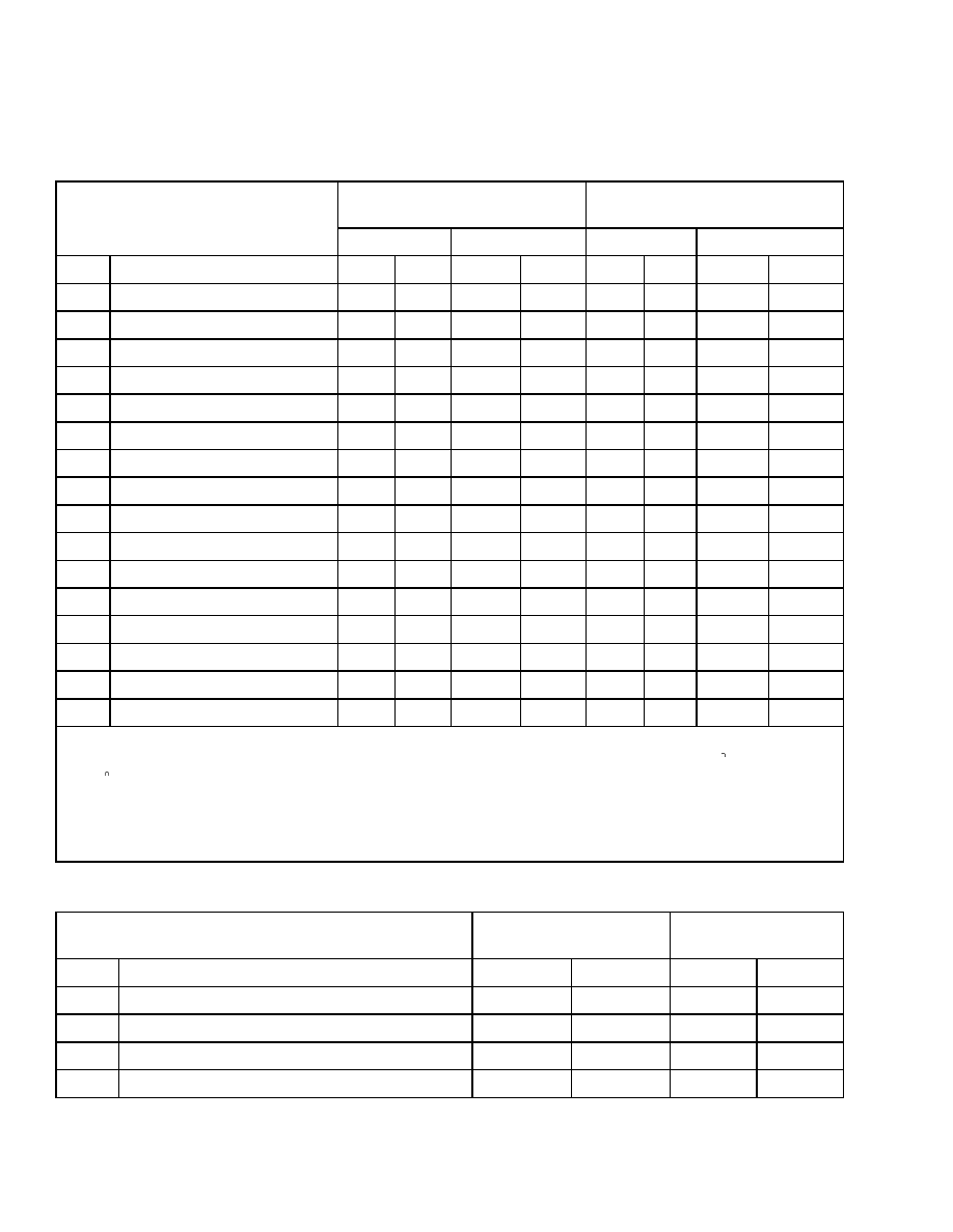
Adjustments
EV 100 LX TRACTION CARD
Performance Standard
Setting
Energy Saver Setting
Function
J1.60XMT
J1.80-2.00XMT
J1.60XMT
J1.80-2.00XMT
No.
Description
36V
48V
36V
48V
36V
48V
36V
48V
1
Stored Fault Code
0
0
0
0
0
0
0
0
2
Creep Speed
100
100
100
100
100
100
100
100
3
Control Accel. & 1A
15
15
15
15
25
25
25
25
4
Current Limit
220
220
220
220
220
220
220
220
5
Plugging Distance
130
160
130
160
-
115
-
115
6
1A Dropout Current
90
90
90
90
90
90
90
90
7
W/O Field Weakening-PU
0
0
0
0
0
0
0
0
8
W/O Field Weakening-PU
0
0
0
0
0
0
0
0
11
Speed Limit 1
115
130
115
130
115
115
115
115
12
Speed Limit 2
130
145
125
140
130
130
130
130
13
Speed Limit 3
0
0
0
0
0
0
0
0
14
Internal Res. Comp.
17
17
17
17
17
17
17
17
15
Battery Volts
200
200
200
200
200
200
200
200
16
Pedal Position Plug
32
32
32
32
32
32
32
32
17
Card Type Select
2
2
2
2
2
2
2
2
18
Steer Pump Time Delay
17
17
17
17
17
17
17
17
NOTE:
1. Power to the inside traction motor should cut out when the steer tire turns more than 35 and reverses at
85 from the straight-ahead position.
2. Truck must start on 10% ramp with rated load after 0.3 m (12 in.) rollback.
3. All card settings are ±2.
NOTE:
All card functions not listed in the chart are to be set to zero (0).
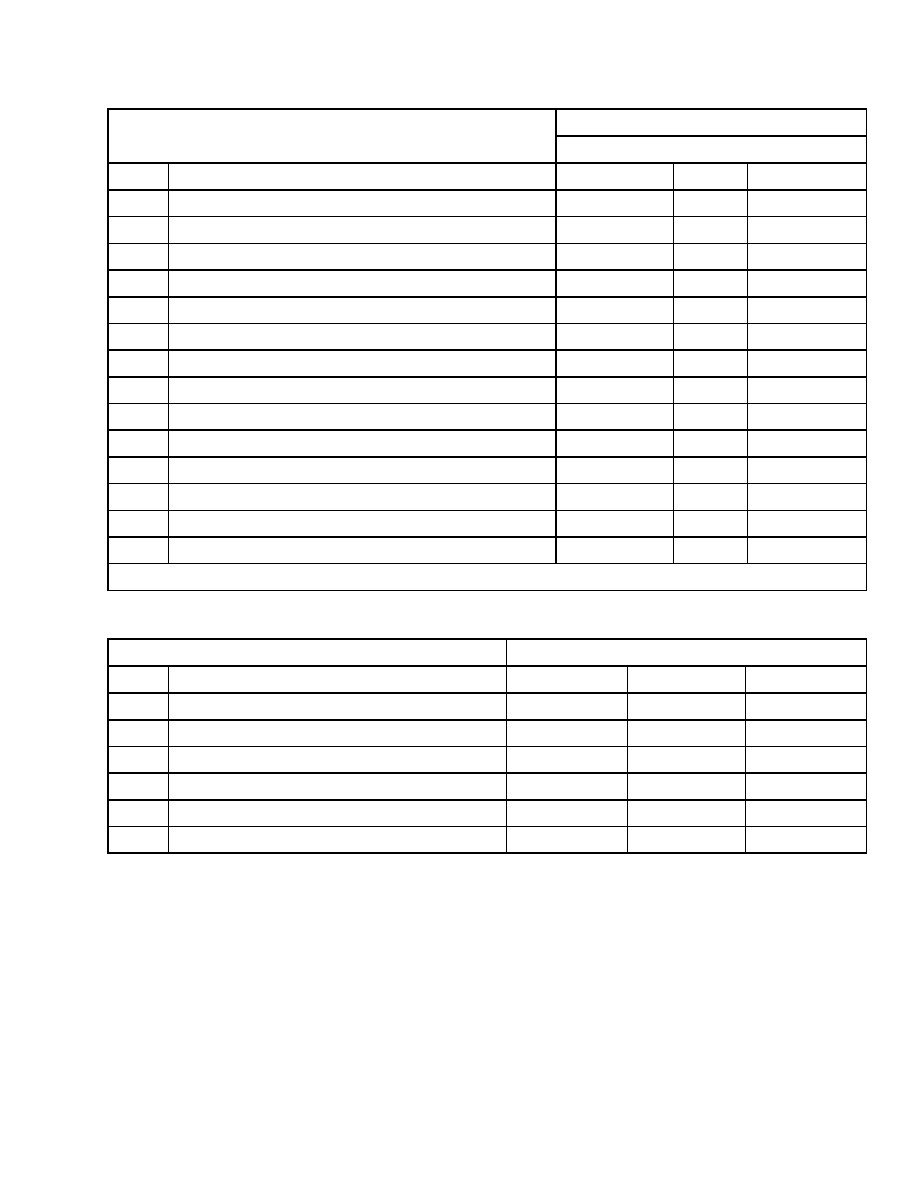
EV 100 LX PUMP CARD
Function
Performance
Standard Setting
Energy Saver
Setting
No.
Description
36V
48V
36V
48V
1
Status
0
0
0
0
2
Internal Resistance Compensation
64
64
64
64
3
Controlled Acceleration & 1A
26
26
40
40
4
Current Limit
255
255
255
255
8
8000 SRM 586
Controller Settings
Function
Performance
Standard Setting
Energy Saver
Setting
No.
Description
36V
48V
36V
48V
11
Speed Limit 1 Slow Lift
65
65
65
65
12
Speed Limit 2 Tilt Speed
40
40
30
30
13
Speed Limit 3 Auxiliary
65
65
65
65
14
Speed Limit 4 Hi-Speed Lift
255
255
255
255
16
Internal Resistance Compensation
25
25
25
25
17
Card Type Selection
30
30
30
30
All card settings are ±2.
NOTE:
All card functions not listed in the chart are to be set to zero (0).
Controller Settings
SR/SP TRACTION CONTROLLER SETTINGS - STANDARD WITH AUTO REGEN
36 Volts
48 Volts
Function
Setting
Setting
No.
Description
Mini-
mum
Card
Maxi-
mum
Mini-
mum
Card
Maxi-
mum
1
Auto Regen Cancel Speed
0
18
50
17
18
50
2
Creep Speed
0
15
255
0
15
255
3
Controlled Acceleration
40
81
255
40
121
255
4
Armature Current Limit
0
255
255
0
255
255
5
Plugging Current Limit
0
100
105
0
100
105
6
FW Ratio
22
25
28
42
45
48
7
Minimum Field Current
0
55
80
0
51
80
8
Maximum Field Current
198
200
202
198
200
202
9
Regen Braking Current Limit
0
110
115
0
110
115
10
Regen Field Current
152
155
158
152
155
158
11
Turn Speed Limit
51
130
180
51
130
180
12
Maximum Armature % On
0
0
130
0
66
130
13
Speed Limit 3
51
130
180
51
130
180
14
Internal Resistance Compensation
0
21
255
0
13
255
Battery Volts - Left Controller (Master)
184
186
250
184
186
250
15
Battery Volts - Right Controller (Slave)
251
255
255
251
255
255
NOTE:
Left and right controller functions must be programmed to identical values except for Function 15 and
Function 17.
9
Controller Settings
8000 SRM 586
36 Volts
48 Volts
Function
Setting
Setting
No.
Description
Mini-
mum
Card
Maxi-
mum
Mini-
mum
Card
Maxi-
mum
16
Stall Trip Point % On
100
105
110
100
105
110
18
Steer Pump Time Delay
0
25
255
0
25
255
19
Maintenance Code Hourmeter (×1)
0
255
255
0
255
255
20
Maintenance Code Hourmeter (×100)
0
255
255
0
255
255
21
Auto Decel Current Limit
51
60
255
51
60
255
22
Mode
184
184
184
184
184
184
23
Special Customer Function
6
6
6
6
6
6
24
FW Start
72
73
76
44
45
50
24
Monitor
0
0
0
0
0
0
26
Base Ratio
63
65
68
63
65
68
48
Mode 1 - Controlled Acceleration
40
141
255
40
141
255
49
Mode 1 - FW Start
56
57
60
44
45
50
50
Mode 1- FW Ratio
32
35
38
42
45
48
51
Mode 1 - Maximum Armature % On
65
101
130
65
101
130
52
Mode 2 - Controlled Acceleration
40
121
255
40
121
255
53
Mode 2 - FW Start
56
57
60
44
45
50
54
Mode 2 - FW Ratio
32
35
38
42
45
48
55
Mode 2 - Maximum Armature % On
65
90
130
65
90
130
56
Mode 3 - Controlled Acceleration
40
101
255
40
121
255
57
Mode 3 - FW Start
56
57
60
44
45
50
58
Mode 3 - FW Ratio
32
35
38
42
45
48
59
Mode 3 - Maximum Armature % On
65
79
130
65
79
130
60
Mode 4 - Controlled Acceleration
40
81
255
40
121
255
61
Mode 4 - FW Start
72
73
78
44
45
50
62
Mode 4 - FW Ratio
22
25
28
42
45
48
63
Mode 4 - Maximum Armature % On
0
0
130
0
66
130
NOTE:
Left and right controller functions must be programmed to identical values except for Function 15 and
Function 17.
10

8000 SRM 586
Controller Settings
SR/SP TRACTION CONTROLLER SETTINGS - STANDARD WITHOUT AUTO DECEL
36 Volts
48 Volts
Function
Setting
Setting
No.
Description
Mini-
mum
Card
Maxi-
mum
Mini-
mum
Card
Maxi-
mum
1
Auto Regen Cancel Speed
0
18
50
17
18
50
2
Creep Speed
0
15
255
0
15
255
3
Controlled Acceleration
40
81
255
40
121
255
4
Armature Current Limit
0
255
255
0
255
255
5
Plugging Current Limit
0
100
105
0
100
105
6
FW Ratio
22
25
28
42
45
48
7
Minimum Field Current
0
55
80
0
51
80
8
Maximum Field Current
198
200
202
198
200
202
9
Regen Braking Current Limit
0
110
115
0
110
115
10
Regen Field Current
152
155
158
152
155
158
11
Turn Speed Limit
51
130
180
51
130
180
12
Maximum Armature % On
0
0
130
0
66
130
13
Speed Limit 3
51
130
180
51
130
180
14
Internal Resistance Compensation
0
21
255
0
13
255
Battery Volts - Left Controller (Master)
184
186
250
184
186
250
15
Battery Volts - Right Controller (Slave)
251
255
255
251
255
255
16
Stall Trip Point % On
100
105
110
100
105
110
18
Steer Pump Time Delay
0
25
255
0
25
255
19
Maintenance Code Hourmeter (×1)
0
255
255
0
255
255
20
Maintenance Code Hourmeter (×100)
0
255
255
0
255
255
21
Auto Decel Braking Current Limit
51
60
255
51
255
255
22
Mode
184
184
184
184
184
184
23
Special Customer Function
6
6
6
6
6
6
24
FW Start
72
73
76
44
45
50
25
Monitor
0
0
0
0
0
0
26
Base Ratio
63
65
68
63
65
68
48
Mode 1 - Controlled Acceleration
40
141
255
10
141
255
49
Mode 1 - FW Start
56
57
60
44
45
50
50
Mode 1 - FW Ratio
32
35
38
42
45
48
NOTE:
Left and right controller functions must be programmed to identical values except for Function 15 and
Function 17.
11
Controller Settings
8000 SRM 586
36 Volts
48 Volts
Function
Setting
Setting
No.
Description
Mini-
mum
Card
Maxi-
mum
Mini-
mum
Card
Maxi-
mum
51
Mode 1 - Maximum Armature % On
65
101
130
65
101
130
52
Mode 2 - Controlled Acceleration
40
121
255
40
121
255
53
Mode 2 - FW Start
56
57
60
44
45
50
54
Mode 2- FW Ratio
32
35
38
42
45
48
55
Mode 2 - Maximum Armature % On
65
90
130
65
90
130
56
Mode 3 - Controlled Acceleration
40
101
255
40
121
255
57
Mode 3 - FW Start
56
57
60
44
45
50
58
Mode 3 - FW Ratio
32
35
38
42
45
48
59
Mode 3 - Maximum Armature % On
65
79
130
65
79
130
60
Mode 4 - Controlled Acceleration
40
81
255
40
121
255
61
Mode 4 - FW Start
72
73
78
44
45
50
62
Mode 4 - FW Ratio
22
25
28
42
45
48
63
Mode 4 - Maximum Armature % On
0
0
130
0
66
130
NOTE:
Left and right controller functions must be programmed to identical values except for Function 15 and
Function 17.
SR/SP LIFT PUMP CONTROLLER SETTINGS
36 and 48 Volts
Function
Setting
No.
Description
Minimum
Card
Maximum
1
Stored Fault Code
1
0
0
255
2
Internal Resistance Compensation Start
0
64
255
3
Controlled Acceleration
10
26
150
4
Current Limit
0
255
255
7
Internal Resistance Compensation Rate
0
15
255
11
Speed Limit 1 - Tilt, Auxiliary 1
30
50
70
12
Speed Limit 2 - Slow Lift, Auxiliary 2
30
65
70
13
Speed Limit 3 - Fast Lift
30
255
255
14
Speed Limit 4 (NOT USED)
0
0
0
16
Internal Resistance Compensation
0
25
255
17
Card Type
63
65
71
22
Mode
184
184
184
1
Any number other than zero (0) can be read as a possible fault.
12
8000 SRM 586
Controller Settings
36 and 48 Volts
Function
Setting
No.
Description
Minimum
Card
Maximum
25
Computer Monitor Off
0
0
0
26
Computer Signal Monitor Off
0
0
0
48
Mode 1 - Controlled Acceleration
25
55
150
49
Mode 1 - Speed Limit 2 - Slow Lift, Auxiliary 2
30
65
70
50
Mode 1 - Speed Limit 3 - Fast Lift
30
84
255
52
Mode 2 - Controlled Acceleration
25
45
150
53
Mode 2 - Speed Limit 2 - Slow Lift, Auxiliary 2
30
65
70
54
Mode 2 - Speed Limit 3 - Fast Lift
30
96
255
56
Mode 3 - Controlled Acceleration
25
35
150
57
Mode 3 - Speed Limit 2 - Slow Lift, Auxiliary 2
30
65
70
58
Mode 3 - Speed Limit 3 - Fast Lift
30
108
255
60
Mode 4 - Controlled Acceleration
25
26
150
61
Mode 4 - Speed Limit 2 - Slow Lift, Auxiliary 2
30
65
70
62
Mode 4 - Speed Limit 3 - Fast Lift
30
255
255
1
Any number other than zero (0) can be read as a possible fault.
SR/SP TRACTION CONTROLLER SETTINGS - 36V ENERGY OPTION
Function
Setting
No.
Description
Minimum
Factory
Maximum
3
Controlled Acceleration
40
121
255
6
FW Ratio
32
35
38
24
FW Start
56
57
60
60
Mode 4 - Controlled Acceleration
40
121
255
61
Mode 4 - FW Ratio
56
57
60
62
Mode 4 - FW Start
32
35
38
13
Battery Size Specifications
8000 SRM 586
Battery Size Specifications
TYPE: LEAD ACID BATTERY
Maximum Battery
Compartment Size
1
Maximum Battery Size
Battery
Weight
Battery
Spacers
Width
Length
Height
Voltage
Width
Length
Height
2
Range
Division
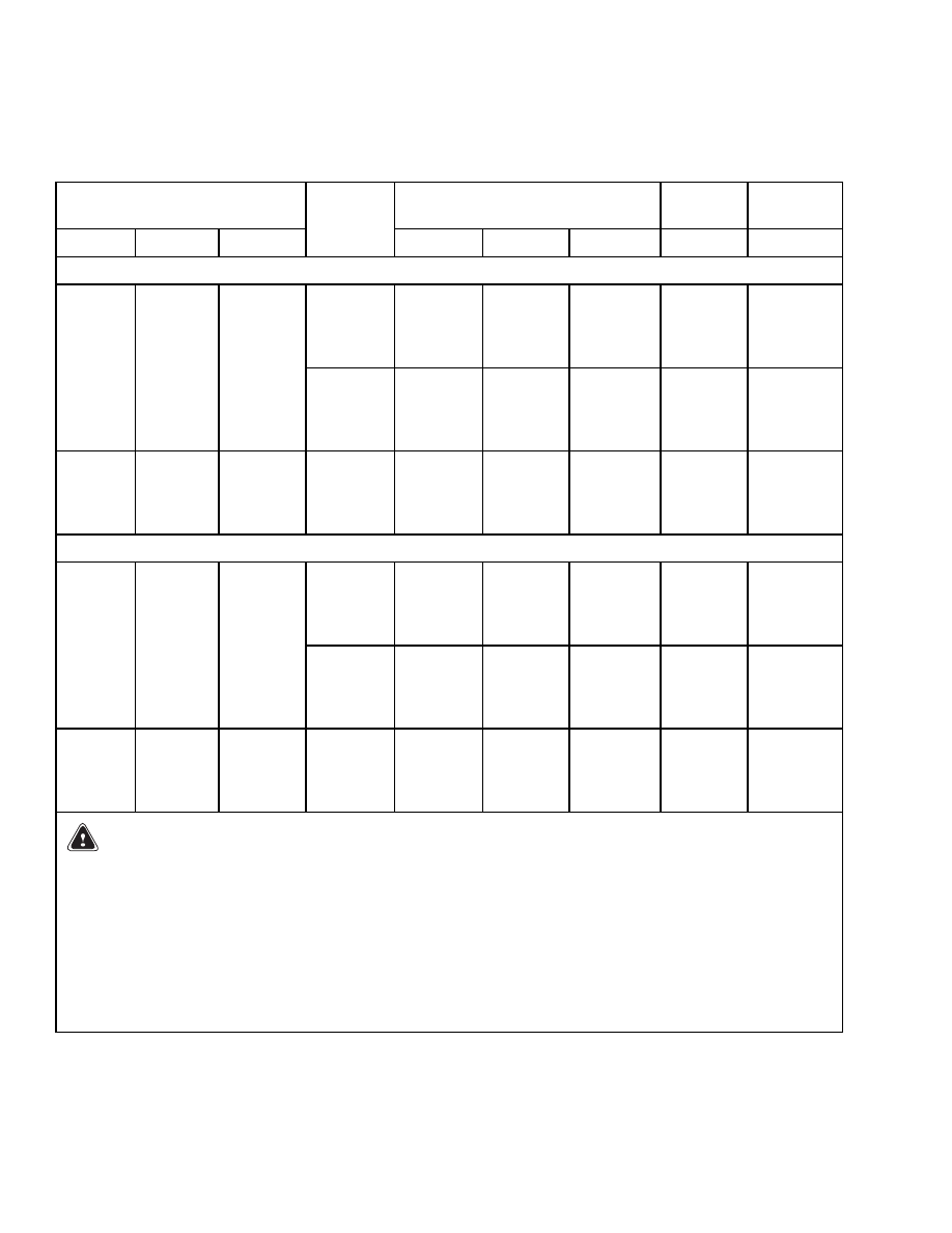
J.160XMT TRUCK CAPACITY 1600 kg (3527 lb) - WHEEL BASE 1385 mm (54.5 in.)
48/BS
980 mm
(38.6 in.)
537 mm
(21.1 in.)
655 mm
(25.8 in.)
855 to
975 kg
(1885 to
2150 lb)
2031110
990 mm
(39.0 in.)
611 mm
(24.1 in.)
676 mm
(26.6 in.)
36/BS
980 mm
(38.6 in.)
537 mm
(21.1 in.)
655 mm
(25.8 in.)
855 to
975 kg
(1885 to
2150 lb)
2031110
839 mm
(33.0 in.)
639 mm
(25.2 in.)
650 mm
(25.6 in.)
48/DIN
830 mm
(32.7 in.)
630 mm
(24.8 in.)
612 mm
(24.1 in.)
810 to
896 kg
(1786 to
1975 lb)
2031111
J1.80XMT TRUCK CAPACITY 1800 kg (3968 lb) - WHEEL BASE 1495 mm (58.9 in.)
48/BS
980 mm
(38.6 in.)
632 mm
(24.9 in.)
655 mm
(25.8 in.)
1040 to
1110 kg
(2293 to
2447 lb)
2014631
990 mm
(39.0 in.)
721 mm
(28.4 in.)
676 mm
(26.6 in.)
36/BS
980 mm
(38.6 in.)
632 mm
(24.9 in.)
655 mm
(25.8 in.)
1040 to
1110 kg
(2293 to
2447 lb)
2014631
839 mm
(33.0 in.)
749 mm
(29.5 in.)
650 mm
(25.6 in.)
48/DIN
830 mm
(32.7 in.)
738 mm
(29.1 in.)
612 mm
(24.1 in.)
955 to
1055 kg
(2105 to
2326 lb)
2014632
WARNING
The battery must fit the battery compartment so that the battery restraint system will operate
correctly. Use the spacers designed by the Hyster Company to prevent the battery from moving
more than 13 mm (0.5 in.) in any horizontal direction.
NOTE:
Maximum tolerances are ±3 mm (±0.12 in.) for the size of the battery compartment. The battery
specification table shows the maximum size tolerances that will permit the battery to still fit into the battery
compartment.
1
Dimensions are for the battery compartment with the required platform and acid tray installed.
2
The battery heights listed in this table are the height of the battery from the bottom of the battery to the
top of the cells.
14
8000 SRM 586
Battery Size Specifications
Maximum Battery
Compartment Size
1
Maximum Battery Size
Battery
Weight
Battery
Spacers
Width
Length
Height
Voltage
Width
Length
Height
2
Range
Division
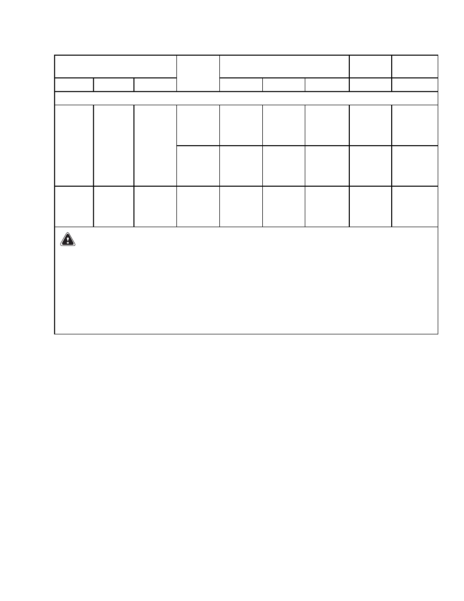
J2.00XMT TRUCK CAPACITY 2000 kg (4409 lb) - WHEEL BASE 1495 mm (58.9 in.)
48/BS
980 mm
(38.6 in.)
632 mm
(24.9 in.)
655 mm
(25.8 in.)
1110 to
1210 kg
(2447 to
2668 lb)
2014633
990 mm
(39.0 in.)
721 mm
(28.4 in.)
676 mm
(26.6 in.)
36/BS
980 mm
(38.6 in.)
632 mm
(24.9 in.)
655 mm
(25.8 in.)
1110 to
1210 kg
(2447 to
2668 lb)
2014633
839 mm
(33.0 in.)
749 mm
(29.5 in.)
650 mm
(25.6 in.)
48/DIN
830 mm
(32.7 in.)
738 mm
(29.1 in.)
612 mm
(24.1 in.)
955 to
1055 kg
(2105 to
2326 lb)
2014634
WARNING
The battery must fit the battery compartment so that the battery restraint system will operate
correctly. Use the spacers designed by the Hyster Company to prevent the battery from moving
more than 13 mm (0.5 in.) in any horizontal direction.
NOTE:
Maximum tolerances are ±3 mm (±0.12 in.) for the size of the battery compartment. The battery
specification table shows the maximum size tolerances that will permit the battery to still fit into the battery
compartment.
1
Dimensions are for the battery compartment with the required platform and acid tray installed.
2
The battery heights listed in this table are the height of the battery from the bottom of the battery to the
top of the cells.
15

NOTES
____________________________________________________________
____________________________________________________________
____________________________________________________________
____________________________________________________________
____________________________________________________________
____________________________________________________________
____________________________________________________________
____________________________________________________________
____________________________________________________________
____________________________________________________________
____________________________________________________________
____________________________________________________________
____________________________________________________________
____________________________________________________________
____________________________________________________________
____________________________________________________________
____________________________________________________________
____________________________________________________________
____________________________________________________________
____________________________________________________________
16

TECHNICAL PUBLICATIONS
8000 SRM 586
3/02 (9/99)(1/96)(6/95) Printed in United Kingdom
Document Outline
- toc
Wyszukiwarka
Podobne podstrony:
1452930 8000SRM0680 (12 2002) UK EN
897457 8000SRM0488 (03 1992) UK EN
1526432 8000SRM1041 (07 2002) UK EN
1453608 1600SRM0687 (03 2002) UK EN
897983 1600SRM0655 (03 2002) UK EN
897875 8000SRM0616 (03 2005) UK EN
1482632 8000SRM0798 (03 2000) UK EN
897883 8000SRM0621 (03 1999) UK EN
1495208 8000SRM0949 (03 2005) UK EN
1458783 8000SRM0592 (03 2005) UK EN
897458 8000SRM0489 (02 2002) UK EN
więcej podobnych podstron