CAPACITIES AND
SPECIFICATIONS
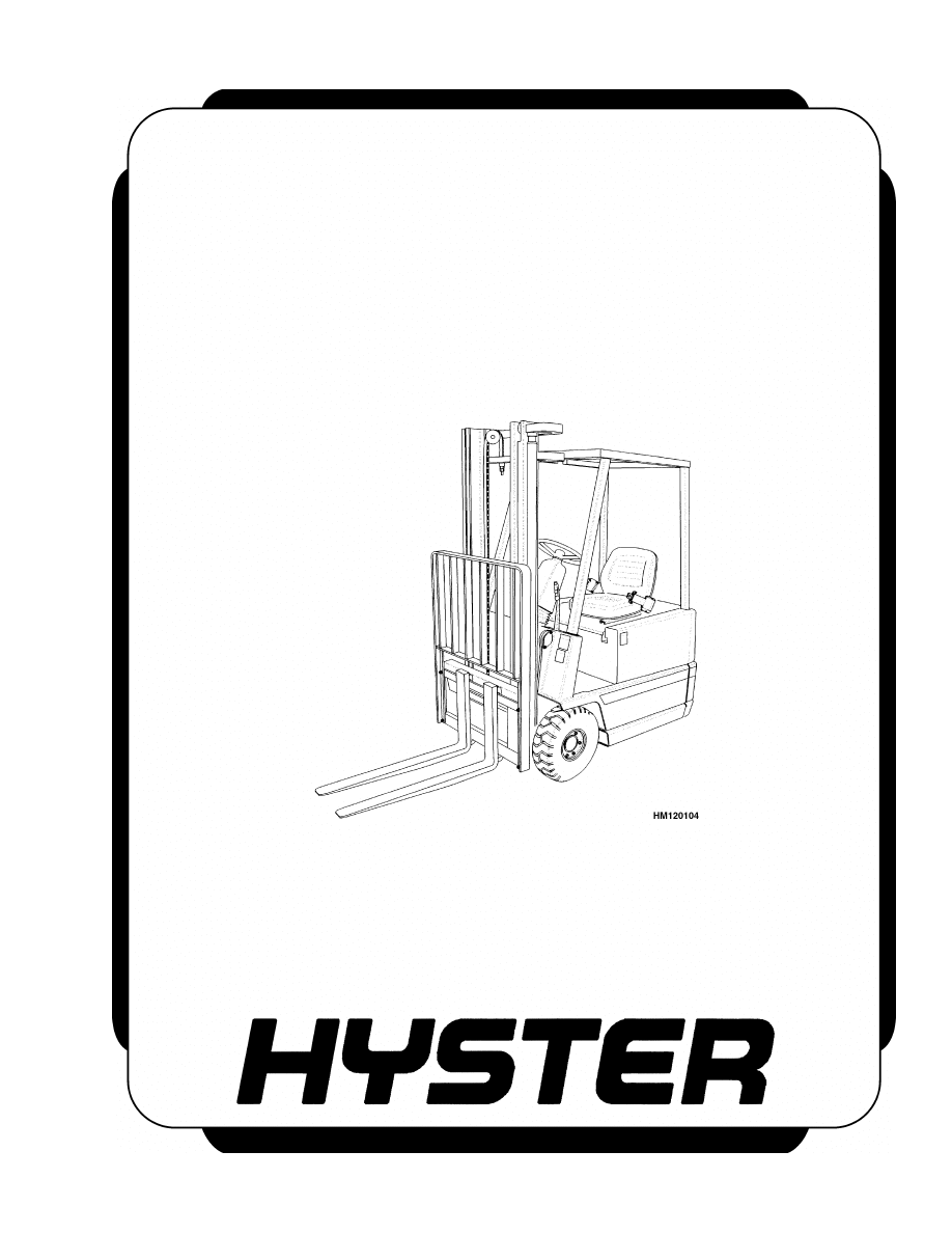
A1.00-1.50XL (A20-30XL) [C203]
PART NO. 1482635
8000 SRM 804

SAFETY PRECAUTIONS
MAINTENANCE AND REPAIR
• When lifting parts or assemblies, make sure all slings, chains, or cables are correctly
fastened, and that the load being lifted is balanced. Make sure the crane, cables, and
chains have the capacity to support the weight of the load.
• Do not lift heavy parts by hand, use a lifting mechanism.
• Wear safety glasses.
• DISCONNECT THE BATTERY CONNECTOR before doing any maintenance or repair
on electric lift trucks.
• Disconnect the battery ground cable on internal combustion lift trucks.
• Always use correct blocks to prevent the unit from rolling or falling. See HOW TO PUT
THE LIFT TRUCK ON BLOCKS in the Operating Manual or the Periodic Mainte-
nance section.
• Keep the unit clean and the working area clean and orderly.
• Use the correct tools for the job.
• Keep the tools clean and in good condition.
• Always use HYSTER APPROVED parts when making repairs. Replacement parts
must meet or exceed the specifications of the original equipment manufacturer.
• Make sure all nuts, bolts, snap rings, and other fastening devices are removed before
using force to remove parts.
• Always fasten a DO NOT OPERATE tag to the controls of the unit when making repairs,
or if the unit needs repairs.
• Be sure to follow the WARNING and CAUTION notes in the instructions.
• Gasoline, Liquid Petroleum Gas (LPG), Compressed Natural Gas (CNG), and Diesel fuel
are flammable. Be sure to follow the necessary safety precautions when handling these
fuels and when working on these fuel systems.
• Batteries generate flammable gas when they are being charged. Keep fire and sparks
away from the area. Make sure the area is well ventilated.
NOTE:
The following symbols and words indicate safety information in this
manual:
WARNING
Indicates a condition that can cause immediate death or injury!
CAUTION
Indicates a condition that can cause property damage!

Capacities and Specifications
Table of Contents
TABLE OF CONTENTS
Wheels and Tires................................................................................................................................................
Hydraulic System...............................................................................................................................................
Motors (24 Volt)..................................................................................................................................................
Mast Creep Speeds.............................................................................................................................................
Mast Speeds .......................................................................................................................................................
Battery Size Specifications ................................................................................................................................
Torque Specifications .........................................................................................................................................
Frame .............................................................................................................................................................
Master Drive Unit (MDU) (ZF Gotha)..........................................................................................................
Master Drive Unit (MDU) (Kordel) ..............................................................................................................
Steering System.............................................................................................................................................
Brake System.................................................................................................................................................
Hydraulic System ..........................................................................................................................................
Mast................................................................................................................................................................
Wheels ............................................................................................................................................................
Sevcon SC2126 Motor Controller Adjustments................................................................................................
This section is for the following models:
A1.00-1.50XL (A20-30XL) [C203]
©2002 HYSTER COMPANY
i

"THE
QUALITY
KEEPERS"
HYSTER
APPROVED
PARTS

8000 SRM 804
Mast Creep Speeds
Wheels and Tires
Model
Type
Size
Pressure
A1.00-1.50XL (A20-30XL)
Pneumatic Shaped Solid Tire
18 × 7-8
Not Applicable
Hydraulic System
Item
Specification
Hydraulic Tank Capacity (To FULL Mark)
8.3 liter (8.8 qt)
Hydraulic System Capacity
14.5 liter (15.3 qt)
Relief Valves Pressures*
Hydraulic System
17.2 MPa (2495 psi)
Secondary System
15.5 MPa (2248 psi)
Steering System
110 to 11.5 MPa (1595 to 1668 psi)
*Hydraulic Oil Temperature 50 C (122 F)
Motors (24 Volt)
Traction
Hydraulic
Rotation (From End of Shaft)
Two-Direction
Right
Winding
Series
Series
Number of Brushes
4
4
Mast Creep Speeds
Lift/Tilt
Creep Speeds
Lift at Carriage
* 100 mm (3.9 in.) in 10 minutes
Tilt at Carriage
*1.6 degrees in 10 minutes
*Hydraulic Oil Temperature 30 C (86 F).
Start measurement with mast at vertical position and the load raised to 2.5 m (8.2 ft).
Use maximum lift height if the maximum is less than 2.5 m (8.2 ft).
1
Mast Speeds
8000 SRM 804
Mast Speeds
Lifting*
Lowering*
No Load
Rated Load
No Load
Rated Load
Model
m/sec
ft/min
m/sec
ft/min
m/sec
ft/min
m/sec
ft/min
Two Stage Mast
A1.00XL (A20XL)
0.43
85
0.28
55
0.51
100
0.55
108
A1.25XL (A25XL)
0.43
85
0.26
51
0.51
100
0.55
108
A1.50XL (A30XL)
0.43
85
0.24
48
0.51
100
0.55
108
* Hydraulic Oil Temperature 30 C (86 F)
Lifting*
Lowering*
No Load
Rated Load
No Load
Rated Load
Model
m/sec
ft/min
m/sec
ft/min
m/sec
ft/min
m/sec
ft/min
Free-Lift Mast
A1.00XL (A20XL)
0.35
69
0.24
48
0.31
61
0.51
100
A1.25XL (A25XL)
0.35
69
0.23
45
0.31
61
0.51
100
A1.50XL (A30XL)
0.35
69
0.22
43
0.31
61
0.51
100
* Hydraulic Oil Temperature 30 C (86 F)
Lifting*
Lowering*
No Load
Rated Load
No Load
Rated Load
Model
m/sec
ft/min
m/sec
ft/min
m/sec
ft/min
m/sec
ft/min
Three-Stage Mast
A1.00XL (A20XL)
0.37
74
0.25
49
0.46
91
0.49
96
A1.25XL (A25XL)
0.37
74
0.23
45
0.46
91
0.49
96
A1.50XL (A30XL)
0.37
74
0.21
41
0.46
91
0.49
96
* Hydraulic Oil Temperature 30 C (86 F)
2
8000 SRM 804
Torque Specifications
Battery Size Specifications
Battery Size
Minimum/Maximum
Maximum
Minimum/Maximum
Model
Length
Width
Height
Weight
A1.00XL (A20XL)
486/497 mm
(18.9/19.5 in.)
825/830 mm
(32.5/32.6 in.)
680 mm (26.7 in.)
450/730 kg (992/1610 lb)
A1.25XL (A25XL)
486/497 mm
(18.9/19.5 in.)
825/830 mm
(32.5/32.6 in.)
680 mm (26.7 in.)
450/730 kg (992/1610 lb)
A1.50XL (A30XL)
486/497 mm
(18.9/19.5 in.)
825/830 mm
(32.5/32.6 in.)
680 mm (26.7 in.)
620/800 kg (1367/1764 lb)
NOTE:
Minimum gap is 4 mm (0.18 in.) and maximum gap is 18 mm (0.71 in.) for the size of the battery
compartment. The battery specification tables show the maximum size tolerances that will permit the bat-
tery to still fit into the battery compartment. The clearance between the battery lifting eyes and the hood
determine the minimum battery height.
WARNING
The battery must fit the battery compartment so that the battery restraint system will operate
correctly.
Torque Specifications
FRAME
Counterweight Capscrews
320 N•m (236 lbf ft)
Overhead Guard Capscrews
66 N•m (50 lbf ft)
MASTER DRIVE UNIT (MDU) (ZF GOTHA)
Hex Head Bolts Securing MDU to Lift
Truck Frame (6)
80 N•m (59 lbf ft)
Socket Head Capscrews Securing Traction
Motor to MDU (6)
23 N•m (17 lbf ft)
Wheel Lug Nuts (5)
140 N•m (103 lbf ft)
Oil Inlet Screw (1)
22 N•m (16 lbf ft)
Oil Outlet Screw (1)
22 N•m (16 lbf ft)
MASTER DRIVE UNIT (MDU) (KORDEL)
Nut On Helical Gear (1)
280 N•m (207 lbf ft)
Screws Holding Flange Shaft in Position (5)
130 N•m (96 lbf ft)
Oil Inlet Screw (1)
22 N•m (16 lbf ft)
Oil Outlet Screw (1)
22 N•m (16 lbf ft)
STEERING SYSTEM
Hydraulic Steering Motor
Capscrews for Flange Cover (6) 5 to
8 N•m (45 to 70 lbf in)
Capscrews for End Cover (7) 30 to 36 N•m
(22 to 25 lbf ft)
Drain Plug 25 to 30 N•m (18 to 22 lbf ft)
Gear Nut 100 N•m (74 lbf ft)
Hose Fittings to Steering Pump
9/16 UNF Fitting 25 N•m (18 lbf ft)
11/16 UNF Fitting 30 N•m (22 lbf ft)
3

Sevcon SC2126 Motor Controller Adjustments
8000 SRM 804
Steering Wheel Retaining Nut
40 to 54 N•m (30 to 40 lbf ft)
BRAKE SYSTEM
Vent Screw on Wheel Cylinder (1)
22 +13/ 0 N•m (16 +9.6 lbf ft)
Capscrews on Strap Plate Between
Brake Shoes (2)
10 ±2 N•m (88 ±17 lbf in)
Nut on Spindle of Load Wheel
68 N•m (50 lbf ft) Initial
3 N•m (2 lbf ft) Final
HYDRAULIC SYSTEM
Relief Valves (Main and Secondary)
20 to 24 N•m (15 to 18 lbf ft)
MAST
Capscrews for Mast Mounts, Cowl
51 N•m (38 lbf ft)
Capscrew and Nut for Rod End of Tilt Cylinder
90 N•m (66 lbf ft)
Capscrews for Sideshift Cylinder Mount
18 N•m (13 lbf ft)
Capscrews for Load Backrest
53 N•m (39 lbf ft)
Capscrews for Upper to Lower Apron
Weldments
435 N•m (320 lbf ft)
Sideshift Cylinder Glands
25 to 30 N•m (18 to 22 lbf ft)
WHEELS
Load and Steer Wheel (5 Per Wheel)
140 N•m (103 lbf ft)
Sevcon SC2126 Motor Controller Adjustments
The adjustments on the motor controller are set by
the manufacturer and must not be changed unless
the necessary equipment and trained personnel are
available. The parts of the controller and traction
circuit can be damaged by a wrong adjustment. See
Sevcon Motor Controller 2200 SRM 806 for addi-
tional information.
4

TECHNICAL PUBLICATIONS
8000 SRM 804
4/00 Printed in United Kingdom
Document Outline
- toc
Wyszukiwarka
Podobne podstrony:
1482632 8000SRM0798 (03 2000) UK EN
1482613 0630SRM0795 (04 2000) UK EN
1482638 8000SRM0805 (09 2005) UK EN
1482626 1900SRM0802 (04 2000) UK EN
1510478 8000SRM0988 (06 2005) UK EN
897653 1800SRM0566 (04 2005) UK EN
1554635 8000SRM1079 (06 2004) UK EN
1452930 8000SRM0680 (12 2002) UK EN
1565454 8000SRM1113 (06 2004) UK EN
897457 8000SRM0488 (03 1992) UK EN
więcej podobnych podstron