HYDRAULIC SYSTEM
A1.00-1.50XL (A20-30XL) [C203]
PART NO. 1482626
1900 SRM 802

SAFETY PRECAUTIONS
MAINTENANCE AND REPAIR
• When lifting parts or assemblies, make sure all slings, chains, or cables are correctly
fastened, and that the load being lifted is balanced. Make sure the crane, cables, and
chains have the capacity to support the weight of the load.
• Do not lift heavy parts by hand, use a lifting mechanism.
• Wear safety glasses.
• DISCONNECT THE BATTERY CONNECTOR before doing any maintenance or repair
on electric lift trucks.
• Disconnect the battery ground cable on internal combustion lift trucks.
• Always use correct blocks to prevent the unit from rolling or falling. See HOW TO PUT
THE LIFT TRUCK ON BLOCKS in the Operating Manual or the Periodic Mainte-
nance section.
• Keep the unit clean and the working area clean and orderly.
• Use the correct tools for the job.
• Keep the tools clean and in good condition.
• Always use HYSTER APPROVED parts when making repairs. Replacement parts
must meet or exceed the specifications of the original equipment manufacturer.
• Make sure all nuts, bolts, snap rings, and other fastening devices are removed before
using force to remove parts.
• Always fasten a DO NOT OPERATE tag to the controls of the unit when making repairs,
or if the unit needs repairs.
• Be sure to follow the WARNING and CAUTION notes in the instructions.
• Gasoline, Liquid Petroleum Gas (LPG), Compressed Natural Gas (CNG), and Diesel fuel
are flammable. Be sure to follow the necessary safety precautions when handling these
fuels and when working on these fuel systems.
• Batteries generate flammable gas when they are being charged. Keep fire and sparks
away from the area. Make sure the area is well ventilated.
NOTE:
The following symbols and words indicate safety information in this
manual:
WARNING
Indicates a condition that can cause immediate death or injury!
CAUTION
Indicates a condition that can cause property damage!

Hydraulic System
Table of Contents
TABLE OF CONTENTS
General ...............................................................................................................................................................
Description .........................................................................................................................................................
Control Valve Repair..........................................................................................................................................
Description .....................................................................................................................................................
Operation .......................................................................................................................................................
Lift..............................................................................................................................................................
Tilt and Auxiliary ......................................................................................................................................
Relief Valve ................................................................................................................................................
Check Valves..............................................................................................................................................
Description ............................................................................................................................................
Clean and Inspect .................................................................................................................................
Repairs ...........................................................................................................................................................
Remove.......................................................................................................................................................
Disassemble ...............................................................................................................................................
Relief Valve Repair ....................................................................................................................................
Clean and Inspect......................................................................................................................................
Assemble ....................................................................................................................................................
Install .........................................................................................................................................................
Checks ............................................................................................................................................................
Relief Valve Check.....................................................................................................................................
Adjust .............................................................................................................................................................
Relief Valve ................................................................................................................................................
Control Levers, Linkage and Switches ....................................................................................................
Hydraulic Pump Repair.....................................................................................................................................
Description .....................................................................................................................................................
Repairs ...........................................................................................................................................................
Remove.......................................................................................................................................................
Seal, Replace..............................................................................................................................................
Install .........................................................................................................................................................
Specifications......................................................................................................................................................
Relief Valves Pressures .................................................................................................................................
Hydraulic System Capacity...........................................................................................................................
Troubleshooting..................................................................................................................................................
Hydraulic Pump.............................................................................................................................................
Control Valve..................................................................................................................................................
This section is for the following models:
A1.00-1.50XL (A20-30XL) [C203]
©2002 HYSTER COMPANY
i

"THE
QUALITY
KEEPERS"
HYSTER
APPROVED
PARTS

1900 SRM 802
Description
General
This section describes the hydraulic system for the
A1.00-1.50XL (A20-30XL) series of lift trucks. The
repair procedure for the control valve is described in
this section. A description of the hydraulic pump is
included in this section. Repair procedures for the
hydraulic cylinders for the lift and tilt system are
described in the section Vista Masts Repairs 4000
SRM 374.
See the section Periodic Maintenance 8000 SRM
798 for information about changing the filter. See
the section Steering System 1600 SRM 796 for in-
formation on the power steering system. The Checks
and Troubleshooting for the hydraulic system are at
the end of this section.
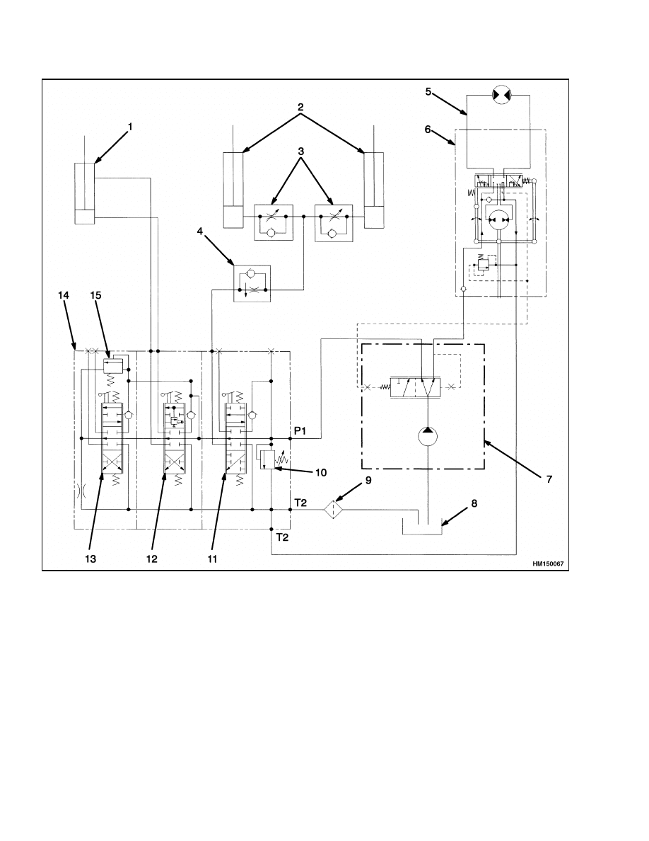
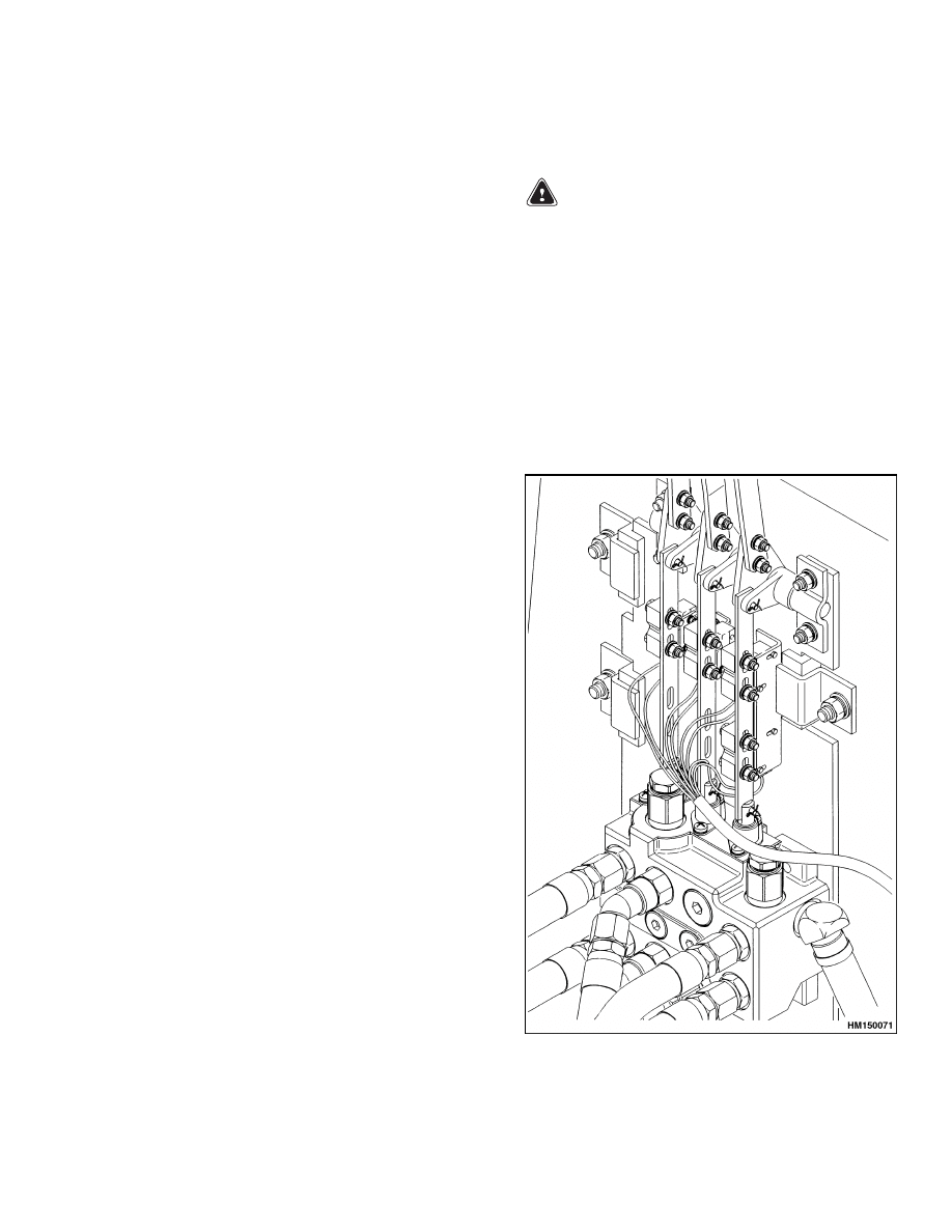
Description
Electric switches are actuated by the linkage for the
control valve to control the hydraulic pump motor.
See Figure 1.
The hydraulic motor operates to provide steering
when the seat switch or the start switch is closed.
When the seat switch is closed, the hydraulic lever
actuated switches increase the motor speed to pro-
vide the required flow for the hydraulic functions.
The control valve controls the operation of the lift,
tilt, and auxiliary cylinders. The lift truck is also
equipped with a single auxiliary hydraulic function.
The hydraulic pump receives hydraulic oil from the
hydraulic tank, and the flow divider diverts oil to the
steering control unit and through the control valve
to the lift and tilt system. The control valve controls
the flow of hydraulic oil to the lift, tilt, and auxil-
iary hydraulic cylinders. A relief valve in the control
valve controls the pressure within the design limits
of the lift system. A secondary relief valve controls
the hydraulic pressure in the tilt and auxiliary sys-
tems. Refer to Steering Control Unit 1600 SRM
797 for information on the operation of the steering
control unit.
The hydraulic oil returns from the control valve and
flows through a filter in the hydraulic tank. The filter
removes small particles from the hydraulic oil.
1
Description
1900 SRM 802
1.
TILT CYLINDER
2.
LIFT CYLINDERS
3.
SECONDARY LOWERING CONTROL VALVE
4.
PRIMARY LOWERING CONTROL VALVE
5.
HYDRAULIC STEERING MOTOR
6.
STEERING CONTROL UNIT
7.
PUMP FLOW DIVIDER
8.
HYDRAULIC TANK
9.
FILTER
10. RELIEF VALVE
11. LIFT AND LOWER SPOOL
12. TILT SPOOL
13. AUXILIARY CONTROL VALVE
14. HYDRAULIC CONTROL VALVE
15. SECONDARY RELIEF VALVE
Figure 1. Hydraulic System Schematic
2

1900 SRM 802
Control Valve Repair
Control Valve Repair
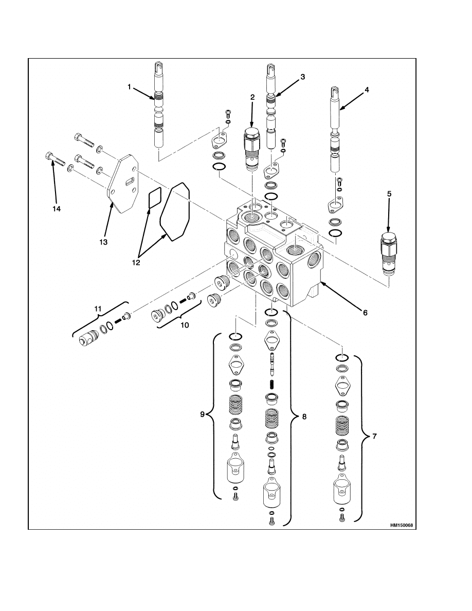
DESCRIPTION
The control valve controls the operation of the lift,
tilt, and auxiliary hydraulic functions. See Figure 2.
The control valve is fastened to the frame at the front
of the battery compartment.
The control valve has the following sections:
• Lift and lower
• Tilt
• Auxiliary
The spool is different for each function. Each func-
tion incorporates a load drop check valve.
Each spool has a centering spring that returns the
spool to the neutral position when the control lever
is released.
OPERATION
The main control valve is an open-center, series-par-
allel circuit valve. When open-center valve spools
are in the neutral position, the hydraulic oil flows
through the valve with minimum restriction. The
oil passes through the valve and returns to the hy-
draulic tank through the end section. When the lift
spool is completely shifted, no oil flows to other func-
tions. The tilt and auxiliary functions have a com-
mon feed and can operate simultaneously.
Lift
The lift function is configured as a series circuit. See
Figure 3 and Figure 4. As the spool is shifted to the
lift mode, the lift spool makes a restriction in the
open center passage. Increased pressure in the series
passage causes oil to flow through the check valve
to the supply cavity. The check valve prevents the
movement of the load until the system pressure is
great enough to control the load. When the lift spool
is fully shifted in the lift mode, oil supply is blocked
through the open center passage to the tilt and auxil-
iary function, forcing all flow to the lift circuit. When
the spool is in the lower position, the spool opens a
path from the lift cylinder to the drain cavity. The
spool is made so that the oil flow through the open
center passage is not stopped.
Tilt and Auxiliary
The tilt and auxiliary functions are configured as
parallel circuits. See Figure 3 and Figure 4. Each
spool can operate without preventing the flow of oil
to another spool. The parallel circuit also allows a
single relief valve to control the maximum pressure
of all functions in the circuit.
The operation of these spools is similar to that of the
lift spool. As the spool is shifted from the NEUTRAL
position, the flow through the open center passage is
restricted, increasing the system pressure. The in-
creased pressure in the series passage causes the oil
to flow through the check valve to the supply cavity.
The check valve prevents the movement of the load
until the system pressure is great enough to control
the load. When the spool is fully shifted, the paral-
lel flow path allows flow of oil to the other functions
in the parallel circuit. Flow from the tilt cylinders
or auxiliary attachments returns through the main
control valve to the hydraulic tank.
When tilting forward, an additional tilt control spool,
located inside the tilt spool, is used to prevent cavi-
tation in the piston end of the tilt cylinders. Cav-
itation occurs when the available fluid does not fill
the space in a closed system. When cavitation oc-
curs in the tilt cylinders, the tilt forward function is
not smooth. The tilt control spool permits the reg-
ulation of the tilt speed by using the pressure from
the hydraulic pump. The pump pressure must be at
least 800 kPa (115 psi) on the piston ends of the tilt
cylinders. The tilt control spool prevents oil flow from
the rod end of the tilt cylinder until the pressure is
800 kPa (115 psi). This action makes sure that a vac-
uum cannot occur at the piston ends of the tilt cylin-
ders.
3
Control Valve Repair
1900 SRM 802
Figure 2. Control Valve Exploded View
4
1900 SRM 802
Control Valve Repair
Legend for Figure 2
1.
AUXILIARY SPOOL
2.
PRIMARY RELIEF VALVE
3.
TILT SPOOL
4.
LIFT SPOOL
5.
SECONDARY RELIEF VALVE
6.
CONTROL VALVE BODY
7.
LIFT SECTION
8.
TILT SECTION
9.
AUXILIARY SECTION
10. LOAD CHECK VALVE
11. LOAD CHECK VALVE
12. SEALS
13. END PLATE
14. CAPSCREWS (3)
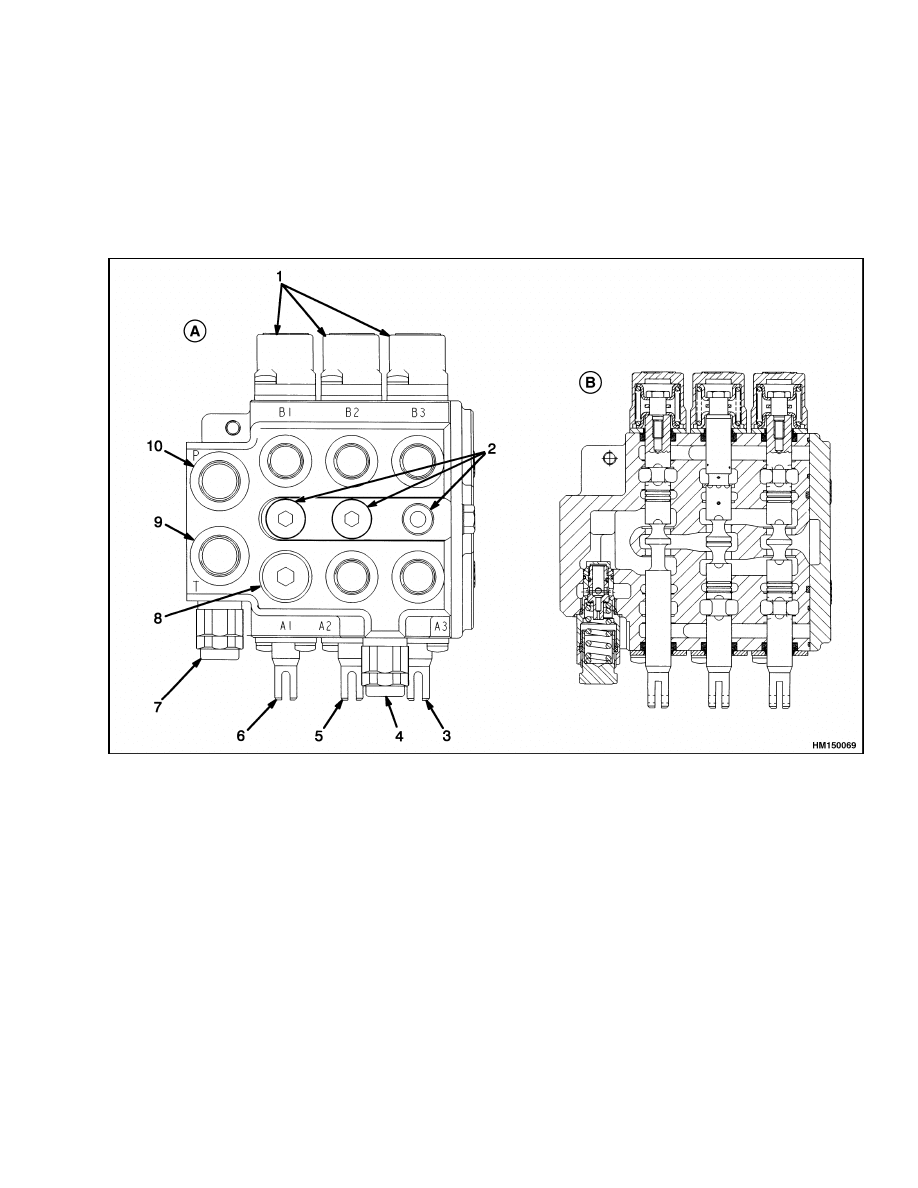
A. SIDE VIEW
B. CROSS SECTION OF VIEW TO THE LEFT SHOWS SPOOL AND RELIEF VALVE ARRANGEMENT
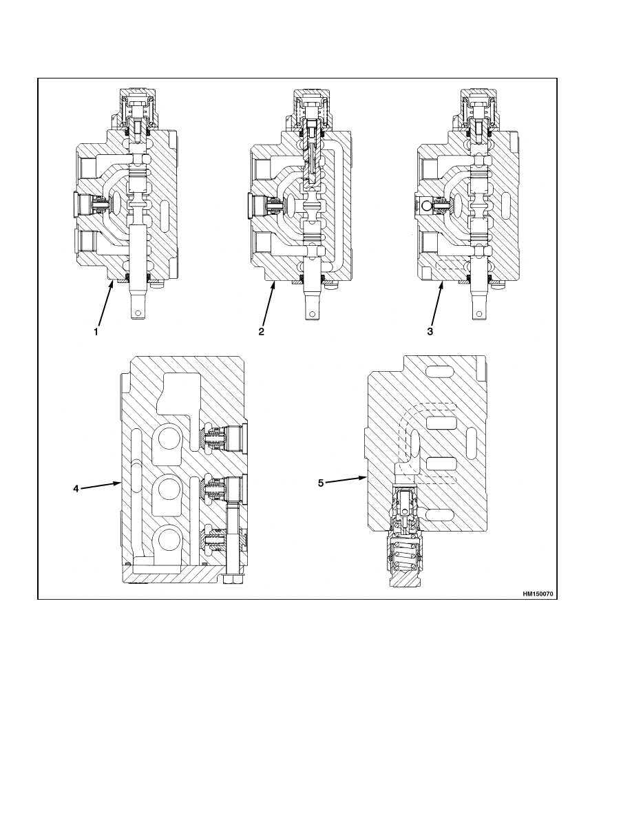
1.
END CAP SECTIONS
2.
CHECK VALVES
3.
AUXILIARY SPOOL
4.
SECONDARY RELIEF VALVE
5.
TILT SPOOL
6.
LIFT SPOOL
7.
PRIMARY RELIEF VALVE
8.
PLUG
9.
PUMP INPUT PORT
10. STEERING INPUT PORT
Figure 3. Control Valve
5
Control Valve Repair
1900 SRM 802
1.
LIFT SPOOL
2.
TILT SPOOL
3.
AUXILIARY SPOOL
4.
CHECK VALVES
5.
PRIMARY RELIEF VALVE
Figure 4. Control Valve Cross-Section Views
6
1900 SRM 802
Control Valve Repair
Relief Valve
The relief valve limits the maximum pressure within
the hydraulic system. See Figure 3 and Figure 4.
When the pressure in the hydraulic circuit reaches
the relief valve setting, the relief valve opens a path
between the inlet and drain circuits.
The relief valve uses a piston and a spring, which
gives a resistance to the pressure of the hydraulic
system. This relief valve gives almost constant relief
pressure over the range of flow from the hydraulic
pump.
Check Valves
Description
A check valve is installed in each spool section of the
control valve between the service ports. See Figure 3
and Figure 4. The check valves prevent load move-
ment on the function until the system hydraulic pres-
sure for that function is correctly applied. For exam-
ple, in the lift circuit, the check valve will not open
until the hydraulic pressure is greater than the ex-
isting hydraulic pressure in the lift cylinders. The
check valve prevents load movement on the function
until the system hydraulic pressure is high enough
to move the load. When the spool is in the neutral
position, the spool and check valve will prevent the
flow of hydraulic oil from the lift cylinders.
Clean and Inspect
1.
Remove the check valve cartridge from the sec-
tion of the control valve. Remove the poppet and
spring. See Figure 2.
2.
Clean the check valve cartridge. Check that the
poppet moves freely within the cartridge. Re-
place the check valve if it is damaged.
3.
Install the check valve cartridge into the section
of the control valve. Tighten the check valves to
20 to 24 N•m (15 to 18 lbf ft).
REPAIRS
Remove
WARNING
Make sure the mast is fully lowered before re-
moving the control valve. If a hydraulic line is
opened on a raised mast, the mast can suddenly
lower and cause injury.
1.
Disconnect the hydraulic lines at the control
valve. Put caps on the open hydraulic lines. See
Figure 5 and Figure 8.
2.
Disconnect the control linkage at the spools.
3.
Remove the capscrews that hold the mount plate
for the control valve to the frame and remove the
control valve from the lift truck.
Figure 5. Control Valve Linkage
7
Control Valve Repair
1900 SRM 802
Disassemble
NOTE: Disassemble the control valve as necessary
for repairs. See Figure 2. Most repairs to the con-
trol valve are in the adjustment of the linkage and
the replacement of O-rings to stop leaks. The small
passages in the tilt spool can need cleaning if the hy-
draulic oil becomes dirty. The control valve must be
replaced if the control spool or valve section is dam-
aged. The O-rings in the relief valve can be replaced
if necessary.
WARNING
The special capscrew in the end of the tilt spool
also holds the spring seats. The spring is com-
pressed. Make sure that the spring pressure is
controlled during disassembly so that the parts
are not suddenly released and cause injury.
1.
Remove the tilt control spool by removing the
special capscrew in the end of the tilt spool. Care-
fully remove the tilt control spool and spring from
the tilt spool.
2.
Remove the relief valve cartridge and repair or
replace as necessary. See Relief Valve Repair.
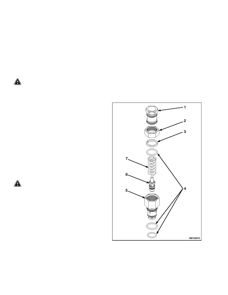
Relief Valve Repair
Repair of the relief valve is limited to replacement
of the seals on the relief valve assembly. The seal
on the piston is not replaceable. If the seal on the
piston is worn or damaged, replace the relief valve.
The serviceable seals are shown in Figure 6.
WARNING
Hydraulic oil can be hot. Make sure that the
hydraulic oil has cooled before removing the
relief valve.
Never adjust relief valves while the lift truck is
running.
Never adjust the relief valves above the recom-
mended settings. See at the end of this manual.
NOTE:
Make sure that hydraulic pressure has been
released before removing the relief valve.
1.
Remove the relief valve from the control valve.
NOTE:
Before disassembling the relief valve, match-
mark the adjuster cap and the relief valve body and
count the number of turns used to remove the ad-
juster cap.
2.
Loosen the lock nut and disassemble the relief
valve as shown in Figure 6.
3.
Replace the seal and O-rings. Do not replace the
piston seal. If the piston seal is worn or damaged,
replace the relief valve.
4.
Assemble the relief valve and install the ad-
juster cap the number of turns noted during
removal. Tighten the lock nut to 9 to 12 N•m
(80 to 106 lbf in).
5.
Install the relief valve into the control valve and
tighten to 20 to 24 N•m (15 to 18 lbf ft).
6.
Check and adjust the hydraulic pressure as nec-
essary. See Checks and Adjust.
1.
ADJUSTER CAP
2.
LOCK NUT
3.
SEAL
4.
O-RING
5.
VALVE BODY
6.
PISTON
7.
SPRING
Figure 6. Relief Valve Repair
8
1900 SRM 802
Control Valve Repair
Clean and Inspect
WARNING
Compressed air can move particles so that they
cause injury to the user or to other personnel.
Make sure that the path of the compressed air
is away from all personnel.
Wear protective
goggles or a face shield to prevent injury to the
eyes.
WARNING
Cleaning solvents can be flammable and toxic
and can cause skin irritation.
When using
cleaning solvents, always follow the solvent
manufacturer’s recommended safety precau-
tions.
Clean all parts of the control valve with solvent. Dry
the parts with compressed air.
Inspect the control spools and bores for defects. If a
control spool or a bore is damaged, then replace the
complete control valve. Make sure that the spools
move freely in their bores.
Inspect the check valves and relief valve for damage.
Replace the parts as necessary.
Assemble
1.
Lubricate all parts with clean hydraulic oil dur-
ing assembly. See Figure 2.
2.
Install new seals in the valve body. Install the
endplate and install the three capscrews.
3.
If the centering springs were removed from the
control spools, install the spring seats, spacers,
and springs to the ends of the control spools. Dur-
ing assembly, use new seals and wiper seals for
the parts of the tilt control spool. Do not damage
the seals during installation.
4.
Lubricate the control spools with clean hydraulic
oil. Carefully install the control spools in the
valve body. Install the wiper seal plates and the
end caps for the return springs.
NOTE:
The adjustment for the relief valve is set by
the manufacturer. Do not change the adjustment un-
less you are sure that the adjustment is not correct.
5.
Install the relief valve into the control valve and
tighten the relief valve to 20 to 24 N•m (15 to
18 lbf ft).
6.
Check and adjust the setting of the relief valve
for the hydraulic system as described in Checks
and Adjust.
Install
1.
Install the control valve on the mount plate and
fasten the control valve to the frame. See Fig-
ure 8.
2.
Connect the control linkage at the spools.
3.
Connect the hydraulic lines to the control valve.
4.
Add the hydraulic oil to the tank.
See Peri-
odic Maintenance 8000 SRM 798 for the cor-
rect specifications.
5.
Operate the system and check for leaks and
correct operation.
Adjust the relief valve as
described in Adjust.
CHECKS
Relief Valve Check
1.
Turn the lift truck off and release all pressure in
the hydraulic system.
2.
Connect a 0 to 20 MPa (0 to 3000 psi) pressure
gauge to a T-fitting inserted between the pump
supply line and the control valve.
3.
Start the truck and check the operation of the
relief valve when the hydraulic oil temperature is
55 to 65 C (130 to 150 F). Operate the hydraulic
system so that the oil temperature will be within
the normal operating range before making the
pressure checks. See Specifications at the end of
this manual for the correct setting. If the relief
valve does not meet the specifications, shut down
the truck and adjust the relief valve. See Adjust.
Completely lower the mast before replacing the
relief valve.
4.
Tilt the mast backward until it stops. Hold the
control lever in the TILT BACKWARD position
and check the indication of the pressure gauge
when the relief valve opens. See the Specifica-
tions for the correct setting. If the relief valve
does not meet the specifications, adjust the relief
valve. See Adjust. Completely lower the mast
before replacing the relief valve.
5.
Remove the pressure gauge when the checks
have been completed.
9
Control Valve Repair
1900 SRM 802
ADJUST
Relief Valve
WARNING
Never adjust relief valves while the lift truck is
running.
Never adjust the relief valves above the recom-
mended settings. See Specifications at the end
of this manual.
If the relief valve does not meet the specifications
when checked, adjust the relief valve as follows.
1.
Connect a 0 to 20 MPa (0 to 3000 psi) pressure
gauge to a T-fitting inserted between the pump
supply line and the control valve.
2.
Make sure that the hydraulic oil temperature is
55 to 65 C (130 to 150 F).
3.
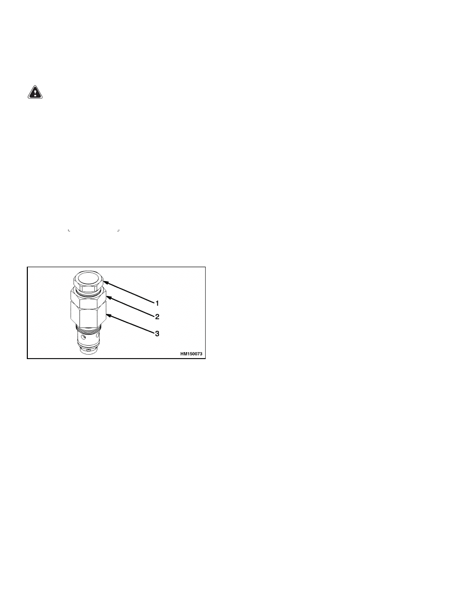
Loosen the lock nut on the relief valve. See Fig-
ure 7.
1.
ADJUSTER CAP
2.
LOCK NUT
3.
VALVE BODY
Figure 7. Relief Valve Adjustment
4.
Adjust the pressure by rotating the adjuster cap
clockwise to increase the pressure or counter-
clockwise to decrease the pressure. Adjust the
cap in increments of one-quarter turn.
5.
While holding the adjuster cap in place, tighten
the lock nut to 9 to 12 N•m (80 to 106 lbf in).
6.
Check the oil pressure. If the pressure is not
correct, repeat Step 3 through Step 5.
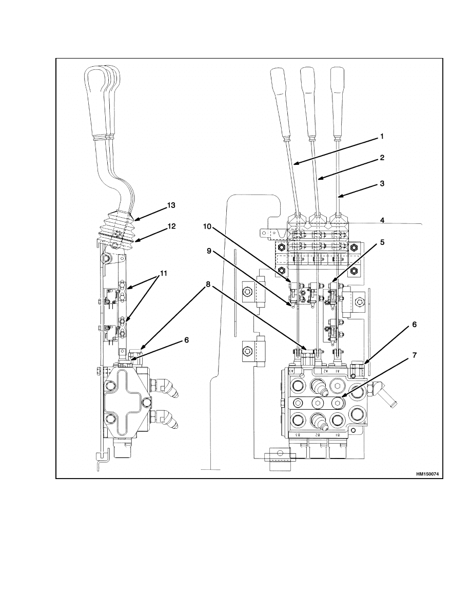
Control Levers, Linkage and Switches
The LIFT and LOWER function and the TILT func-
tion have separate control levers. The control spools
for the control valve must be in the NEUTRAL
(open-center) position. Loosen the bolts and adjust
the length of the links so that the hand levers are
in the correct position for operation as shown in
Figure 8. The handle position is adjusted using the
handle mounting capscrews. The upper hole is over-
sized, which allows the angle to be adjusted. The
auxiliary handle should be adjusted as far backward
as possible without interfering with the hood, the lift
handle should be adjusted as far forward as possible,
and the tilt handle should be adjusted in the middle.
Check that the electric microswitches are adjusted
correctly. Loosen the bolts that hold the microswitch
actuator to the linkage. Slide the microswitch actu-
ator so that the microswitch roller is in the center of
the detent in the actuator. Check the clearance be-
tween the microswitch roller and the actuator. Move
the actuator or loosen and move the microswitch so
that there is a 0.5 to 1.0 mm (0.020 to 0.040 in.) clear-
ance between the microswitch roller and the actua-
tor. Tighten the bolts when the microswitches have
been correctly adjusted.
NOTE: There are two detents on the actuators
for the microswitches. One detent is only for the
LIFT function and the actuator does not close the
microswitch when the LOWER function is used. The
other detent in the actuator closes the microswitch
when the link is moved in either direction. If an
actuator is replaced on a link, make sure that the
correct detent faces the microswitch for that func-
tion.
10
1900 SRM 802
Control Valve Repair
1.
AUXILIARY CONTROL LEVER
2.
CONTROL LEVER, TILT
3.
CONTROL LEVER, LIFT AND
LOWER
4.
TILT ACTUATOR
5.
LIFT ACTUATOR
6.
RELIEF VALVE
7.
TEST PORT
8.
SECONDARY RELIEF VALVE
9.
MICROSWITCH
10. AUXILIARY ACTUATOR
11. DETENTS
12. STIFFENER
13. BELLOWS
Figure 8. Linkage and Microswitch Adjustment
11
Hydraulic Pump Repair
1900 SRM 802
Hydraulic Pump Repair
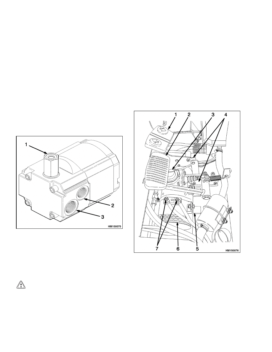
DESCRIPTION
The hydraulic pump and flow divider is a one-section
gear pump fastened to the end of the pump motor
housing. See Figure 9. One pump outlet from the
flow divider is connected to a hydraulic hose that goes
to the control valve. A coupling connects the motor
shaft to the pump shaft. The motor shaft and the
pump shaft each have a machined area that engages
the coupling. The bushings installed at the sides of
the gears inside of the pump are the bearings for the
gear shafts. The bushings also have passages for the
oil flow to the pump outlet and for lubrication. Seals
prevent leaks between sections of the pump housing.
The priority output from the flow divider goes to the
input of the steering control unit. See Steering Con-
trol Unit 1600 SRM 797.
1.
LOAD SENSING
PORT
2.
PRIORITY PORT
3.
EXCESS FLOW
PORT
Figure 9. Hydraulic Pump and Flow Divider
REPAIRS
Remove
CAUTION
If the battery is installed during maintenance
and repairs, install an insulator cover over the
battery. Metal parts and tools can cause a short
circuit and cause damage.
NOTE:
Seals that are worn or damaged are the most
common cause of pump repair. The pump bearings,
gears, and shafts also wear. Most service persons do
not repair a pump that is worn. The cost of repairs
can be greater than the cost of a new pump. The seals
can be replaced in the hydraulic pump. Replace a
worn or damaged hydraulic pump.
The hydraulic pump and motor are fastened to the
frame under the pedal assembly for the brake and
the accelerator. See Figure 10. The hydraulic pump
and motor are normally removed as a unit for repairs.
1.
MONOTROL PEDAL
2.
BRAKE PEDAL
3.
MASTER CYLINDER
4.
PEDAL MOUNT BRACKET
5.
MOTOR MOUNT
6.
HYDRAULIC PUMP AND MOTOR
7.
POWER TERMINALS
Figure 10. Hydraulic Pump and Motor
12

1900 SRM 802
Hydraulic Pump Repair
1.
Remove the capscrew and nuts that hold the
mounting brackets for the brake pedal, master
cylinder, and accelerator pedal to the frame.
Remove the return spring from the brake pedal.
Disconnect the brake line from the master cylin-
der. Remove the pedal assemblies.
2.
Disconnect the power cables to the hydraulic
pump motor.
3.
Remove the straps that hold the hydraulic pump
and motor to the mount on the frame. Loosen the
outlet hose to the hydraulic pump first when the
pump is removed for repair. When air enters the
outlet hose, most of the hydraulic oil drains to the
hydraulic tank and reduces the loss of oil from
the system. Remove the inlet and outlet hoses.
Put caps over the ends of the hoses to prevent
dirt from entering the hydraulic system.
4.
Remove the two through bolts that hold the hy-
draulic pump to the motor. Do not remove the
other two capscrews that fasten the hydraulic
pump together. The coupling will slide from the
pump and motor shafts when the hydraulic pump
is removed from the motor housing.
Seal, Replace
NOTE:
If the hydraulic pump is held in a vise for dis-
assembly, use soft jaws in the vise. Make sure the
vise does not hold the hydraulic pump too tightly and
cause distortion of the pump housing.
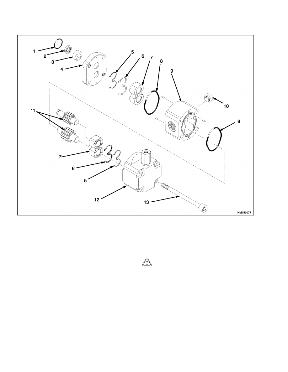
There are two models of pump used in this lift truck,
one manufactured by Barnes (Figure 11) and one
manufactured by Ultra (Figure 12).
Make notes of the location of the parts and seals dur-
ing disassembly. Some of the parts are similar and it
can be difficult to make an identification if they are
mixed.
1.
Make a mark on the housings to aid in assembly.
2.
Carefully remove the end covers. Make a note
of the seal arrangement. Do not disassemble the
pump gear assembly.
3.
Carefully remove the oil seals from the bushings
and pump housing.
4.
Inspect the pump gear assembly and the pump
housing for wear and damage. Replace a dam-
aged or worn hydraulic pump.
NOTE:
Some pump housings will show gear marks.
These marks are caused by the small clearances be-
tween the parts. These gear marks do not indicate
a worn or damaged hydraulic pump unless the pump
will not supply the volume and pressure shown in the
specifications.
5.
Make sure the internal parts of the hydraulic
pump have been cleaned. Lubricate the parts
with hydraulic oil as they are installed into the
pump.
Install new seals in the bushings and
pump housing.
6.
Install the gears and bushing assembly in the
pump housing.
Make sure each bushing is
aligned correctly.
7.
Install the seal rings and support ring (see the
arrangement in Figure 11 and Figure 12) to the
outer end of the pump. Install the end cover and
the two capscrews to the pump housing.
8.
Install the seal rings and the support ring in the
end of the pump toward the motor. Install the
end cover.
9.
Make sure that all of the parts of the hydraulic
pump are in the correct position for installation
on the motor.
10. Install the coupling on the motor shaft. Install
the hydraulic pump on the motor and fasten
with the two through bolts. Tighten the bolts to
47 N•m (35 lbf ft).
13
Hydraulic Pump Repair
1900 SRM 802
1.
O-RING
2.
SHAFT SEAL
3.
COUPLING
4.
MOUNTING FLANGE
5.
BACKUP RING
6.
BUSHING SEAL
7.
BUSHING
8.
O-RING
9.
BODY
10. PLUG
11. GEAR
12. BODY
13. THROUGH BOLT
Figure 11. Pump Flow Divider (Barnes)
Install
1.
Install the hydraulic pump and motor assembly
to the mount on the lift truck frame. Fasten the
straps around the pump motor.
2.
Add oil to the hydraulic pump before the out-
put fitting is installed on the top of the pump.
This procedure will make sure the pump has hy-
draulic oil for first operation.
3.
Install the hydraulic hoses to the inlet and the
outlet ports on the hydraulic pump. Make sure
the hoses and the ports are clean.
CAUTION
Be sure to remove any air that may have en-
tered the brake system if the brake line was re-
moved from the master cylinder. See the sec-
tion Brake System 1800 SRM 803.
4.
Install the pedal assemblies to their original po-
sition in the frame. Fasten the mounting brack-
ets in position with the capscrews and nuts. In-
stall the brake line to the master cylinder.
14
1900 SRM 802
Hydraulic Pump Repair
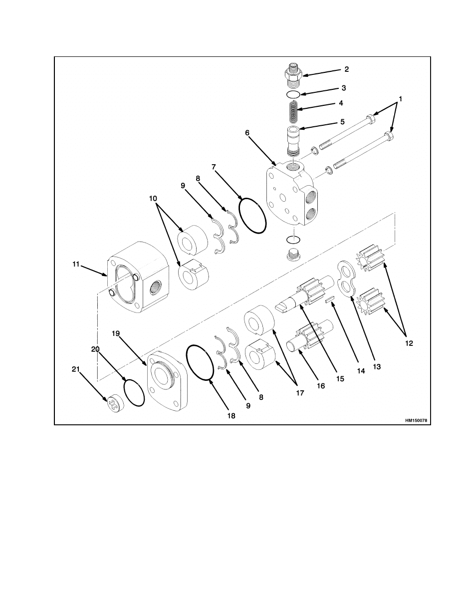
1.
THROUGH BOLTS
2.
SPRING SEAT
3.
SEAL
4.
SPRING
5.
SPOOL ASSEMBLY
6.
BODY
7.
O-RING
8.
BACKUP RING
9.
BUSHING SEAL
10. BUSHING
11. BODY
12. GEARS
13. PLATE
14. WOODRUFF KEY
15. DRIVE GEAR
16. IDLER GEAR
17. BUSHINGS
18. O-RING
19. END FLANGE
20. O-RING
21. FITTING
Figure 12. Pump Flow Divider (Ultra)
15
Troubleshooting
1900 SRM 802
Specifications
RELIEF VALVES PRESSURES
Hydraulic System
17.2 MPa (2495 psi)
Secondary Relief Valve
15.5 MPa (2248 psi)
HYDRAULIC SYSTEM CAPACITY
Hydraulic Tank to FULL Mark
8.3 liter (8.8 qt)
Hydraulic System
14.5 liter (15.3 qt)
*All measurements made when the hydraulic oil temperature is 54 to 66 C (130 to 150 F).
Troubleshooting
HYDRAULIC PUMP
PROBLEM
POSSIBLE CAUSE
PROCEDURE OR ACTION
Hydraulic pressure is low.
Hydraulic pump is worn or damaged.
Replace pump.
Relief valve needs adjustment.
Adjust or replace relief valve.
Relief valve for the hydraulic
system opens frequently.
Relief valve needs adjustment or is
defective.
Adjust or replace relief valve.
Hydraulic hoses are too small for the
hydraulic attachment.
Install correct size hydraulic hoses.
Pump noise is not normal.
Hydraulic tank oil level is low.
Fill hydraulic tank with oil.
Inlet hose is restricted.
Disconnect hose and remove restric-
tion.
Loose inlet fitting.
Tighten inlet fitting to correct torque.
Damaged bearings or gears.
Replace hydraulic pump.
Loose bolts around motor or pump.
Tighten all bolts to correct torque.
Pump is worn or damaged.
Repair or replace pump.
Pump motor is worn or damaged.
Repair or replace motor.
16

1900 SRM 802
Troubleshooting
PROBLEM
POSSIBLE CAUSE
PROCEDURE OR ACTION
Hydraulic pump has low out-
put.
Pump is worn or damaged.
Repair or replace pump.
Seals or gaskets are damaged and
cause leaks.
Replace seals and gaskets.
Pump fitting has a leak.
Replace O-ring on fitting.
Control valve linkages or switches
need adjustment.
Adjust linkage or switches.
Pump has leaks.
Fittings are loose or defective.
Repair or replace fitting. Tighten to
correct torque.
Loose pump housing bolts.
Tighten pump housing bolts to cor-
rect torque.
Defective seals.
Replace defective seals.
CONTROL VALVE
PROBLEM
POSSIBLE CAUSE
PROCEDURE OR ACTION
Oil leaks at the end of the
spools.
Spool seals have defects.
Replace seals.
Spool has a defect.
Replace valve.
Valve body has a defect.
Replace valve.
Spool will not move.
Defect in linkage.
Repair or replace linkage.
Dirt between spool and bore.
Clean valve and spool.
Spool is bent or damaged.
Replace valve.
Spool does not return to neu-
tral.
Defect in linkage.
Repair or replace linkage.
Return spring is damaged.
Replace return spring.
Spool is bent or damaged.
Replace valve.
17

Troubleshooting
1900 SRM 802
PROBLEM
POSSIBLE CAUSE
PROCEDURE OR ACTION
Cylinder movement is slow
or nonexistent.
Defect in linkage.
Repair or replace linkage.
Defect in relief valve.
Replace relief valve.
Large leaks between spool and bore.
Replace seals or replace valve.
Spool is not fully extended or re-
tracted.
Replace valve.
Restriction in hydraulic lines.
Disconnect hydraulic lines and re-
move restriction.
Load is greater that capacity.
Reduce size of load.
Hydraulic pressure is high.
Defective cylinder seals.
Replace cylinder seals.
Relief valve needs adjustment or is
damaged.
Adjust or replace relief valve.
Restriction in return line.
Disconnect return line and remove
restriction.
The cylinder extends when
the tilt spool is in NEU-
TRAL.
Defective cylinder seals.
Replace cylinder seals.
Relief valve needs adjustment or is
damaged.
Adjust or replace relief valve.
Hydraulic lines have leaks.
Replace hydraulic lines.
Tilt cylinder extends sud-
denly when tilt spool is
moved to the TILT BACK-
WARD position.
Defective tilt spool check valve.
Replace tilt spool check valve.
Tilt cylinder extends sud-
denly when tilt spool is
moved to the TILT FOR-
WARD position.
Defective tilt control spool inside tilt
spool.
Replace control valve.
18

1900 SRM 802
Troubleshooting
PROBLEM
POSSIBLE CAUSE
PROCEDURE OR ACTION
Lift cylinder retracts when
lift spool is moved to the
LIFT position.
Defective lift spool check valve.
Replace lift spool check valve.
Lift cylinder retracts when
lift spool is moved to the
NEUTRAL position.
Cylinder seals have leaks.
Replace cylinder seals.
Hydraulic line has leaks.
Replace hydraulic line.
Large leak between lift spool and
bore.
Replace control valve.
19

NOTES
____________________________________________________________
____________________________________________________________
____________________________________________________________
____________________________________________________________
____________________________________________________________
____________________________________________________________
____________________________________________________________
____________________________________________________________
____________________________________________________________
____________________________________________________________
____________________________________________________________
____________________________________________________________
____________________________________________________________
____________________________________________________________
____________________________________________________________
____________________________________________________________
____________________________________________________________
____________________________________________________________
____________________________________________________________
____________________________________________________________
20

TECHNICAL PUBLICATIONS
1900 SRM 802
4/00 Printed in United Kingdom
Document Outline
- toc
Wyszukiwarka
Podobne podstrony:
897068 1900SRM0286 (07 2000) UK EN
1482635 8000SRM0804 (04 2000) UK EN
1482623 1800SRM0803 (03 2000) UK EN
1482620 1600SRM0796 (03 2000) UK EN(1)
1482613 0630SRM0795 (04 2000) UK EN
897068 1900SRM0286 (07 2000) UK EN
1564283 1900SRM1107 (01 2004) UK EN
897653 1800SRM0566 (04 2005) UK EN
910091 1900SRM0097 (08 2005) UK EN
1598459 1900SRM1213 (03 2005) UK EN
897394 1900SRM0453 (09 2003) UK EN
więcej podobnych podstron