STEERING AXLE
RS45-30CH, RS45-27IH, RS46-33CH, RS46-30IH,
RS46-36CH, RS46-33IH [A222]
PART NO. 897953
1600 SRM 639
SAFETY PRECAUTIONS
MAINTENANCE AND REPAIR
• When lifting parts or assemblies, make sure all slings, chains, or cables are correctly
fastened, and that the load being lifted is balanced. Make sure the crane, cables, and
chains have the capacity to support the weight of the load.
• Do not lift heavy parts by hand, use a lifting mechanism.
• Wear safety glasses.
• DISCONNECT THE BATTERY CONNECTOR before doing any maintenance or repair
on electric lift trucks. Disconnect the battery ground cable on internal combustion lift
trucks.
• Always use correct blocks to prevent the unit from rolling or falling. See HOW TO PUT
THE LIFT TRUCK ON BLOCKS in the Operating Manual or the Periodic Mainte-
nance section.
• Keep the unit clean and the working area clean and orderly.
• Use the correct tools for the job.
• Keep the tools clean and in good condition.
• Always use HYSTER APPROVED parts when making repairs. Replacement parts
must meet or exceed the specifications of the original equipment manufacturer.
• Make sure all nuts, bolts, snap rings, and other fastening devices are removed before
using force to remove parts.
• Always fasten a DO NOT OPERATE tag to the controls of the unit when making repairs,
or if the unit needs repairs.
• Be sure to follow the WARNING and CAUTION notes in the instructions.
• Gasoline, Liquid Petroleum Gas (LPG), Compressed Natural Gas (CNG), and Diesel fuel
are flammable. Be sure to follow the necessary safety precautions when handling these
fuels and when working on these fuel systems.
• Batteries generate flammable gas when they are being charged. Keep fire and sparks
away from the area. Make sure the area is well ventilated.
NOTE: The following symbols and words indicate safety information in this
manual:
WARNING
Indicates a condition that can cause immediate death or injury!
CAUTION
Indicates a condition that can cause property damage!
Steering Axle
Table of Contents
TABLE OF CONTENTS
General ...............................................................................................................................................................
Description .........................................................................................................................................................
How to Put ReachStacker on Blocks.................................................................................................................
How to Lift Steer Tires ..................................................................................................................................
Steering Axle Assembly .....................................................................................................................................
Up to 1527 ......................................................................................................................................................
Remove.......................................................................................................................................................
Install .........................................................................................................................................................
Starting With 1528 ........................................................................................................................................
Remove.......................................................................................................................................................
Install .........................................................................................................................................................
Wheels and Hubs ...............................................................................................................................................
Remove and Disassemble ..............................................................................................................................
Clean ..............................................................................................................................................................
Assemble and Install .....................................................................................................................................
Spindles, Bearings, and Tie Rods......................................................................................................................
Remove ...........................................................................................................................................................
Install .............................................................................................................................................................
Steering Cylinder ...............................................................................................................................................
Up to 1532 ......................................................................................................................................................
Remove and Disassemble..........................................................................................................................
Clean and Inspect......................................................................................................................................
Assemble and Install.................................................................................................................................
Starting With 1533 ........................................................................................................................................
Remove and Disassemble..........................................................................................................................
Clean and Inspect......................................................................................................................................
Assemble and Install.................................................................................................................................
Torque Specifications .........................................................................................................................................
Troubleshooting..................................................................................................................................................
This section is for the following models:
RS45-30CH, RS45-27IH, RS46-33CH, RS46-30IH, RS46-36CH,
RS46-33IH [A222]
©2005 HYSTER COMPANY
i

"THE
QUALITY
KEEPERS"
HYSTER
APPROVED
PARTS
1600 SRM 639
Description
General
This section has the description and repair procedures for the steering axle. For information on other parts of
the steering system, see the section Steering System 1600 SRM 637.
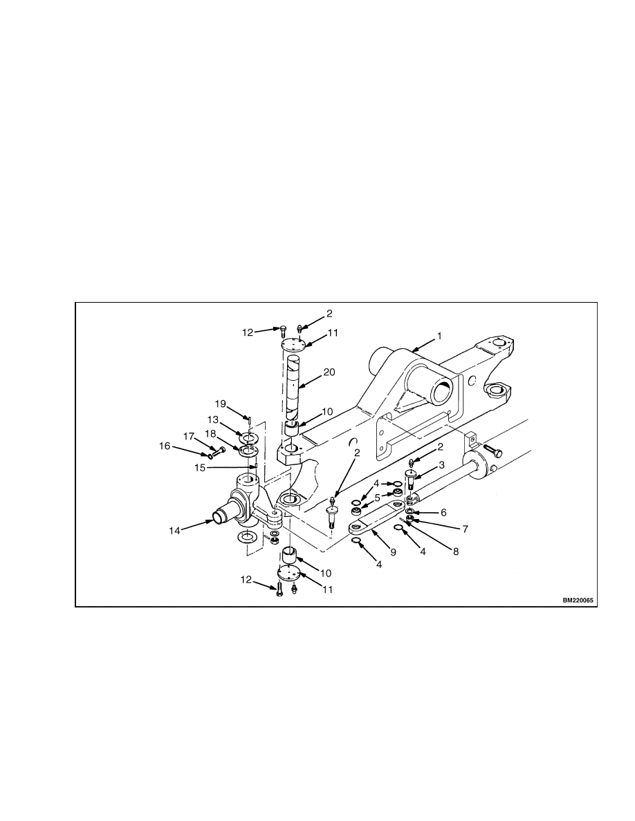
Description
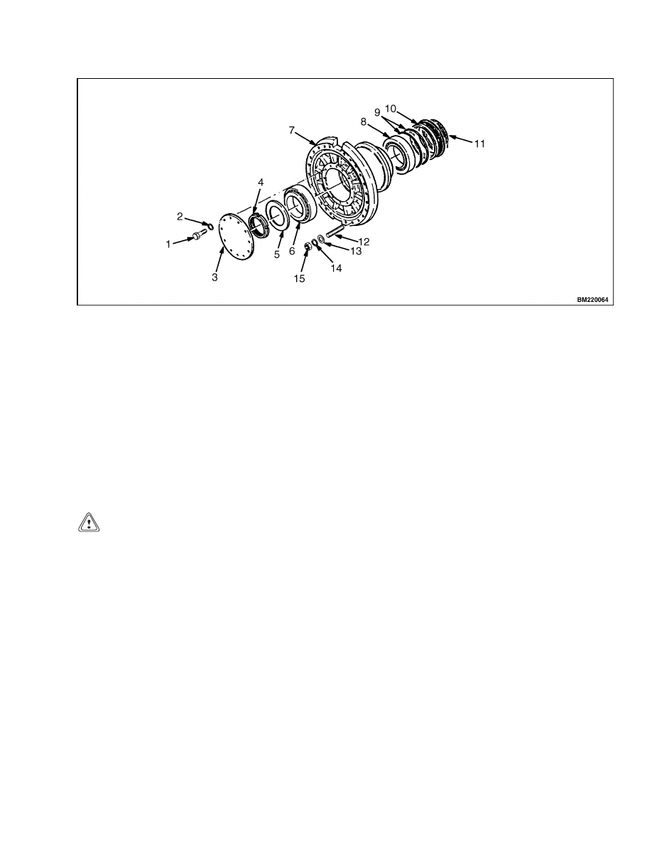
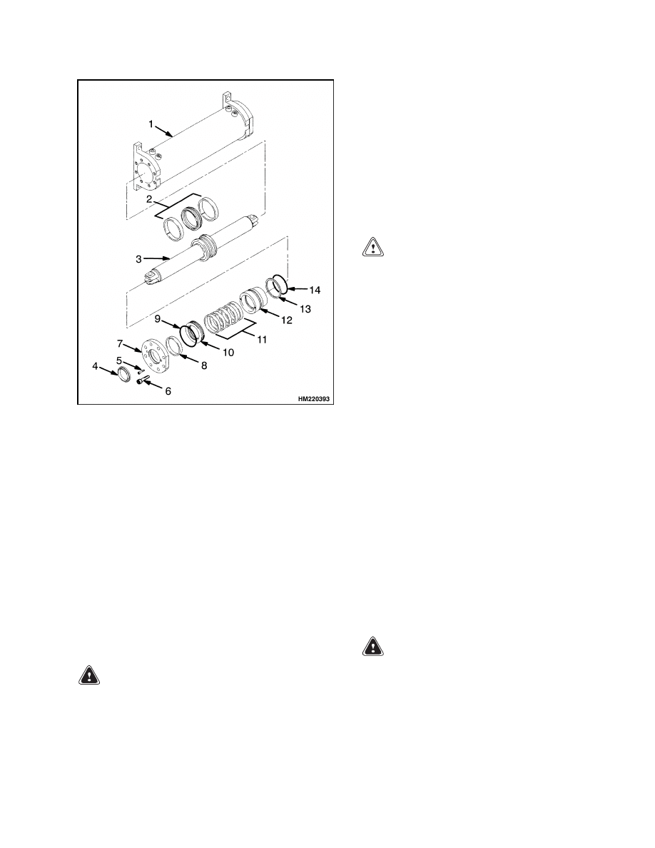
The steering axle assembly includes an axle housing,
steering cylinder, tie rods, tie rod pins, and two spin-
dle and hub assemblies. See Figure 1. The steering
axle mounts to the frame with a center pivot pin. The
center pivot pin permits the steering axle to move as
the ReachStacker
®
travels over rough surfaces.
The steering cylinder mounts to the axle housing
with four bolts. The ends of the piston rod extend
from both ends of the cylinder. A single piston and
the seal are at the center of the rod. Oil pressure on
one side of the piston moves the piston in the bore.
As the piston moves, it pushes an equal amount of
oil from the opposite end of the cylinder. The oil
returns to the steering control unit.
When the piston in the cylinder reaches the end of
the stroke, a relief valve limits the oil pressure so
the components are not damaged. The relief valve is
located in the flow amplifier.
1.
AXLE HOUSING
2.
GREASE FITTING
3.
PIN
4.
SNAP RING
5.
SPHERICAL BEARING
6.
WASHER
7.
LOCK NUT
8.
SPLIT PIN
9.
TIE ROD
10. BUSHING
11. PLATE
12. CAPSCREW
13. SHIM/THRUST WASHER
14. SPINDLE
15. ROLL PIN
16. WASHER
17. CAPSCREW
18. THRUST WASHER
19. GROOVE PIN
20. KING PIN
Figure 1. Steer Axle Assembly
1
Steering Axle Assembly
1600 SRM 639
Tie rods connect the steering cylinder to the spindles.
A king pin supports the spindle in the axle housing.
Each spindle turns on two bushings and thrust wash-
ers. Covers on the top and bottom of the axle housing
protect the king pins and bushings from dirt and wa-
ter.
The wheel hub rotates on two tapered roller bearings.
An adjustment nut sets the preload on the bearings.
Grease seals in the inner hub and a cover on the hub
protect the bearings from dirt and water.
How to Put ReachStacker on Blocks
HOW TO LIFT STEER TIRES
WARNING
The ReachStacker
®
must be put on blocks for
some types of maintenance and repair. The sur-
face must be solid, even, and level when the
ReachStacker is put on blocks. Verify that any
blocks used to support the ReachStacker are
solid, one-piece units. Verify the lifting devices
used during repairs can lift the weight of the
parts and assemblies.
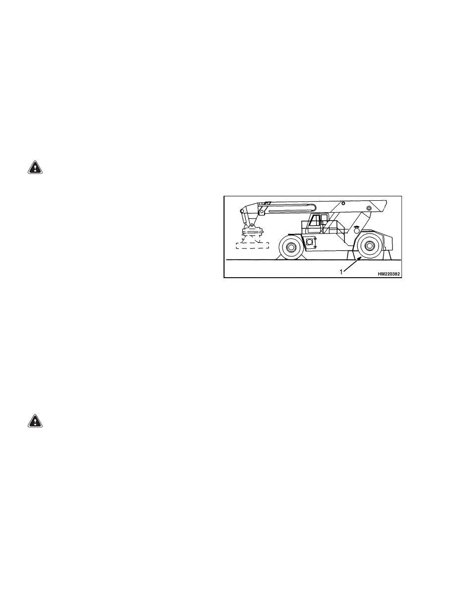
1.
Apply the parking brake.
Put blocks on both
sides (front and back) of the drive tires to prevent
movement of the ReachStacker. See Figure 2.
2.
Fully lower and retract the boom.
3.
Use a hydraulic jack to lift the steering tires. Ver-
ify that the jack has a capacity of at least 2/3 of
the total weight of the ReachStacker [approxi-
mately 54,000 kg (119,070 lb)] as shown on the
nameplate. Put the jack under the steering axle
or frame to lift the ReachStacker. Put blocks un-
der the frame as supports for the ReachStacker.
1.
STEERING TIRES
Figure 2. Put ReachStacker on Blocks
Steering Axle Assembly
NOTE: The steering axle assembly without the
wheels weighs approximately 3400 kg (7497 lb).
UP TO 1527
Remove
WARNING
The rear counterweight for the ReachStacker
®
weighs approximately 3350 kg (7387 lb). The
main counterweight weighs approximately
13,500 kg (29,762 lb). Verify the lifting devices
used during repairs can lift the weight of the
parts.
1.
Verify the wheels are set for straight travel.
Remove the counterweight(s). See the section
Frame 100 SRM 631 for the procedure to re-
move counterweights.
2.
Put the unit onto blocks so the steering axle can
be removed. Follow the instructions on How to
Lift Steer Tires in this section.
3.
It is not required, but removal of the wheels can
make it easier to remove the steer axle.
See
Wheels and Hubs, Remove and Disassemble for
the procedure to remove the wheels.
4.
Disconnect the hydraulic lines at the steering
cylinder. Install caps onto the cylinder, and put
plugs into the hydraulic lines. The caps will pre-
vent the spindles from turning when the axle is
removed from the unit.
Disconnect the brake
lines at the brake calipers. Install caps on the
calipers and put plugs into the hoses.
5.
Insert 340 mm (13.38 in.) long M30×3.5 studs
into the mounting plates.
Install a nut and
washer on each stud.
2
1600 SRM 639
Steering Axle Assembly
6.
Slide a floor jack under the steering axle. Raise
the axle by tightening the nuts on the M30×3.5
studs until the weight is removed from the pivot
pin.
WARNING
The pivot pin weighs approximately 135 kg
(295 lb). Use a lifting device that can support
the weight of the item. Verify all chains, hooks,
slings, etc. are in good condition and have the
correct capacity.
7.
Remove the plate that holds the pivot pin in the
frame. See Figure 1 and Figure 3. The end of the
pivot pin has an M30×3.5 threaded hole. Install
a threaded puller in the pivot pin. Pull the pivot
pin out of the frame.
8.
Slowly lower the axle assembly by loosening the
4 studs uniformly until it is clear of the frame
and the rubber mounts are loose, see Figure 4.
Carefully move the axle assembly from under the
ReachStacker.
Install
Before installation of the axle assembly, check the
axle housing, pivot pin, spacers, and bushings for
damage. Replace all worn or defective parts. See Fig-
ure 1 and Figure 3.
1.
Apply grease to the pivot pin bushings.
2.
Carefully move the axle assembly into position
under the ReachStacker. Align the axle assem-
bly to the frame and rubber mounts. Raise the
axle assembly into place with a jack. Install the
four M30×3.5 studs, nuts, and washers to hold
the steer axle in position. Tighten the 4 studs
uniformly until the axle is in position to install
the pivot pin.
3.
Apply grease to the pivot pin. Install the pivot
pin and spacers. Install the retainer plate and
tighten the two capscrews to 200 N•m (150 lbf ft).
Install the grease fittings.
4.
Loosen the 4 studs uniformly until the studs are
unloaded. Remove the M30×3.5 studs and the
floor jack.
5.
Remove the plugs and caps and connect the hy-
draulic lines to the steering cylinder. Turn the
steering wheel several times from one stop to the
other stop. Check for hydraulic leaks.
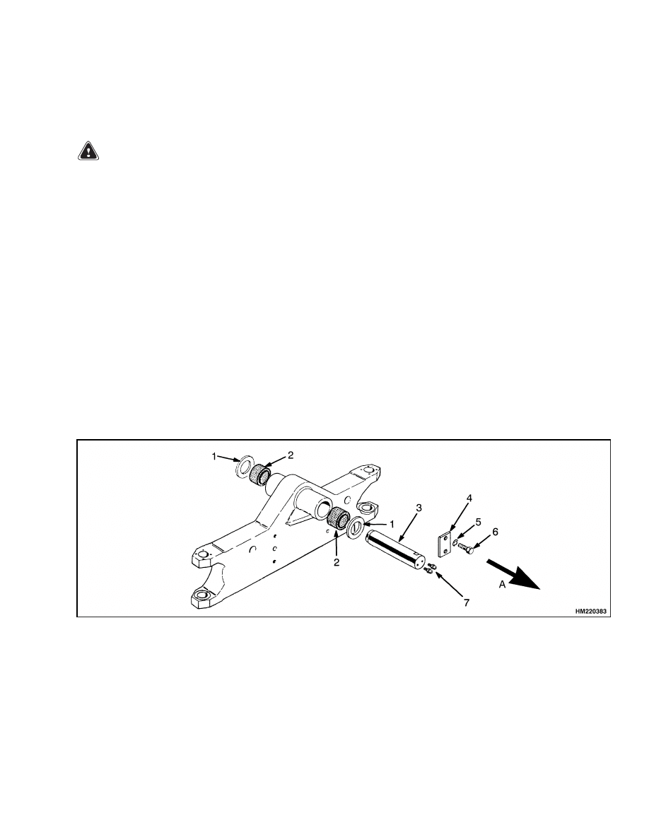
A. DRIVE DIRECTION
1.
SPACER
2.
BUSHING
3.
PIVOT PIN
4.
RETAINER PLATE
5.
WASHER
6.
CAPSCREW
7.
GREASE FITTINGS
Figure 3. Steering Axle Mounting
3
Steering Axle Assembly
1600 SRM 639
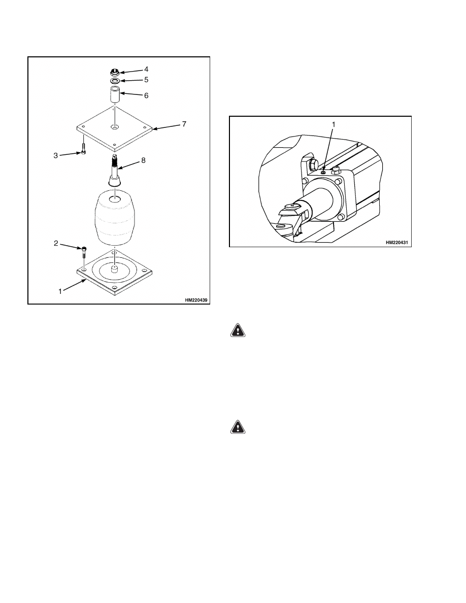
1.
FLANGE
2.
CAPSCREW
3.
RUBBER MOUNT
4.
NUT
5.
WASHER
6.
SPACER
7.
FLANGE
8.
PIN
Figure 4. Rubber Mounts
6.
Remove air from the steering system as follows:
a. Turn the steering wheel several times from
one stop to the other stop.
b. Open the special fittings on each end of the
steering cylinder to remove air from the
cylinder. See Figure 5.
c.
Repeat Step a and Step b until all of the air
is removed from the system.
7.
Remove the plugs and caps and connect the brake
lines to the calipers. Open the special fittings on
the calipers to remove air from the system.
8.
Install the wheels on the steer axle.
9.
Use a hydraulic jack to lift the steering tires.
Verify that the jack has a capacity of at least
2/3 of the total weight of the ReachStacker [ap-
proximately 54,000 kg (119,070 lb)] as shown on
the nameplate. Put the jack under the steering
axle or frame to lift the ReachStacker. Remove
the blocks from under the frame and lower the
ReachStacker.
1.
SPECIAL FITTING
Figure 5. Remove Air From Steer Cylinder
STARTING WITH 1528
Remove
WARNING
The heaviest rear counterweight (cast) weighs
approximately 7000 kg (15,432 lb). The heavi-
est main counterweight (cast) weighs approx-
imately 14,000 kg (30,865 lb), and the heaviest
main counterweight (fabricated) weighs ap-
proximately 19,300 kg (42,549 lb).
Verify the
lifting devices used during repairs can lift the
weight of the parts.
WARNING
Before removing the counterweight, put blocks
under the mast assembly so that the lift truck
cannot fall forward.
1.
Verify the wheels are set for straight travel.
Remove the counterweight(s). See the section
Frame 100 SRM 1174 for the procedure to re-
move counterweights.
2.
Put the ReachStacker on blocks so the steering
axle can be removed. Follow the instructions on
How to Lift Steer Tires in this section.
4
1600 SRM 639
Steering Axle Assembly
3.
It is not required, but removal of the wheels can
make it easier to remove the steer axle.
See
Wheels and Hubs, Remove and Disassemble for
the procedure to remove the wheels.
4.
Disconnect the hydraulic lines at the steering
cylinder. Install caps onto the cylinder, and put
plugs into the hydraulic lines. The caps will pre-
vent the spindles from turning when the axle is
removed from the ReachStacker.
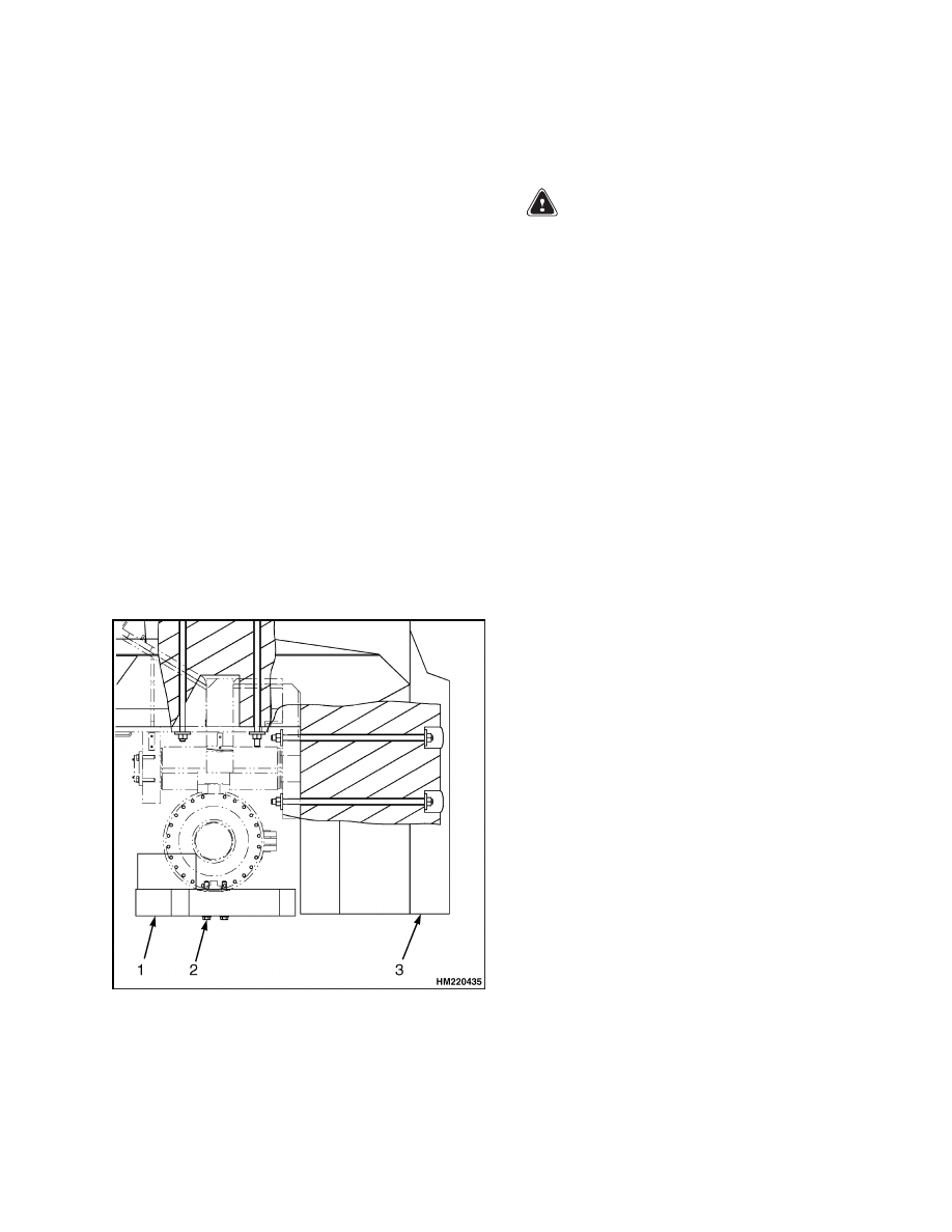
NOTE: There is a slab counterweight assembled un-
derneath the steering axle on model RS46-36CH and
RS46-33IH when a fabricated main counterweight is
attached. See Figure 6.
5.
If a slab counterweight is assembled, perform the
following steps:
a. Slide a floor jack underneath the steering
axle. Raise the floor jack so it is just support-
ing the slab counterweight.
b. Remove the four capscrews that hold the slab
counterweight underneath the steering axle.
c.
Carefully move the slab counterweight from
underneath the ReachStacker.
1.
SLAB COUNTERWEIGHT
2.
CAPSCREW
3.
MAIN COUNTERWEIGHT (FABRICATED)
Figure 6. Slab Counterweight
6.
Slide a floor jack under the steering axle. Raise
steering axle with the floor jack until the weight
is removed from the pivot pin.
WARNING
The pivot pin weighs approximately 135 kg
(295 lb). Use a lifting device that can support
the weight of the item. Verify all chains, hooks,
slings, etc. are in good condition and have the
correct capacity.
7.
Remove the plate that holds the pivot pin in the
frame. See Figure 1 and Figure 3. The end of the
pivot pin has an M30×3.5 threaded hole. Install
a threaded puller in the pivot pin. Pull the pivot
pin out of the frame.
8.
Carefully move the axle assembly from under the
ReachStacker.
Install
Before installation of the axle assembly, check the
axle housing, pivot pin, spacers, and bushings for
damage. Replace all worn or defective parts. See Fig-
ure 1 and Figure 3.
1.
Apply grease to the pivot pin bushings.
2.
Carefully move the axle assembly into position
under the ReachStacker. Align the axle assembly
to the frame. Raise the axle assembly into place
with a floor jack until the axle is in position to
install the pivot pin.
3.
Apply grease to the pivot pin. Install the pivot
pin and spacers. Install the retainer plate and
tighten the two capscrews to 200 N•m (150 lbf ft).
Install the grease fittings.
4.
Remove the floor jack.
5.
If a slab counterweight must be installed, per-
form the following steps:
a. Move the slab counterweight into position
under the steering axle. Align the slab coun-
terweight to the steering axle.
b. Install the four capscrews and tighten to
600 N•m (443 lbf ft).
6.
Remove the plugs and caps and connect the hy-
draulic lines to the steering cylinder. Turn the
steering wheel several times from one stop to the
other stop. Check for hydraulic leaks.
5
Wheels and Hubs
1600 SRM 639
7.
Remove air from the steering system as follows:
a. Turn the steering wheel several times from
one stop to the other stop.
b. Open the special fittings on each end of the
steering cylinder to remove air from the
cylinder. See Figure 5.
c.
Repeat Step a and Step b until all of the air
is removed from the system.
8.
Install the wheels on the steer axle. See Wheels
and Hubs, Assemble and Install for the proce-
dure to install the wheels.
9.
Verify the wheels are set in a straight line of
travel. Install the counterweights. See the sec-
tion Frame 100 SRM 1174 for the procedure to
install counterweights.
10. Use a hydraulic jack to lift the steering tires. Ver-
ify the jack has a capacity of at least 2/3 of the
total weight of the ReachStacker as shown on
the nameplate. Put the jack under the steering
axle or frame to lift the ReachStacker. Remove
the blocks from under the frame and lower the
ReachStacker.
Wheels and Hubs
REMOVE AND DISASSEMBLE
WARNING
Completely remove the air from the tires be-
fore removing them from the ReachStacker
®
.
Air pressure in the tires can cause the tire and
rim parts to explode, which can cause serious
injury or death.
WARNING
The steer wheel and tire assembly weighs ap-
proximately 750 kg (1650 lb). Use the following
procedure to remove the tire and wheel assem-
bly from the steer axle. Use a lifting device if
the tire and wheel assembly must be lifted.
1.
Put the axle on the blocks so the tires are raised
from the floor. Completely remove the air from
the tires. Remove the wheels.
2.
Remove the capscrews that hold the brake
caliper to the spindle. See Figure 7.
3.
Remove the wheel hub cover plate. Loosen the
three setscrews on the adjustment nut. Remove
the adjustment nut. Remove the spacer.
WARNING
To avoid personal injury, use a hoist to lift com-
ponents that weigh more than 23 kg (50 lb).
Verify the hoist or lift device is strong enough
to support the weight of the item. Verify all
chains, hooks, slings, etc. are in good condition
and have the correct capacity.
4.
Support the hub with a hoist or a lifting device.
Pull the hub assembly away from the spindle.
Remove the retainer ring and the inner bearing
ring from the spindle. Remove the oil seal from
the retainer ring.
5.
If wheel bearings are damaged, use a brass drift
to remove the bearing cups from the hub.
CLEAN
WARNING
Cleaning solvents can be flammable and toxic
and can cause skin irritation.
When using
cleaning solvents, always follow the solvent
manufacturer’s safety procedures.
1.
Clean all moving parts with solvent. Verify the
bearings are clean.
CAUTION
Do not wash parts with steam or hot water
since it will be difficult to remove all of the
surface moisture.
2.
Dry all component parts with an air jet or soft
cloth to avoid damage to the surface from abra-
sive particles.
3.
Check that all surfaces are covered with a thin
film of oil to protect them against corrosion.
6
1600 SRM 639
Wheels and Hubs
1.
CAPSCREW
2.
WASHER
3.
WHEEL HUB COVER
4.
ADJUSTMENT NUT
5.
SPACER
6.
OUTER BEARING
7.
WHEEL HUB
8.
INNER BEARING
9.
O-RING
10. RETAINER RING
11. OIL SEAL
12. STUD
13. WASHER
14. WASHER
15. NUT
Figure 7. Hub Assembly
ASSEMBLE AND INSTALL
If new wheel bearings are installed, use a press to
install the new bearing cups in the wheel hub. Verify
the bearings are filled with grease. See Figure 3.
CAUTION
Do not damage the seals during installation.
1.
Install the oil seal rings in the retainer ring.
Press the seal ring into the retainer ring.
2.
Install the inner bearing ring in the cup in the
wheel hub.
Verify the bearing is filled with
grease.
3.
Install the retaining ring in the wheel hub. Use a
soft hammer to gently seat the retainer ring fully
in the hub.
4.
Carefully slide the hub onto the spindle.
5.
Install the outer bearing on the spindle. Install
the spacer.
6.
Tighten the adjustment nut until the hub begins
to rotate.
7.
Wrap a rope tightly around the hub several
times.
Pull on the rope with a spring scale.
Tighten the adjusting nut until the hub rotating
torque is 93.2 to 127.5 N•m (68.8 to 94.0 lbf ft).
8.
Tighten the setscrews on the adjustment nut.
9.
Fill the area between the two bearings and be-
tween the bearing and the cover with grease.
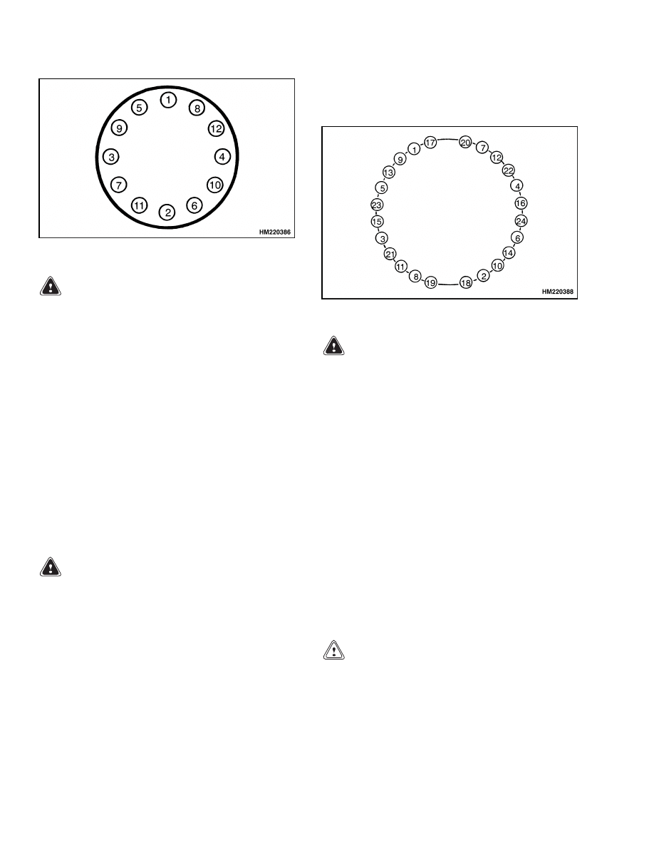
10. Spread a seal compound on the inside of the
wheel hub cover. Place the cover on the hub.
Tighten the capscrews to 25 N•m (18.5 lbf ft)
in the sequence shown in Figure 8 and tighten
again to 45.1 N•m (33 lbf ft) in the same se-
quence.
7
Spindles, Bearings, and Tie Rods
1600 SRM 639
Figure 8. Wheel Hub Cover
WARNING
Add air pressure to the tires only in a safety
cage. Inspect the safety cage for damage be-
fore use.
When air pressure is added, use a
chuck that fastens onto the valve stem of the
inner tube. Verify there is enough hose to per-
mit the operator to stand away from the safety
cage when air pressure is added to the tire. Do
not sit or stand by the safety cage.
11. Inflate the tire (check truck data plate for correct
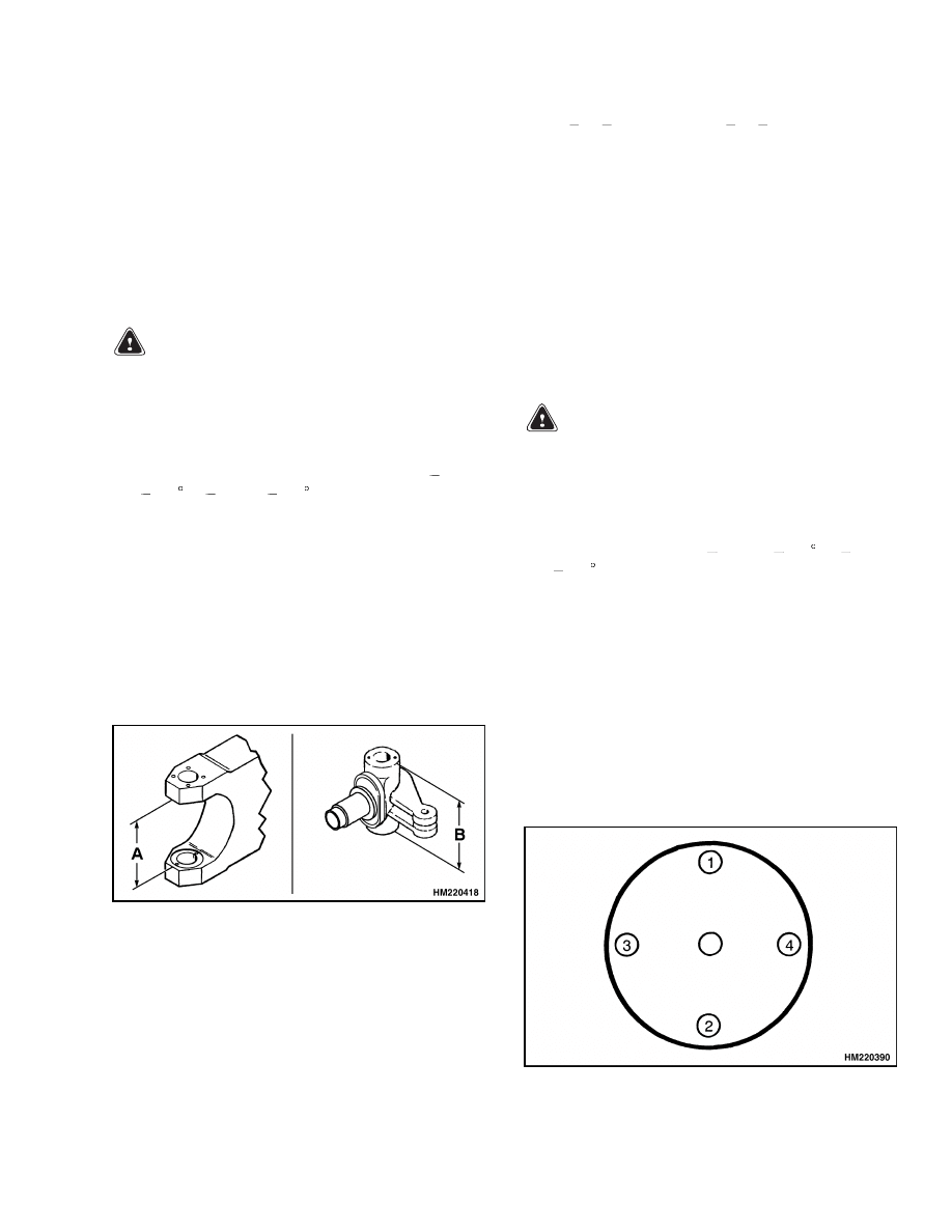
inflate pressure). Mount the wheel and tighten
the wheel nuts to 70 N•m (52 lbf ft) in the se-
quence shown in Figure 9.
Check for correct
alignment of wheel parts and inside wheel to hub
alignment after tightening nuts 1 through 4. Fi-
nally, tighten the wheel nuts to 128 to 147 N•m
(94 to 108 lbf ft).
Figure 9. Wheel Nuts
WARNING
Check all wheel nuts after 2 to 5 hours of oper-
ation when a new ReachStacker begins opera-
tion and on all ReachStackers when the wheels
have been removed and installed. Tighten the
nuts in a cross pattern to the correct torque
value. When the nuts stay tight for 8 hours,
the interval for checking the torque can be ex-
tended to 250 hours.
12. Repeat the procedure for the other wheel.
Spindles, Bearings, and Tie Rods
REMOVE
WARNING
Completely remove the air from the tires be-
fore removing them from the ReachStacker
®
.
Air pressure in the tires can cause the tire and
rim parts to explode, which can cause serious
injury or death.
Put the ReachStacker onto blocks so the tires are
raised from the floor. Completely remove the air from
the tires. See the section for the procedure for remov-
ing the wheel and tire assembly. Remove the wheel
and tire assembly from the steering axle hub. Re-
move the hub from the steering axle spindle. See Fig-
ure 3.
1.
Remove the split pins and lock nuts on the tie
rods.
2.
With a puller, remove the pins from the tie rods.
3.
Remove the snap rings from the tie rods.
4.
Remove the spherical bearings from the tie rods.
5.
Remove the upper and lower cover plates from
the axle housing.
CAUTION
To avoid personal injury, use a hoist when lift-
ing components that weigh more than 23 kg
(50 lb). Verify the hoist or lift device is strong
enough to support the weight of the item. Ver-
ify all chains, hooks, slings, etc. are in good
condition and are of correct capacity.
6.
Support the spindle with a hoist or lifting device.
Remove the kingpin with a hydraulic press.
8
1600 SRM 639
Spindles, Bearings, and Tie Rods
7.
Remove the spindle with support from a lifting
device or a hoist. Save the thrust washers and
bearings.
8.
Remove the kingpin bushings from the axle hous-
ing.
INSTALL
1.
Install the lower cover plates for the spindle on
the axle housing. See Figure 3.
WARNING
Material that is cooled to very low tempera-
tures can cause injury on contact. Wear protec-
tive clothing including insulated gloves, safety
glasses, and face shields. Handle liquid nitro-
gen and cooled parts carefully.
2.
Cool the upper and lower bushings to
200 to
230 C ( 328 to
382 F) in liquid nitrogen. In-
stall the lower bushing in the axle housing until
it contacts the lower cover.
3.
Install shims with a total thickness of 1.5 mm
inside the lower bushing.
4.
Install the groove pins in the axle housing.
5.
Install the lower and the upper thrust washers
on the axle housing. Measure the distance be-
tween the thrust washers on the axle housing.
See Figure 10. This is dimension A.
Figure 10. Dimensions A and B
6.
Install the pins on the spindle. Measure the dis-
tance across the spindle. See Figure 10. This is
dimension B.
7.
Subtract the measurement in Step 6 from the
measurement in Step 5.
Select shims/thrust
washer so the thickness is 0.1 mm (0.004 in.)
less than the clearance.
S = A
B
0.1 mm (S = A
B
0.004 in.)
where
S = shims/thrust washer
A = distance across the axle housing
B = distance across the spindle
8.
Install the shims/thrust washer and upper
thrust washer on the spindle and the upper
thrust washer in the axle housing.
9.
Support the spindle with a hoist or lifting de-
vice and install it in the axle housing. Lubricate
the surfaces with molybdenum disulfide grease
to ease installation.
WARNING
Material that is cooled to very low tempera-
tures can cause injury on contact. Wear protec-
tive clothing including insulated gloves, safety
glasses, and face shields. Handle liquid nitro-
gen and cooled parts carefully.
10. Cool the kingpin to
200 to
230 C ( 328 to
382 F). The top end of the kingpin is larger than
the bottom end. Install the kingpin in the axle
housing from the top of the housing until it con-
tacts the shims installed in Step 3.
11. Remove the lower cover and remove the shims.
12. Spread a sealant compound on the underside
of the cover plates.
Install the cover plates.
Tighten the capscrews to 75 N•m (55 lbf ft) in
the sequence shown in Figure 11 and tighten
to 150 N•m (111 lbf ft) in the same sequence.
Tighten a final time to 383 N•m (283 lbf ft) in
the same sequence.
Figure 11. Kingpin Cover Plate
9
Steering Cylinder
1600 SRM 639
13. Fill the upper and lower bushing areas with
grease through the grease fittings.
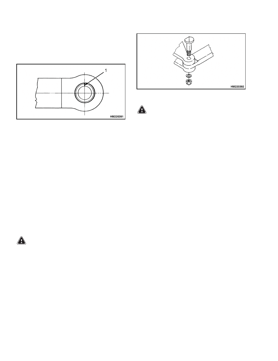
14. Install the spherical bearings in the tie rods.
Align bearings as shown in Figure 12.
1.
NOTCH
Figure 12. Tie Rod Bearing
15. Install the snap rings in the tie rod. Install the
bearing thrust washers above and below the snap
rings.
16. Connect the tie rods. See Figure 13. Align the tie
rods with the spindle and steering cylinder ends.
Grease the pin. Install the pin and washers and
tighten the lock nuts. Install the split pins.
Figure 13. Spindle and Tie Rod Connection
WARNING
Add air pressure to the tires only in a safety
cage. Inspect the safety cage for damage be-
fore use.
When air pressure is added, use a
chuck that fastens onto the valve stem of the
inner tube. Verify there is enough hose to per-
mit the operator to stand away from the safety
cage when air pressure is added to the tire. Do
not sit or stand by the safety cage.
17. Inflate the tires to 1000 kPa (145 psi) (check
truck data plate). Mount the wheels and tighten
the wheel nuts to 140 N•m (103 lbf ft).
18. See the section for the procedure for installing
the wheel and hub assembly.
Steering Cylinder
UP TO 1532
Remove and Disassemble
WARNING
To avoid personal injury, use a hoist to lift com-
ponents that weigh more than 23 kg (50 lb).
Make sure the hoist or lift device is strong
enough to support the weight of the item.
Make sure all chains, hooks, slings, etc. are in
good condition and are of correct capacity.
1.
Disconnect the hydraulic lines at the steering
cylinder. See Figure 14. Mark the locations of
the hydraulic lines to ensure correct assembly.
Install caps in the fittings on the cylinders and
put caps on the hydraulic lines.
2.
Disconnect the tie rods. Remove the split pins,
lock nuts, and washers from the tie rod pins. Re-
move the pins.
NOTE: The steer cylinder weighs approximately
265 kg (584 lb).
3.
Remove the capscrews that fasten the cylinder to
the axle frame. Remove the steering cylinder.
4.
Place a drain pan under the end of the steering
cylinder. Remove the cap for the hydraulic fitting
from each end cap. Push the rod toward the end
of the shell that is over the drain pan. Oil will
drain from the cylinder. Repeat the procedure for
the other end.
10
1600 SRM 639
Steering Cylinder
1.
SHELL
2.
PISTON SEALS
3.
ROD
4.
WIPER RING
5.
CAPSCREW
6.
CAPSCREW
7.
END FLANGE
8.
GUIDE
9.
O-RING
10. JOINT
11. GUIDE ASSEMBLY
12. PISTON FLANGE
13. BACKUP RING
14. O-RING
Figure 14. Steering Cylinder
5.
Carefully remove one end flange from the shell.
Carefully pull the cylinder rod and piston from
the shell. Keep the cylinder rod aligned in the
center of the shell during removal so the parts
are not damaged. Remove the piston flange from
the rod. Remove the other end flange and piston
flange from the shell. Remove all seals, wipers,
guides, and O-rings.
Clean and Inspect
WARNING
Cleaning solvents can be flammable and toxic
and can cause skin irritation.
When using
cleaning solvents, always follow the solvent
manufacturer’s safety procedures.
Clean all parts in solvent. Inspect the piston rod
for grooves or damage. Remove small scratches with
fine emery cloth. Inspect the cylinder bore for dam-
age. Inspect the mounts for cracks.
Assemble and Install
Before installation of the steering cylinder, check the
shell, joint and guide assemblies, piston flange, rod,
and seals for damage. Replace all worn or damaged
parts. See Figure 14.
1.
Put the O-rings and seals into warm hydraulic
oil.
CAUTION
Do not damage the O-rings, seals, or wipers
during installation.
2.
Lubricate the guide rings and joints with O-ring
lubricant and install them into the guide assem-
blies. Lubricate the piston seals and install them
onto the piston. Install one piston flange and end
flange onto the cylinder rod.
3.
Carefully slide the cylinder rod and piston into
the shell. Keep the cylinder rod aligned in the
center of the shell during installation so the
parts are not damaged. Carefully slide the pis-
ton flange into the shell. Carefully install the
other piston flange onto the rod and shell. Put
caps on the hydraulic fittings of the end caps.
4.
Install the cylinder onto the axle frame. Install
the spacers between the cylinder mounts and the
axle frame. Tighten the capscrews to 1200 to
1400 N•m (885 to 1033 lbf ft).
5.
Install the tie rods.
6.
Remove the caps and connect the hydraulic lines
to the steering cylinder.
STARTING WITH 1533
Remove and Disassemble
WARNING
To avoid personal injury, use a hoist to lift com-
ponents that weigh more than 23 kg (50 lb).
Make sure the hoist or lift device is strong
enough to support the weight of the item.
Make sure all chains, hooks, slings, etc. are in
good condition and are of correct capacity.
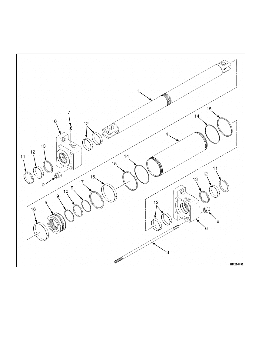
1.
Disconnect the hydraulic lines at the steering
cylinder. See Figure 15. Mark the locations of
11
Steering Cylinder
1600 SRM 639
the hydraulic lines to ensure correct assembly.
Install caps in the fittings on the cylinders and
put caps on the hydraulic lines.
2.
Disconnect the tie rods. Remove the split pins,
lock nuts, and washers from the tie rod pins. Re-
move the pins.
1.
CYLINDER ROD
2.
NUT
3.
ANCHOR ROD
4.
SHELL
5.
PISTON
6.
CYLINDER FLANGE
7.
CAPSCREW
8.
WASHER
9.
WASHER
10. O-RING
11. RING
12. ROD RING
13. ROD SEAL
14. O-RING
15. RING
16. PISTON RING
17. PISTON SEAL
Figure 15. Steering Cylinder
12
1600 SRM 639
Steering Cylinder
NOTE: The steer cylinder weighs approximately
265 kg (584 lb).
3.
Remove the capscrews that fasten the cylinder to
the axle frame. Remove the steering cylinder.
4.
Place a drain pan under the end of the steering
cylinder. Remove the cap for the hydraulic fitting
from each end cap. Push the rod toward the end
of the shell that is over the drain pan. Oil will
drain from the cylinder. Repeat the procedure for
the other end.
5.
Remove from one side, four nuts from the four
anchor rods, and remove the anchor rods from
the cylinder flanges.
NOTE: Keep the cylinder rod aligned in the center of
the shell during removal so the parts are not dam-
aged.
6.
Carefully remove one cylinder flange from the
shell and cylinder rod. Carefully pull the cylin-
der rod, piston, and second cylinder flange from
the shell.
Remove the second cylinder flange
from the cylinder rod. Remove all seals, rings,
and O-rings. If necessary, remove the piston from
the cylinder rod and clean the thread from the
piston and cylinder rod.
Clean and Inspect
WARNING
Cleaning solvents can be flammable and toxic
and can cause skin irritation.
When using
cleaning solvents, always follow the solvent
manufacturer’s safety procedures.
Clean all parts in solvent. Inspect the piston rod
for grooves or damage. Remove small scratches with
fine emery cloth. Inspect the cylinder bore for dam-
age. Inspect the mounts for cracks.
Assemble and Install
Before installation of the steering cylinder, check the
shell, joint and guide assemblies, piston flange, rod,
and seals for damage. Replace all worn or damaged
parts. See Figure 15.
1.
Put the O-rings and seals into warm hydraulic
oil.
CAUTION
Do not damage the O-rings, seals, or wipers
during installation.
2.
Lubricate the seals, rings, and O-rings with
O-ring lubricant and install.
3.
If necessary, apply adhesive to the thread of the
piston and cylinder rod. Install the piston onto
the cylinder rod.
4.
Install one cylinder flange with rings and seal
onto the cylinder rod.
NOTE: Keep the cylinder rod aligned in the center
of the shell during installation so the parts are not
damaged.
5.
Carefully slide the cylinder rod, piston, and cylin-
der flange into the shell. Carefully install the
second cylinder flange onto the cylinder rod and
shell. Install the four anchor rods through the
two cylinder flanges with the nuts. Put caps on
the hydraulic fittings of the end caps.
6.
Install the cylinder onto the axle frame. Install
the spacers between the cylinder mounts and the
axle frame. Tighten the capscrews to 1200 to
1400 N•m (885 to 1033 lbf ft).
7.
Install the tie rods.
8.
Remove the caps and connect the hydraulic lines
to the steering cylinder.
13

Troubleshooting
1600 SRM 639
Torque Specifications
Hub Cover Capscrews
45.1 N•m (33 lbf ft)
Wheel Hub Capscrews
333.5 N•m (246 lbf ft)
Steering Wheel Nuts
128 to 147 N•m (94 to 108 lbf ft)
Spindle Plate Capscrews
383 N•m (283 lbf ft)
Cylinder Mount Capscrews
1200 to 1400 N•m (885 to 1033 lbf ft)
Slab Counterweight Capscrews
600 N•m (443 lbf ft)
Troubleshooting
PROBLEM
POSSIBLE CAUSE
PROCEDURE OR ACTION
The steering wheels do not
move
when
the
steering
wheel is turned.
The oil level is low or there is no oil
in the tank.
Fill tank. Check for leaks.
The steering control unit is dam-
aged.
Repair or install new control unit.
No oil flow from the steering control
unit to the steering cylinder.
Repair or install new components.
Check for leaks.
Slow or difficult steering.
Relief valve for the steering system
needs adjustment.
Adjust or install new relief valve.
Low oil pressure from the hydraulic
pump.
Check for restrictions.
Seal in the steering cylinder has a
leak.
Install new seal.
Steering control unit is worn or has
damage.
Repair or install new control unit.
Steering wheel turns the
tires in the wrong direction.
The hydraulic lines are not con-
nected correctly at the steering
cylinder or at the steering control
unit.
Connect lines properly. Remove air
from the system.
Steering
function
contin-
ues after the steering wheel
stops.
The steering control unit was assem-
bled wrong or has damage.
Repair or install new control unit.
14

1600 SRM 639
Troubleshooting
PROBLEM
POSSIBLE CAUSE
PROCEDURE OR ACTION
There is air in the steering
system.
The oil level in the tank is low.
Add
hydraulic
oil
as
necessary.
Check for leaks.
Air was not removed after repair to
the hydraulic or steering system.
Remove air from the system.
The hydraulic pump has an air leak
at the inlet.
Repair system. Remove air from the
system.
15

NOTES
____________________________________________________________
____________________________________________________________
____________________________________________________________
____________________________________________________________
____________________________________________________________
____________________________________________________________
____________________________________________________________
____________________________________________________________
____________________________________________________________
____________________________________________________________
____________________________________________________________
____________________________________________________________
____________________________________________________________
____________________________________________________________
____________________________________________________________
____________________________________________________________
____________________________________________________________
____________________________________________________________
____________________________________________________________
____________________________________________________________
16


TECHNICAL PUBLICATIONS
1600 SRM 639
3/05 (4/98) Printed in United Kingdom
Document Outline
- toc
Wyszukiwarka
Podobne podstrony:
1459370 1600SRM0720 (07 2005) UK EN
1598459 1900SRM1213 (03 2005) UK EN
897956 1900SRM0642 (03 2005) UK EN
897986 1600SRM0658 (03 1997) UK EN
897963 4500SRM0649 (03 2005) UK EN
1565582 1600SRM1114 (04 2005) UK EN
1573930 0600SRM1172 (03 2005) UK EN
1453608 1600SRM0687 (03 2002) UK EN
1586985 2200SRM1178 (03 2005) UK EN
897345 1400SRM0413 (03 2005) UK EN
1531815 1800SRM1040 (03 2005) UK EN
1580512 1600SRM1133 (05 2005) UK EN
899782 2000SRM0077 (03 2005) UK EN
897983 1600SRM0655 (03 2002) UK EN
1554628 1600SRM1075 (03 2004) UK EN
897875 8000SRM0616 (03 2005) UK EN
1482617 1600SRM0797 (03 2000) UK EN
więcej podobnych podstron