DRIVE AXLE, SPEED
REDUCER, AND
DIFFERENTIAL
E3.50-5.50XL (E70-120XL, E70-120XL
3
) [C098];
E3.50-5.50XL, E4.50XLS
(E70-120Z, E100ZS) [D098]
PART NO. 897345
1400 SRM 413

SAFETY PRECAUTIONS
MAINTENANCE AND REPAIR
• When lifting parts or assemblies, make sure all slings, chains, or cables are correctly
fastened, and that the load being lifted is balanced. Make sure the crane, cables, and
chains have the capacity to support the weight of the load.
• Do not lift heavy parts by hand, use a lifting mechanism.
• Wear safety glasses.
• DISCONNECT THE BATTERY CONNECTOR before doing any maintenance or repair
on electric lift trucks. Disconnect the battery ground cable on internal combustion lift
trucks.
• Always use correct blocks to prevent the unit from rolling or falling. See HOW TO PUT
THE LIFT TRUCK ON BLOCKS in the Operating Manual or the Periodic Mainte-
nance section.
• Keep the unit clean and the working area clean and orderly.
• Use the correct tools for the job.
• Keep the tools clean and in good condition.
• Always use HYSTER APPROVED parts when making repairs. Replacement parts
must meet or exceed the specifications of the original equipment manufacturer.
• Make sure all nuts, bolts, snap rings, and other fastening devices are removed before
using force to remove parts.
• Always fasten a DO NOT OPERATE tag to the controls of the unit when making repairs,
or if the unit needs repairs.
• Be sure to follow the WARNING and CAUTION notes in the instructions.
• Gasoline, Liquid Petroleum Gas (LPG), Compressed Natural Gas (CNG), and Diesel fuel
are flammable. Be sure to follow the necessary safety precautions when handling these
fuels and when working on these fuel systems.
• Batteries generate flammable gas when they are being charged. Keep fire and sparks
away from the area. Make sure the area is well ventilated.
NOTE: The following symbols and words indicate safety information in this
manual:
WARNING
Indicates a condition that can cause immediate death or injury!
CAUTION
Indicates a condition that can cause property damage!
Drive Axle, Speed Reducer, and Differential
Table of Contents
TABLE OF CONTENTS
General ...............................................................................................................................................................
Description .........................................................................................................................................................
Drive Axle, Speed Reducer, and Differential Repair........................................................................................
Remove ...........................................................................................................................................................
General.......................................................................................................................................................
Traction Motor, Speed Reducer, and Differential ....................................................................................
Motor, Speed Reducer, and Differential, Remove................................................................................
Disassemble ...................................................................................................................................................
Speed Reducer ...........................................................................................................................................
Differential ................................................................................................................................................
Clean ..............................................................................................................................................................
Inspect ............................................................................................................................................................
Assemble ........................................................................................................................................................
Speed Reducer ...........................................................................................................................................
Input Gear, Install ................................................................................................................................
New Pinion, Install ...............................................................................................................................
Differential ................................................................................................................................................
Drive Axle Housing........................................................................................................................................
Remove.......................................................................................................................................................
Clean ..........................................................................................................................................................
Inspect........................................................................................................................................................
Assemble ....................................................................................................................................................
Troubleshooting..................................................................................................................................................
This section is for the following models:
E3.50-5.50XL (E70-120XL, E70-120XL
3
) [C098];
E3.50-5.50XL, E4.50XLS (E70-120Z, E100ZS) [D098]
©2005 HYSTER COMPANY
i

"THE
QUALITY
KEEPERS"
HYSTER
APPROVED
PARTS
1400 SRM 413
Description
General
This section has the description and repair procedures for the differential, speed reducer, drive axle, wheel
bearings, and mounts for the axle housing.
Description
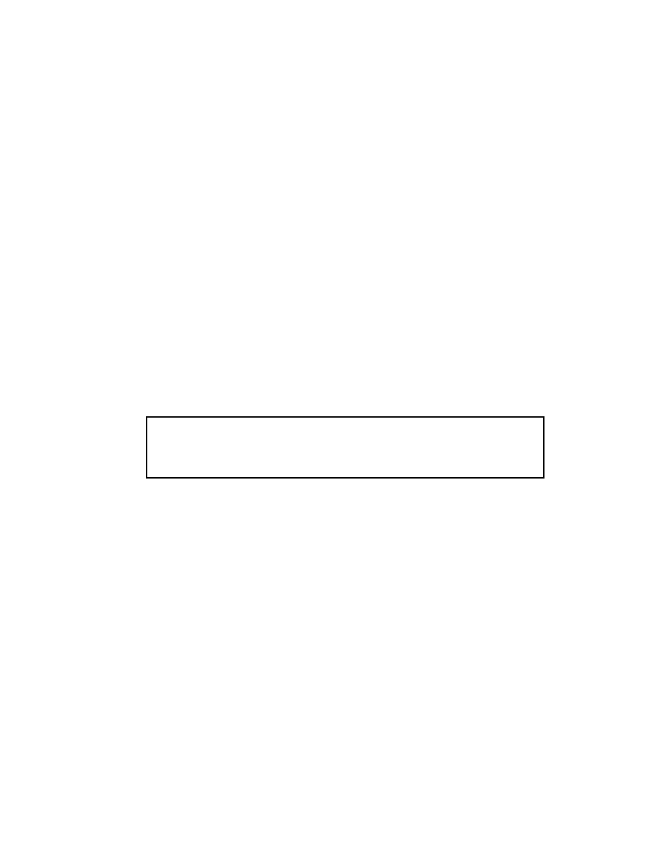
The drive axle assembly is fastened to the frame of
the lift truck by separate mounts. See Figure 1. The
drive axle assembly can rotate in the mounts. The
outer ends of the axle housings are the spindles for
the wheel bearings. The wheel bearings are tapered
roller bearings with the cups pressed into the hubs.
1.
AXLE HOUSING
2.
AXLE MOUNT
3.
BRAKE ASSEMBLY
4.
BRAKE DRUM
5.
SEAL
6.
BEARING CONE
7.
BEARING CUP
8.
HUB
9.
ADJUSTMENT NUT
10. LOCKWASHER
11. LOCK NUT
12. AXLE SHAFT
13. TIRE AND WHEEL
14. MOUNTING PIN
15. DOWEL PIN
Figure 1. Drive Axle Assembly
1

Drive Axle, Speed Reducer, and Differential Repair
1400 SRM 413
The nut on the end of the axle housing adjusts and
holds the wheel bearings. The axle shafts are fas-
tened to the hubs by capscrews and two dowel pins.
The back plate and brake assembly are fastened to
the axle mounts. The axle housing also has bearing
journals for the upright.
The outer wheel bearing is lubricated by gear oil from
the differential housing. The inner wheel bearing is
lubricated by wheel bearing grease.
Drive Axle, Speed Reducer, and Differential Repair
REMOVE
General
1.
Remove mast assembly as described for lift truck
models E3.50-5.50XL (E70-120XL) (C098) in sec-
tion Vista
®
Masts, Description and Repairs
For Lift Trucks with 3,500 to 6,000 kg (7,000
to 12,000 lb) Capacities 4000 SRM 340 or for
models E3.50-5.50XL (E70-120XL
3
) (C098) and
E3.50-5.50XL, E4.50XLS (E70-120Z, E100ZS)
(D098) in section Masts, Description and Re-
pairs 4000 SRM 736 for your specific lift truck.
2.
Remove battery as described in the section Peri-
odic Maintenance 8000 SRM 291 for lift truck
models E3.50-5.50XL (E70-120XL) (C098), Peri-
odic Maintenance 8000 SRM 915 for lift truck
models
E3.50-5.50XL
(E70-120XL
3
)
(C098),
or Periodic Maintenance 8000 SRM 1201
for lift truck models E3.50-5.50XL, E4.50XLS
(E70-120Z, E100ZS) (D098) under How to
Change Battery.
3.
Raise lift truck and put blocks under all four
wheels.
Drain oil from differential housing.
See the section Periodic Maintenance 8000
SRM 291 for lift truck models E3.50-5.50XL
(E70-120XL) (C098), Periodic Maintenance
8000 SRM 915 for lift truck models E3.50-5.50XL
(E70-120XL
3
) (C098), or Periodic Mainte-
nance 8000 SRM 1201 for lift truck models
E3.50-5.50XL, E4.50XLS (E70-120Z, E100ZS)
(D098) under How to Put Lift Truck on
Blocks.
WARNING
The lift truck must be put on blocks for some
types of maintenance and repair. The removal
of the following assemblies will cause large
changes in the center of gravity: attachment,
mast, drive axle, battery, and counterweight.
When the lift truck is put on blocks, put addi-
tional blocks in the following positions:
a. Before removing the mast and drive axle,
put blocks under the counterweight so the
lift truck cannot tip backward.
b. Before removing the battery or counter-
weight, put blocks under the mast assem-
bly so the lift truck cannot tip forward.
Put the lift truck on blocks only if the surface
is solid, even, and level. Make sure that any
blocks used to support the lift truck are solid,
one-piece units.
4.
Remove capscrews that hold axle shafts to hubs.
There are two holes with threads in the flange of
the axle shaft. Put capscrews (M16×2) in these
holes to push axle shaft from hub. Or, hit end
of axle shaft with a soft hammer. Remove axle
shaft.
NOTE: For lift truck models E3.50-5.50XL (E70-
120XL, E70-120XL
3
) (C098) perform Step 5 and
For lift truck models E3.50-5.50XL,
E4.50XLS (E70-120Z, E100ZS) (D098), go to Step 7.
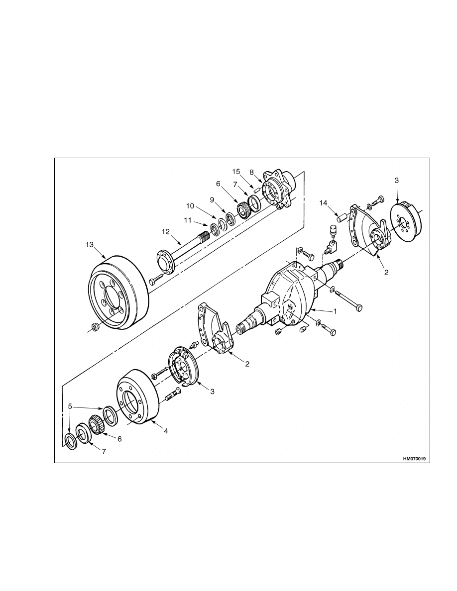
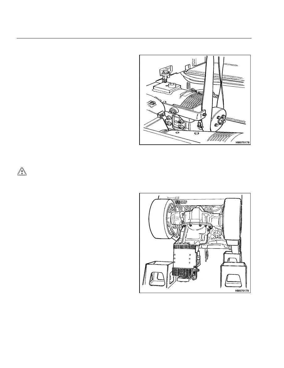
5.
Hold seat in down position. Disconnect adjust-
ment rod for seat brake at top connection. Lift
rod out of brake lever. See Figure 2.
2
1400 SRM 413
Drive Axle, Speed Reducer, and Differential Repair
Figure 2. Seat Brake Linkage, E3.50-5.50XL
(E70-120XL, E70-120XL
3
) (C098) Models
6.
Remove adjustment spring.
First, loosen two
jamnuts at bottom of rod. Then, turn top jam
nut up rod so spring will be locked in compressed
position.
Disconnect spring and rod assembly
from seat lever and lift assembly from bracket on
speed reducer housing.
7.
Remove clamp for main hoist hose from top of
speed reducer housing. Remove clamp for tilt
hoses from top of housing.
Traction Motor, Speed Reducer, and
Differential
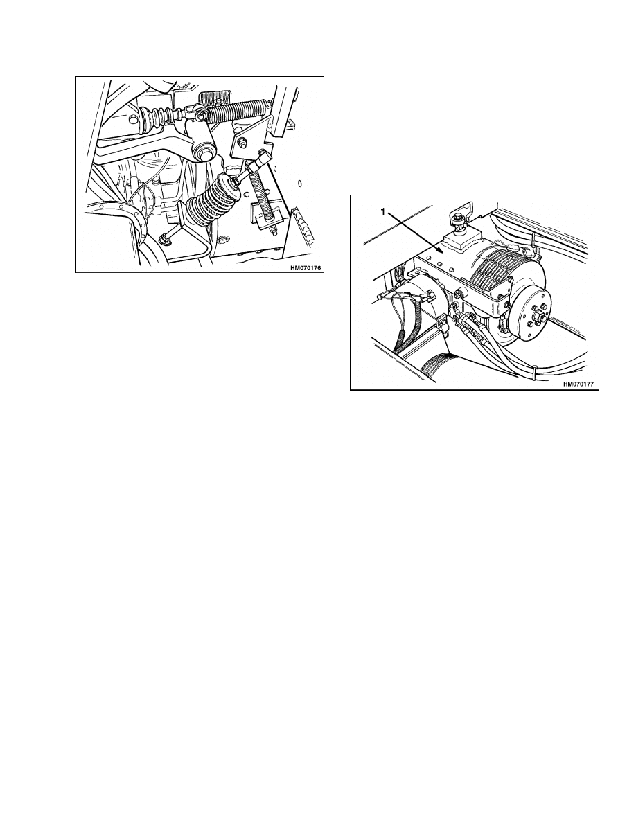
1.
Mark traction motor electrical leads for identi-
fication and remove leads from motor. See Fig-
ure 3.
2.
Continue the removal procedure as described in
Motor, Speed Reducer, and Differential, Remove.
NOTE: TRACTION MOTOR USED ON E3.50-5.50XL
(E70-120XL, E70-120XL
3
) (C098) MODELS SHOWN.
1.
TRACTION MOTOR
Figure 3. Disconnect Traction Motor
3
Drive Axle, Speed Reducer, and Differential Repair
1400 SRM 413
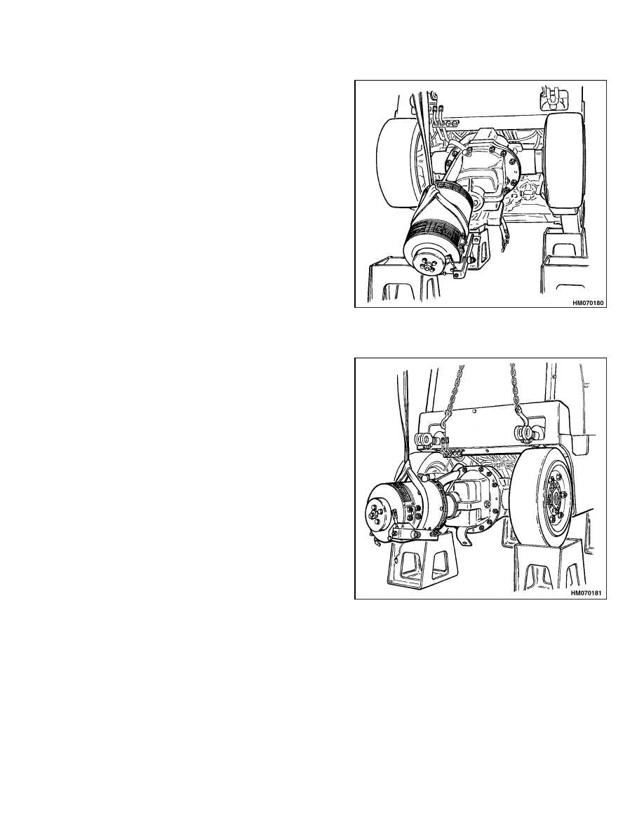
Motor, Speed Reducer, and Differential, Remove
STEP 1.
Put sling around traction motor for support. Attach
sling to lifting device. Remove capscrew that fastens
motor to lift truck frame.
Slowly lower motor to
ground.
NOTE: Traction motor used on E3.50-5.50XL (E70-
120XL, E70-120XL
3
) (C098) models shown.
CAUTION
Make sure that the steer wheels do not come off the wheel blocks while raising the front of the lift
truck.
STEP 2.
Attach lifting chains through two access holes in
front of cowl plate and carefully raise lift truck off
wheel blocks at drive wheels. Use an overhead crane
with enough capacity to raise lift truck.
NOTE: Traction motor used on E3.50-5.50XL (E70-
120XL, E70-120XL
3
) (C098) models shown.
4
1400 SRM 413
Drive Axle, Speed Reducer, and Differential Repair
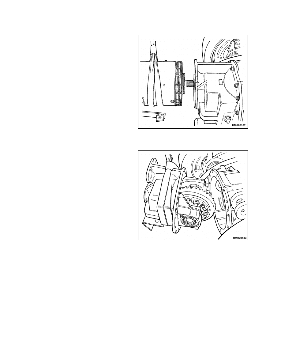
STEP 3.
Raise lift truck until traction motor is suspended ver-
tically under drive axle. Use sling around traction
motor. Pull sling toward front of lift truck as lift truck
drive wheels are lowered onto wheel blocks.
NOTE: Traction motor used on E3.50-5.50XL (E70-
120XL, E70-120XL
3
) (C098) models shown.
STEP 4.
Pivot traction motor upward to approximately 15 de-
grees above horizontal. Put blocks under differential
for support.
NOTE: Traction motor used on E3.50-5.50XL (E70-
120XL, E70-120XL
3
) (C098) models shown.
5
Drive Axle, Speed Reducer, and Differential Repair
1400 SRM 413
STEP 5.
Keep sling and lifting device attached to motor for
support and remove all capscrews that fasten motor
to speed reducer.
Carefully remove traction motor from speed reducer
and put motor on a suitable work or storage area.
See the section DC Motor Maintenance 620 SRM
294 for lift truck models E3.50-5.50XL (E70-120XL,
E70-120XL
3
) (C098) or AC Motor Repair 620 SRM
1098 for lift truck models E3.50-5.50XL, E4.50XLS
(E70-120Z, E100ZS) (D098) for repair procedures for
traction motor if required.
NOTE: Traction motor used on E3.50-5.50XL (E70-
120XL, E70-120XL
3
) (C098) models shown.
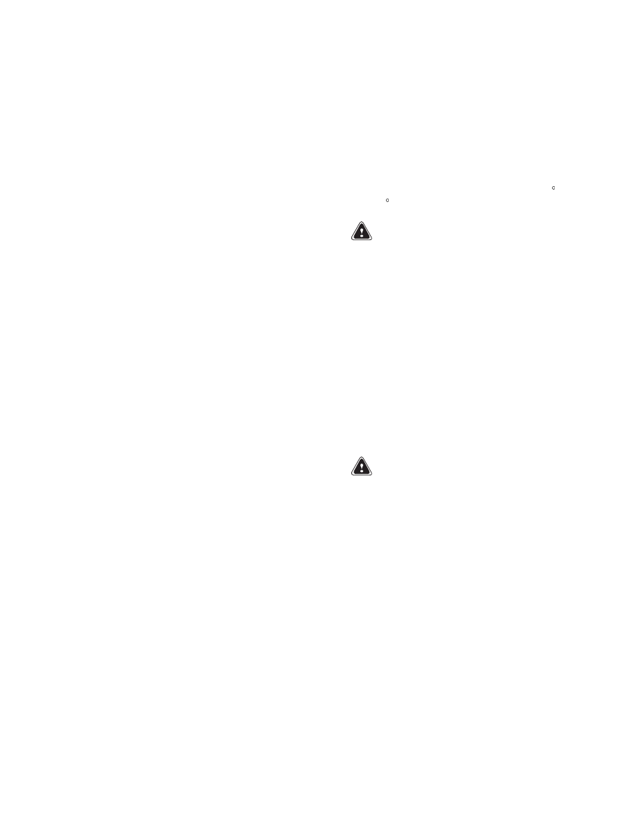
STEP 6.
Support speed reducer with sling and lifting device.
Remove capscrews and nuts that fasten speed re-
ducer to differential housing and carefully pull speed
reducer from differential.
Put speed reducer on a suitable work or storage area.
6
1400 SRM 413
Drive Axle, Speed Reducer, and Differential Repair
DISASSEMBLE
Speed Reducer
1.
Remove access plate from top of speed reducer.
Remove hub cap from end of pinion shaft by hand
or use a small pry bar.
2.
Disassemble only the parts of speed reducer and
differential that must be repaired.
NOTE: If the ring gear and pinion are not to be re-
placed, but parts of the differential must be replaced,
check contact pattern before disassembly. The pat-
tern and the gear clearance are used as references
for assembly. See the Assemble section of this man-
ual for the procedures.
3.
Loosen or remove thrust screw for differential
ring gear. Remove bearing caps, adjusting nuts,
bearing cups, and differential assembly. Make
sure you do not change parts from right and left
sides of differential.
4.
Use a sharp punch to raise lock detent from slot
in pinion shaft. Raise lock detent as carefully as
possible so there is minimum damage to threads
on pinion shaft when special lock nut is removed.
5.
Use a soft piece of metal (copper or aluminum) to
prevent speed reducer gear from turning when
special lock nut is removed. Use soft piece of
metal between speed reducer gears or between
speed reducer gear and housing. Remove special
lock nut. This special lock nut is tightened to
430 N•m (320 lbf ft). Discard special lock nut.
Use a new special lock nut for assembly.
6.
Remove special washer with key tab. Use a brass
hammer to remove pinion from speed reducer
case. The speed reducer gear and outer spacer
will slide from pinion shaft as it is removed from
speed reducer case. Make a note of shim arrange-
ment between bearing and outer spacer.
7.
Remove speed reducer gear and outer spacer
from speed reducer case.
8.
Remove inner spacer from pinion shaft. Use a
press to remove bearing cone from pinion. Make
a note of shim arrangement between bearing
cone and pinion.
9.
Use a press or a puller to remove bearing cones
from speed reducer case.
Differential
1.
Remove ring gear from differential assembly. Re-
move twelve 1/2 UNF × 1-3/4 inch bolts and spe-
cial hardened washers. Do not use a press or
a hammer to remove the ring gear. Heat dif-
ferential in hot oil or water, 82 to 100 C (180 to
212 F), to loosen ring gear.
WARNING
Hot parts. Wear protective clothing and gloves
to prevent burns.
2.
Disassemble the differential. Remove eight 1/2
20-UNF capscrew and washers and separate dif-
ferential case. Remove cross, spider gears, and
axle gears.
3.
Remove bearing retainer for input gear to speed
reducer. Remove four M8 × 1.25 × 25 capscrews
and washers. Remove bearing retainer, gear, and
bearings. Make a note of shim arrangement be-
tween retainer and speed reducer case. Use a
puller to remove inner bearing cup from speed
reducer case.
CLEAN
WARNING
Always wear safety glasses.
Cleaning solvents may be flammable and toxic
and can cause severe skin irritation. When us-
ing cleaning solvents, always comply with the
solvent manufacturer’s recommended safety
precautions.
Compressed air can move particles so that they
cause injury to the user or to other personnel.
Wear protective goggles or a face shield to pre-
vent injury to the eyes.
Clean parts of drive axle with solvent. Dry parts with
compressed air.
7
Drive Axle, Speed Reducer, and Differential Repair
1400 SRM 413
INSPECT
1.
Check pinion and ring gear for wear. Inspect spi-
der gears and axle gears for worn teeth. Inspect
cross for wear where gears turn. The cross and
holes for the cross in the differential case must
fit tightly.
2.
Inspect bearings and seals for defects.
3.
The mount brackets must turn freely on the axle
housings. The splines for the axle shafts must
not be damaged.
ASSEMBLE
Speed Reducer
Input Gear, Install
1.
Install bearing cup in end of bore in speed re-
ducer case. Use a press to install bearing cones
on each end of input gear. Install input gear and
bearings into speed reducer case. Install outer
bearing cup.
2.
Install shims and bearing retainer. Install four
M8 × 1.25 × 25 capscrews and washers. Tighten
capscrews to 19 N•m (14 lbf ft). Check bear-
ing clearance. Add or remove shims to adjust
for zero bearing clearance. The input gear must
turn smoothly with a maximum rotation torque
of 0.133 N•m (1.2 lbf in).
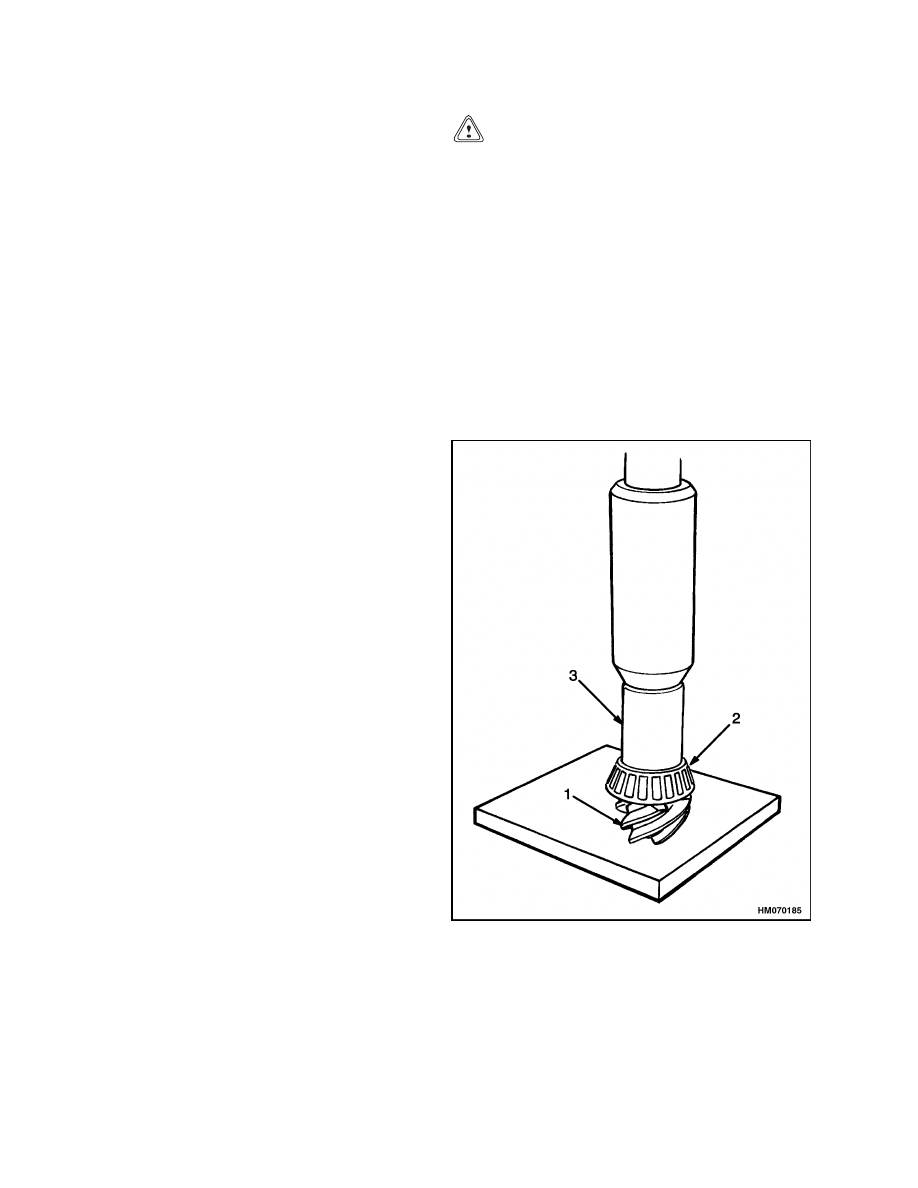
New Pinion, Install
If the ring gear or pinion is worn or damaged, they
must be replaced as a set. See Figure 4. The ring
gear and pinion must have the same reference num-
bers. When the pinion bearings are replaced or the
ring gear and pinion are replaced, the shim arrange-
ment must be adjusted for the new parts. Service
persons must often make more than one adjustment
before the clearances are correct. The speed reducer
must be disassembled for shim adjustment and then
assembled again for checks. The adjustments are
correct when the gear clearance and contact pattern
between the pinion and ring gear are correct and the
preload on the pinion bearings is correct.
CAUTION
Do not lock the special nut on the pinion shaft
until the adjustments of the pinion are com-
plete. The lock on the special nut will damage
the threads on the pinion shaft if the special
nut must be removed several times for adjust-
ments. If the threads are damaged on the pin-
ion shaft, the pinion and ring gear must be re-
placed.
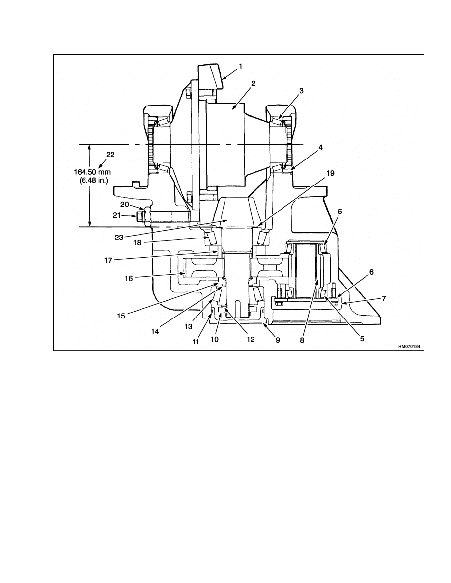
The dimension on the end of the pinion is the vari-
ation from the test dimension. See Figure 5. The
test dimension is the distance from the center of the
ring gear to the bearing shoulder behind the pinion
gear. Shims must be added between the pinion and
the bearing to adjust for manufacturing tolerances.
See Table 1.
1.
PINION
2.
BEARING CONE
3.
PRESS TOOL
Figure 4. Use Press to Install Pinion Parts
8
1400 SRM 413
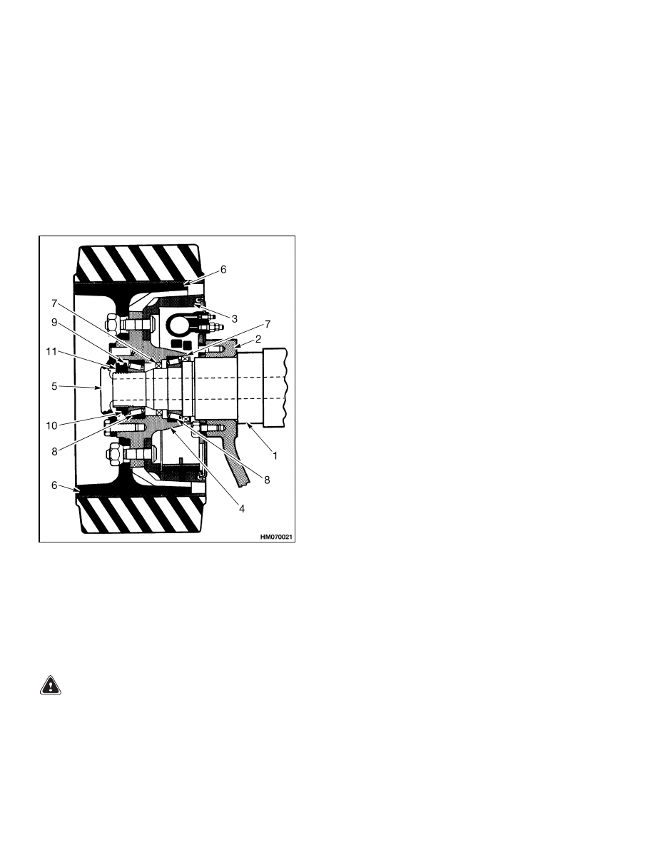
Drive Axle, Speed Reducer, and Differential Repair
1.
RING GEAR
2.
DIFFERENTIAL ASSEMBLY
3.
BEARING
4.
ADJUSTER NUT
5.
BEARING (2)
6.
SHIM
7.
RETAINER
8.
GEAR
9.
HUB CAP
10. SPECIAL NUT
11. O-RING
12. WASHER (KEYED)
13. BEARING
14. SHIMS
15. SPACER
16. GEAR
17. SPACER
18. BEARING
19. SHIMS
20. JAMNUT
21. THRUST SCREW
22. TEST DIMENSION*
23. PINION
*THE TEST DIMENSION IS 164.50 mm (6.48 in.) PLUS OR MINUS THE VARIATION SHOWN ON THE END OF
THE PINION. THE ADJUSTMENT MUST BE ±0.025 mm (0.001 in.) OF THE ACTUAL DISTANCE.
Figure 5. Differential and Speed Reducer Assembly
9
Drive Axle, Speed Reducer, and Differential Repair
1400 SRM 413
Table 1. Pinion Assembly Shims Adjustment
Examples
1
2
3
4
Number of OLD PINION
Number on (NEW PINION)
+0.31
(+0.26)
+0.31
( 0.26)
+0.26
(+0.31)
+0.26
(+0.31)
Shims to be REMOVED FROM or
ADDED TO the old set.
0.05 mm
REMOVE
0.57 mm
REMOVE
0.05 mm
ADD
0.57 mm
ADD
Look at the number on the pinion that was removed. Subtract the variation number that is on the pinion.
The remainder is the amount of shim thickness that must be removed from the shim set on the pinion
that was removed. (In examples 3 and 4, you can see that shims must be added. Examples 1 and 2 show
that shims must be subtracted from the original shim set. Use this shim set as a reference. The final
adjustment of the shims is set according to the contact pattern on the teeth of the ring gear. See Ring
and Pinion Tooth Contact Adjustment.
NOTE: The pinion and ring gear are made in sets.
Both the ring gear and pinion have marks with the
same number. If the original pinion is not available
and the + or
dimension is not known, adjust the
pinion to the test dimension shown in Figure 5. The
test dimension is 164.50 mm (6.48 in.). Use shims
between the pinion and the bearing to obtain the test
dimension + or
0.025 mm (0.001 in.).
1.
If the bearing cups for the pinion were removed,
install them in speed reducer case.
2.
Install shims on pinion and use a press to install
bearing cone. Install spacer on pinion shaft. See
Figure 6.
3.
Put speed reducer gear and spacer in speed re-
ducer case. Install pinion in speed reducer case
and slide speed reducer gear and spacer on pin-
ion shaft when it is installed.
4.
Install shims on pinion shaft that control preload
on pinion bearings. Install bearing cone, washer
with key tab, and special lock nut. Use a soft
piece of metal (copper or aluminum) as a wedge
to prevent speed reducer gear from turning.
Tighten special lock nut to 430 N•m (320 lbf ft).
Do not lock special nut to 430 N•m (320 lbf ft).
Do not lock special nut at this time.
5.
Check rotating torque of pinion and speed re-
ducer assembly. The correct rotating torque is
1.13 to 2.26 N•m (10 to 20 lbf in). Lightly hit out-
side of housing to adjust bearings in their seats.
Add or remove shims between spacer and bear-
ing cone to adjust bearing preload.
Figure 6. Bearing Cones Installation
Differential
1.
Lubricate and install an axle gear and thrust
washer in speed reducer case. Put spider gears
and thrust washer on cross and put spider gear
assembly into speed reducer case. Install second
axle gear and thrust washer. Put two halves of
speed reducer case together and install eight 1/2
20-UNF capscrews and washers. Tighten cap-
screws to 140 N•m (103 lbf ft).
10
1400 SRM 413
Drive Axle, Speed Reducer, and Differential Repair
2.
If ring gear was removed from speed reducer
case, put ring gear into hot oil or water [82
to 100 C (180 to 212 F)] for approximately 10
minutes. Remove ring gear from the liquid and
put it into position on speed reducer case. Do
not use a press or a hammer to install ring gear.
Install 12-1/2 UNF × 1-3/4 inch bolts and special
hardened washers. Tighten bolts to 140 N•m
(103 lbf ft). Make sure ring gear is in correct
position against flange of speed reducer case.
WARNING
Hot parts. Wear protective clothing and gloves
to prevent burns.
3.
Use a press to install bearing cones on each side
of speed reducer case.
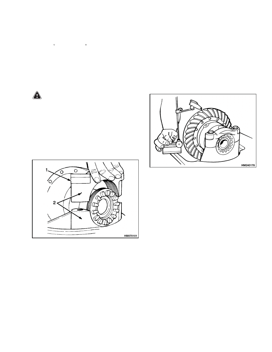
4.
Install differential assembly, bearing cups, ad-
justing nuts, and bearing caps in speed reducer
housing. Make sure parts are installed in their
original positions. Tighten capscrews for bearing
caps to 225 N•m (166 lbf ft). See Figure 7.
1.
BEARING CAP
2.
MATCH MARKS
Figure 7. Bearing Caps Installation
5.
Tighten adjusting nuts to 14 N•m (10 lbf ft) to re-
move clearance between adjusting nuts and bear-
ings. Make sure there is clearance between ring
gear and pinion. Loosen one adjusting nut until
there is zero clearance between bearings and ad-
justing nut. Tighten adjusting nut three notches
more than zero clearance to put a preload on
bearings.
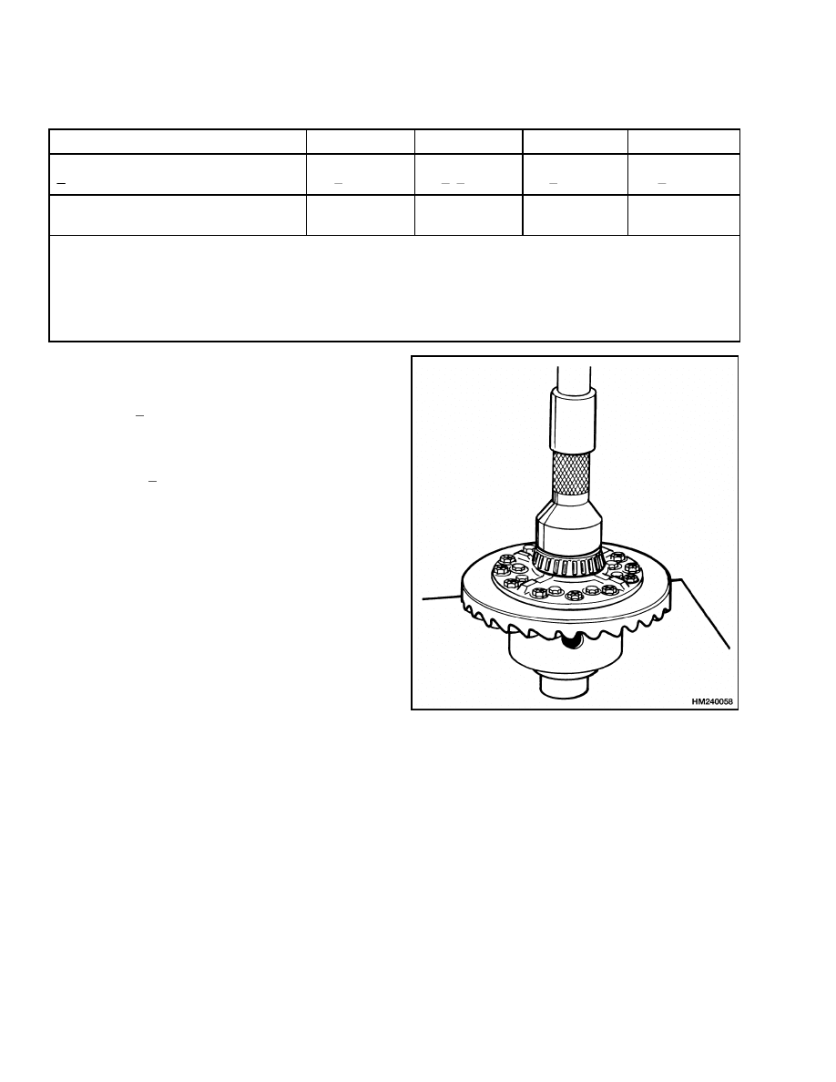
6.
Check clearance between ring gear and pinion.
The ring gear and pinion must have a clearance
of 0.254 to 0.330 mm (0.010 to 0.013 in.). Use ad-
justing nuts to move ring gear toward or away
from engagement with pinion gear. Loosen one
adjusting nut the same amount as the other ad-
justing nut is tightened to adjust clearance be-
tween ring gear and pinion. See Figure 8.
Figure 8. Clearance Check Between Ring Gear
and Pinion
7.
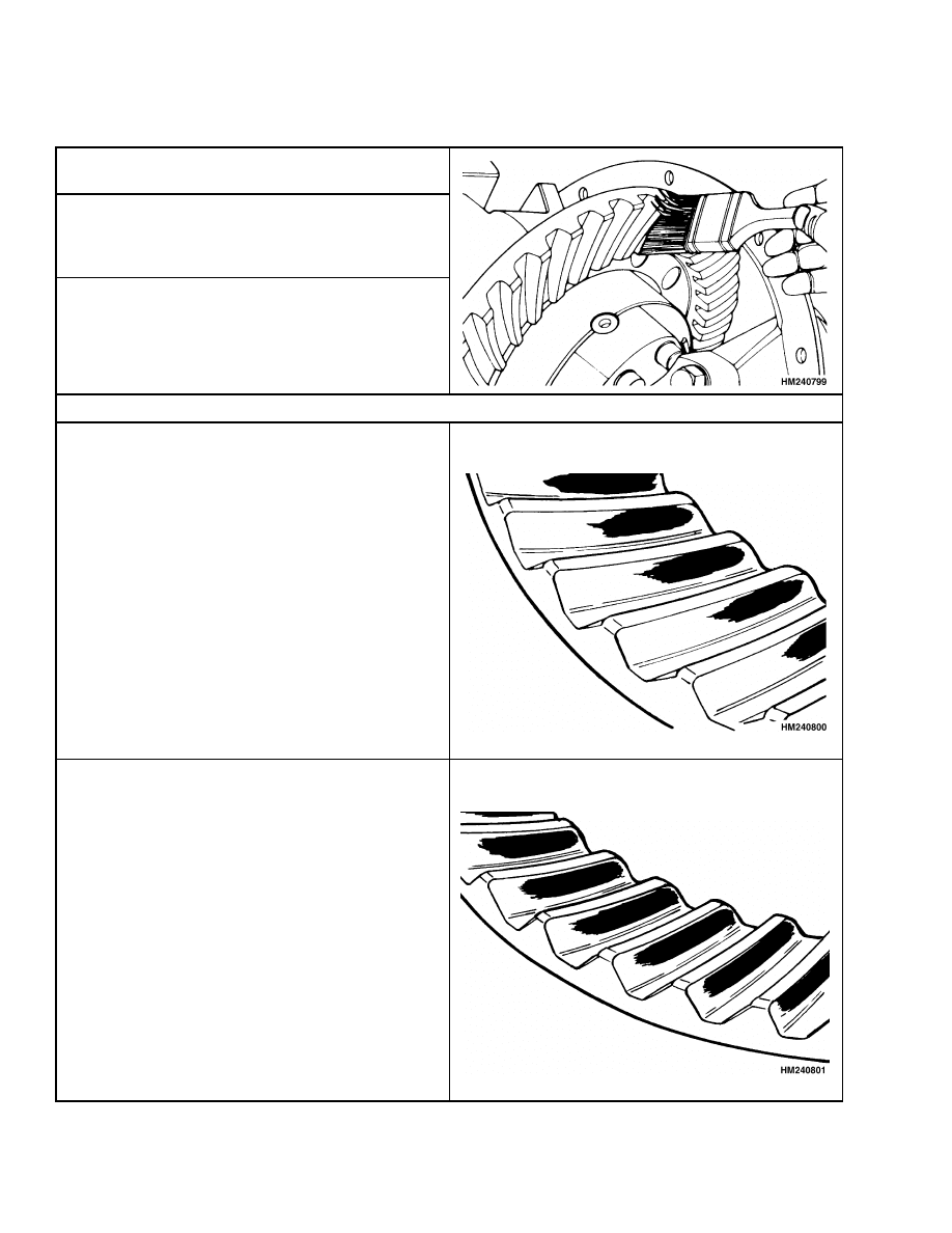
Check pattern on teeth of ring gear. Apply an in-
dicator color (Prussian blue or yellow) to teeth.
Use a pry bar between ring gear and housing to
prevent ring gear from turning freely. Turn pin-
ion shaft. Compare pattern on ring gear teeth
with patterns shown in Ring and Pinion Tooth
Contact Adjustment. Adjust gear clearances as
necessary.
8.
Install lock plates for adjusting nuts. Tighten
capscrews to 19 N•m (14 lbf ft).
9.
Make sure special lock nut has been tightened
to 430 N•m (318 lbf ft). Use a punch with an 8
mm round tip to lock special nut on end of pinion
shaft. Make sure the metal from the special nut
contacts bottom of slot in pinion shaft.
11
Drive Axle, Speed Reducer, and Differential Repair
1400 SRM 413
Table 2. Ring and Pinion Tooth Contact Adjustment
1.
Apply a colored dye or grease to approximately 12
of the ring gear teeth.
2.
Rotate ring gear forward and backward so that
the 12 gear teeth go past the drive six times to
get to the contact patterns. Repeat if needed to
get a clearer pattern.
3.
Check the tooth contact pattern on the ring gear.
Make sure that the pattern is checked on the side
of the tooth where the pinion applies the force.
Correct Tooth Contact
The contact area is the center between the top and
bottom of the tooth. The contact area is toward the
inner circumference of the ring gear.
NOTE: Normal pattern during adjustment shown.
The contact area is the center between the top and
the bottom of the tooth. The contact area will be
almost the full length of the tooth.
NOTE: Wear pattern from operation shown.
12
1400 SRM 413
Drive Axle, Speed Reducer, and Differential Repair
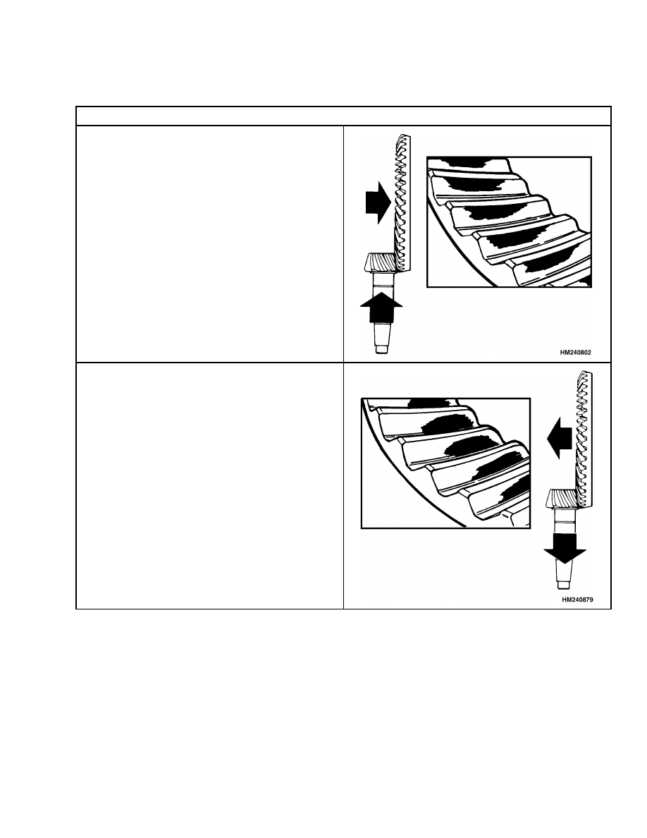
Table 2. Ring and Pinion Tooth Contact Adjustment (Continued)
Incorrect Tooth Contact
The pinion is too far away from the center of the
gear. Add shims to move pinion toward ring gear.
Check that the clearance is correct. Some movement
of ring gear away from pinion may be necessary.
The pinion is too close to the center of the ring gear.
Remove shims to move pinion away from the ring
gear. Check that the clearance is correct. Some
movement of the ring gear toward the pinion may
be necessary.
10. Install thrust screw. Tighten thrust screw until
it touches ring gear. Loosen screw until there is
0.38 to 0.50 mm (0.015 to 0.020 in.) clearance
between end of thrust screw and end of ring gear.
Tighten lock nut.
11. Install hub cap and O-ring in speed reducer case
at end of pinion nut. Apply liquid sealant to ac-
cess plate and install it on speed reducer case
over speed reducer.
12. See Drive Axle Housing for installation proce-
dure.
13
Drive Axle, Speed Reducer, and Differential Repair
1400 SRM 413
DRIVE AXLE HOUSING
Remove
NOTE: Normally, the drive axle housing will not need
to be removed from the lift truck unless the axle is to
be replaced.
The following procedure assumes the traction motor,
speed reducer, and differential assemblies have been
previously removed from the drive axle housing. See
Figure 9.
1.
AXLE HOUSING
2.
AXLE MOUNT
3.
BRAKE SYSTEM
4.
HUB
5.
AXLE SHAFT
6.
WHEEL
7.
SEAL
8.
BEARING
ASSEMBLY
9.
ADJUSTMENT NUT
10. LOCKWASHER
11. LOCK NUT
Figure 9. Drive Axle
1.
Remove drive wheels.
WARNING
Brake lining contains asbestos fibers. Breath-
ing asbestos dust is a cancer and lung disease
hazard. Do not create dust! Do not clean brake
parts with compressed air or by brushing. Use
vacuum equipment for asbestos or follow the
cleaning procedure in this section. When the
brake drums are removed, do not create dust.
Do not sand, grind, chisel, hammer, or change
linings in any way that will create dust. Any
changes to linings must be done in a restricted
area with special ventilation. Protective cloth-
ing and a respirator must be used.
2.
Remove nut, lockwasher, and flat washer. Re-
move hub, brake drum, and bearings. If brake
drum cannot be easily removed, loosen brake
shoes by turning adjuster wheel.
3.
Disconnect brake lines at wheel cylinders. Re-
move brake shoe assemblies from back plates.
Remove back plates from axle housings.
4.
Use a lifting device to hold the weight of the axle
housing.
5.
The drive axle mounting pins must be pressed
or pulled from the frame and axle mounts. Use
one of the following two methods to remove and
install mounting pins:
• A machined spacer (cup), capscrew, washer,
and nut arrangement and a long-handled
ratchet
• A port-a-power type hydraulic tool with a hol-
low piston and a threaded rod of the appropri-
ate length (see Figure 10)
6.
Use one of the two methods shown in Figure 10
and remove mounting pins from frame and axle
mount. Remove capscrews that hold axle mounts
to frame. Remove mounts from axle housings.
NOTE: If a mounting pin cannot be removed, soak it
in penetrating oil or use a hacksaw blade to saw a slot
in the pin. Use the procedure shown in Figure 10 to
remove the pin.
Clean
1.
Do not release asbestos dust into the air when
brake drum is removed.
2.
Use a solvent to wet asbestos dust on the parts
of the brake. If a solvent spray is used, do not
create asbestos dust with the spray.
3.
When the asbestos dust is wet, clean parts. Put
any cloth or towels in a plastic bag or an airtight
container while they are still wet. Put an AS-
BESTOS warning label on plastic bag or airtight
container.
14
1400 SRM 413
Drive Axle, Speed Reducer, and Differential Repair
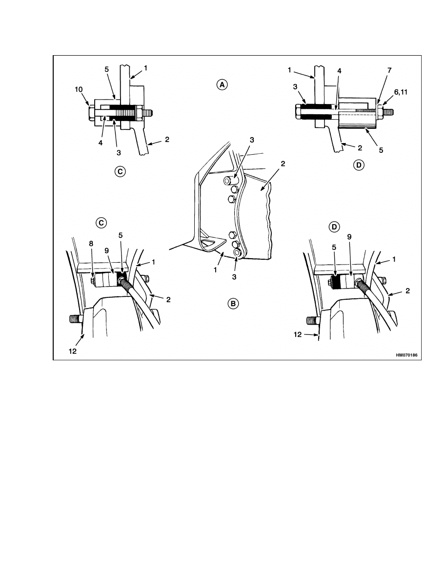
A. METHOD 1
B. METHOD 2
C. REMOVAL
D. INSTALLATION
1.
FRAME
2.
AXLE MOUNT
3.
MOUNTING PIN
4.
CAPSCREW
5.
SPACER (CUP)
6.
NUT
7.
WASHER
8.
THREADED ROD
9.
PORT-A-POWER
10. TIGHTEN CAPSCREW TO REMOVE PIN
11. TIGHTEN NUT TO INSTALL PIN
12. BRAKE DRUM (REF)
Figure 10. Axle Mount, Pin Removal and Installation
4.
Any cleaning cloths that will be washed must be
cleaned so asbestos fibers are not released into
the air.
5.
Clean all parts of drive axle with solvent. Dry
with compressed air.
Inspect
Inspect bearings and seals for defects. The axle hous-
ings must rotate freely in mounts. The splines for the
axle shafts must not be damaged.
15

Drive Axle, Speed Reducer, and Differential Repair
1400 SRM 413
Assemble
1.
Use lifting device to hold axle housing. Apply
sealant, Hyster Part No. 264159, on the flange
of the axle housing. See Figure 1, Figure 9, and
Figure 10.
2.
Lubricate the surface for the axle mounts on
the axle housing with an antiseize compound.
Slide axle mounts onto axle housing. Align axle
mounts with frame and install axle housing
onto speed reducer housing. Install capscrews
and washers.
Tighten capscrews to 65 N•m
(48 lbf ft).
3.
Install capscrews for axle mounts, but do not
tighten them. Lubricate mounting pins with an
antiseize compound. Use the procedure shown in
Figure 10 to install the mounting pins in the axle
mounts and the frame. After the mounting pins
are installed, tighten capscrews for axle mounts
to 320 N•m (236 lbf ft).
a. Method 1. See Figure 10.
(1)
Use a grade 8 capscrew the maximum
diameter possible and long enough
to pass through the spacer (cup) and
mounting pin. Put a washer and nut
on threaded end against mounting pin.
The washer and nut must be smaller
than the holes in the frame and axle
mount.
(2)
Install spacer and capscrew through
mounting pin from frame side. Use a
socket and ratchet to pull mounting pin
out of (removal), or into (installation),
axle mount and frame members.
b. Method 2 - Bottom Pins Only. See Fig-
(1)
Use a capscrew as in Method 1, but long
enough to pass through spacer, port-a-
power with a hollow piston, and mount-
ing pin.
The washer and nut on the
end of the capscrew must be smaller
than the holes in the frame and the axle
mount when the pin is removed.
(2)
Install spacer, port-a-power with a
hollow piston, and capscrew assembly
through mounting pin from frame side.
Operate port-a-power in the direction
away from frame and pull mounting pin
out of (removal), or into (installation),
axle mount and frame members.
c.
Method 2 - Top Pins Only. See Figure 10.
(1)
The long capscrew used to remove the
bottom pins cannot be used at the top
because there is a restriction at the
frame sides. Use a rod threaded at both
ends and the appropriate length in-
stead of capscrew. The diameter of the
threaded rod must be smaller to allow
clearance to move the port-a-power at
an angle in the restricted space.
(2)
Install spacer, port-a-power with a
hollow piston, and threaded rod assem-
bly through mounting pin from frame
side. Operate port-a-power in the direc-
tion away from the frame and pull the
mounting pin out of (removal), or into
(installation), axle mount and frame
members.
4.
Assemble brake assembly to mount for axle hous-
ing as described in the section Brake System
1800 SRM 338.
5.
Install seal in center of hub.
Lubricate inner
bearing with grease. Install inner seal in hub.
Install brake drum on hub. Install hub and brake
drum on axle.
Use care not to damage seals
when installing hub.
Lubricate outer bearing
cone with grease and install outer bearing cone.
6.
Install adjustment nut. Tighten nut to 205 N•m
(151 lbf ft) while rotating hub. Loosen nut un-
til hub rotates freely. The torque must be less
than 25 N•m (18 lbf ft). Tighten nut to 35 N•m
(26 lbf ft) or to the first alignment position af-
ter 35 N•m (26 lbf ft). Install lockwasher to hold
nut. Install lock nut and tighten it to 135 N•m
(100 lbf ft).
7.
Apply sealant Hyster Part No. 264159, to flange
of axle shaft. Install axle shaft. Tighten cap-
screws to 225 N•m (166 lbf ft).
16

1400 SRM 413
Troubleshooting
CAUTION
When the wheels have been installed, check
all wheel nuts after 2 to 5 hours of opera-
tion.
Tighten the nuts in a cross pattern
to the correct torque value.
When the nuts
stay tight after an 8-hour check, the interval
for checking the torque can be extended to
350 hours for lift truck models E3.50-5.50XL
(E70-120XL) (C098) or 500 hours for lift truck
models E3.50-5.50XL (E70-120XL
3
) (C098) and
E3.50-5.50XL,
E4.50XLS
(E70-120Z,
E100ZS)
(D098)
8.
Install wheels.
Tighten wheel nuts to 610 to
680 N•m (450 to 502 lbf ft).
9.
Install the mast assembly as described for lift
truck models E3.50-5.50XL (E70-120XL) (C098)
in section Vista
®
Masts, Description and Re-
pairs For Lift Trucks with 3,500 to 6,000 kg
(7,000 to 12,000 lb) Capacities 4000 SRM 340
or E3.50-5.50XL (E70-120XL
3
) (C098) and E3.50-
5.50XL, E4.50XLS (E70-120Z, E100ZS) (D098) in
section Masts, Description and Repairs 4000
SRM 736 for your specific lift truck.
10. Install the battery as described in the section
Periodic Maintenance 8000 SRM 291 for lift
truck models E3.50-5.50XL (E70-120XL) (C098),
Periodic Maintenance 8000 SRM 915 for
lift truck models E3.50-5.50XL (E70-120XL
3
)
(C098),
or
Periodic
Maintenance
8000
SRM 1201 for lift truck models E3.50-5.50XL,
E4.50XLS (E70-120Z, E100ZS) (D098). Fill dif-
ferential housing with Ultra Gear Lubrication
Gear Oil
®
SAE 80W (Chevron) through fill hole.
Remove air from brake system as described in
the section Brake System 1800 SRM 338.
Troubleshooting
PROBLEM
POSSIBLE CAUSE
PROCEDURE OR ACTION
The lift truck will not move.
An axle shaft is broken.
Install new axle shaft.
The differential is damaged.
Repair differential.
The drive axle has leaks.
The drain or fill plug has damaged
threads or is loose or missing.
Repair threads. Tighten plug. Install
missing part.
The O-rings or seals have damage.
Install new O-rings and seals.
The drive axle housing is cracked.
Install new drive axle housing.
The drive axle makes noise.
The bearings have damage.
Install new parts.
The brake assembly is damaged.
Repair brake assembly.
The oil level is low.
Fill as required. Check for leaks.
The axle mounting capscrews are
loose.
Tighten
capscrews
to
specified
torque.
17

NOTES
____________________________________________________________
____________________________________________________________
____________________________________________________________
____________________________________________________________
____________________________________________________________
____________________________________________________________
____________________________________________________________
____________________________________________________________
____________________________________________________________
____________________________________________________________
____________________________________________________________
____________________________________________________________
____________________________________________________________
____________________________________________________________
____________________________________________________________
____________________________________________________________
____________________________________________________________
____________________________________________________________
____________________________________________________________
____________________________________________________________
18


TECHNICAL PUBLICATIONS
1400 SRM 413
3/05 (2/04)(7/00)(7/99)(2/96)(9/88) Printed in United Kingdom
Document Outline
- toc
- tables
Wyszukiwarka
Podobne podstrony:
897953 1600SRM0639 (03 2005) UK EN
1598459 1900SRM1213 (03 2005) UK EN
897956 1900SRM0642 (03 2005) UK EN
897963 4500SRM0649 (03 2005) UK EN
897670 1400SRM0575 (04 2005) UK EN
1573930 0600SRM1172 (03 2005) UK EN
1586985 2200SRM1178 (03 2005) UK EN
1531815 1800SRM1040 (03 2005) UK EN
899782 2000SRM0077 (03 2005) UK EN
1574068 1400SRM1171 (08 2005) UK EN
897875 8000SRM0616 (03 2005) UK EN
897961 2200SRM0647 (03 2005) UK EN
1597925 0700SRM1211 (03 2005) UK EN
1586982 0100SRM1177 (03 2005) UK EN
1466169 4000SRM0741 (03 2005) UK EN
1495208 8000SRM0949 (03 2005) UK EN
1458783 8000SRM0592 (03 2005) UK EN
1589731 2200SRM1184 (03 2005) UK EN
więcej podobnych podstron