ELECTRICAL SYSTEM
REPLACEMENT, CHECKS, AND
ADJUSTMENTS
RS45-30CH, RS45-27IH, RS46-33CH, RS46-30IH,
RS46-36CH, RS46-33IH Up to 1562, 1564,
1565, and 1569 [A222]
PART NO. 897961
2200 SRM 647

SAFETY PRECAUTIONS
MAINTENANCE AND REPAIR
• When lifting parts or assemblies, make sure all slings, chains, or cables are correctly
fastened, and that the load being lifted is balanced. Make sure the crane, cables, and
chains have the capacity to support the weight of the load.
• Do not lift heavy parts by hand, use a lifting mechanism.
• Wear safety glasses.
• DISCONNECT THE BATTERY CONNECTOR before doing any maintenance or repair
on electric lift trucks. Disconnect the battery ground cable on internal combustion lift
trucks.
• Always use correct blocks to prevent the unit from rolling or falling. See HOW TO PUT
THE LIFT TRUCK ON BLOCKS in the Operating Manual or the Periodic Mainte-
nance section.
• Keep the unit clean and the working area clean and orderly.
• Use the correct tools for the job.
• Keep the tools clean and in good condition.
• Always use HYSTER APPROVED parts when making repairs. Replacement parts
must meet or exceed the specifications of the original equipment manufacturer.
• Make sure all nuts, bolts, snap rings, and other fastening devices are removed before
using force to remove parts.
• Always fasten a DO NOT OPERATE tag to the controls of the unit when making repairs,
or if the unit needs repairs.
• Be sure to follow the WARNING and CAUTION notes in the instructions.
• Gasoline, Liquid Petroleum Gas (LPG), Compressed Natural Gas (CNG), and Diesel fuel
are flammable. Be sure to follow the necessary safety precautions when handling these
fuels and when working on these fuel systems.
• Batteries generate flammable gas when they are being charged. Keep fire and sparks
away from the area. Make sure the area is well ventilated.
NOTE: The following symbols and words indicate safety information in this
manual:
WARNING
Indicates a condition that can cause immediate death or injury!
CAUTION
Indicates a condition that can cause property damage!

Electrical System
Table of Contents
TABLE OF CONTENTS
General ...............................................................................................................................................................
Engine Electrical System ..................................................................................................................................
Batteries and Battery Disconnect.................................................................................................................
Alternator.......................................................................................................................................................
Repair.........................................................................................................................................................
Starting Circuit..............................................................................................................................................
Starter Repair ................................................................................................................................................
Sensors and Switches ........................................................................................................................................
Electrical System for Operator Compartment .................................................................................................
Heater Components, Replace ........................................................................................................................
Electrical Control System..................................................................................................................................
Switch Controls..............................................................................................................................................
Instrument Panel Components, Replace ......................................................................................................
Joystick Switches...........................................................................................................................................
Replace .......................................................................................................................................................
Joystick Internal Components ......................................................................................................................
Intermodal Control Switches ........................................................................................................................
Spreader Control Switches............................................................................................................................
Switch Replacement On Control Panels ......................................................................................................
Control Box Components...............................................................................................................................
Kruger Electrical System ..................................................................................................................................
Troubleshooting..................................................................................................................................................
This section is for the following models:
RS45-30CH, RS45-27IH, RS46-33CH, RS46-30IH, RS46-36CH, RS46-33IH
Up to 1562, 1564, 1565, and 1569 [A222]
©2005 HYSTER COMPANY
i

"THE
QUALITY
KEEPERS"
HYSTER
APPROVED
PARTS

2200 SRM 647
General
General
WARNING
Disconnect the battery cables before doing any
disassembly and repair to the parts of the elec-
trical system.
Always disconnect the battery ground cable be-
fore making repairs.
The diodes and resistors in the electrical sys-
tem can be damaged if the following are not fol-
lowed:
• Do not disconnect the batteries when the en-
gine is running. The voltage surge can dam-
age the diodes and resistors in the electrical
system.
• Do not disconnect an electric wire before the
engine is stopped and the switches are in the
OFF position.
• Do not cause a short circuit by connection
of the electric wires to the wrong terminals.
Make sure a correct identification is made of
the wire before it is connected.
• Make sure a battery is the correct voltage and
polarity before it is connected.
• Do not check for current flow by making a
spark because the electronic components can
be damaged.
• These lift trucks have a 24-volt electrical sys-
tem (two 12-volt batteries in series). Be care-
ful when working on the electrical system.
CAUTION
When using an arc welder, always disconnect
the ground lead from the lift truck batteries
to prevent alternator or battery damage. At-
tach the welding ground clamp as close to the
weld area as possible to prevent welding cur-
rent from damaging bearings.
There are four electrical systems. There is the en-
gine electrical system, the electrical system for the
operator compartment functions, the lights electrical
system, and the electrical control system. This sec-
tion covers the description, operation, and replace-
ment for each of the electrical systems.
There is
also a separate section for the load sensing system.
This system is a hydraulic/electrical system. See the
section Troubleshooting and Adjustments, For
Mark 3E/2 Load Sensing Systems 1900 SRM 642.
The engine electrical system includes the battery,
starter, and alternator.
The electrical system for
the operator compartment functions include the fol-
lowing: the dome light, the fan, the heater controls,
and the three wipers. The lights include the head-
lights, work lights, marker and turn signals at the
front, and the marker, brake, turn, reverse lights,
and reverse alarm lights at the rear. See Figure 4.
The control electrical system includes all the other
electrical devices on the truck for control of all of the
various functions.
The section Diagrams 8000 SRM 594 has all of the
electrical schematic and wiring diagrams for these
electrical systems.
NOTE: The electrical components located on the
boom or attachment are covered in the section Con-
tainer Attachment, ReachStacker 4500 SRM
648 or the section Boom, ReachStacker 4500 SRM
0649.
1
Engine Electrical System
2200 SRM 647
Engine Electrical System
This system has: (1) the batteries, used to provide
the electrical energy for the starter to start the en-
gine and to maintain operation of the electrical de-
vices on the truck; (2) the alternator, used to keep
the batteries charged and provide electrical energy
during operation; and (3) the starter, used to start
the engine.
BATTERIES AND BATTERY DISCONNECT
The two 12-volt batteries are connected in series for
the 24-volt system. The batteries are mounted on the
door of the electrical compartment on the right-hand
side of the lift truck. A battery disconnect switch is
located in the lower left-hand corner of the electrical
compartment and is operated with a key. The switch
disconnects battery power from the starter, alterna-
tor, and fuel shutoff solenoid to prevent engine oper-
ation.
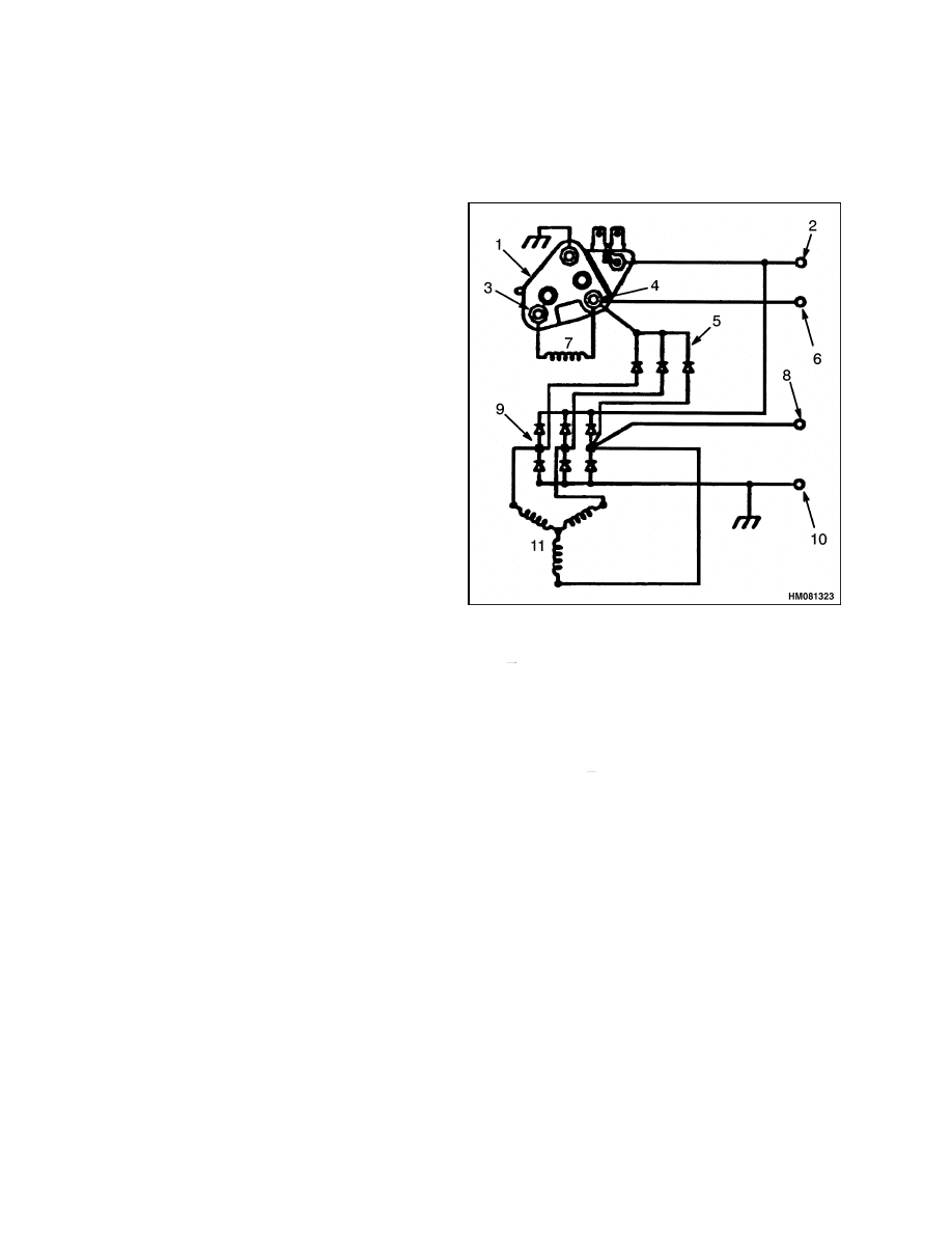
ALTERNATOR
The alternator generates a 24-volt alternating cur-
rent when the engine is running. The alternating
current is changed to a 50 ampere direct current by
six silicon diodes contained in a rectifier assembly
(rectifier bridge). A diode set continues the process
of changing the alternating current to direct current
(DC). The rectifier bridge, diode set, and regulator
are all mounted in the same end frame as the slip
rings. See Figure 1.
Output from the alternator is controlled by the regu-
lator. The regulator controls the alternator output
by controlling the voltage of the field. Voltage for
the regulator is supplied as part of the output volt-
age from the alternator.
The alternator has these main parts:
• stator
• rotor
• two end frames
• solid-state voltage regulator
The direct current, from the diodes, flows to the out-
put or battery (BAT, B+) terminal. The voltage is
controlled by the amount of current flowing through
the field winding in the alternator and the rpm of
the rotor. The voltage regulator inside the frame
contains a transistor, diodes, and capacitors. The
voltage regulator must be replaced if faulty.
1.
REGULATOR
2.
BATTERY (B+) TERMINAL
3.
F
4.
F+
5.
DIODE SET
6.
INDICATOR LIGHT TERMINAL
7.
ROTOR FIELD COIL
8.
RELAY TERMINAL
9.
RECTIFIER BRIDGE, (6) DIODES
10. GROUND (B ) TERMINAL
11. STATOR
Figure 1. Alternator Diagram
The voltage regulator is installed in the end of the al-
ternator that has the slip rings. The voltage regula-
tor controls the current at the output or BAT B+ ter-
minal. The voltage is set by controlling the current in
the field winding of the alternator. This output volt-
age is set by the manufacturer and is not adjustable.
When the key switch is turned to the IGN position,
the voltage regulator is energized. A positive current
flows to the field terminal on the alternator. The bat-
teries send a positive current to the regulator termi-
nal and the battery (BAT B+) terminal.
2
2200 SRM 647
Engine Electrical System
The I or indicator light terminal sends a signal to the
indicator light on the instrument panel to indicate
that the batteries are discharging and the alternator
is ON to charge the batteries. The R or relay terminal
is not used. The B
or ground terminal is connected
to chassis ground.
Repair
NOTE: See your Cummins engines dealer for alter-
nator repair.
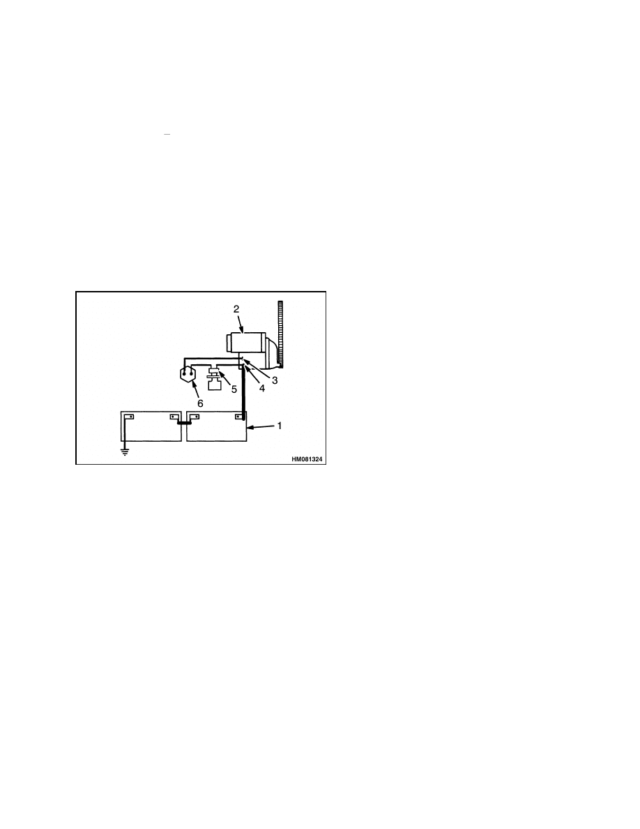
STARTING CIRCUIT
The starting system includes the following (see Fig-
ure 2): (1) batteries, (2) starter, (5) key switch, and
(6) neutral start switch.
NOTE: SEE THE SECTION DIAGRAMS DIAGRAMS
8000 SRM 676 FOR DETAILED CIRCUIT INCLUDING
SHUTOFF CIRCUIT.
1.
BATTERIES
2.
STARTER
3.
S TERMINAL
4.
BATTERY TERMINAL
5.
KEY SWITCH
6.
NEUTRAL START SWITCH
Figure 2. Simplified Starter Circuit
The starter has a drive gear and an idler gear to in-
crease starter torque. It also has a clutch assembly.
The clutch assembly magnetically pushes a small
gear out of the housing to engage the flywheel teeth.
The starter motor rotates the drive gear. The drive
gear engages and rotates the larger idler gear. The
idler gear engages the teeth on the clutch assembly
when the magnet of the solenoid is energized.
A
small gear on the end of the clutch assembly en-
gages the teeth on the flywheel. When the starter
is energized, the solenoid magnet makes the clutch
assembly connect power from the idler gear to the
flywheel.
At approximately the same time, the
starter motor energizes to rotate the flywheel and
start the engine.
Several conditions must be true to start the engine.
The direction control lever must be in the Neutral
position so the transmission is in Neutral and the
neutral start switches are closed. Voltage from the
key switch is applied through the switches to the S
terminal of the starter to energize the starter motor.
There is also an engine shutoff system to protect the
engine and pumps. This system stops the engine if
the engine coolant gets too hot, the engine oil level
is too low, or if the supply valve for the hydraulic oil
is closed. The system stops the engine by de-energiz-
ing the fuel shutoff solenoid to stop fuel flow to the
engine. A system bypass switch on the instrument
panel must be pushed during engine start up to al-
low the engine to start. The transmission must also
be in Neutral.
STARTER REPAIR
NOTE: See your Cummins engines dealer for starter
repair.
3

Sensors and Switches
2200 SRM 647
Sensors and Switches
There are the following sensors and switches on the
ReachStacker:
Air Filter Sensor - Senses when airflow through
the filter is restricted
Switch for Low Coolant Level - Switch closes to
indicate that coolant level is low
High Water Temperature for Engine - Senses
when engine coolant is too hot and stops engine
Engine Water Temperature - Senses engine
coolant temperature
Transmission Speed Sensor - Senses transmission
speed
Engine Speed Sensor - Senses engine speed
Sensor for Transmission Oil Pressure - Senses
pressure of transmission oil
Sensor for Transmission Oil Temperature - Senses
temperature of transmission oil
Switch for Engine Oil Pressure - Senses when en-
gine oil pressure is low
Sensor for Engine Oil Pressure - Senses engine oil
pressure
Shutoff for Low Engine Oil - Senses when engine
oil is too low and stops engine
Fuel Shutoff Solenoid - Solenoid valve to cut fuel
flow when key is moved to the OFF position
Fuel Level Sensor - Senses level of fuel in tank
Air Conditioner Solenoid - Clutch solenoid on pul-
ley to engage optional air conditioner compressor
Switch for Hydraulic Oil Supply - Switch opens to
stop engine when oil supply valve is closed
Oil Filter Switch - Switch closes to indicate when
flow through the hydraulic oil filter is restricted
Sensor for Transmission Oil Filter - Senses when
flow through the transmission oil filter is re-
stricted
Switch for Low Brake Pressure - Switch operates
a warning light when brake pressure is too low
Brake Light Switch - Switch operates a light when
service brakes are applied
Park Brake Switch - Switch operates a light when
parking brakes are applied
Sensor for Top Cylinder Pressure - Senses pres-
sure at the top of the lift cylinders for the Kruger
Controller
Sensor for Bottom Cylinder Pressure - Senses
pressure at the bottom of the lift cylinders for the
Kruger Controller
Oil Temperature Switch for Wet Disk Brake -
Switch closes when temperature of oil for the wet
disk is 270 degrees F or more
Hourmeter - Shows the operating time in hours
and tenths of an hour
NOTE: Sensors and switches cannot be repaired.
They are replaced if damaged or they malfunction.
See the section Instrument Panel Indicators and
Senders 2200 SRM 143 to replace these devices.
4
2200 SRM 647
Electrical System for Operator Compartment
Electrical System for Operator Compartment
This system includes the dome light, the circulating
fan, the heater controls and fan, the three wipers,
and the control switches for these components. The
status indicator lights on the instrument panel are
part of the control system.
NOTE: These components cannot be repaired. They
are replaced if damaged or they malfunction. See
the section Instrument Panel Indicators and
Senders 2200 SRM 143 to replace these devices.
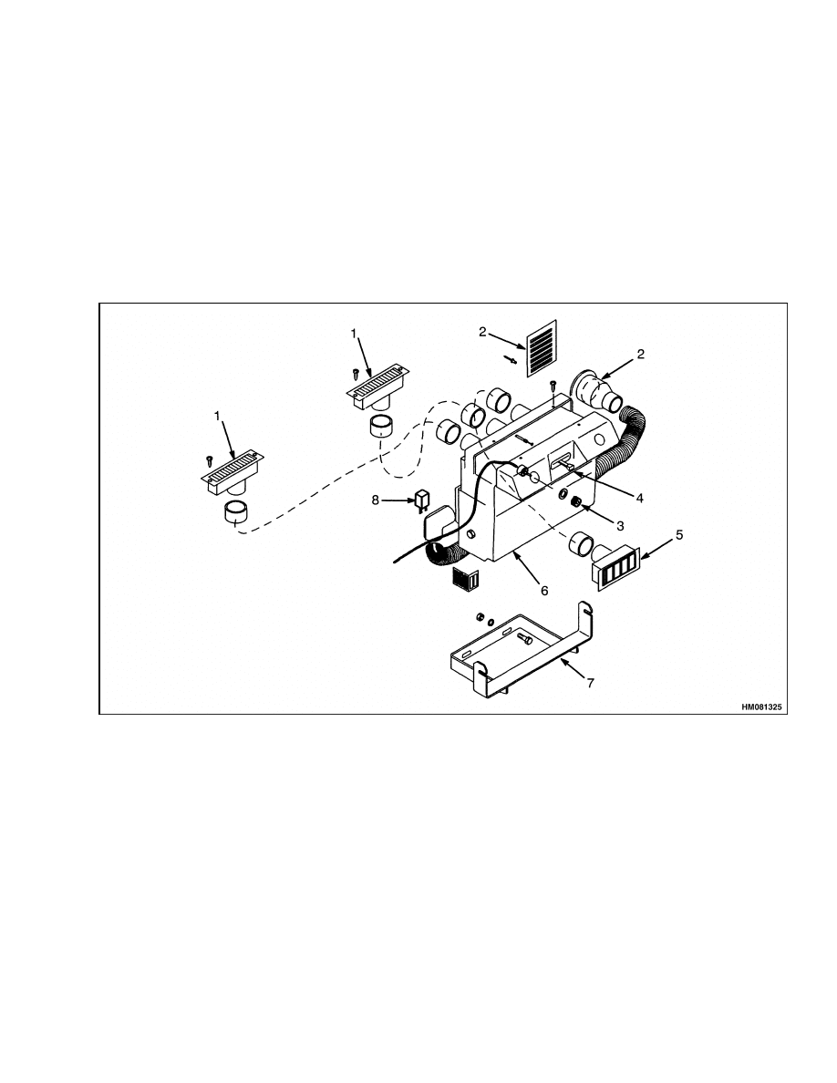
HEATER COMPONENTS, REPLACE
The heater components for the operator compart-
ment are the heater core, fan, and filter.
These
components are in one sealed housing and are re-
placed as a unit.
See Figure 3.
See the section
Frame 100 SRM 631 to replace the heater unit.
1.
DEFROST VENT
2.
AIR INLET
3.
FAN SPEED KNOB
4.
HEAT CONTROL LEVER
5.
HEATER VENT
6.
HEATER UNIT
7.
HEATER MOUNT BRACKET
8.
RESISTOR
Figure 3. Heater Assembly
5

Electrical Control System
2200 SRM 647
Electrical Control System
This system has the switches, solenoids, solenoid
valves, sensors, and other electrical devices to con-
trol functions on the ReachStacker. It also includes
the indicator lights to indicate the status of the
functions for the operator. See Figure 4. See the
section Instrument Cluster 2200 SRM 646 for
more information on the indicator lights.
SWITCH CONTROLS
Switches in the operator compartment operate re-
lays and solenoid valves to control the hydraulic func-
tions. The switches are in consoles of the instrument
panel. See Figure 5. The relays are in the electri-
cal compartment on the right side of the lift truck.
The key for the power disconnect switch operates the
latches of the door on the electrical control box. Most
of the solenoid valves are in the hydraulic compart-
ment on the right side of the lift truck. The following
switches are on the instrument panel:
Engine Start - Held down while key switch is held
in START position to start engine (lower left)
Emergency Engine Stop - Pushed to quickly stop
engine (left end panel)
Chassis Lights - ON to illuminate the marker
lights (upper left) and the chassis work lights
Boom Light - ON to illuminate the boom lights
(upper left)
Beacon Light - ON to illuminate the flashing bea-
con light (upper left)
Kruger Override - Push to ON position to disable
the load sensing system (upper left)
Top Wiper - ON to energize the wiper for the
top window of the operator compartment (upper
right), push further to activate top washer spray.
Rear Wiper - ON to energize the wiper for the
rear window of the operator compartment (upper
right), push further to activate rear washer spray
Front Wiper - ON to energize the wiper for the
front window of the operator compartment (upper
right), push further to activate front washer spray.
Park Brake - Pull to apply the parking brake
(lower right)
Key Switch - OFF, ON, and START positions
(right end panel)
Other Switches - The dome light, circulating fan,
and heater fan switches are located at each device.
There are also switches on the joystick.
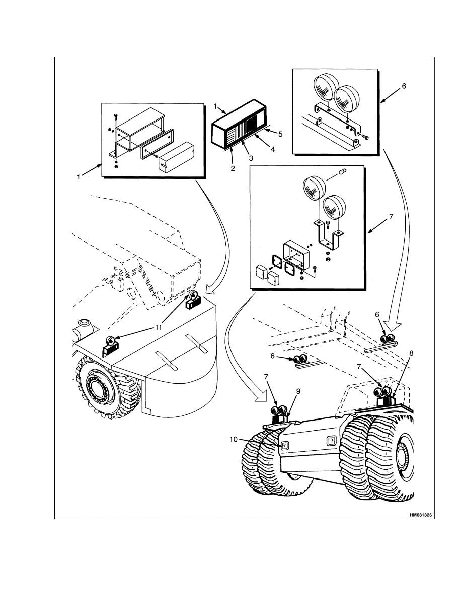
Legend for Figure 4
NOTE: THE 20-FOOT AND 40-FOOT WORK LIGHTS ARE NOT SHOWN.
1.
LIGHT ASSEMBLY
2.
TURN SIGNAL
3.
REAR MARKER AND BRAKE
4.
REFLECTOR
5.
REVERSE ALARM LIGHT
6.
BOOM WORK LIGHTS
7.
FRONT WORK LIGHTS
8.
FRONT TURN SIGNAL
9.
FRONT MARKER
10. HEADLIGHT
11. REVERSE LIGHT
6
2200 SRM 647
Electrical Control System
Figure 4. ReachStacker Lights
7

Electrical Control System
2200 SRM 647
1.
START ENGINE SWITCH
2.
EMERGENCY ENGINE STOP SWITCH
3.
CHASSIS LIGHT SWITCH
4.
BOOM LIGHT SWITCH
5.
BEACON LIGHT SWITCH
6.
KRUGER OVERRIDE SWITCH
7.
TOP WIPER SWITCH
8.
REAR WIPER SWITCH
9.
FRONT WIPER SWITCH
10. KEY SWITCH
11. PARKING BRAKE SWITCH
Figure 5. Instrument Panel Switches
INSTRUMENT PANEL COMPONENTS,
REPLACE
NOTE: Switches do not normally malfunction. Make
sure the circuit breaker and relay operate correctly
before replacing a switch.
Disconnect the power. Make sure the key is in the
OFF position. Remove the cover plate of the instru-
ment panel. Attach labels to the switch wires for cor-
rect connection to the new switch. Remove the wires
from the switch, then compress the clips, and remove
the switch from the plate. Make sure the switch is in
the correct alignment with the top of the switch at
the top of the hole. Install the new switch and con-
nect the wires according to the wire labels. Install
the plate of the instrument panel. See the section
Instrument Panel Indicators and Senders 2200
SRM 143 to replace the indicator lights, meters, and
gauges.
NOTE: The electrical components located on the
boom or attachment are covered in the section Con-
tainer Attachment, ReachStacker 4500 SRM
648 or the section Boom, ReachStacker 4500 SRM
0649. Also see the section Hydraulic System 1900
SRM 641 for the solenoid valves and the section
Diagrams 8000 SRM 594.
8
2200 SRM 647
Electrical Control System
JOYSTICK SWITCHES
Disconnect the power. Make sure the key is in the
OFF position. The joystick has two switch buttons
facing the operator and three switch buttons on the
opposite side of the joystick. See Figure 6. The switch
button on the left facing the operator is the damp-
ening lock. Push this button to prevent forward or
backward swing of the container. The buttons on the
opposite side have three positions. They are spring-
loaded to the center (off) position. The button on the
right is the horn button. The top button controls the
rotation of the attachment. Push the right side to ro-
tate the right side of the attachment toward the op-
erator. Push the left side to rotate the left side of the
attachment toward the operator. Push the right side
of the middle button to make the attachment move to
the right. Push the left side to move the attachment
to the left. The bottom button controls the attach-
ment slope function. Push the right side of the button
to slope the attachment down to the right. Push the
left side of the button to slope the attachment down
to the left.
Figure 6. Joystick Switches
Legend for Figure 6
1.
DAMPENING LOCK
2.
HORN BUTTON
3.
JOYSTICK HANDLE
4.
SPREADER ROTATION
5.
SPREADER SIDESHIFT
6.
SPREADER PILE SLOPE
Replace
NOTE: Switches do not normally malfunction. Make
sure the circuit breaker and relay operate correctly
before replacing a switch.
Disconnect the power. Make sure the key is in the
OFF position. Remove the joystick handle from the
shaft. Carefully open the handle and attach labels
to the switch wires for correct connection to the new
switch. Remove the wires from the switch, then re-
move the switch from the handle. Install the new
switch and connect the wires according to the wire la-
bels. Assemble the handle and install it on the shaft.
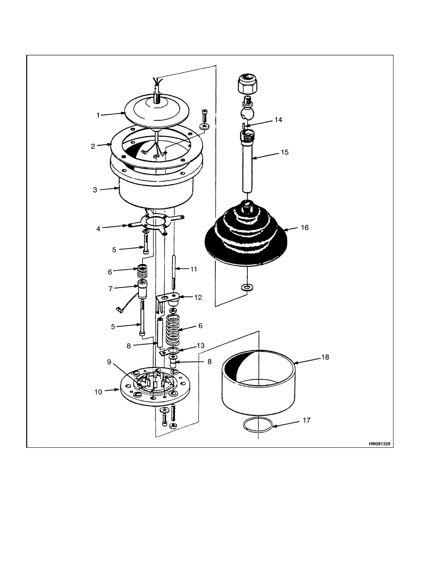
JOYSTICK INTERNAL COMPONENTS
These components are the linkage and potentiome-
ters that control the operation of the four joystick
functions. These four boom functions are: (1) for-
ward to lower the boom, (2) right to extend the boom,
(3) back to raise the boom, and (4) left to retract the
boom. The linkage allows operation of two functions
simultaneously.
Disconnect the power. Make sure the key is in the
OFF position. Replace internal joystick components
by removing the handle and the cover of the box. To
disassemble the internal components, see Figure 7.
9
Electrical Control System
2200 SRM 647
Figure 7. Joystick Control
10
2200 SRM 647
Electrical Control System
Legend for Figure 7
NOTE: HANDLE NOT SHOWN.
1.
CAP
2.
MOUNTING RING
3.
HOUSING
4.
COLLECTOR
5.
SCREW (4)
6.
SPRING (4)
7.
25-OHM POTENTIOMETER (4)
8.
SPACER (4)
9.
DIODE (6)
10. MOUNT RING
11. STUD
12. STOP
13. CONTACT (4)
14. PIN
15. ROD
16. BELLOWS
17. SNAP RING
18. COVER
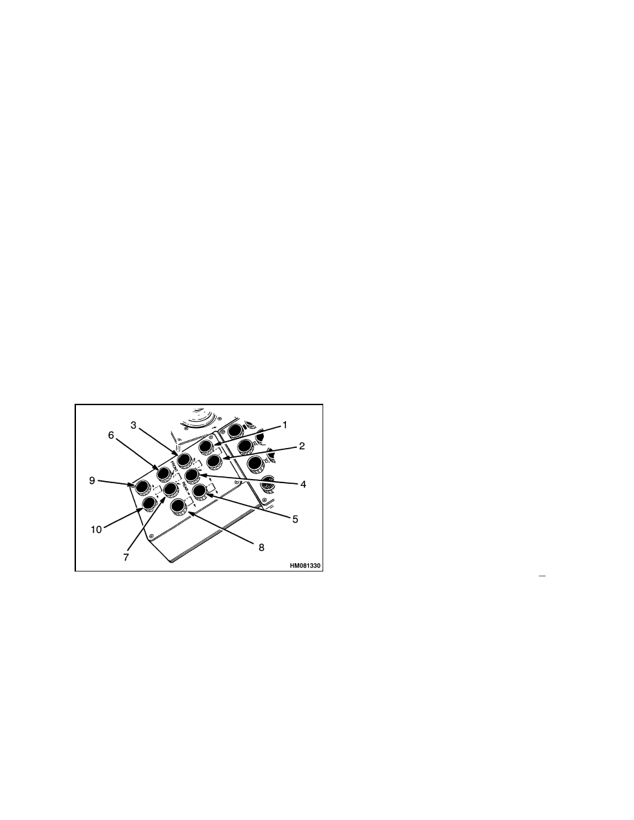
INTERMODAL CONTROL SWITCHES
There are 10 round buttons in four rows on the inter-
modal control panel. See Figure 8. Theses switches
are all push button switches (push and release). First
row left, moves the front legs to the open position.
First row center, moves the rear legs to the open po-
sition. Second row left, moves front legs up. Second
row center, moves rear legs up. Second row right,
opens the block stacking legs. Third row left, moves
front legs down. Third row center, moves rear legs
down. Third row right, closes block stacking legs.
Fourth row left, moves front legs closed. Fourth row
center, moves rear legs closed.
1.
FRONT LEGS OPEN
2.
REAR LEGS OPEN
3.
FRONT LEGS UP
4.
REAR LEGS UP
5.
BLOCK STACKING CLOSED
6.
FRONT LEGS DOWN
7.
REAR LEGS DOWN
8.
BLOCK STACKING CLOSED
9.
FRONT LEGS CLOSE
10. REAR LEGS CLOSE
Figure 8. Intermodal Panel
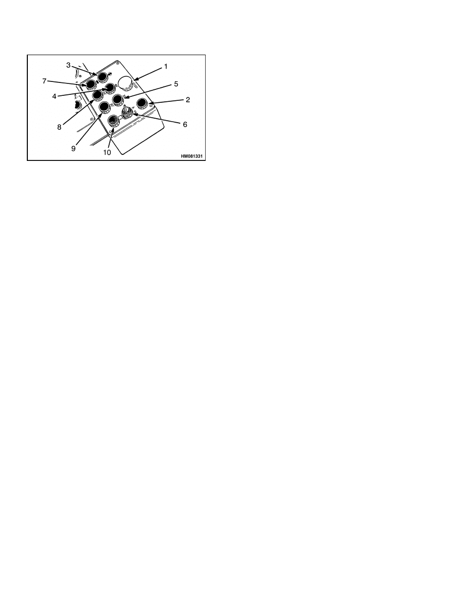
SPREADER CONTROL SWITCHES
There are nine round buttons and a key switch
in three rows on the spreader control panel. See
Figure 9. First row center, stops all action of the
spreader. First row right, overrides the lockout of
boom hydraulics when the twist locks malfunction.
This switch is only used when the AUTO/MAN-
UAL switch is in the MANUAL position.
The
AUTO/MANUAL switch also disengages the twist
lock AUTO-LOCK feature in the MANUAL posi-
tion. Second row left, rotates the twist locks to the
engaged position. Second row left center, sets the
spreader to the 40-foot length for operation with
40-foot containers.
Second row right center, sets
the spreader to the 35-foot length for operation with
35-foot containers. Second row right (key switch),
in the A (left) position, sets the spreader beams to
automatically move to the container length set by
the selector buttons. In the M (right) position, sets
the spreader beams for manual operation to the
correct length. Third row left, rotates the twist locks
to the release position. Third row left center, sets
the spreader to the 20-foot length for operation with
20-foot containers. Third row right center, sets the
spreader to the 30-foot length for operation with
30-foot containers. Third row right, allows the op-
erator to override the ±12 degree spreader rotation
stops for additional rotation between
95 degrees
and +185 degrees.
11
Electrical Control System
2200 SRM 647
1.
EMERGENCY STOP SWITCH FOR SPREADER
2.
OVERRIDE BUTTON FOR BOOM LIFT LOCK
3.
TWIST LOCK ENGAGE
4.
40-FOOT SELECTOR
5.
35-FOOT SELECTOR
6.
SPREADER AUTO/MANUAL SWITCH
7.
TWIST LOCK RELEASE
8.
20-FOOT SELECTOR
9.
30-FOOT SELECTOR
10. ROTATE OVERRIDE
Figure 9. Spreader Control Panel
SWITCH REPLACEMENT ON CONTROL
PANELS
NOTE: Switches do not normally malfunction. Make
sure the circuit breaker and relay operate correctly
before replacing a switch.
Disconnect the power. Make sure the key is in the
OFF position. Remove the plate of the control panel.
Attach labels to the switch wires for correct connec-
tion to the new switch. Remove the wires from the
switch, then remove the switch from the plate. In-
stall the new switch and connect the wires accord-
ing to the wire labels. Install the plate of the control
panel.
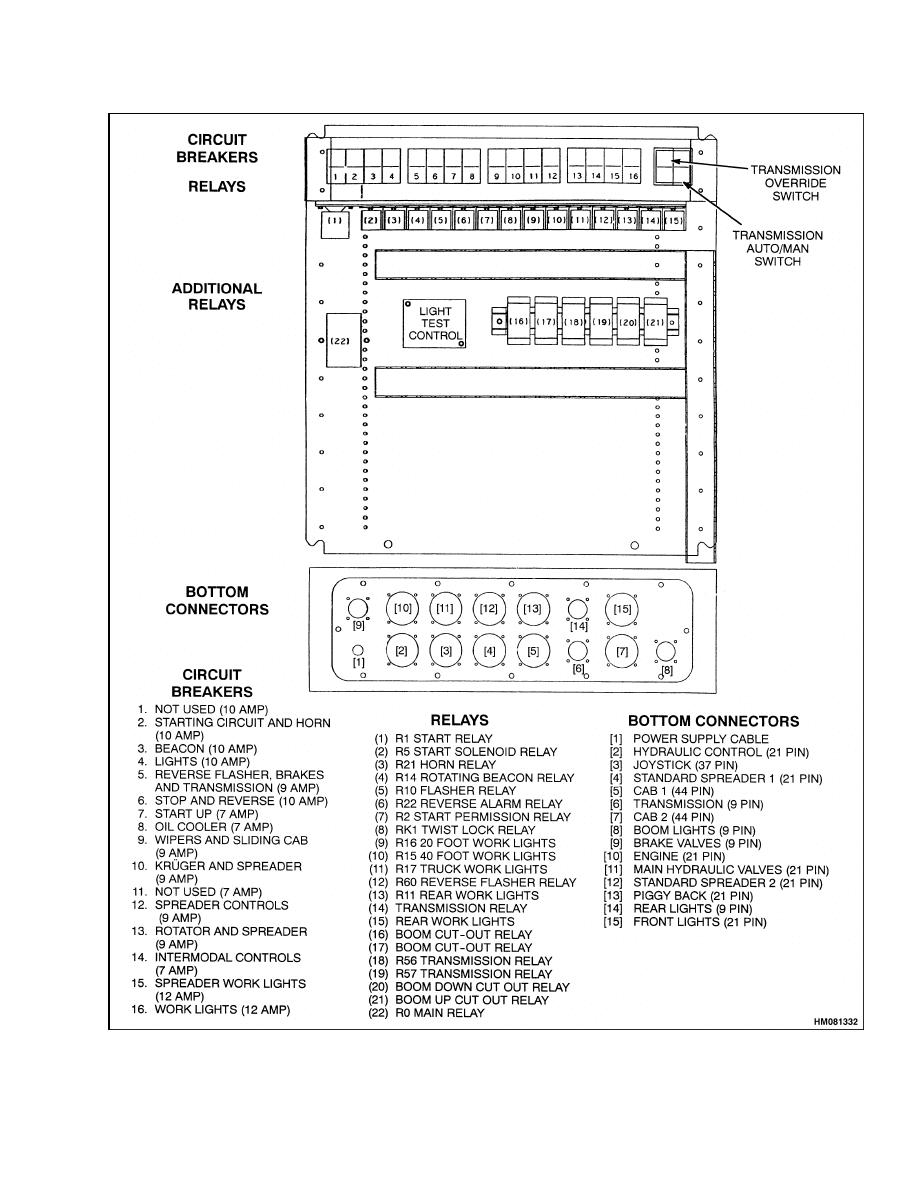
CONTROL BOX COMPONENTS
All of the relays and flasher relays in the control box
plug into sockets. See Figure 10. These relays cannot
be repaired and must be replaced if they malfunction.
Always make sure the socket pins and wires to the
socket pins are not damaged before replacing a relay.
Make sure the relay is fully inserted into the socket.
12
2200 SRM 647
Electrical Control System
Figure 10. Electrical Control Box
13

Troubleshooting
2200 SRM 647
Kruger Electrical System
This electrical system prevents lifting loads that are
over capacity as well as preventing moving the load
over the operator compartment. The system has a
small computer using inputs from pressure sensors
in the lift circuit to determine the weight of the con-
tainer.
NOTE: See the section Troubleshooting and
Adjustments, For Mark 3E/2 Load Sensing Sys-
tems 1900 SRM 642 for information on the Kruger
electrical system.
Troubleshooting
PROBLEM
POSSIBLE CAUSE
PROCEDURE OR ACTION
STARTING SYSTEM
Starter does not run or has
slow speed.
The batteries are not fully charged or
are damaged.
Recharge or replace battery
The power disconnect switch is in the
Off position.
Place power disconnect switch in the
On position.
The connections at the batteries or
starter are loose or corroded.
Tighten connections to battery or
starter. Remove corrosion.
Key switch is damaged.
Replace key switch
Start switch is damaged or circuit
breaker is open.
Replace start switch or close circuit
breaker.
Start relay is damaged.
Replace start relay.
Solenoid coil or switch contacts are
damaged.
Repair or replace solenoid coil or
switch contacts.
Brush springs in starter are dam-
aged.
Replace brush springs.
Brush leads are broken or have a
short circuit.
Replace brush leads or repair short
circuit.
Commutator in starter is dirty or
worn.
Clean or replace commutator
Armature winding in starter is dam-
aged.
Repair or replace winding.
Field windings in starter are dam-
aged.
Repair or replace field windings
Worn or damaged starter gears.
Replace starter gears
Bearings in starter are worn or dam-
aged.
Replace bearings.
14

2200 SRM 647
Troubleshooting
PROBLEM
POSSIBLE CAUSE
PROCEDURE OR ACTION
Starter operates, but engine
crankshaft does not rotate.
Wiring
connections
are
broken,
loose, or have corrosion.
Replace or tighten wiring connec-
tions. Remove corrosion.
Starter clutch assembly is damaged.
Repair or replace starter clutch as-
sembly.
Solenoid is damaged and will not
keep the clutch assembly engaged.
Repair or replace solenoid.
Starter clutch assembly will not
move freely.
Repair or replace starter.
Gear teeth on starter clutch assem-
bly are damaged.
Replace gear teeth.
Gear teeth on ring gear are damaged.
Replace gear teeth.
Starter continues to run.
Contacts of solenoid are welded to-
gether.
Repair or replace solenoid.
Solenoid coil has a short circuit.
Replace solenoid.
Spring that disengages the starter
clutch is broken.
Replace spring.
Key switch is damaged.
Replace key switch.
CHARGING SYSTEM
Batteries
do
not
stay
charged.
Battery terminals have corrosion.
Clean battery terminals to remove
corrosion.
A battery has damage inside the
case.
Replace battery.
Drive belt for alternator is loose.
Tighten drive belt.
Wiring
connections
are
broken,
loose, or have corrosion.
Replace or tighten wiring connec-
tions. Remove corrosion.
Short circuit between wiring connec-
tor(s).
Repair or replace wiring connectors.
Alternator brushes are worn.
Replace brushes.
Alternator
brushes
have
weak
springs.
Replace springs.
Alternator has dirty slip rings.
Clean or replace slip rings.
15

Troubleshooting
2200 SRM 647
PROBLEM
POSSIBLE CAUSE
PROCEDURE OR ACTION
Batteries
do
not
stay
charged. (Cont.)
Stator coil for alternator has a short
circuit.
Replace stator coil.
Voltage regulator is damaged.
Replace voltage regulator.
Batteries are charged more
than necessary.
Wiring
connections
are
broken,
loose, or corroded.
Replace or tighten wiring connec-
tions. Remove corrosion.
Short circuit between wiring connec-
tor(s).
Repair or replace wiring connectors.
Field coil in alternator is damaged.
Repair or replace alternator.
Regulator in alternator is damaged.
Repair or replace alternator.
High resistance in the circuit.
Repair or replace parts.
Batteries uses more water
than normal.
Batteries are being charged more
than normal.
Replace voltage regulator.
Alternator is damaged stator wind-
ings, diodes, rectifier bridge, rotor, or
voltage regulator.
Repair or replace parts.
Battery or batteries are damaged.
Replace battery or batteries.
There is no charge from the
alternator.
The indicator
light indicates a discharge
condition when the rpm is
high and the load is high.
Alternator drive belt is not tight or is
broken.
Tighten alternator belt or replace.
Alternator brushes are worn or dam-
aged.
Replace or repair alternator brushes.
Weak
alternator
brush
springs.
Brushes do not move freely in the
brush holders.
Repair or replace brush springs.
Dirt on the alternator slip rings.
Clean slip rings.
Discharge
indicator
indi-
cates a discharge condition
at all engine speeds.
There is an electrical ground in the
field winding.
Repair or replace field winding.
There is a short circuit in the alter-
nator diodes.
Repair or replace alternator.
16

2200 SRM 647
Troubleshooting
PROBLEM
POSSIBLE CAUSE
PROCEDURE OR ACTION
Discharge
indicator
indi-
cates a discharge condition
at all engine speeds. (Cont.)
There is an electrical ground at the
end of the alternator windings.
Repair or replace alternator.
The voltage regulator has damage.
Replace voltage regulator.
ELECTRICAL SYSTEM
All indicator lights are out.
Fuse(s) are damaged.
Replace fuses.
Connector at attachment is discon-
nected or damaged.
Reconnect or repair connector.
Wiring harness on attachment is
damaged.
Replace or repair wiring harness.
Wiring harness to operator compart-
ment is disconnected or damaged.
Reconnect or repair wiring harness.
Amber light is out.
Switch or switches at interlock
valve(s) or twist lock cylinders are
damaged or not adjusted correctly.
Adjust or replace switches.
Bulb(s) are damaged. Wires are dis-
connected.
Reconnect wires or replace bulb(s).
Green light is out.
Switch or switches at interlock
valve(s) are damaged or not adjusted
correctly.
Adjust or replace switches.
Bulb(s) are damaged. Wires are dis-
connected.
Reconnect wires or replace bulb(s).
Blue light is out.
Switch or switches at interlock
valve(s) or twist lock cylinders are
damaged or not adjusted correctly.
Adjust or replace switches.
Bulb(s) are damaged. Wires are dis-
connected.
Reconnect wires or replace bulb(s).
Indicator lights stay on.
Switches at twist lock cylinders or in-
terlock valves are damaged or not ad-
justed correctly.
Adjust or replace switches.
17

Troubleshooting
2200 SRM 647
PROBLEM
POSSIBLE CAUSE
PROCEDURE OR ACTION
Hydraulic
function
does
not operate when button is
pushed.
Push button switches, relays, or cir-
cuit breakers for the function have a
malfunction or are damaged.
Repair
or
replace
push
button
switches, relays, or circuit break-
ers.
Hydraulic component has a mal-
function or is damaged.
See the
section Hydraulic System 1900
SRM 641, Container Attachment,
ReachStacker 4500 SRM 648, or
the section Boom 4500 SRM 649.
Repair or replace hydraulic compo-
nent.
Hydraulic
function
does
not operate when handle is
moved.
Joystick, relays, or circuit breakers
for the function have a malfunction
or are damaged.
Replace or repair joystick, relays, or
circuit breakers.
Hydraulic component has a mal-
function or is damaged.
See the
section Hydraulic System 1900
SRM 641, Container Attachment,
ReachStacker 4500 SRM 648, or
the section Boom 4500 SRM 649.
Repair or replace hydraulic compo-
nent.
18


TECHNICAL PUBLICATIONS
2200 SRM 647
3/05 (1/98) Printed in United Kingdom
Document Outline
- toc
Wyszukiwarka
Podobne podstrony:
1586985 2200SRM1178 (03 2005) UK EN
1589731 2200SRM1184 (03 2005) UK EN
897825 2200SRM0596 (03 2005) UK EN
897953 1600SRM0639 (03 2005) UK EN
1598459 1900SRM1213 (03 2005) UK EN
897956 1900SRM0642 (03 2005) UK EN
897963 4500SRM0649 (03 2005) UK EN
897435 2200SRM0473 (03 1994) UK EN
1554634 2200SRM1078 (07 2005) UK EN
1573930 0600SRM1172 (03 2005) UK EN
897345 1400SRM0413 (03 2005) UK EN
1531815 1800SRM1040 (03 2005) UK EN
1468474 2200SRM0756 (07 2005) UK EN
899782 2000SRM0077 (03 2005) UK EN
więcej podobnych podstron