INSTRUMENT PANEL
INDICATORS AND
SENDERS
H3.50-5.50XM (H70-120XM) [K005, L005];
S3.50-5.50XM (S70-120XM) [E004, F004]
PART NO. 1468474
2200 SRM 756

SAFETY PRECAUTIONS
MAINTENANCE AND REPAIR
• When lifting parts or assemblies, make sure all slings, chains, or cables are correctly
fastened, and that the load being lifted is balanced. Make sure the crane, cables, and
chains have the capacity to support the weight of the load.
• Do not lift heavy parts by hand, use a lifting mechanism.
• Wear safety glasses.
• DISCONNECT THE BATTERY CONNECTOR before doing any maintenance or repair
on electric lift trucks. Disconnect the battery ground cable on internal combustion lift
trucks.
• Always use correct blocks to prevent the unit from rolling or falling. See HOW TO PUT
THE LIFT TRUCK ON BLOCKS in the Operating Manual or the Periodic Mainte-
nance section.
• Keep the unit clean and the working area clean and orderly.
• Use the correct tools for the job.
• Keep the tools clean and in good condition.
• Always use HYSTER APPROVED parts when making repairs. Replacement parts
must meet or exceed the specifications of the original equipment manufacturer.
• Make sure all nuts, bolts, snap rings, and other fastening devices are removed before
using force to remove parts.
• Always fasten a DO NOT OPERATE tag to the controls of the unit when making repairs,
or if the unit needs repairs.
• Be sure to follow the WARNING and CAUTION notes in the instructions.
• Gasoline, Liquid Petroleum Gas (LPG), Compressed Natural Gas (CNG), and Diesel fuel
are flammable. Be sure to follow the necessary safety precautions when handling these
fuels and when working on these fuel systems.
• Batteries generate flammable gas when they are being charged. Keep fire and sparks
away from the area. Make sure the area is well ventilated.
NOTE: The following symbols and words indicate safety information in this
manual:
WARNING
Indicates a condition that can cause immediate death or injury!
CAUTION
Indicates a condition that can cause property damage!
Instrument Panel Indicators and Senders
Table of Contents
TABLE OF CONTENTS
General ...............................................................................................................................................................
Description .........................................................................................................................................................
Instruments and Senders..............................................................................................................................
Password Function ........................................................................................................................................
Supervisor Password Function .................................................................................................................
Entering Operator Passwords ..............................................................................................................
Deleting Operator Passwords...............................................................................................................
Retrieve the Most Recent Operator Password Used to Enable the Truck .........................................
Display All Operator Passwords Programmed Into the System ........................................................
Enable and Disable Operator Passwords Function ............................................................................
Allow Supervisor Password to Enable the Truck to Start ..................................................................
Operator Passwords Function ..................................................................................................................
Component Replacement - General Information .............................................................................................
Sender Replacement ..........................................................................................................................................
Fuel Level Sender ..........................................................................................................................................
Pressure and Temperature Sender ...............................................................................................................
Display Panel Replacement...............................................................................................................................
Specifications......................................................................................................................................................
Troubleshooting..................................................................................................................................................
This section is for the following models:
H3.50-5.50XM (H70-120XM) [K005, L005];
S3.50-5.50XM (S70-120XM) [E004, F004]
©2005 HYSTER COMPANY
i

"THE
QUALITY
KEEPERS"
HYSTER
APPROVED
PARTS
2200 SRM 756
Description
General
The gauges and meters provide information to the op-
erator on the condition of various systems. Gauges
may be either direct reading (mechanical) or indi-
rect (electrical). Unlike mechanical gauges, electri-
cal gauges have electrical meter movements, light
emitting diode (LED), or digital displays inside the
case. These meters receive an electrical signal from
a sender unit, usually in the engine or transmission
case. The indicators of electric lift trucks receive an
electrical signal from a sensor (motor temperature)
or a control board. This section only describes the
electrical gauges, meters, senders, and instrument
panel displays. Gauges will be referred to as meters.
The meters and displays are used to provide operator
information on the status of many systems including:
engine coolant temperature, engine or transmission
oil pressure or temperature, fuel level, battery cur-
rent (ammeter), and battery voltage (voltmeter). See
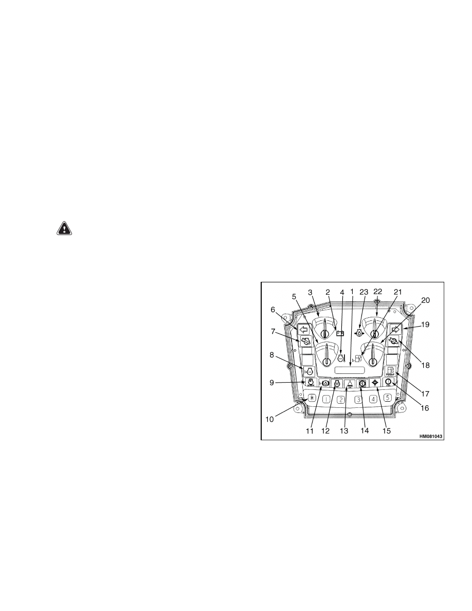
Figure 1.
Description
INSTRUMENTS AND SENDERS
WARNING
If any of the instruments do not operate as de-
scribed, report the problem immediately. DO
NOT operate the lift truck until the problem is
corrected.
Many meters have meter movements that move an
indicating needle attached to a shaft or pin. The
shaft rotates to swing the needle when current flows
through the movement.
The movement operates
on the same electromagnetic principle that causes
a motor shaft to rotate. However, shaft rotation of
a meter is limited to much less than one full revo-
lution. The amount of rotation or deflection of the
needle is directly related to the amount of current
flow through the meter movement. Meter faces are
calibrated to indicate a range of values that are
converted from a directly proportional current flow
through the sender. For examples of meter faces and
indicators, see Figure 1 and Table 1.
Meters such as voltmeters and the hourmeter are
able to convert this proportional current within the
meter case. Other meters and displays require a sep-
arate sender. See Table 2. Senders convert a specific
pressure, temperature, or fluid level into a current
flow that is directly related to a given voltage (elec-
trical system voltage) applied.
The display panel has a password function that per-
mits operation of the lift truck. The lift truck cannot
be started without first entering the password code.
The password function can be disabled by the super-
visor.
Figure 1. Instrument Cluster
1
Description
2200 SRM 756
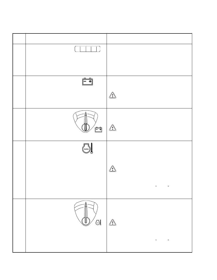
Table 1. Instrument Panel Description
Item
No.
Item
Function
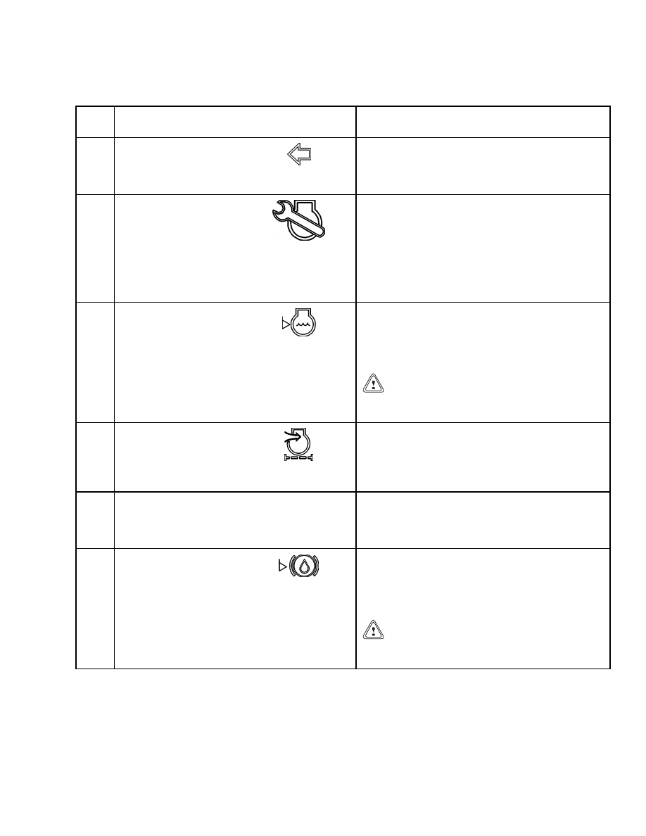
1
Hourmeter
The hourmeter on the instrument panel displays
the number of operating hours of the truck. The
meter displays the operating time of 0000 to
999,999.9 hours. The hourmeter operates when
the key switch is in the ON position. Periodic
Maintenance recommendations are based on
these hours.
2
Warning Light,
Alternator
The light will be on when the key switch is ON
and the engine is not running. The light must go
off when the engine is running.
CAUTION
Do not continue to operate the lift truck if the
red light is on at engine speeds above idle.
3
Voltmeter
This gauge indicates the output of the alternator.
During normal operation the gauge needle will be
in the green area.
CAUTION
Do not continue to operate the lift truck
when the gauge needle is in the red area.
4
Indicator Light, Coolant
Temperature
The light will be on when the key switch is ON
and the engine is not running. If this light comes
on while the engine is running, this indicates the
engine coolant has overheated. The light must go
off when the engine is running.
CAUTION
Do not continue to operate the lift truck if the
red light is on during operation.
NOTE: Engine will stop after a 30-second warning
buzzer if coolant is over 121 C (250 F). When en-
gine stop occurs, the hourmeter display will show
the word "Stop."
5
Coolant Temperature
Gauge
This gauge indicates engine coolant temperature
when the key switch is in the ON position. During
normal operation the gauge needle will be in the
green area.
CAUTION
Do not continue to operate the lift truck if the
red light is on during operation.
NOTE: Engine will stop after a 30-second warning
buzzer if coolant is over 121 C (250 F). When en-
gine stop occurs, the hourmeter display will show
the word "Stop."
2
2200 SRM 756
Description
Table 1. Instrument Panel Description (Continued)
Item
No.
Item
Function
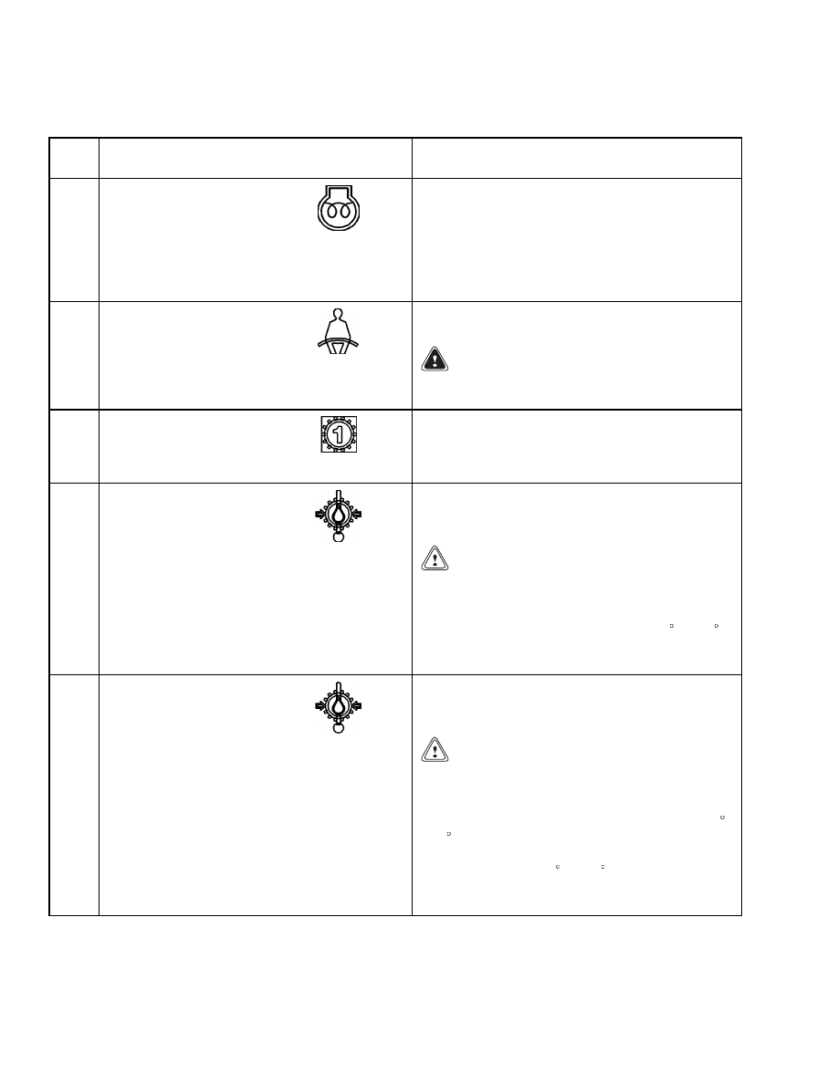
6
Indicator Light,
Left-Hand Turn,
H3.50-5.50XM
(H70-120XM)
The light is on when the turn indicator lever is
in the left turn position.
7
Indicator Light, Service
Engine Soon
(Lift Trucks with
GM 4.3L Engine and
Gas/LPG Fuel System)
This light will be on when the key switch is ON
and the engine is not running. This light will
illuminate when the ECM computer senses a fault
in the operation of the engine. If the engine starts,
the operation of the engine will not be correct
until the fault is corrected. A trained service
person must make repairs and adjustments if this
light is on when the engine is running.
8
Warning Light, Coolant
Level in the Radiator
The red light is on when the key switch is in the
START position and must go off when the engine
is running. If the light is on when the engine is
running, the level of the coolant in the radiator
is too low.
CAUTION
Do not continue to operate the lift truck if the
light is on during operation.
9
Indicator Light, Air
Filter Restriction
The red light is on when the key switch is in the
START position and must go off when the engine
is running. If the light is on when the engine is
running, the air cleaner has a restriction and
needs cleaning.
10
Operator Password Function
This system will only allow an operator whose
password is preprogrammed in the system
to operate the lift truck. Refer to Operator
Passwords Function for more information.
11
Warning Light, Brake
Fluid Level
The red light is on when the key switch is in the
START position and must go off when the engine
is running. If the light is on when the engine is
running, the brake fluid level in the reservoir is
too low.
CAUTION
Do not continue to operate the lift truck if the
light is on during operation.
3
Description
2200 SRM 756
Table 1. Instrument Panel Description (Continued)
Item
No.
Item
Function
12
Indicator Light, Cold
Start (Diesel Only)
The red light is on when the key switch is ON and
the glow plug dash button is pressed. The length
of time the glow plugs are activated is determined
by the temperature of the engine. When the light
goes out, the engine can be started. When the
starter is cranking, the light will come on again
until the starter is off and the engine is running.
13
Warning Light, Fasten
Seat Belt
The red light is on for 10 seconds any time the key
switch is put in the ON position.
WARNING
Always fasten the seat belt when operating
the lift truck.
14
Indicator Light,
Transmission 1st
Gear, H3.50-5.50XM
(H70-120XM)
The light is on when the two-speed transmission
is locked into first gear by activating the
transmission lockout switch on the dash.
15
Warning Light,
Powershift
Transmission Oil
Temperature
The red light is on when the key switch is in the
START position and must go off when the engine
is running.
CAUTION
Do not continue to operate the lift truck if the
red light is on.
NOTE: Engine will stop after a 30-second warn-
ing buzzer if transmission oil is over 132 C (270 F).
When engine stop occurs, the hourmeter display
will show the word "Stop."
15
Warning Light,
Hydrostatic
Transmission Oil
Temperature,
H3.50-5.50XM
(H70-120XM)
The red light is on when the key switch is in the
START position and must go off when the engine
is running.
CAUTION
Do not continue to operate the lift truck if the
red light is on.
NOTE: If the lift truck is equipped with a hydro-
static transmission and the oil temperature is 96 C
(205 F), the warning light flashes, the fault light
flashes an event code, and an alarm sounds. If the
oil temperature is 104 C (220 F) for 30 seconds, the
engine will shut off. When engine stop occurs, the
hourmeter display will show the word "Stop."
4
2200 SRM 756
Description
Table 1. Instrument Panel Description (Continued)
Item
No.
Item
Function
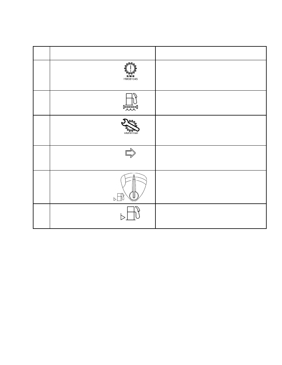
16
Warning Light,
Hydrostatic
Transmission
Overspeed, H3.50-
5.50XM (H70-120XM)
This light indicates a hydrostatic transmission
overspeed condition.
17
Warning Light, Water
Separator (Diesel Only)
The red light is on when the key switch is in the
START position and must go off when the engine
is running. If the light is on when the engine is
running, the water separator must be drained.
18
Warning Light,
Hydrostatic
Transmission Fault,
H3.50-5.50XM
(H70-120XM)
This light indicates a fault in the hydrostatic
transmission control system. This light is
also used to signal fault code numbers during
troubleshooting.
19
Indicator Light,
Right-Hand Turn,
H3.50-5.50XM
(H70-120XM)
The light is on when the turn indicator lever is in
the right turn position.
20
Fuel Gauge
This gauge indicates the amount of fuel in the
gasoline or diesel fuel tank. This gauge is not
available on the LPG truck.
When engine stop occurs, the hourmeter display
will show the word "Stop."
21
Indicator Light, Fuel
Level
This indicator light will come on when the fuel
level is low.
When engine stop occurs, the hourmeter display
will show the word "Stop."
5
Description
2200 SRM 756
Table 1. Instrument Panel Description (Continued)
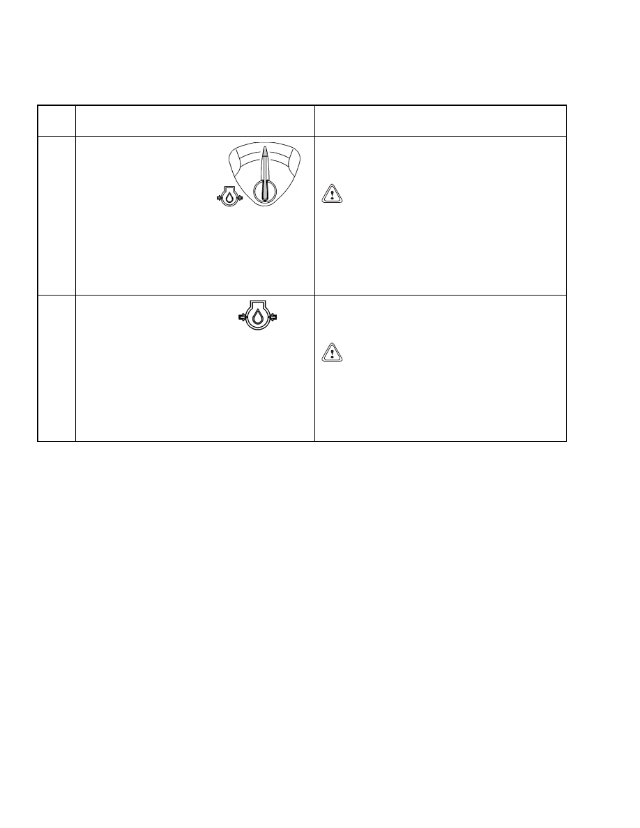
Item
No.
Item
Function
22
Engine Oil Pressure
Gauge
This gauge indicates the pressure of the oil in
the engine. During normal operation the gauge
needle will be in the green area.
CAUTION
Do not continue to operate the lift truck
when the gauge indicates low oil pressure
(needle in the red area).
NOTE: Engine will stop after a 30-second warning
buzzer if engine oil pressure is less than 13.8 kPa
(2 psi). When engine stop occurs, the hourmeter
display will show the word "Stop."
23
Warning Light, Engine
Oil Pressure
The red light is on when the key switch is in the
ON position and must go off when the engine is
running.
CAUTION
Stop the engine immediately if the red light
is on while the engine is running.
NOTE: Engine will stop after a 30-second warning
buzzer if engine oil pressure is less than 13.8 kPa
(2 psi). When engine stop occurs, the hourmeter
display will show the word "Stop."
6
2200 SRM 756
Description
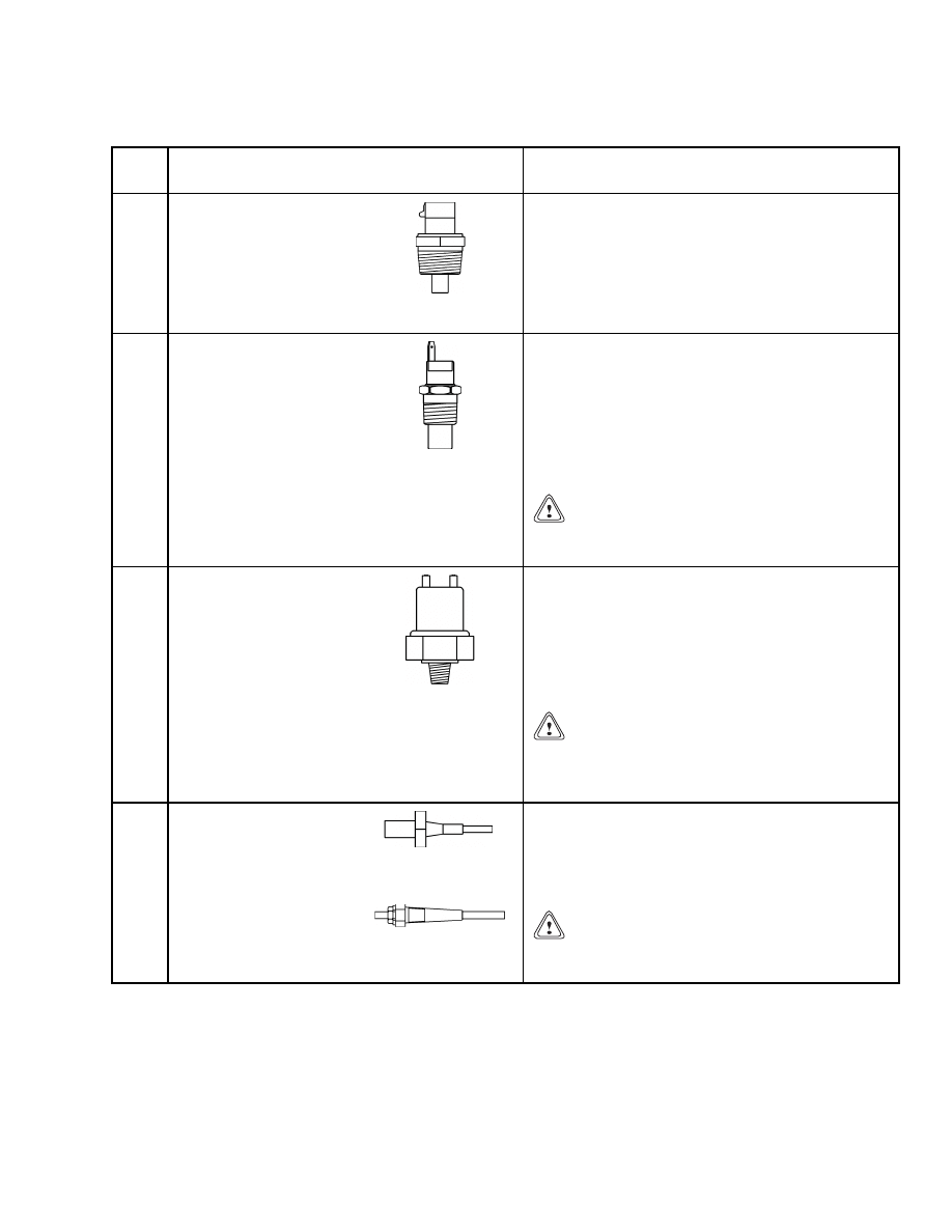
Table 2. Sender Description
Item
No.
Item
Function
1
Water Temperature
Sender
The water temperature sender is mounted in the
engine block and senses the water temperature.
If the water temperature exceeds the specified
temperature, the sender sends a signal to the
control panel and lights the coolant temperature
indicator. This signal also drives the coolant
temperature gauge. See Table 3.
2
Transmission
Temperature Sender
The transmission temperature sender unit is
mounted in the front of the transmission and
senses the transmission fluid temperature and
pressure. When the transmission temperature or
pressure exceeds system specifications, the sender
sends a signal to the control panel and lights the
transmission pressure/temperature indicator. See
Table 3.
CAUTION
Do not continue to operate the lift truck if the
red light is on at engine speeds above idle.
3
Oil Pressure Sender
The oil pressure sender is located on the side
of the engine block and senses the engine oil
pressure. If the pressure exceeds the upper or
lower pressure specifications, the sender sends a
signal to the control panel and lights the engine oil
pressure indicator. The oil pressure sender signal
also drives the oil pressure meter. See Table 3.
CAUTION
Do not continue to operate the lift truck
when the gauge indicates in the red areas of
the gauge.
4
Low Coolant Sender
H3.50-5.50XM
(H70-120XM)
S3.50-5.50XM
(S70-120XM)
The low coolant sender is mounted in the coolant
system radiator near the top of the tank. It senses
the fluid level and, when low, sends a signal to the
control panel and lights the coolant system fluid
low warning indicator.
CAUTION
Do not continue to operate the lift truck if the
red light is on during operation.
7
Description
2200 SRM 756
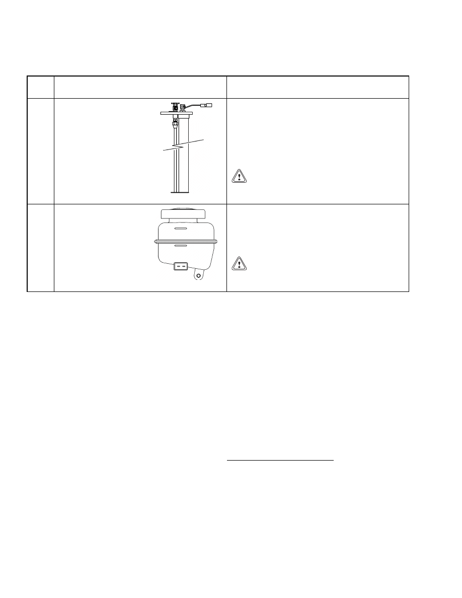
Table 2. Sender Description (Continued)
Item
No.
Item
Function
5
Fuel Level Sender
The fuel level sender is installed in the fuel
tank and indicates when the fuel is low. An
internal float closes the circuit, sends a signal to
the control panel, and lights the fuel level low
warning indicator. A signal is also sent to the
fuel level gauge to indicate the amount of fuel
remaining in the tank.
CAUTION
Do not continue to operate the lift truck if the
red light is on during operation.
6
Brake Fluid Sender
The low brake fluid level sender is built into the
brake fluid reservoir. When the brake fluid is low,
the float inside the reservoir closes the circuit,
sends a signal to the control panel, and lights the
brake fluid low warning indicator.
CAUTION
Do not continue to operate the lift truck if the
red light is on during operation.
PASSWORD FUNCTION
When enabled, the Operator Passwords Function al-
lows only supervisors and operators, whose five-digit
password has been preprogrammed in the system,
the capability to start the lift truck engine. The su-
pervisor password and the operator password pro-
vide different levels of access. The following sections
describe functions available at Supervisor and Oper-
ator levels of access.
Supervisor Password Function
NOTE: The five-digit supervisor’s access password is
provided at lift truck delivery and is included on a
removable label on the bottom of the display panel. If
the access password is lost, contact your dealer and
provide them with the display panel serial number
and manufacturing date. See the section, Display
Panel Replacement and Figure 5.
The supervisor password, when entered, allows ac-
cess to the following:
• Enabling and disabling the operator passwords
function. (5)
• Entering operator passwords. (1)
• Deleting operator passwords. (2)
• Retrieving the most recent operator password that
enabled the truck to start. (3)
• Displaying all operator passwords programmed
into the system. (4)
• Allowing the supervisor password to be used to en-
able the truck to start. (
*
)
Input is from a six-key membrane pad labeled
*
and
1 through 5. The
*
key serves to execute a function
or exit supervisor mode. Supervisor access mode will
also time out, and the display will return to showing
hours when no keys are pressed for 10 seconds. If a
mistake is made during any password entry, re-enter
the password before pressing the
*
key. Only the
last 5 numbers entered will be used when processing
passwords.
Entering Operator Passwords
1.
Enter supervisor password and press
*
key.
2.
Press the 1 key and then press
*
key.
3.
Enter a five-digit operator password and press
*
key. The display will show "Enter" if the pass-
word was accepted or "Full" if there are more
than 100 passwords already programmed.
8

2200 SRM 756
Description
4.
Continue to enter additional operator passwords
as in Step 3 or press
*
key again to exit supervi-
sor mode.
Deleting Operator Passwords
1.
Enter supervisor password and press
*
key.
2.
Press the 2 key and then press
*
key.
3.
Enter five-digit operator password and press
*
key. The display will show "Clear" if the pass-
word was deleted or "Error" if the password was
not programmed into the system.
4.
Continue to enter additional operator passwords
as in Step 3 or press
*
key again to exit supervi-
sor mode.
Retrieve the Most Recent Operator Password Used
to Enable the Truck
1.
Enter supervisor password and press
*
key.
2.
Press the 3 key and then press
*
key.
3.
The display will show the most recent password
used to enable the truck.
4.
Press
*
key to exit supervisor mode.
Display All Operator Passwords Programmed Into
the System
1.
Enter supervisor password and press
*
key.
2.
Press the 4 key and then press
*
key.
3.
The display will show the first operator password
in the list.
4.
Press the 4 key again to scroll through list. For
each press of the 4 key, the next password will be
displayed.
5.
When the end of the list is reached, the last pass-
word will remain on display for an additional
press of the 4 key.
6.
Press
*
to exit supervisor mode.
Enable and Disable Operator Passwords Function
1.
Enter supervisor password and press
*
key.
2.
Press the 5 key and then press
*
key.
3.
The 5 key may be pressed again to toggle the
mode the password function will latch into when
the
*
key is pressed. Each time the 5 key is
pressed, the display will toggle between "Loc"
(enabled) and "Start" (disabled).
This shows
which mode the password function will latch
into when the
*
key is pressed.
4.
Press
*
key again to latch password operation
enabled if display is showing "Loc" or disabled
if display is showing "Start." If the
*
key is not
pressed before the 10 second key, press timeout,
the selected password mode will not be changed.
5.
After enabling or disabling this function, turn
key switch OFF for at least 10 seconds.
Allow Supervisor Password to Enable the Truck
to Start
1.
Enter supervisor password and press
*
key.
2.
Press
*
key again without pressing any of the
number keys.
3.
The display will show "Start" and the truck en-
gine will be enabled to start. This enable period
also continues for 5 minutes after the key switch
is turned OFF. If the
*
key is pressed three times
in succession with the key OFF, this enable pe-
riod is reduced to 30 seconds.
Operator Passwords Function
When enabled, the operator passwords function al-
lows only operators, whose 5-digit password has been
preprogrammed in the system, to start the lift truck
engine. Operational instructions for the Operator
Password Function follow:
1.
Input is from a six-key membrane pad labeled
*
and 1 through 5.
2.
The
*
key acts as an enter key to process the
password that has been entered. If the
*
key
is not pressed within 10 seconds of the last key-
press, password entry will not be processed.
3.
If a mistake is made during password entry,
re-enter password before pressing
*
key. Only
the last 5 numbers entered will be used when
processing the password.
4.
If an incorrect password is entered, the display
will show "Loc" and inhibit password re-entry for
5 seconds. After the 5-second inhibit, entering
the password may again be attempted.
9

Sender Replacement
2200 SRM 756
5.
When a valid operator password is entered, the
engine is enabled to run. The hourmeter display
will show "Start." This enable period also contin-
ues for 5 minutes after the key switch is turned
off. If the
*
key is pressed three times in suc-
cession with the key off, this enable period is re-
duced to 30 seconds.
Component Replacement - General Information
WARNING
Before replacing any components, fully lower
the mast and tilt it forward until the tips of
the forks touch the ground. This will prevent
the mast from lowering suddenly if the control
lever is accidently moved.
Always disconnect the battery and remove the
key before replacing components.
Remove any jewelry or metal objects from
your fingers, arms, or neck. These items can
accidentally make an electrical connection
and cause an injury.
NOTE: There are two versions of the display panel
used on this line of trucks. On newer display pan-
els, the turn signals are red. On older display panels,
the turn signals are green. Newer display panels and
their components are non-repairable and must be re-
placed with a complete new display unit.
NOTE: On older display panels, none of the electrical
components of this section can be repaired. All bad
components must be replaced.
Meters, display panels, most indicators, and senders
are not repairable items. The most accurate and usu-
ally easiest checks for proper operation of individual
meters, indicators, or senders is direct replacement.
The most common causes of failure are poor connec-
tions, damaged wires, or improper wiring, but not the
meter, indicator, or sender itself. This section only
has the replacement procedures. Before a meter, in-
dicator, sender, or display panel is replaced, make the
following checks:
1.
Check that other meters and electrical circuits
operate correctly.
2.
Check that battery is fully charged and has a
good ground (diesel, gasoline, and LPG units
only), and check that cable terminals are clean
and tight.
3.
Check that wiring and connections to meter, in-
dicator, or sender are tight and in good condition.
Sender Replacement
FUEL LEVEL SENDER
WARNING
All fuel vapors are extremely explosive. Do not
allow sparks or flames around vehicles or fuel
storage and service areas. Make sure there is
no source of open flame or sparks in the vicin-
ity. Use caution to prevent sparks from tools.
The fuel level sending unit is mounted to the fuel
tank surface (usually top surface) with screws
through the sender plate and gasket. See Figure 2.
Correct sender operation and screw hole alignment
can only be obtained with the plate mounted in one
position. Replace the sender as follows:
1.
Turn key switch to OFF position and disconnect
positive battery cable at battery. Install lock or
tag on connector to prevent connection.
2.
Disconnect sender wire at sender.
10
2200 SRM 756
Sender Replacement
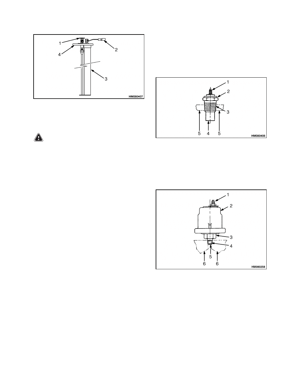
1.
SHUTOFF VALVE
2.
ELECTRICAL
TERMINAL
3.
SENDER UNIT
4.
PLATE
Figure 2. Fuel Level Sender
WARNING
Electrical shock from voltage can cause per-
sonal injury. Put electrical tape on the wire
connector to electrically insulate the connec-
tor if the wire is accidentally energized.
3.
Remove screws that fasten sender plate to fuel
tank. Remove sender.
4.
Carefully install new sender with new gasket.
5.
Make sure screw holes are aligned and install
screws. Tighten screws enough to partially com-
press gasket to prevent leaks.
6.
Remove tape from wire connector. Install connec-
tor on sender terminal.
PRESSURE AND TEMPERATURE SENDER
Pressure senders have a hollow threaded fitting fas-
tened to the base. See Figure 3 and Figure 4. This
makes it possible for the sender to sense the pressure
and also to fasten the sender to the equipment. The
sender can be tightened or loosened using a wrench
on the flats of the hex shape of the fitting. See Ta-
ble 3.The body of the temperature sender has threads
to fit a threaded hole in the equipment. Replace ei-
ther sender as follows:
NOTE: Make sure the system fluid is drained to a
level below the sender to prevent leakage when the
sender is removed.
1.
Turn key switch to OFF position.
2.
Disconnect sender wire.
3.
Turn sender counterclockwise with a wrench un-
til free. Remove and discard old sender.
4.
Install new sender and tighten with a wrench.
5.
Connect sender wire.
1.
ELECTRICAL TERMINAL
2.
HEX
3.
THREADED BODY
4.
SENSOR ELEMENT
5.
CASE OF ENGINE OR TRANSMISSION
Figure 3. Typical Pressure and Temperature
Sender
1.
ELECTRICAL TERMINAL
2.
SENDER
3.
HEX
4.
THREADED FITTING
5.
HOLE-TO-SENSOR ELEMENT
6.
CASE OF ENGINE OR TRANSMISSION
Figure 4. Fluid Pressure Sender
11
Display Panel Replacement
2200 SRM 756
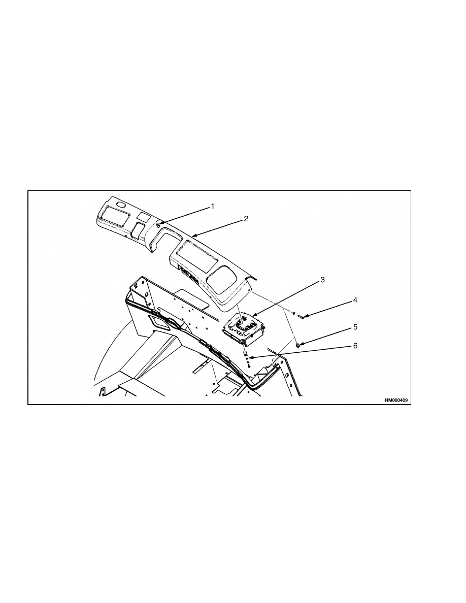
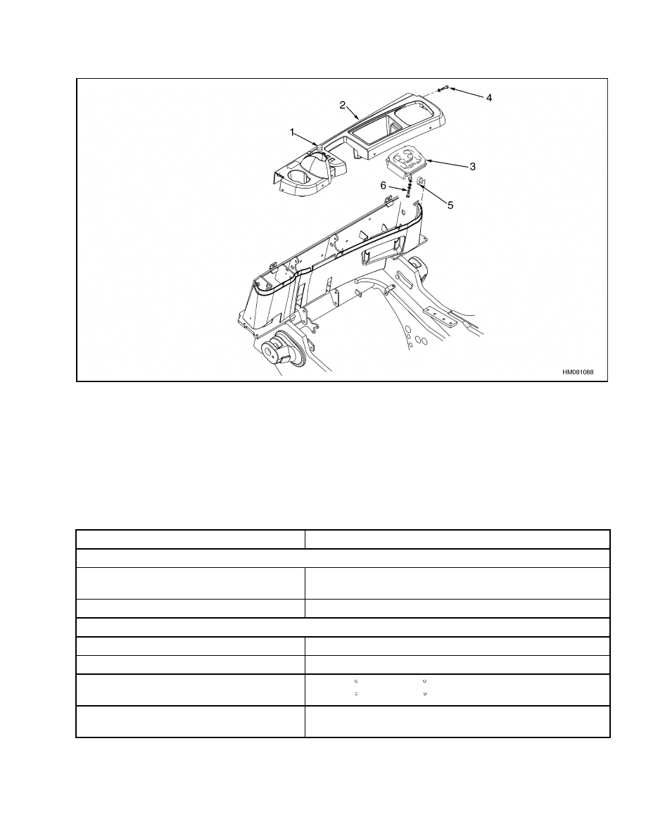
Display Panel Replacement
1.
Disconnect battery and remove key.
2.
Remove dust cover from thermal start switch.
Remove switch from dash. See Figure 5 and Fig-
ure 6.
3.
Remove six screws from dash cover. Lift dash
over parking brake lever.
NOTE: The pigtail on the display panel connector, the
cold start switch, and the soot trap indicator should
be long enough to tilt the dash back far enough to
remove the display panel.
4.
Remove electrical connector from bottom of dis-
play panel.
Remove four screws, washers, and clips that fas-
ten display panel to dash.
6.
Install replacement display panel assembly on
dash and tighten screws. Install electrical con-
nector.
7.
Install dash and tighten six screws that fasten
dash cover.
1.
COLD START SWITCH
2.
DASH
3.
INSTRUMENT PANEL
4.
DASH MOUNTING SCREW (6)
5.
U-NUT (6)
6.
INSTRUMENT PANEL SCREW, WASHER, AND
CLIP (4)
Figure 5. Display Panel Replacement H3.50-5.50XM (H70-120XM)
12
2200 SRM 756
Specifications
1.
COLD START SWITCH
2.
DASH
3.
INSTRUMENT PANEL
4.
DASH MOUNTING SCREW (6)
5.
U-NUT (6)
6.
INSTRUMENT PANEL SCREW, WASHER, AND
CLIP (4)
Figure 6. Display Panel Replacement S3.50-5.50XM (S70-120)
Specifications
Table 3. Meter and Sender Specifications
Item
Design Data
Operating Voltage
Hourmeter (Engine Powered Equipment),
All Other Meters, and Senders
12 V
Sender Terminal Threads
#10-32 UNF or #6-32 UNC
Range of Meter
Hourmeter
0.0 to 999,999.9 Hours
Voltmeter
10 to 16 Volts
Temperature Gauge (Range Based on Re-
quirements)
38 to 121 C (100 to 250 F) Water Temperature
38 to 182 C (100 to 360 F) Transmission Oil Temperature
Oil Pressure Gauge (Range Based on Re-
quirements)
0 to 5.20 kPa (0 to 0.75 psi)
13

Specifications
2200 SRM 756
Table 3. Meter and Sender Specifications (Continued)
Item
Design Data
Fastener Data (To Fit in a Threaded Hole)
Water Temperature Sender (Gauge)
Body Threads
3/8-18 NPTF (GM 4.3L)
1/2-14 NPTF (Diesel)
Hex (Across Flats)
19.0 mm (0.75 in.) (GM 4.3L)
22.0 mm (0.87 in.) (Diesel)
Water Temperature Sender (ECM/ECU)
Body Threads
3/8-18 NPTF (GM 4.3L)
Hex (Across Flats)
19.0 mm (0.75 in.) (GM 4.3L)
Oil Pressure Sender
Fitting Threads
1/8-27 NPTF (GM 4.3L and Diesel)
Hex (Across Flats)
14.0 mm (0.55 in.) (GM 4.3L and Diesel)
Low Coolant Sender
Body Threads
1/2-14 Dryseal
Hex (Across Flats)
23.4 mm (0.92 in.) for a 15/16 in. Wrench
Fuel Sender Plate
Number of Holes
2 (Equally Spaced)
Hole Size
7.30 to 7.60 mm (0.287 to 0.299 in.)
14

2200 SRM 756
Troubleshooting
Troubleshooting
PROBLEM
POSSIBLE CAUSE
PROCEDURE OR ACTION
No Indication - All Meters
Battery disconnected.
Clean the battery terminals and bat-
tery cable connectors. Install connec-
tors.
Battery malfunction or discharged.
Charge or replace battery.
Wiring group connector or connec-
tors not connected.
Fasten connector or connectors.
No Indication - Only One
Meter
Meter wires damaged or not con-
nected.
Replace broken wires or connectors.
Install connectors on proper meter
terminals.
Separate sender wire damaged or
not connected.
Replace broken wire or connector. In-
stall connector on sender terminal.
Meter malfunction. Voltage is at ter-
minal.
Replace meter.
Sender malfunction.
Voltage is at
terminal.
Replace sender.
Incorrect Indication
Battery is discharged.
Charge battery.
Meter movement or needle is dam-
aged or has a malfunction.
Replace meter.
Separate sender malfunction.
Replace sender.
Sender will not sense because sys-
tem has corrosion.
Clean and flush system.
15

NOTES
____________________________________________________________
____________________________________________________________
____________________________________________________________
____________________________________________________________
____________________________________________________________
____________________________________________________________
____________________________________________________________
____________________________________________________________
____________________________________________________________
____________________________________________________________
____________________________________________________________
____________________________________________________________
____________________________________________________________
____________________________________________________________
____________________________________________________________
____________________________________________________________
____________________________________________________________
____________________________________________________________
____________________________________________________________
____________________________________________________________
16


TECHNICAL PUBLICATIONS
2200 SRM 756
7/05 (11/03)(11/01)(8/01)(6/01)(8/99) Printed in United Kingdom
Document Outline
- toc
- Instrument Panel Indicators and Senders
- Safety Precautions Maintenance and Repair
- General
- Description
- Component Replacement - General Information
- Sender Replacement
- Display Panel Replacement
- Specifications
- Troubleshooting
- tables
Wyszukiwarka
Podobne podstrony:
1554634 2200SRM1078 (07 2005) UK EN
1580519 2200SRM1131 (07 2005) UK EN
1534735 2200SRM1056 (07 2005) UK EN
1459370 1600SRM0720 (07 2005) UK EN
1596602 0100SRM1200 (07 2005) UK EN
1586985 2200SRM1178 (03 2005) UK EN
1580518 2200SRM1130 (06 2005) UK EN
897961 2200SRM0647 (03 2005) UK EN
1580521 2200SRM1143 (05 2005) UK EN
1596605 8000SRM1203 (07 2005) UK EN
1534732 0620SRM1053 (07 2005) UK EN
1595265 2200SRM1204 (01 2005) UK EN
1589731 2200SRM1184 (03 2005) UK EN
1534733 1600SRM1054 (07 2005) UK EN
1556364 0620SRM1098 (07 2005) UK EN
więcej podobnych podstron