AC MOTOR REPAIR
J2.00-3.20XM (J40-65Z) [A416]
PART NO. 1534732
620 SRM 1053

SAFETY PRECAUTIONS
MAINTENANCE AND REPAIR
• When lifting parts or assemblies, make sure all slings, chains, or cables are correctly
fastened, and that the load being lifted is balanced. Make sure the crane, cables, and
chains have the capacity to support the weight of the load.
• Do not lift heavy parts by hand, use a lifting mechanism.
• Wear safety glasses.
• DISCONNECT THE BATTERY CONNECTOR before doing any maintenance or repair
on electric lift trucks. Disconnect the battery ground cable on internal combustion lift
trucks.
• Always use correct blocks to prevent the unit from rolling or falling. See HOW TO PUT
THE LIFT TRUCK ON BLOCKS in the Operating Manual or the Periodic Mainte-
nance section.
• Keep the unit clean and the working area clean and orderly.
• Use the correct tools for the job.
• Keep the tools clean and in good condition.
• Always use HYSTER APPROVED parts when making repairs. Replacement parts
must meet or exceed the specifications of the original equipment manufacturer.
• Make sure all nuts, bolts, snap rings, and other fastening devices are removed before
using force to remove parts.
• Always fasten a DO NOT OPERATE tag to the controls of the unit when making repairs,
or if the unit needs repairs.
• Be sure to follow the WARNING and CAUTION notes in the instructions.
• Gasoline, Liquid Petroleum Gas (LPG), Compressed Natural Gas (CNG), and Diesel fuel
are flammable. Be sure to follow the necessary safety precautions when handling these
fuels and when working on these fuel systems.
• Batteries generate flammable gas when they are being charged. Keep fire and sparks
away from the area. Make sure the area is well ventilated.
NOTE: The following symbols and words indicate safety information in this
manual:
WARNING
Indicates a condition that can cause immediate death or injury!
CAUTION
Indicates a condition that can cause property damage!

AC Motor Repair
Table of Contents
TABLE OF CONTENTS
General ...............................................................................................................................................................
AC Motor Repair ................................................................................................................................................
Disassemble ...................................................................................................................................................
Assemble ........................................................................................................................................................
Drive End Bearing, Replace..........................................................................................................................
Troubleshooting..................................................................................................................................................
This section is for the following models:
J2.00-3.20XM (J40-65Z) [A416]
©2005 HYSTER COMPANY
i

"THE
QUALITY
KEEPERS"
HYSTER
APPROVED
PARTS
620 SRM 1053
General
General
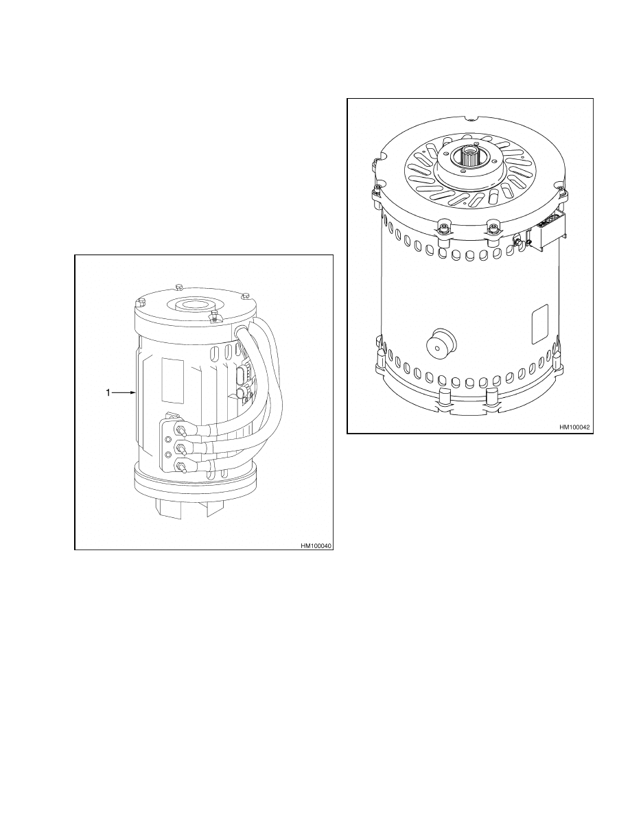
This section describes disassembly and assembly, in-
spection, and checks for malfunctions of AC motors.
AC traction motors and AC hydraulic pump motors
are similar in design. Older model lift trucks are
equipped with an AC traction and AC hydraulic
pump motor that is shown in Figure 1. Newer model
lift trucks are equipped with an AC traction and AC
hydraulic pump motor that is shown in Figure 2.
For both types of motors, the AC hydraulic pump
motor is a smaller version of the AC traction motor.
Disassembly and repair of these motors is similar.
NOTE: AC HYDRAULIC PUMP MOTOR USED ON
OLDER MODEL J2.00-3.20XM (J40-65Z) (A416)
TRUCKS SHOWN.
1.
AC HYDRAULIC PUMP MOTOR
Figure 1. AC Hydraulic Pump Motor (Shown)
NOTE: AC TRACTION MOTOR USED ON NEWER
MODEL J2.00-3.20XM (J40-65Z) (A416) TRUCKS
SHOWN.
Figure 2. AC Traction Motor
1
AC Motor Repair
620 SRM 1053
AC Motor Repair
DISASSEMBLE
WARNING
The bearing and seal on the AC traction motor
are serviceable parts, while the only service-
able part on the AC hydraulic pump motor is
the bearing. Be careful to not damage bearings
when replacing. The AC hydraulic pump motor
weighs 46 kg (101 lb) and the AC traction motor
weighs 109 kg (240 lb). To prevent injury, use a
lifting device capable of lifting the assembly.
NOTE: When replacing one bearing, it is strongly rec-
ommended to replace both bearings and the seal of
the AC traction motor.
1.
Remove motor from the lift truck. See the Frame
SRM for your lift truck model for removal infor-
mation.
2.
Screw lifting eye into the threaded hole in the
end of the rotor shaft and connect a chain to the
lifting eye.
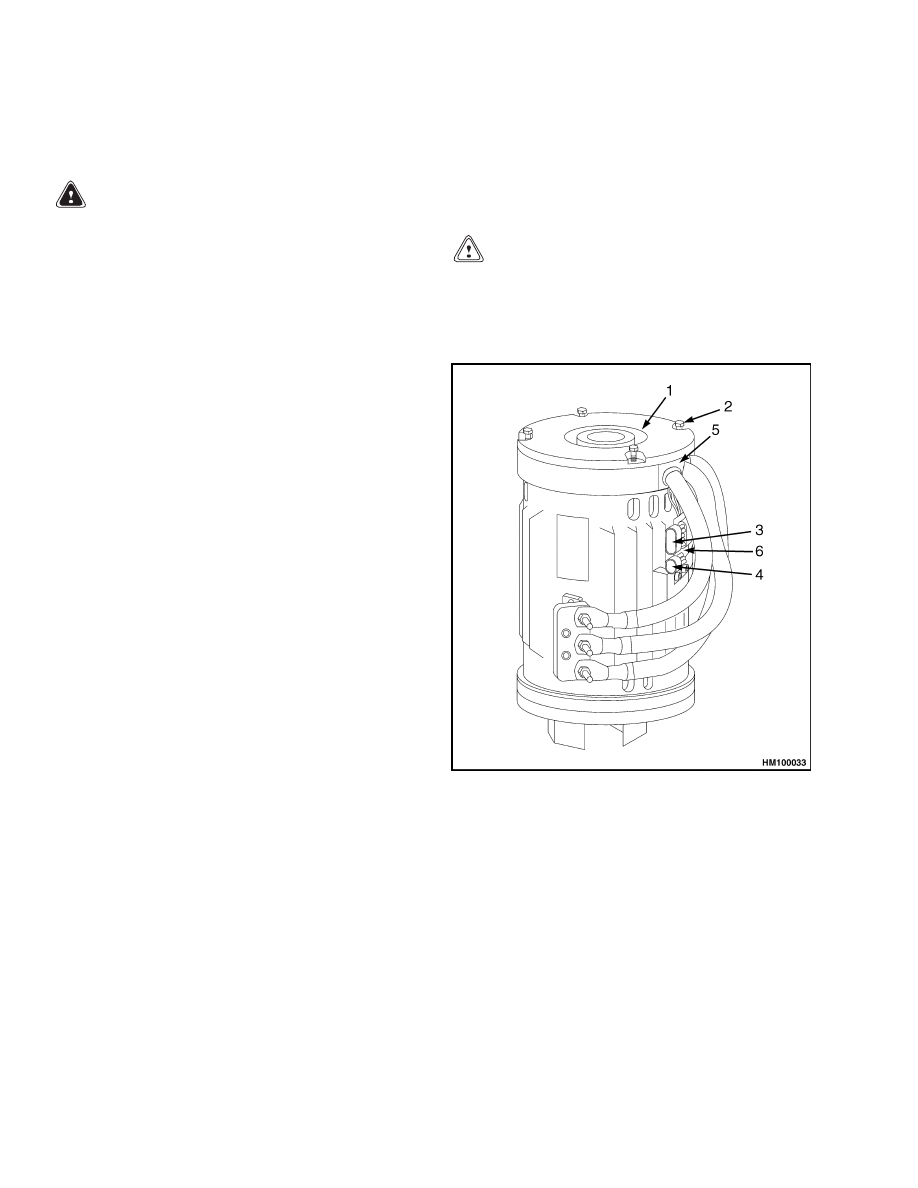
3.
Remove temperature sensor wire and encoder
wire from holding bracket.
See Figure 3 and
Note placement of wires in rubber
gasket that surrounds stator wires.
4.
Remove screws from the nondrive rear end bell.
5.
Place alignment marks on the end bell and motor
case. Marks will be used to correctly align the
end bell on the motor case during assembly.
6.
Lift end bell and rotor assembly from AC motor
case. Place horizontally on a flat surface and re-
move rubber gasket that covers three field wires.
7.
Remove chain and lifting eye.
8.
Remove screws from air guide.
9.
Remove end bell from rotor assembly. See Fig-
ure 5.
10. Remove air guide, being careful not to damage
encoder bearing wire.
NOTE: Before removing the encoder bearing, note its
orientation and install the new encoder bearing in
the same orientation.
11. Using a bearing puller, remove encoder bearing.
See Figure 6.
12. Using a bearing puller, remove bearing from
drive end of rotor shaft.
ASSEMBLE
CAUTION
To avoid damage to the encoder bearing elec-
tronics, use a bearing driver and arbor press.
1.
Install the bearing on the drive end of the rotor
shaft using a bearing driver and arbor press.
NOTE: AC HYDRAULIC PUMP MOTOR USED ON
OLDER MODEL J2.00-3.20XM (J40-65Z) (A416)
TRUCKS SHOWN.
1.
END BELL
2.
SCREW
ENCODER WIRE
4.
TEMPERATURE SENSOR WIRE
5.
RUBBER GASKET
6.
HOLDING BRACKET
Figure 3. AC Motor Assembly (Hydraulic Pump
Motor Shown)
2
620 SRM 1053
AC Motor Repair
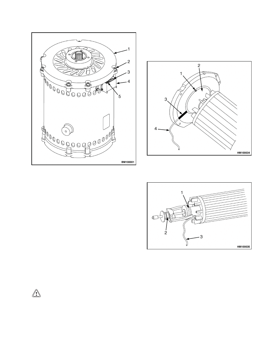
NOTE: AC TRACTION MOTOR USED ON NEWER
MODEL J2.00-3.20XM (J40-65Z) (A416) TRUCKS
SHOWN.
1.
END BELL
2.
SCREW
3.
ENCODER BEARING CONNECTOR
4.
CONNECTOR COVER
5.
TEMPERATURE SENSOR
Figure 4. AC Motor Assembly (Traction Motor
Shown)
NOTE: The encoder bearing must be oriented as
noted during removal.
2.
Using a bearing driver and arbor press, install
the encoder bearing as noted during removal.
3.
Place encoder wire through air guide and move
air guide back over encoder bearing. See Fig-
ure 7.
4.
Place end bell on rotor assembly.
CAUTION
To prevent damage to the encoder bearing, en-
sure encoder wire is inserted in end bell slot
when air guide is attached to the end bell.
5.
Insert encoder wire in the end bell slot and attach
air guide to end bell.
6.
Install eyebolt into end bell and rotor assembly
and connect a chain to the lifting eye.
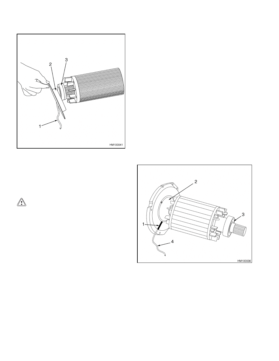
1.
SCREW
2.
AIR GUIDE
3.
END BELL SLOT
4.
ENCODER WIRE
Figure 5. Rotor Disassembly
1.
ENCODER BEARING
2.
BEARING PULLER
3.
ENCODER WIRE
Figure 6. Bearing Removal
3
AC Motor Repair
620 SRM 1053
1.
ENCODER WIRE
2.
AIR GUIDE
3.
ENCODER BEARING
Figure 7. Alignment of Air Guide and End Bell
7.
Lift the end bell and rotor assembly to a vertical
position.
CAUTION
To prevent damage to the encoder wire, line up
end bell and rotor assembly slot with visible
mark to guide encoder wire into end bell and
rotor assembly case.
8.
Using the alignment marks made during disas-
sembly, line up the end bell and rotor assembly
with the motor case.
9.
Lower the end bell and rotor assembly back into
the case and place the encoder bearing and tem-
perature sensor wires into position on the rubber
gasket.
10. Replace rubber gasket that covers the field wires.
11. Attach end bell and rotor assembly to AC motor
case.
12. Install temperature sensor wire and encoder
wire onto holding bracket.
13. Remove chain and lifting eye.
14. Install motor into the lift truck. See the Frame
SRM for your lift truck model for installation in-
formation.
DRIVE END BEARING, REPLACE
NOTE: Drive end bearing is to be replaced if worn or
damaged.
1.
Follow Step 1 through Step 10 of Disassemble
procedure.
2.
Using a bearing puller, remove drive end bearing
from shaft. See Figure 8.
3.
Using a bearing driver and arbor press, install
drive end bearing.
4.
Follow Step 3 through Step 13 of the Assemble
procedure.
1.
END BELL SLOT
2.
AIR GUIDE
3.
DRIVE END BEARING
4.
ENCODER WIRE
Figure 8. Alignment of End Shaft Bearing
4

620 SRM 1053
Troubleshooting
Troubleshooting
PROBLEM
POSSIBLE CAUSE
PROCEDURE OR ACTION
Truck moves slow or in a
jerky motion.
Encoder broken.
Replace encoder bearing.
Encoder wire broken.
Check and repair encoder wire or re-
place encoder bearing.
Temperature
sensor
wire
fails.
Measure resistance with ohmmeter.
Resistance should be 530 ohms at 25
C (77 F). Repair temperature sensor
wire. The temperature sensor wire
can be repaired, but the temperature
sensor cannot be repaired.
Stator wires fail.
Loss of insulation in wire.
Check resistance between winding
and case.
Resistance should be at
50,000 ohms or above.
5

NOTES
____________________________________________________________
____________________________________________________________
____________________________________________________________
____________________________________________________________
____________________________________________________________
____________________________________________________________
____________________________________________________________
____________________________________________________________
____________________________________________________________
____________________________________________________________
____________________________________________________________
____________________________________________________________
____________________________________________________________
____________________________________________________________
____________________________________________________________
____________________________________________________________
____________________________________________________________
____________________________________________________________
____________________________________________________________
____________________________________________________________
6


TECHNICAL PUBLICATIONS
620 SRM 1053
7/05 (4/05)(1/04)(11/03)(3/03) Printed in United Kingdom
Document Outline
Wyszukiwarka
Podobne podstrony:
1534733 1600SRM1054 (07 2005) UK EN
1556364 0620SRM1098 (07 2005) UK EN
1534735 2200SRM1056 (07 2005) UK EN
1566043 0620SRM1115 (08 2005) UK EN
1459370 1600SRM0720 (07 2005) UK EN
1596602 0100SRM1200 (07 2005) UK EN
1554634 2200SRM1078 (07 2005) UK EN
1468474 2200SRM0756 (07 2005) UK EN
1596605 8000SRM1203 (07 2005) UK EN
1580519 2200SRM1131 (07 2005) UK EN
1566043 0620SRM1115 (08 2005) UK EN
1459370 1600SRM0720 (07 2005) UK EN
więcej podobnych podstron