AC TRACTION MOTOR
REPAIR
J1.6-2.0XMT (J30-40ZT) [J160]
PART NO. 1566043
620 SRM 1115

SAFETY PRECAUTIONS
MAINTENANCE AND REPAIR
• When lifting parts or assemblies, make sure all slings, chains, or cables are correctly
fastened, and that the load being lifted is balanced. Make sure the crane, cables, and
chains have the capacity to support the weight of the load.
• Do not lift heavy parts by hand, use a lifting mechanism.
• Wear safety glasses.
• DISCONNECT THE BATTERY CONNECTOR before doing any maintenance or repair
on electric lift trucks. Disconnect the battery ground cable on internal combustion lift
trucks.
• Always use correct blocks to prevent the unit from rolling or falling. See HOW TO PUT
THE LIFT TRUCK ON BLOCKS in the Operating Manual or the Periodic Mainte-
nance section.
• Keep the unit clean and the working area clean and orderly.
• Use the correct tools for the job.
• Keep the tools clean and in good condition.
• Always use HYSTER APPROVED parts when making repairs. Replacement parts
must meet or exceed the specifications of the original equipment manufacturer.
• Make sure all nuts, bolts, snap rings, and other fastening devices are removed before
using force to remove parts.
• Always fasten a DO NOT OPERATE tag to the controls of the unit when making repairs,
or if the unit needs repairs.
• Be sure to follow the WARNING and CAUTION notes in the instructions.
• Gasoline, Liquid Petroleum Gas (LPG), Compressed Natural Gas (CNG), and Diesel fuel
are flammable. Be sure to follow the necessary safety precautions when handling these
fuels and when working on these fuel systems.
• Batteries generate flammable gas when they are being charged. Keep fire and sparks
away from the area. Make sure the area is well ventilated.
NOTE: The following symbols and words indicate safety information in this
manual:
WARNING
Indicates a condition that can cause immediate death or injury!
CAUTION
Indicates a condition that can cause property damage!

AC Traction Motor Repair
Table of Contents
TABLE OF CONTENTS
Introduction........................................................................................................................................................
General ...........................................................................................................................................................
Discharging the Capacitors...........................................................................................................................
Description .........................................................................................................................................................
Traction Motor ...............................................................................................................................................
AC Motor Repair ................................................................................................................................................
Remove ...........................................................................................................................................................
Disassemble ...................................................................................................................................................
Inspect ............................................................................................................................................................
Assemble ........................................................................................................................................................
Install .............................................................................................................................................................
Troubleshooting..................................................................................................................................................
This section is for the following models:
J1.6-2.0XMT (J30-40ZT) [J160]
©2005 HYSTER COMPANY
i

"THE
QUALITY
KEEPERS"
HYSTER
APPROVED
PARTS
620 SRM 1115
Introduction
Introduction
GENERAL
This section contains repair and maintenance proce-
dures for the AC traction motor. Additional infor-
mation concerning the traction motor may be more
closely related to other systems and included in those
sections. Sections that contain information regard-
ing the traction motors include:
AC Motor Controllers/Display Panel, De-
scription, Checks, Adjustments, and Trou-
bleshooting 2200 SRM 1087
Electrical System 2200 SRM 1078
Periodic Maintenance 8000 SRM 1079
WARNING
Do not make repairs or adjustments unless you
are properly trained and have authorization to
do so. Repairs and adjustments that are not
correct can create dangerous operating condi-
tions. Do not operate a lift truck that needs re-
pairs. Report the need for repairs to your su-
pervisor immediately. If repair is necessary, at-
tach a DO NOT OPERATE tag to the steering
wheel and remove the key.
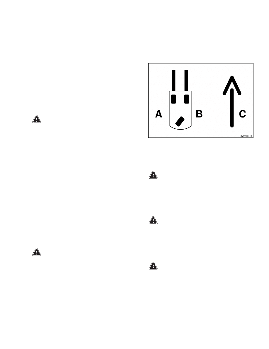
Throughout this section, forward will refer to travel
in the direction of the forks and left and right will
be determined by sitting in the seat facing forward.
See Figure 1. Troubleshooting information about the
traction motors is available through on-board diag-
nostics and may be displayed on the dash display. Re-
fer to the section AC Motor Controllers/Display
Panel, Description, Checks, Adjustments, and
Troubleshooting 2200 SRM 1087 for further expla-
nation of dash display codes concerning the traction
motors.
DISCHARGING THE CAPACITORS
WARNING
Do not make repairs or adjustments unless you
are properly trained and have authorization to
do so. Repairs and adjustments that are not
correct can create dangerous operating condi-
tions. Do not operate a lift truck that needs
repairs. Report the need for repairs to your
supervisor immediately. If repair is necessary,
attach a DO NOT OPERATE tag to the steering
wheel and remove the key.
A. LEFT SIDE
B. RIGHT SIDE
C. FORWARD TRAVEL
Figure 1. Truck Orientation
WARNING
Disconnect the battery before opening the elec-
trical compartment cover or inspecting or re-
pairing the electrical system. If a tool causes
a short circuit, the high current flow from the
battery can cause personal injury or property
damage.
WARNING
Some checks and adjustments are performed
with the battery connected. Do not connect the
battery until the procedure tells you to do so.
Never have any metal on your fingers, arms,
or neck. Metal items can accidentally make an
electrical connection and cause injury.
WARNING
Block the lift truck drive tires to prevent unex-
pected movement before performing any tests
or adjustments.
1
Introduction
620 SRM 1115
WARNING
The capacitor in the transistor controller can
hold an electrical charge after the battery is
disconnected. To prevent an electrical shock
and personal injury, discharge the capacitor
before inspecting or repairing any component
in the electrical compartment.
Wear safety
glasses.
Make certain that the battery has
been disconnected.
CAUTION
To avoid controller damage, always discon-
nect the battery and discharge the capacitor.
NEVER put power to the controller while any
power wires are disconnected. NEVER short
any controller terminal or motor terminal to
the battery. Make sure to use proper proce-
dure when servicing the controller.
1.
Block load wheels to prevent lift truck from mov-
ing.
2.
Turn key switch to OFF position and disconnect
the battery.
3.
Open the electrical compartment:
a. Remove two screws securing the electrical
compartment door.
b. Pull the compartment door open on its
hinges.
WARNING
DO NOT short across the motor controller ter-
minals with a screwdriver or jumper wire.
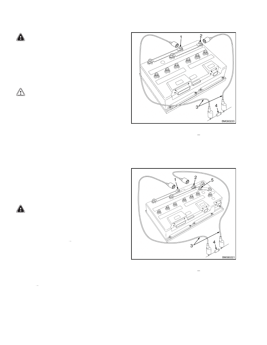
4.
Discharge the capacitor in the controller by con-
necting a 200-ohm, 2-watt resistor across the
controller’s BT+ and B
terminals for 10 seconds
using insulated jumper wires. See Figure 2.
NOTE: Some lift trucks are equipped with a premium
controller, which controls the hydraulic motor as well
as the traction motors.
5.
On the premium controller, also connect the 200-
ohm, 2-watt resistor across the controller’s P+
and B
terminals for 10 seconds using insulated
jumper wires. See Figure 3.
6.
Remove the 200-ohm, 2-watt resistor before re-
connecting the battery.
1.
POSITIVE CONNECTION (BT+)
2.
NEGATIVE CONNECTION (B )
3.
INSULATED JUMPER WIRES
4.
200-OHM, 2-WATT RESISTOR
Figure 2. Discharging the Capacitors
(Standard)
1.
POSITIVE CONNECTION (BT+)
2.
NEGATIVE CONNECTION (B )
3.
INSULATED JUMPER WIRES
4.
200-OHM, 2-WATT RESISTOR
5.
POSITIVE CONNECTION (P+)
Figure 3. Discharging the Capacitors
(Premium)
2
620 SRM 1115
Description
Description
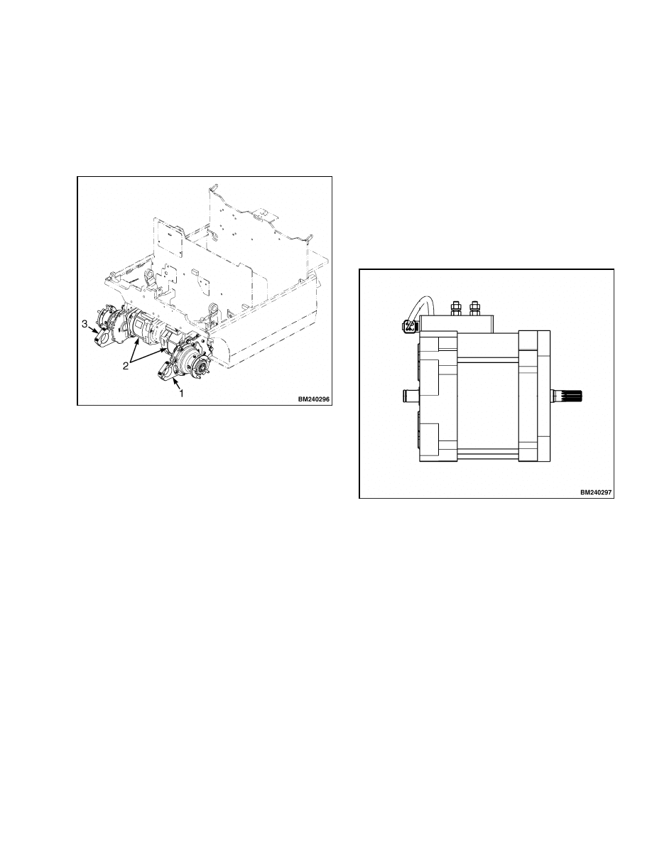
TRACTION MOTOR
Traction motors are mounted to the inside of each
transmission under the front end of the frame. See
Figure 4.
1.
LEFT TRANSMISSION
2.
TRACTION MOTORS
3.
RIGHT TRANSMISSION
Figure 4. Transmission Mounting
The traction motors are three-phase AC induction
motors. DC battery current is converted into AC cur-
rent in the controller and then supplied to the trac-
tion motors. The controller controls motor speed and
direction. Each traction motor contains a speed en-
coder device in the end head (brake) that provides
continuous motor speed and direction information to
the controller. A temperature sensor built into the
end head continually monitors motor temperature.
Brass terminals receive the power cables from the
controller and a small connector links the end head
(brake) wiring harness to the main wiring harness.
The rotor shaft extends out each side of the traction
motor. The splined end of the shaft engages the input
gear in the transaxle. A short, round section of the
shaft protrudes from the other side of the motor. This
end supports the parking brake hub using a woodruff
key and a snap ring. See Figure 5.
Figure 5. Traction Motor
3

AC Motor Repair
620 SRM 1115
AC Motor Repair
REMOVE
1.
Turn the key switch to the OFF position and dis-
connect the battery. Block the steer tires to pre-
vent unexpected movement.
2.
Remove the mast assembly.
See the section
Mast, Description 4000 SRM 521.
3.
Position the front of the lift truck on solid hard-
wood blocks so the drive tires are suspended
off the floor. See the section Periodic Main-
tenance 8000 SRM 1079 for instructions on
putting the lift truck on blocks.
4.
Remove the transaxle assembly from the lift
truck.
See the section Transaxle 1300 SRM
1074.
5.
Remove the four capscrews and washers mount-
ing the traction motor to the transaxle.
6.
Remove the traction motor from the transaxle.
DISASSEMBLE
1.
Remove the four capscrews, lockwashers, and
washers securing the brake assembly to the
drive motor. Remove the brake assembly from
the splined hub.
2.
Remove the snap ring securing the splined hub
from the traction motor shaft.
Remove the
splined hub and key.
3.
Remove the socket-head capscrews and lock-
washers securing motor assembly together. See
Figure 6.
NOTE: Carefully tap the underside of the end head
with a soft hammer to loosen the end head from the
stator.
4.
Remove the end head (brake) from the stator and
slide the end head off the rotor shaft.
5.
Remove the rotor from the stator. Place the sta-
tor brake end down on the workbench.
NOTE: Carefully tap the underside of the end head
with a soft hammer to loosen the end head from the
stator.
6.
Remove the end head (transaxle) from the stator.
7.
If necessary, remove the nuts and washers secur-
ing the connection plate to the stator, and remove
the connection plate.
INSPECT
Inspect the rotor and the inside of the stator for
marks or grooves indicating contact between the
rotor and the stator. Replace if damaged. Check
that the bearing rolls smoothly and is not loose from
excessive wear. Replace end head (brake) assembly
if bearing is worn/damaged. If there is damage from
contact between the rotor and the stator or to other
components, replace damaged components or the
complete traction motor assembly if necessary.
ASSEMBLE
1.
Install end head (transaxle) into stator as re-
moved.
2.
Install rotor into stator with drive splines pro-
truding through the end head (transaxle).
3.
Install connector to end head (brake) wiring har-
ness if replacing, and secure connector to end
head (brake) as removed.
4.
Install connection plate to stator, if removed.
5.
Install end head (brake) onto rotor shaft and into
stator as removed.
6.
Install end head wiring harness into grommet
and install grommet into connector plate.
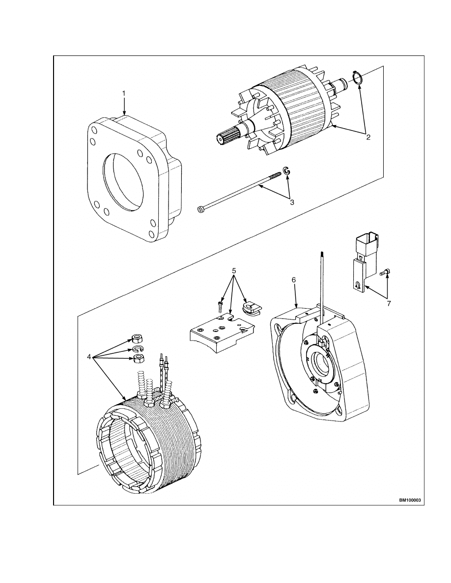
Legend for Figure 6
1.
END HEAD (TRANSAXLE)
2.
ROTOR
3.
SOCKET-HEAD CAPSCREW AND
LOCKWASHER
4.
STATOR, TERMINALS, AND HARDWARE
5.
CONNECTION PLATE, SCREW, AND GROMMET
6.
END HEAD (BRAKE)
7.
CONNECTOR AND SCREW
4
620 SRM 1115
AC Motor Repair
Figure 6. AC Traction Motor
5

Troubleshooting
620 SRM 1115
NOTE: Only torque values for nonstandard applica-
tions are specifically stated. Refer to the section Met-
ric and Inch (SAE) Fasteners 8000 SRM 231 for
standard torque specifications.
7.
Install socket-head capscrews and lockwashers
through the end head (transaxle) and into the
end head (brake) securing motor assembly.
8.
Install the splined hub and key to the traction
motor shaft. Install the snap ring securing the
hub.
9.
Install the brake assembly onto the splined hub.
Install the four capscrews, lockwashers, and
washers securing the brake assembly to the
drive motor as removed.
INSTALL
1.
Position the traction motor onto the transaxle as
removed.
2.
Install the four capscrews and washers mount-
ing the traction motor to the transaxle. Apply
Loctite™ 271 and torque to 48 N•m (35 lbf ft).
3.
Install the transaxle assembly to the lift truck.
Secure using five capscrews. Apply Loctite™ 271
and torque to 220 N•m (162 lbf ft). See the sec-
tion Transaxle 1300 SRM 1074.
4.
Connect all wiring and cables as removed. Hold
the lower nut of the terminal stud to prevent
it from turning and tighten the upper nut to
10 N•m (89 lbf in).
WARNING
Bleed the service brakes when the transaxle
has been removed. Refer to the section Peri-
odic Maintenance 8000 SRM 1079.
NOTE: Check the transaxle oil level and fill as needed
each time any service is performed on the transaxle
assembly.
5.
Lower the lift truck from the blocks.
6.
Turn the key switch to the ON position and con-
nect the battery. Remove the blocks from the
wheels. Test for proper operation.
7.
Install the mast assembly. See the section Mast,
Description 4000 SRM 521. Check the mast
for proper operation and return the lift truck to
service.
Troubleshooting
PROBLEM
POSSIBLE CAUSE
PROCEDURE OR ACTION
Truck moves slow or acceler-
ates erratically.
End head (brake) wire harness dam-
aged.
Check and repair end head (brake)
wire harness or replace end head
(brake) assembly if necessary.
Main wiring harness damaged.
Test traction motor circuit through
main wiring harness from connection
at controller.
Encoder bearing damaged.
Replace end head (brake) - includes
encoder bearing and temperature
sensor.
Throttle position sensor broken or
out of adjustment.
Troubleshoot the accelerator assem-
bly.
Parking brake not releasing.
Troubleshoot the parking brakes.
6

620 SRM 1115
Troubleshooting
PROBLEM
POSSIBLE CAUSE
PROCEDURE OR ACTION
Temperature
sensor
mal-
function.
End head (brake) wire harness dam-
aged.
Check and repair end head (brake)
wire harness or replace end head
(brake) if necessary.
Main wiring harness damaged.
Test
temperature
sensor
circuit
through main wiring harness from
connection at controller.
Temperature sensor open or shorted.
Measure resistance with ohmmeter.
Resistance should between 514 and
700 ohms. Replace end head (brake)
if necessary.
Traction motor does not oper-
ate.
Battery lacks sufficient charge.
Charge/change battery.
Throttle position sensor or neutral
switch broken or out of adjustment.
Troubleshoot the accelerator assem-
bly.
Electrical system malfunction.
Troubleshoot the electrical system.
Operator presence switch malfunc-
tion.
Check wiring/connectors.
Replace
switch if necessary.
Stator coil shorted to case.
Check resistance between winding
and case.
Resistance should be at
50,000 ohms or above. Replace sta-
tor or traction motor assembly if
necessary.
Stator wires broken-open circuit.
Check
resistance
between
motor
terminals U, V, and W. Resistance
should read less than 1 ohm between
each terminal.
Replace stator or
traction motor assembly if necessary.
Parking brake not releasing/dam-
aged.
Troubleshoot the parking brakes.
Transaxle internal damage.
Check that the transaxle rotates
smoothly.
7

Troubleshooting
620 SRM 1115
PROBLEM
POSSIBLE CAUSE
PROCEDURE OR ACTION
Unusual noise from traction
motor.
Traction motor bearing damaged.
Replace end head(s) and check stator
and rotor for damage. Replace dam-
aged components or traction motor if
necessary.
Parking brake not releasing/dam-
aged.
Troubleshoot the parking brakes.
Transaxle internal damage.
Check that the transaxle rotates
smoothly.
8


TECHNICAL PUBLICATIONS
620 SRM 1115
8/05 (6/04) Printed in United Kingdom
Document Outline
Wyszukiwarka
Podobne podstrony:
1568204 0700SRM1159 (08 2005) UK EN
910091 1900SRM0097 (08 2005) UK EN
1565789 1800SRM1117 (08 2005) UK EN
1569718 4000SRM1160 (08 2005) UK EN
1529749 1800SRM1036 (08 2005) UK EN
1574068 1400SRM1171 (08 2005) UK EN
1565653 2100SRM1116 (08 2005) UK EN
1534732 0620SRM1053 (07 2005) UK EN
1596604 8000SRM1202 (08 2005) UK EN(1)
1556364 0620SRM1098 (07 2005) UK EN
1568204 0700SRM1159 (08 2005) UK EN
więcej podobnych podstron