DIAGRAMS
AC MOTOR CONTROL SYSTEM
E3.50-5.50XL, E4.50XLS
(E70-120Z, E100ZS) [D098]
PART NO. 1596605
8000 SRM 1203

SAFETY PRECAUTIONS
MAINTENANCE AND REPAIR
• When lifting parts or assemblies, make sure all slings, chains, or cables are correctly
fastened, and that the load being lifted is balanced. Make sure the crane, cables, and
chains have the capacity to support the weight of the load.
• Do not lift heavy parts by hand, use a lifting mechanism.
• Wear safety glasses.
• DISCONNECT THE BATTERY CONNECTOR before doing any maintenance or repair
on electric lift trucks. Disconnect the battery ground cable on internal combustion lift
trucks.
• Always use correct blocks to prevent the unit from rolling or falling. See HOW TO PUT
THE LIFT TRUCK ON BLOCKS in the Operating Manual or the Periodic Mainte-
nance section.
• Keep the unit clean and the working area clean and orderly.
• Use the correct tools for the job.
• Keep the tools clean and in good condition.
• Always use HYSTER APPROVED parts when making repairs. Replacement parts
must meet or exceed the specifications of the original equipment manufacturer.
• Make sure all nuts, bolts, snap rings, and other fastening devices are removed before
using force to remove parts.
• Always fasten a DO NOT OPERATE tag to the controls of the unit when making repairs,
or if the unit needs repairs.
• Be sure to follow the WARNING and CAUTION notes in the instructions.
• Gasoline, Liquid Petroleum Gas (LPG), Compressed Natural Gas (CNG), and Diesel fuel
are flammable. Be sure to follow the necessary safety precautions when handling these
fuels and when working on these fuel systems.
• Batteries generate flammable gas when they are being charged. Keep fire and sparks
away from the area. Make sure the area is well ventilated.
NOTE: The following symbols and words indicate safety information in this
manual:
WARNING
Indicates a condition that can cause immediate death or injury!
CAUTION
Indicates a condition that can cause property damage!

Diagrams
Table of Contents
TABLE OF CONTENTS
Diagrams, Schematics, or Arrangements .........................................................................................................
Figure 1. Wiring Schematic Diagram for E3.50-5.50XL, E4.50XLS (E70-120Z, E100ZS)
(D098).........................................................................................................................................................
Figure 2. Schematic Wiring Diagram 12 Volt Lights E3.50-5.50XL, E4.50XLS (E70-120Z,
E100ZS) (D098) .........................................................................................................................................
Figure 3. Hydraulic Schematic E3.50-5.50XL, E4.50XLS (E70-120Z, E100ZS) (D098) .......................
Figure 4. Lift Truck Power Cables E3.50-5.50XL, E4.50XLS (E70-120Z, E100ZS) (D098) ..................
Figure 5. Control Panel Wiring E3.50-5.50XL, E4.50XLS (E70-120Z, E100ZS) (D098) .......................
Figure 6. Wiring Schematic Diagram for AC Traction and Pump Motor Controllers, Gen V,
E3.50-5.50XL, E4.50XLS (E70-120Z, E100ZS) (D098)............................................................................
Figure 7. Lights Wiring Arrangement E3.50-5.50XL, E4.50XLS (E70-120Z, E100ZS) (D098) ............
This section is for the following models:
E3.50-5.50XL, E4.50XLS (E70-120Z, E100ZS) [D098]
©2005 HYSTER COMPANY
i

"THE
QUALITY
KEEPERS"
HYSTER
APPROVED
PARTS
8000 SRM 1203
Diagrams, Schematics, or Arrangements
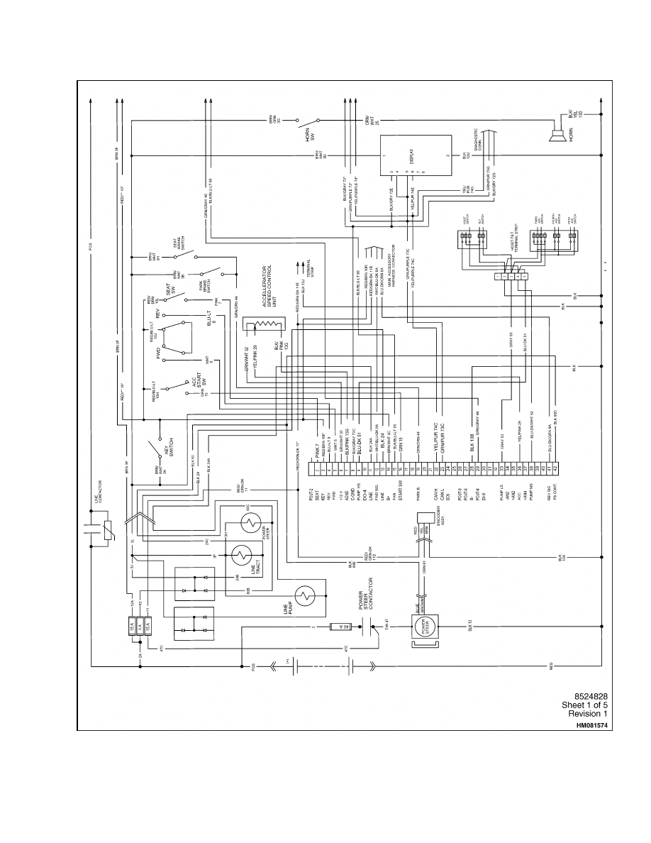
Figure 1. Wiring Schematic Diagram for E3.50-5.50XL, E4.50XLS (E70-
120Z, E100ZS) (D098) (Sheet 1 of 5)
1
Diagrams, Schematics, or Arrangements
8000 SRM 1203
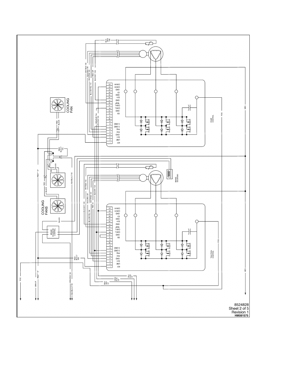
Figure 1. Wiring Schematic Diagram for E3.50-5.50XL, E4.50XLS (E70-
120Z, E100ZS) (D098) (Sheet 2 of 5)
2
8000 SRM 1203
Diagrams, Schematics, or Arrangements
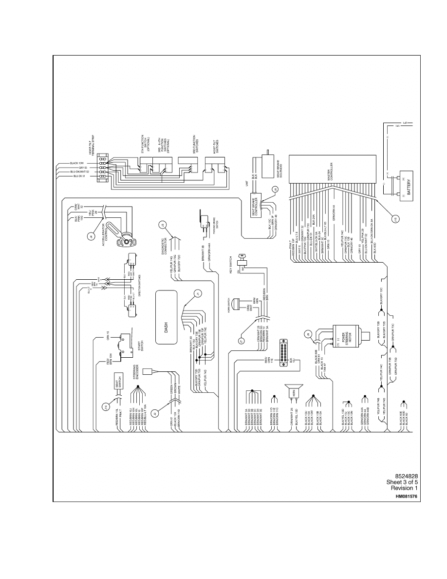
Figure 1. Wiring Schematic Diagram for E3.50-5.50XL, E4.50XLS (E70-
120Z, E100ZS) (D098) (Sheet 3 of 5)
3
Diagrams, Schematics, or Arrangements
8000 SRM 1203
Figure 1. Wiring Schematic Diagram for E3.50-5.50XL, E4.50XLS (E70-
120Z, E100ZS) (D098) (Sheet 4 of 5)
4
8000 SRM 1203
Diagrams, Schematics, or Arrangements
Figure 1. Wiring Schematic Diagram for E3.50-5.50XL, E4.50XLS (E70-
120Z, E100ZS) (D098) (Sheet 5 of 5)
5
Diagrams, Schematics, or Arrangements
8000 SRM 1203
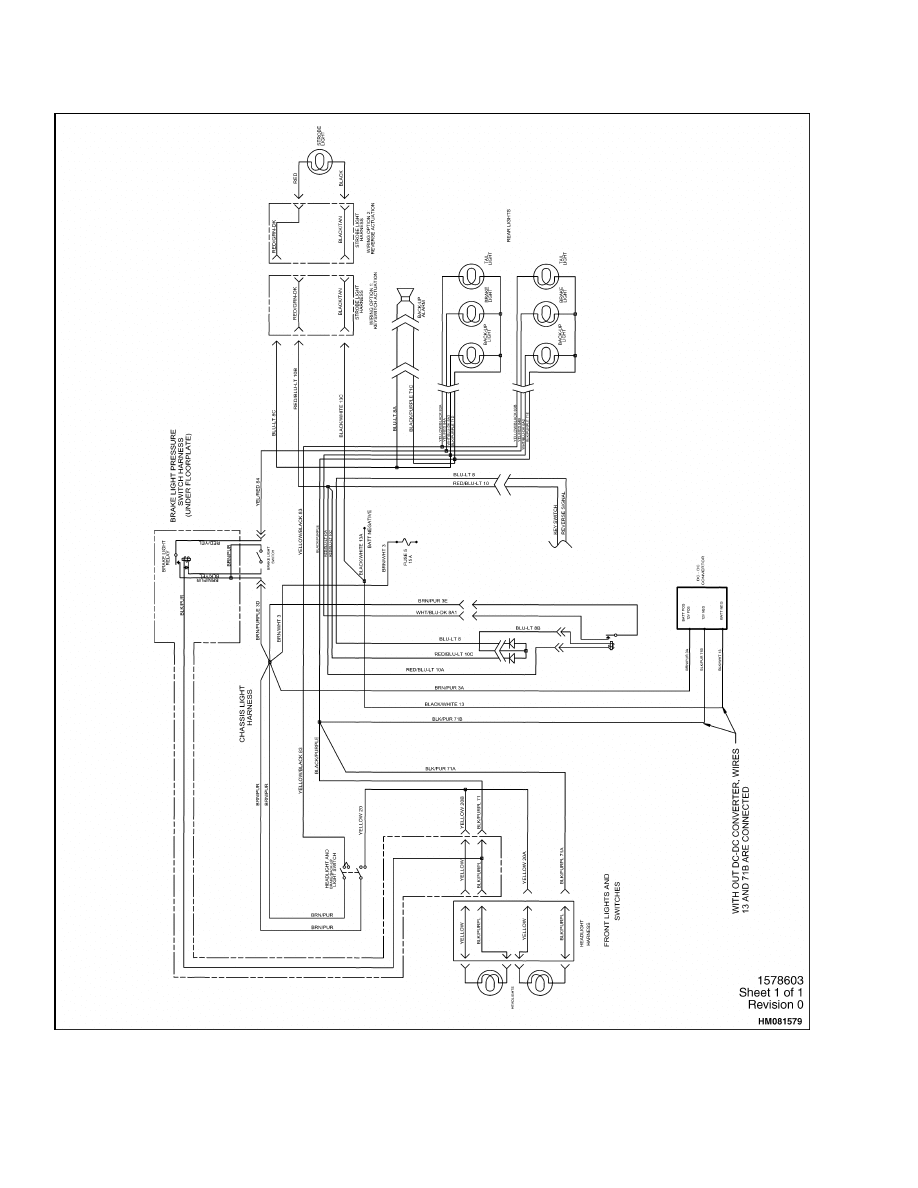
Figure 2. Schematic Wiring Diagram 12 Volt Lights E3.50-5.50XL, E4.50XLS (E70-120Z, E100ZS)
(D098)
6
8000 SRM 1203
Diagrams, Schematics, or Arrangements
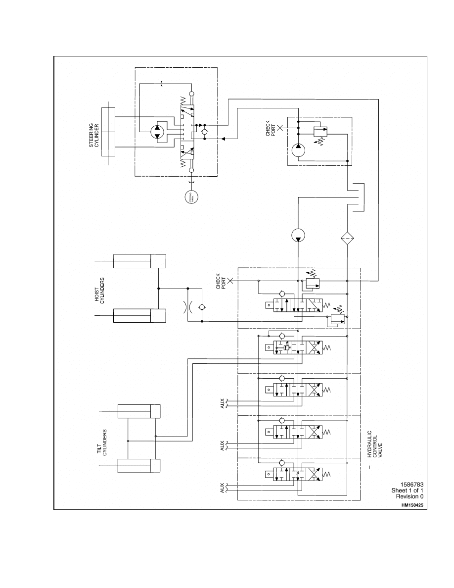
Figure 3. Hydraulic Schematic E3.50-5.50XL, E4.50XLS (E70-120Z, E100ZS) (D098)
7
Diagrams, Schematics, or Arrangements
8000 SRM 1203
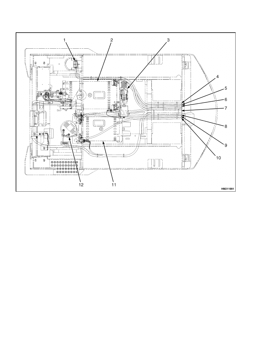
1.
BATTERY CONNECTOR
2.
TRACTION MOTOR
3.
SEAT BRAKE
4.
TRACTION MOTOR CABLE (UT)
5.
TRACTION MOTOR CABLE (VT)
6.
TRACTION MOTOR CABLE (WT)
7.
MAIN WIRING HARNESS
8.
HYDRAULIC PUMP MOTOR CABLE (UP)
9.
HYDRAULIC PUMP MOTOR CABLE (VP)
10. HYDRAULIC PUMP MOTOR CABLE (WP)
11. HYDRAULIC PUMP MOTOR
12. STEERING PUMP MOTOR
Figure 4. Lift Truck Power Cables E3.50-5.50XL, E4.50XLS (E70-120Z, E100ZS) (D098)
8
8000 SRM 1203
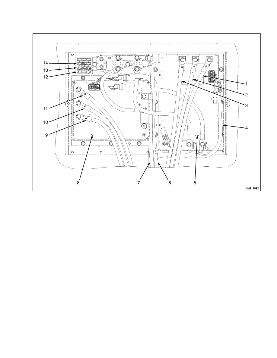
Diagrams, Schematics, or Arrangements
1.
TRACTION MOTOR CABLE (UT)
2.
TRACTION MOTOR CABLE (VT)
3.
TRACTION MOTOR CABLE (WT)
4.
MAIN WIRING HARNESS
5.
TRACTION MOTOR CONTROLLER
6.
BATTERY POSITIVE CABLE (B+)
7.
BATTERY NEGATIVE CABLE (B-)
8.
HYDRAULIC PUMP MOTOR CONTROLLER
9.
HYDRAULIC PUMP MOTOR CABLE (UP)
10. HYDRAULIC PUMP MOTOR CABLE (VP)
11. HYDRAULIC PUMP MOTOR CABLE (WP)
12. KEY SWITCH FUSE (5A)
13. LIGHTS FUSE (15A)
14. ELECTRIC SEAT BRAKE FUSE (15A)
15. TERMINAL STRIP FUSE (15A)
Figure 5. Control Panel Wiring E3.50-5.50XL, E4.50XLS (E70-120Z, E100ZS) (D098)
9

Diagrams, Schematics, or Arrangements
8000 SRM 1203
10
8000 SRM 1203
Diagrams, Schematics, or Arrangements
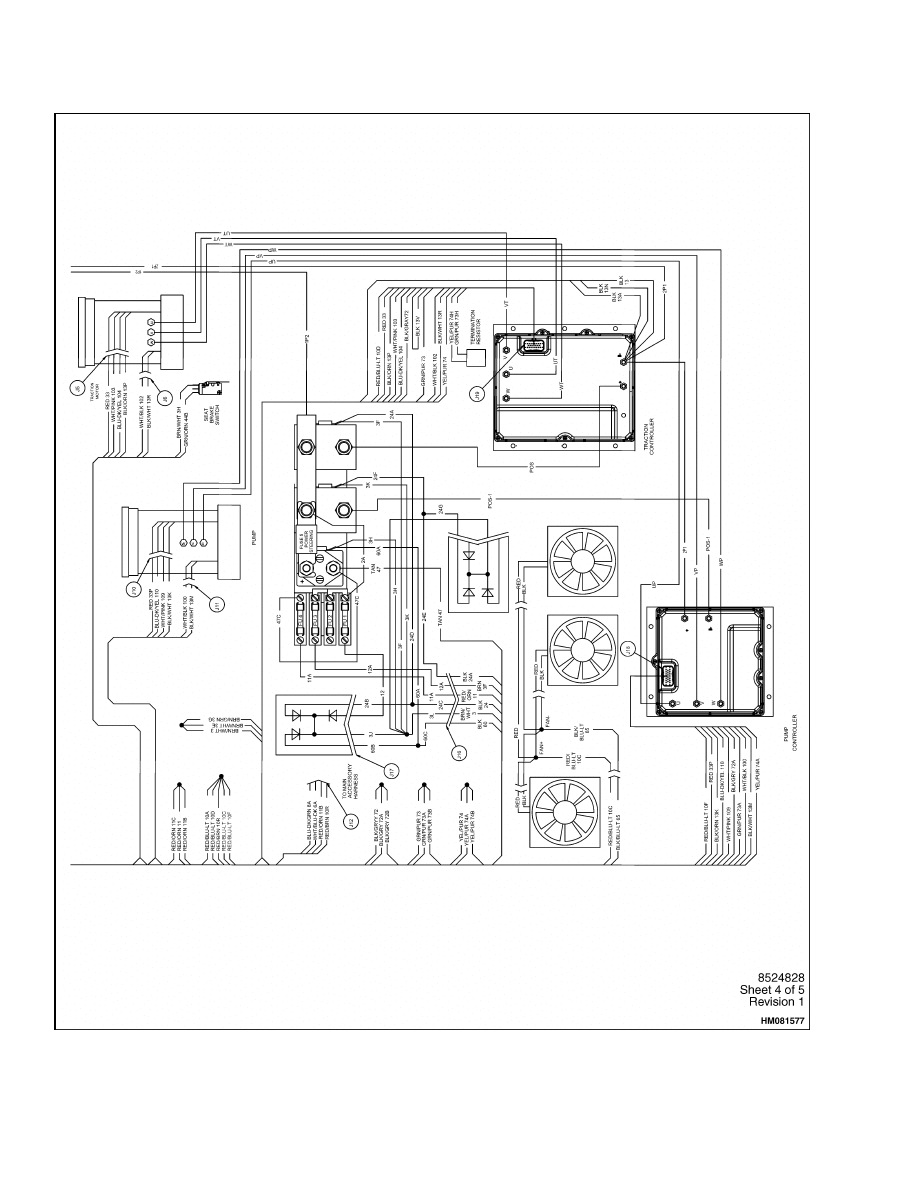
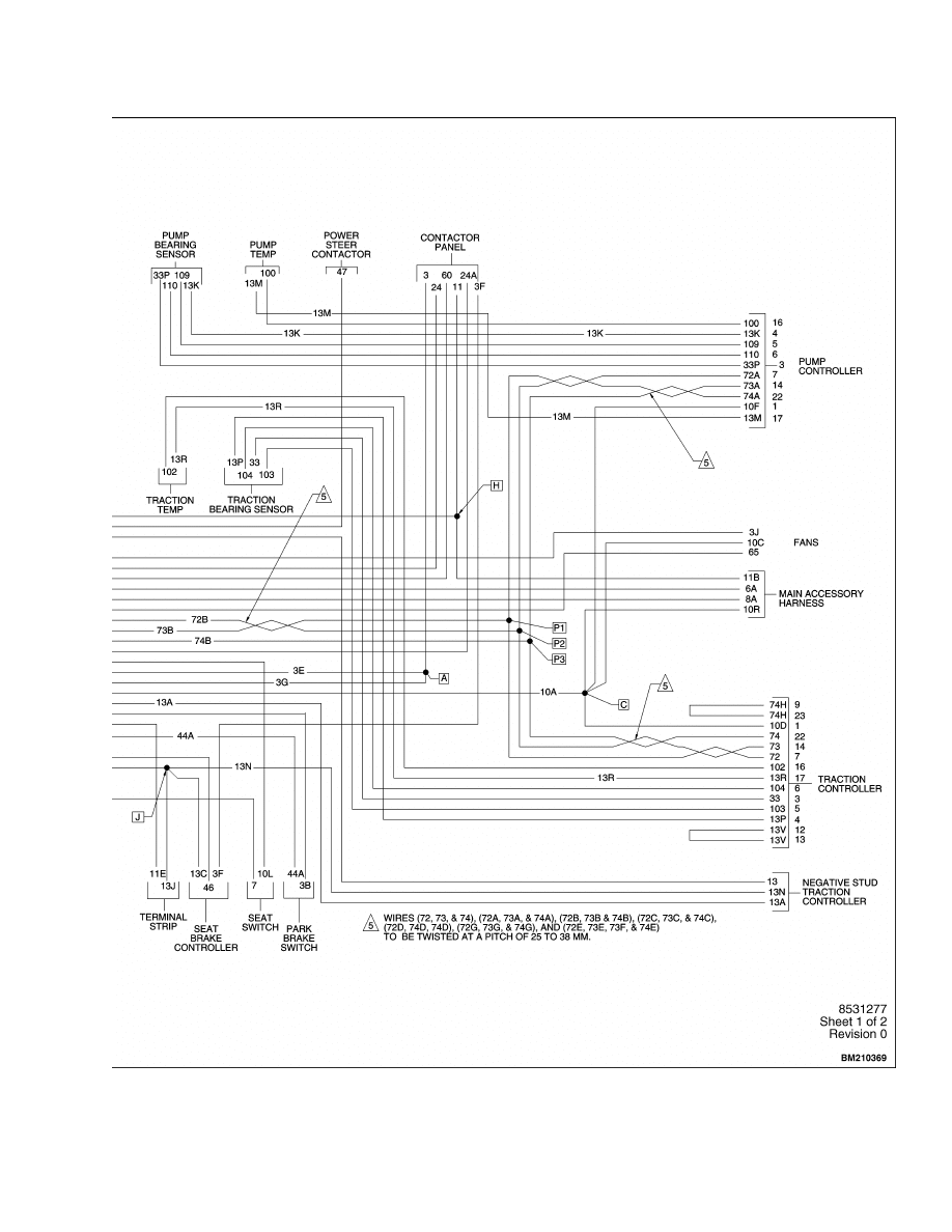
Figure 6. Wiring Schematic Diagram for AC Traction and Pump Motor Controllers, Gen
V, E3.50-5.50XL, E4.50XLS (E70-120Z, E100ZS) (D098) (Sheet 1 of 2)
11
Diagrams, Schematics, or Arrangements
8000 SRM 1203
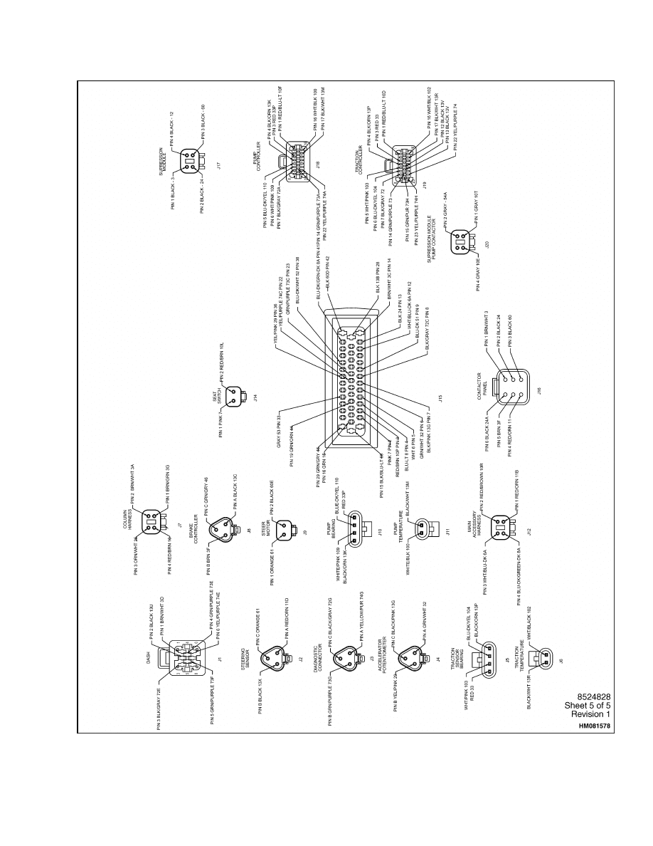
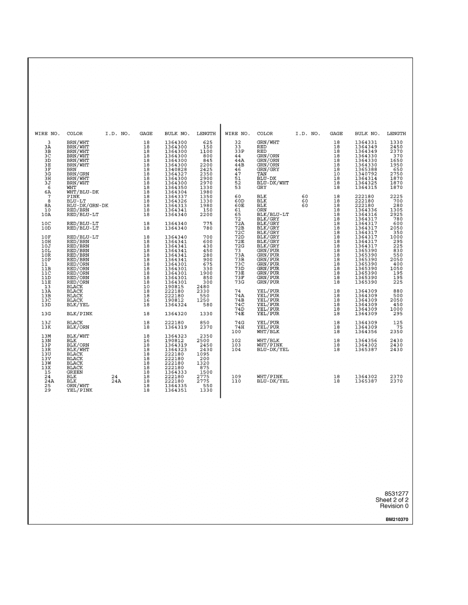
Figure 6. Wiring Schematic Diagram for AC Traction and Pump Motor Controllers, Gen
V, E3.50-5.50XL, E4.50XLS (E70-120Z, E100ZS) (D098) (Sheet 2 of 2)
12
8000 SRM 1203
Diagrams, Schematics, or Arrangements
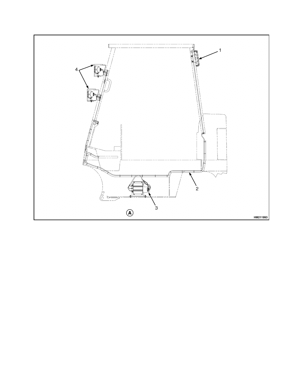
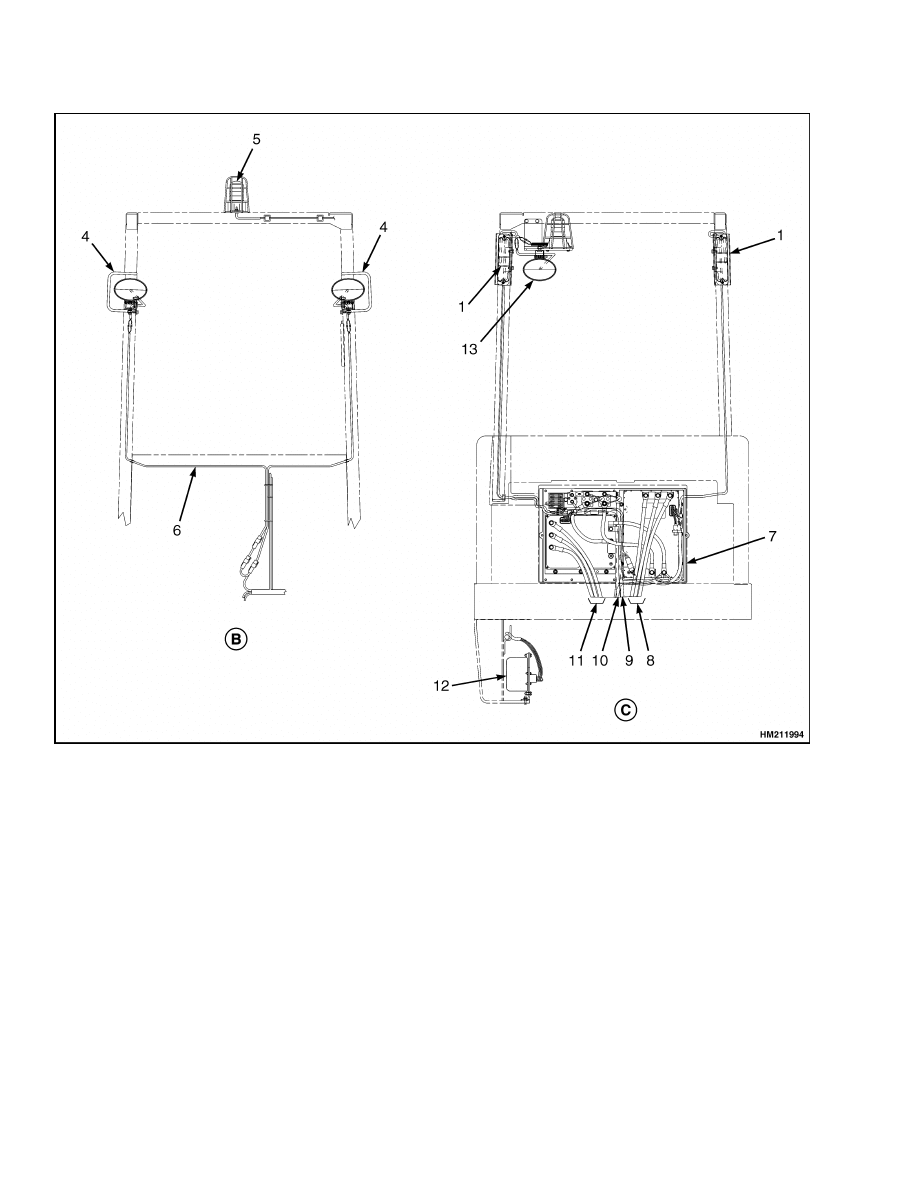
Figure 7. Lights Wiring Arrangement E3.50-5.50XL, E4.50XLS (E70-120Z,
E100ZS) (D098) (Sheet 1 of 2)
13
Diagrams, Schematics, or Arrangements
8000 SRM 1203
A. SIDE VIEW
B. FRONT VIEW
C. REAR VIEW
1.
REVERSE/BRAKE LIGHT
2.
MAIN WIRING HARNESS
3.
DC CONVERTER
4.
FRONT HEADLIGHT ASSEMBLY
5.
STROBE LIGHT
6.
HEADLIGHT WIRING HARNESS
7.
CONTROL PANEL
8.
TRACTION MOTOR POWER CABLES
9.
BATTERY POSITIVE CABLE (B+)
10. BATTERY NEGATIVE CABLE (B-)
11. HYDRAULIC PUMP MOTOR POWER CABLES
12. 24 VOLT RELAY
13. REAR HEADLIGHT
Figure 7. Lights Wiring Arrangement E3.50-5.50XL, E4.50XLS (E70-120Z,
E100ZS) (D098) (Sheet 2 of 2)
14


TECHNICAL PUBLICATIONS
8000 SRM 1203
7/05 (3/05) Printed in United Kingdom
Document Outline
Wyszukiwarka
Podobne podstrony:
1596602 0100SRM1200 (07 2005) UK EN
1596604 8000SRM1202 (08 2005) UK EN(1)
1510478 8000SRM0988 (06 2005) UK EN
1459370 1600SRM0720 (07 2005) UK EN
1526432 8000SRM1041 (07 2002) UK EN
1566279 8000SRM1155 (02 2005) UK EN
1554634 2200SRM1078 (07 2005) UK EN
1468474 2200SRM0756 (07 2005) UK EN
897875 8000SRM0616 (03 2005) UK EN
1580526 8000SRM1151 (05 2005) UK EN
1534732 0620SRM1053 (07 2005) UK EN
1580519 2200SRM1131 (07 2005) UK EN
1495208 8000SRM0949 (03 2005) UK EN
1458783 8000SRM0592 (03 2005) UK EN
1534733 1600SRM1054 (07 2005) UK EN
więcej podobnych podstron