
Cent. Eur. J. Eng. • 1(3) • 2011 • 217-233
DOI: 10.2478/s13531-011-0024-7
Central European Journal of Engineering
Physical Concept of Shear Fracture Mesomechanism
and its Applications
Vision article
Edward S. Dzidowski
∗
Wroclaw University of Technology, Faculty of Mechanical Engineering, 25 Smoluchowskiego Str., PL 50-372, Wroclaw, Poland
Received 08 February 2011; accepted 26 May 2011
Abstract:
The key objective of the present paper is an attempt to create an interface between the existing inconsistent views
on the microscopic and macroscopic aspects of the mechanism of plastic deformation and shear fracture. This
will be enabled by a focus on the course and effects of the evolution of dislocation structure, and will consist in
considering an indirect, i.e. a mesoscopic scale of the discussed phenomena. Thanks to this, a synergy between
the mechanisms of deformation and fracture of materials will be proven, which will provide an opportunity for a
smooth transfer from the microscopic, through mesoscopic, to macroscopic scale of the analysed phenomena.
This in turn will offer an opportunity to define and use the new criteria for controlling the mechanism of shear
fracture. These criteria will be applicable to the complete range of temperatures and strain rates which are
typical of metal working processes. Some examples of how these criteria may be applied in order to optimise
the parameters of metal working will also be provided. These examples have made it possible to prove that the
physical approach to shear fracture mesomechanism offers much broader cognitive and utilitarian opportunities
than the existing purely mathematical methods. This is due to the fact that the physical approach allows for a
deeper understanding of shear fracture meso- and macromechanism, and generates new criteria controlling this
mechanism.
Keywords:
Shear fracture • Mesomechanism • Macromechanism • Synergy • Control • Criteria • Applications
© Versita Sp. z o.o.
1.
Introduction
The fracture of materials is a primary restriction for the ef-
fective use of metal working processes. The above problem
is intensified by the lack of a coherent theory of deforma-
tion and fracture resulting from large plastic deformation.
This state of affairs impedes the analysis of cause and
effect relationships and consequently affects the predic-
tion, prevention and/or control of the course of fracture
∗
E-mail: edward.dzidowski@pwr.wroc.pl
of materials during metal working processes. The most
acute problem is lack of capacity to control the course of
fracture which in many cases involves no danger but is
essential to metal working processes including shearing
off, die shearing, or machining.
Therefore, the key objective of the present paper is an
attempt to create an interface between the existing incon-
sistent views on the microscopic and macroscopic aspects
of the mechanism of plastic deformation and shear fracture.
This will be enabled by a focus on the course and effects
of the evolution of dislocation structure, and will consist
in considering an indirect, i.e. a mesoscopic scale of the
discussed phenomena. Thanks to this, a synergy between
217
Physical Concept of Shear Fracture Mesomechanism and its Applications
the mechanisms of deformation and fracture of materials
will be proven, which will provide an opportunity for a
smooth transfer from the microscopic, through mesoscopic,
to macroscopic scale of the analysed phenomena. This in
turn will offer an opportunity to define and use the new
criteria for controlling the mechanism of shear fracture.
These criteria will be applicable to the complete range of
temperatures and strain rates which are typical of metal
working processes. Some examples of how these criteria
may be applied in order to optimise the parameters of cold
and hot metal working will also be provided.
Moreover, the usefulness of mesoscopic fracture concept
will be presented with a view to revise the existing opin-
ions on the forming limit diagram for sheet metal forming
processes, as well as the views on the mechanisms of the
formation of various chip types in the course of machin-
ing. Another example of the application of those criteria
will be to prove the usefulness of mesomechanics for the
interpretation of the reasons for the degradation of the
properties of materials which are to be used in increased
temperatures. The issue discussed here is the degradation
of useful properties resulting from cold metal working. To
provide an example, the above refers to the pipe bending
process applied in the construction of pipelines in heat
and power generating plants, and other similar facilities.
The perspective of further development and wider usage
of the mesoscopic concept of failure and fracture of mate-
rials accompanying large plastic deformation will also be
indicated.
2.
Hitherto existing views on the
mechanisms of fracture of materials
2.1.
Macroscopic views on the mechanism of
shear fracture
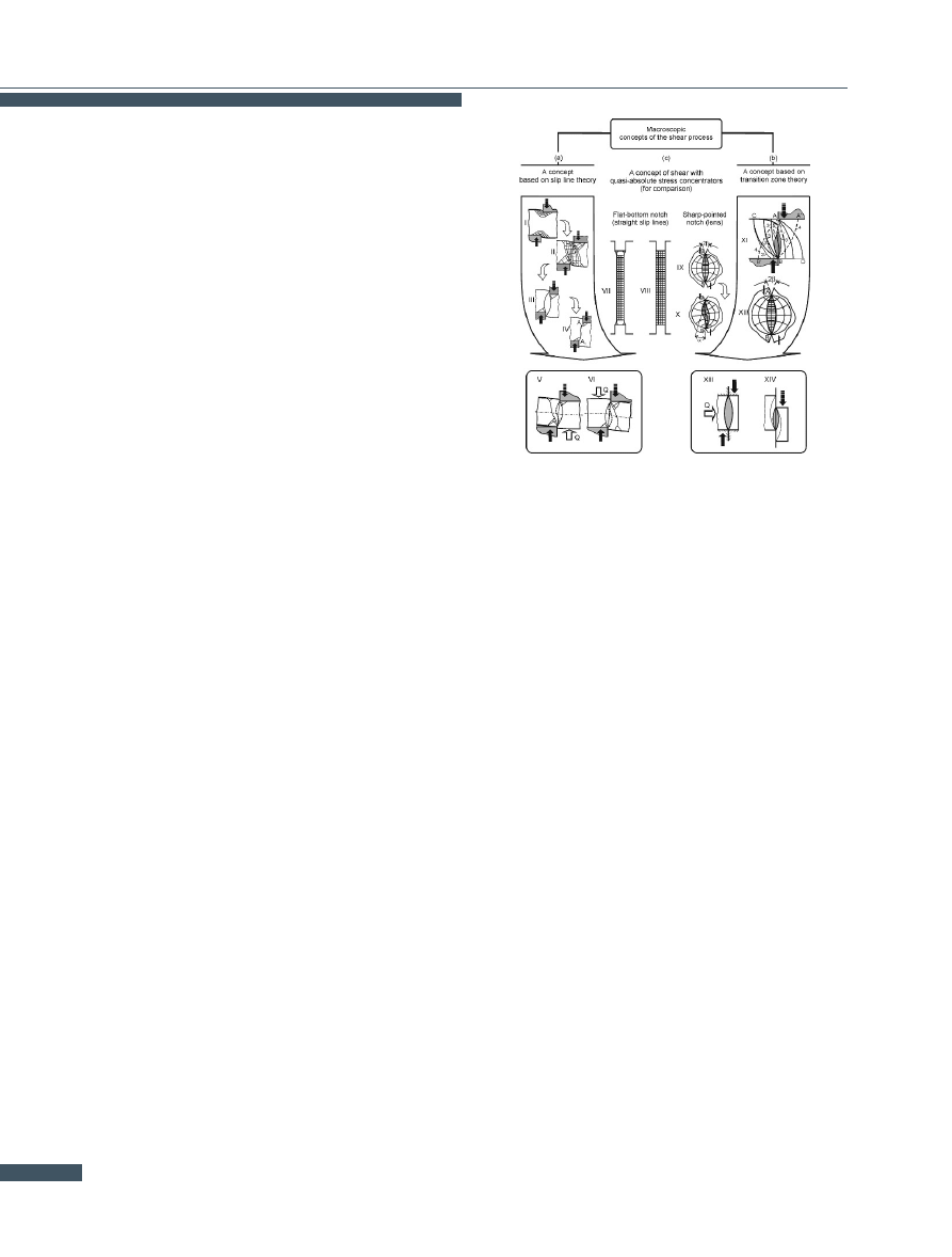
The earlier macroscopic methods of the analysis of the
development of strains and fracture in processes based
on shear were based mainly on the slip line field theory
and the theory of transition zones. Both theories have
serious limitations. According to the slip line field the-
ory (Fig.
a), the plastic sinking of the cutting tool in the
sheared material first causes gradual widening and then
narrowing of the plastic strain area [
]. Characteristically,
this area finally assumes the shape and dimensions of a
line (a plane) with zero thickness (Fig.
a, IV). The line
defines the location of slip velocity discontinuity and it
is identified with the presumed trajectory of fracture. It
is thought that the only way in which the shape of the
fracture trajectory can be changed is by eliminating the
rotation (bending) of the sheared material, which is usu-
Figure 1.
Macroscopic concepts of shear process: a) shear stages
according to slip line theory (I-IV) and effect of clamp Q on
shape of slip velocity discontinuity line as likely fracture
trajectory (V-VI); b) shear stages according to transition
zone theory (XI-XIV); c) distribution of slip lines for shear
with flat (VII-VIII) and sharp-pointed (IX-X) stress concen-
trator. Based on [
ally done by pressing the sheared material against the
cutting tool (Fig.
a, V-VI). With this the possibilities of
the method are exhausted. The fact that shear strain de-
termined by this method approaches infinity poses an ad-
ditional problem. The problem has been partially solved
by the development of the theory of transitional zones.
The introduction of the theory of transitional zones
(Fig.
b) made the values and distribution of strain in
the final stage of shearing real [
]. This means that in-
stead of a line (a surface) with zero thickness (Fig
a, IV),
an area having the shape of a biconvex lens is considered
(Fig.
b, XI-XII). The beginning of the formation of this
area is identified with conditions corresponding to the ac-
tion of an absolute stress concentrator (Fig.
c, VII-X). But
it is not known when and why such a significant change in
the stress concentration conditions occurs. Moreover, it is
assumed that once the lens is formed, it does not change
its shape but only diminishes as the displacement of the
cutting tool increases (Fig.
c, XIII-XIV).
To sum up, the above macroscopic theories do not explain
clearly enough the mechanism and causes of the fracture
of a material during its shearing. This makes the control
and optimisation of shear-based processes (machining, die
shearing, etc.) difficult.
218
E. S. Dzidowski
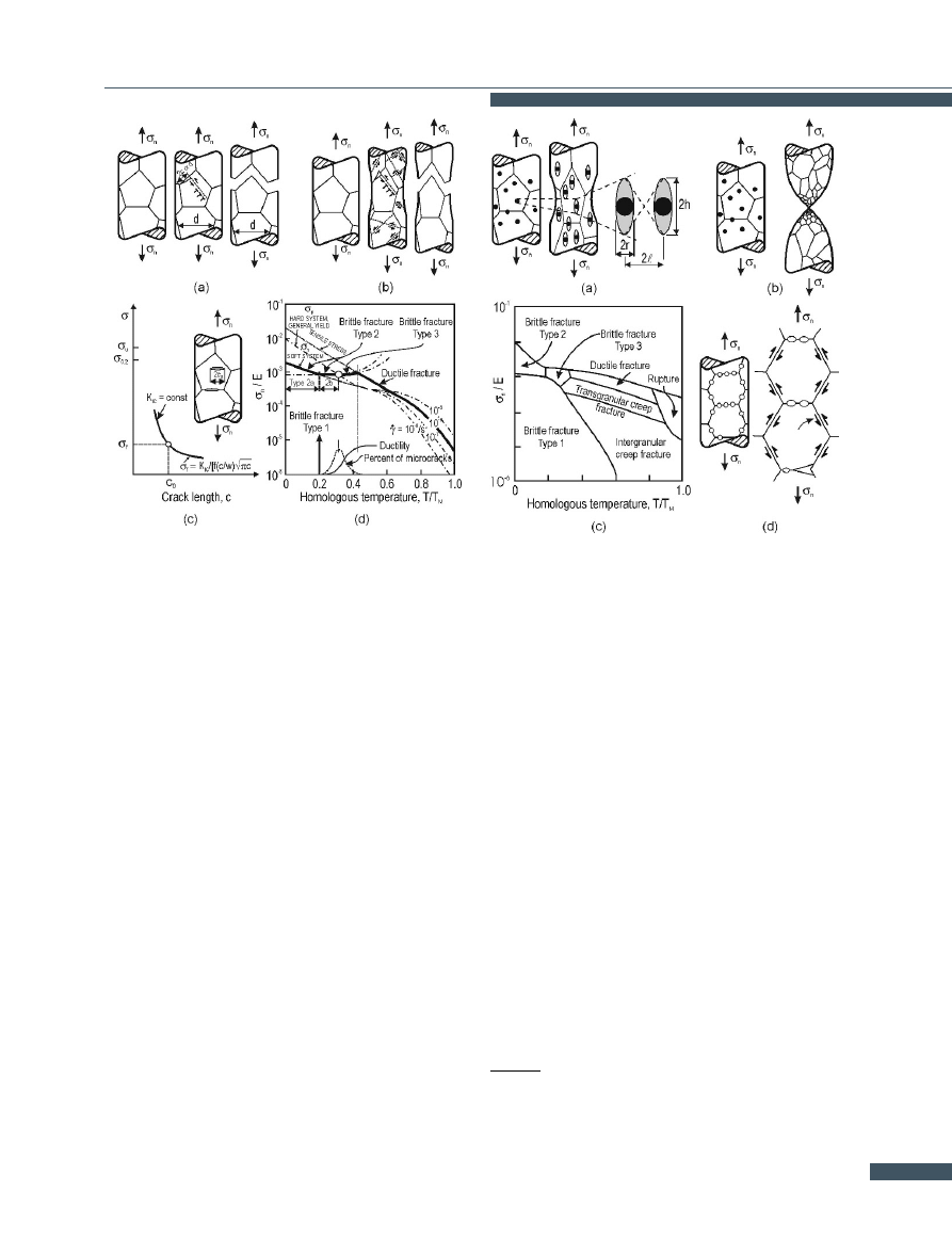
Figure 2.
Mechanisms of brittle fracture: a) type 2, b) type 3, c) type
1, d) definition of the three type of brittle fracture. Based
on [
2.2.
Microscopic views on the mechanism of
fracture
Typical views on fracture mechanisms are presented on
maps of fracture mechanisms (Figs.
and
As the figures show, the brittle fracture mechanisms
(Fig.
a, b) and the ductile fracture ones are explained
quite differently even though both require preceding
plastic deformation.
The brittle fracture mechanism is
explained by the effects of a flat pile-up of disloca-
tions (Fig.
a,b), whereas the ductile fracture mechanism
(Fig.
a) is explained by the nucleation and development
of voids around inclusions and separations. This means
that two different theories of fracture are applied here:
the theory of dislocations in the case of brittle fracture
and a modified theory of the porous body in the case of
ductile fracture [
Problem. Due to the lack of cohesion between the above
theories the causes of the transition from ductility to brit-
tleness (Fig.
d) cannot be clearly explained. Moreover,
the above model of the ductile fracture mechanism does
not explain the fracture of pure metals or the fracture of
monophase metal alloys. Neither does this model gener-
ate any criteria for the control of the trajectory of shear
fracture. Since it is not possible to control the trajectory of
shear fracture, several technical problems, connected with,
Figure 3.
Mechanisms of non-brittle fracture: a) ductile, b) rupture,
c) fracture mechanism map, d) intergranular creep frac-
ture. Based on [
e.g., the precision of die shearing and similar technological
processes, arise. Neither is the problem of shear fracture
trajectory control solved by the theory of adiabatic shear
bands (Fig.
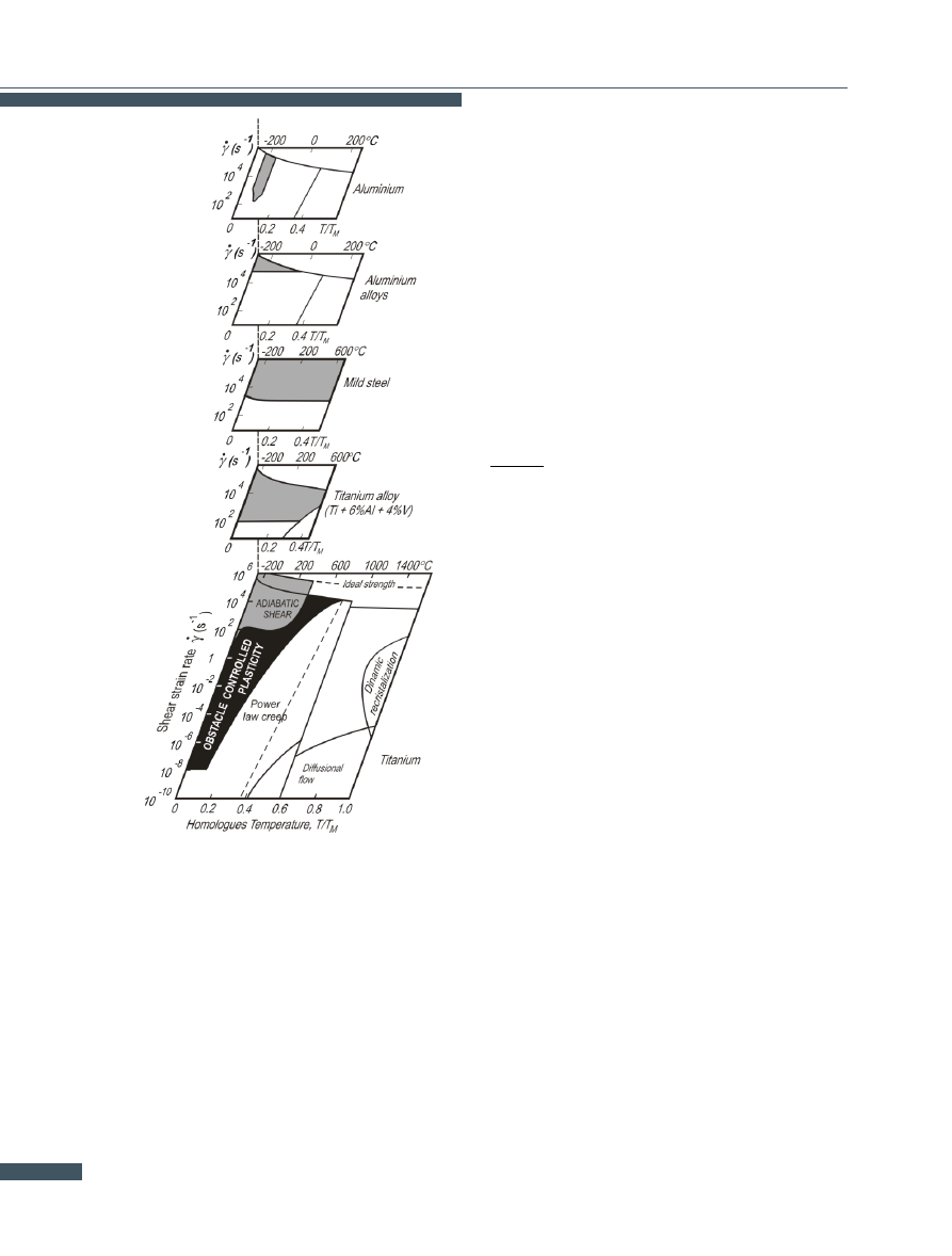
2.3.
Maps of deformation mechanisms
Figure
shows the location of the areas in which adiabatic
shear bands occur depending on the kind of material, the
rate of its deformation, the temperature and the magnitude
of the strains (not shown on the map) grey area in Fig.
According to Fig.
, adiabatic shear bands (ASB) occur
during cold deformation. The presence of adiabatic shear
bands is equated with thermal softening which takes place
in the region of the dislocation mechanism of deformation
(blackened area on Fig.
). Adiabatic shear bands ap-
pear only after critical strain γ
crit
and critical strain rate
γ
∗
crit
are exceeded. Moreover, their appearance largely de-
pends on temperature. In some cases, the temperature is
very low, e.g. for aluminium it is about about 200 degrees
centigrade below zero.
Problem. The theory of adiabatic shear bands does not
explain the mechanism of shear fracture which occurs at
strain rates lower than the critical ones (γ
crit
¡ γ
∗
crit
).
Therefore one can conclude that the shear fracture prob-
219
Physical Concept of Shear Fracture Mesomechanism and its Applications
Figure 4.
Strain rate/homologous temperature deformation maps.
Based on [
lem still is not fully correlated with the dislocation mech-
anism of plastic deformation, although the research on the
evolution of dislocation structures seems to be quite ad-
vanced (Fig.
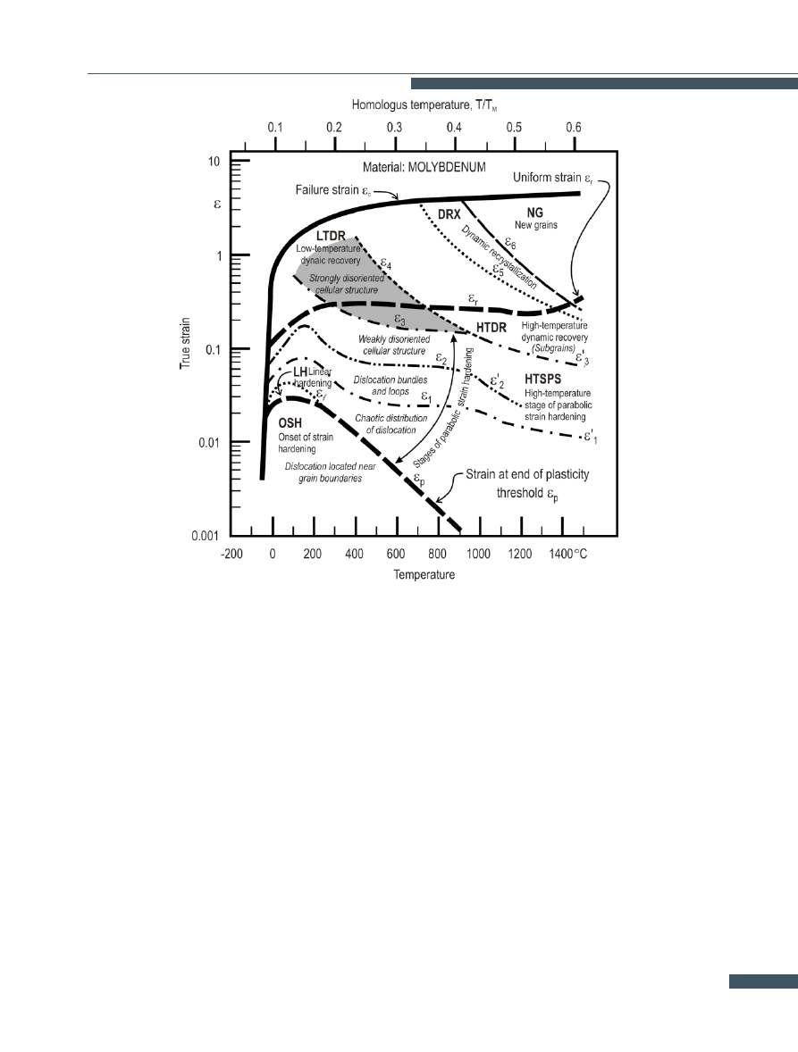
2.4.
Maps of dislocation structures
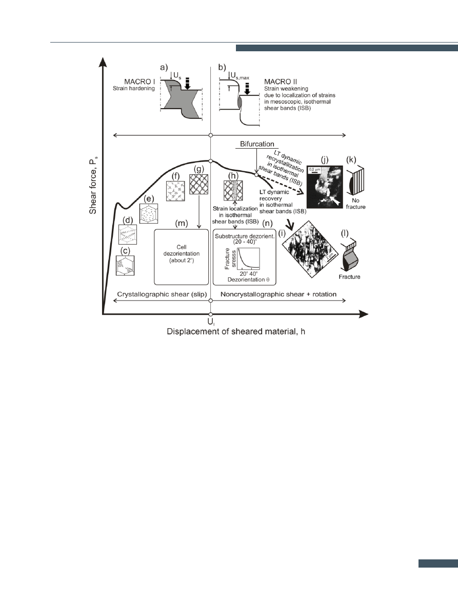
Figure
shows a map of the evolution of dislocation struc-
tures depending on temperature and the magnitude of
strain. Characteristic strain values divide the map into
three main areas separated from each other by thick lines.
The upper limit of the first area marks the strain mea-
sured at the end of the yield threshold (ε
p
). The upper
limit of the second area is marked by uniform strains (ε
r
).
The boundaries of the third area are marked by failure
strains (ε
f
).
Against the background of the three areas the bound-
aries of subareas, corresponding to the successive stages
in the evolution of the dislocation structures, can be dis-
tinguished. No complete coincidence of the boundaries
of the subareas and those of the three main areas is ob-
served, however this poses no problem for the approach
adopted below. The present author proposes to focus on
the subarea with strongly disoriented cellular structure
(the shaded subarea in Fig.
). In the author’s opinion
this subarea is closely linked to the shear fracture mech-
anism.
Problem. The above subarea of strongly disoriented cellu-
lar structure is not contiguous with the failure strain (ε
f
)
curve. In other words, there is still no clear connection be-
tween the evolution of dislocation structures and ductile
fracture, and particularly shear fracture.
This is due to, among other things, the fact that a cellular
structure belongs to low-energy structures, and as such
does not explain the causes of the fracture.
3.
Basic problems, restrictions and
paradoxes resulting from the applica-
tion of the hitherto existing theories of
strain localization and fracture
3.1.
Problems of chip formation mechanism
modeling
The condition and surface properties of a machined mate-
rial and the wear and life of the tools depend on the type
of chip formed during machining. The type of chip also
significantly affects the operation of the machine tools,
especially numerically controlled ones.
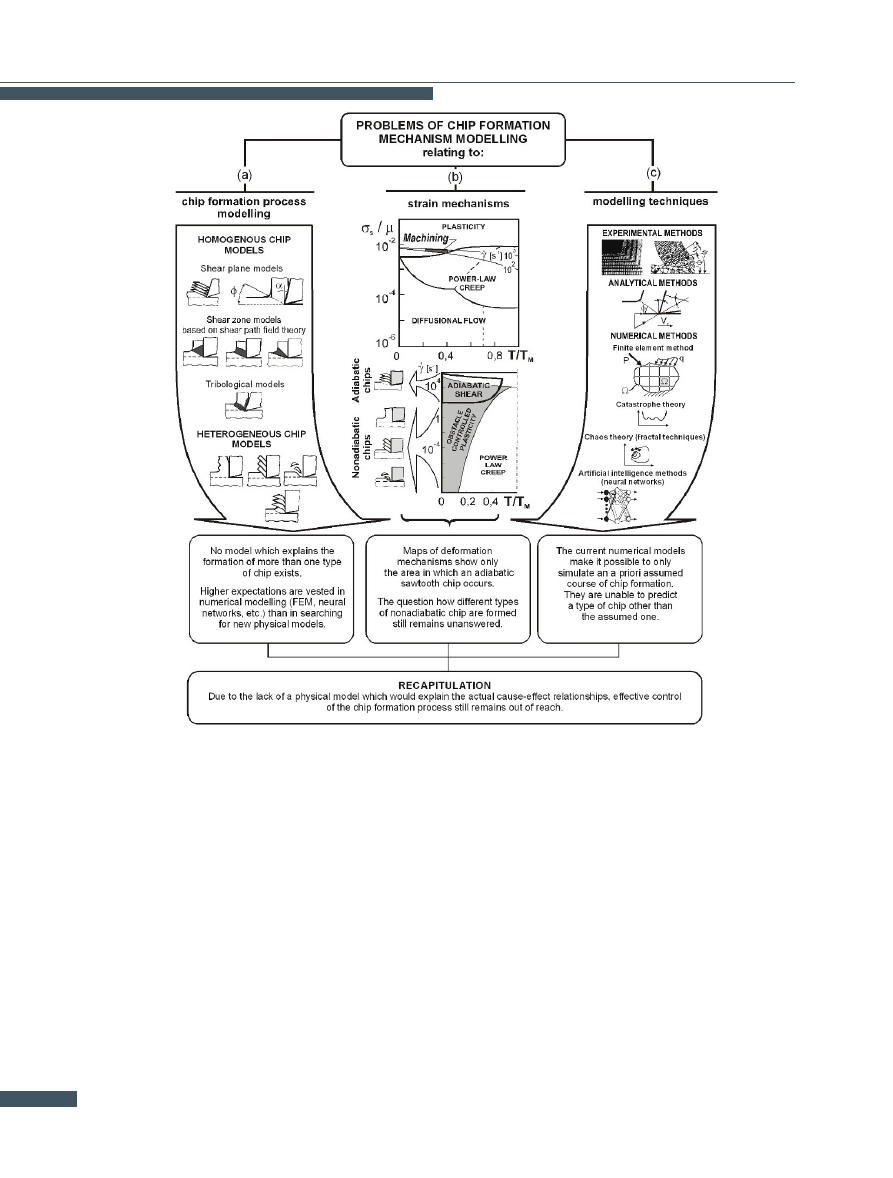
Although there are only three basic types of chip (discon-
tinuous, segmental and continuous) [
], no physical
model exists which would explain why and how a chip of
one type changes into a chip of a different type. Due
to the lack of such a model, the effective control of the
machining process is still unattainable. One should note
that according to the current machinability criteria [
] no
improvement in the machinability of monophase materials
is possible.
The modelling of chip formation has been the subject of in-
tensive researches for a long time. Although many models
220
E. S. Dzidowski
Figure 5.
Map of dislocation structure evolution. Based on [
have been created, some of the first models, i.e. Pispanen’s
model (1937) and Merchant’s model (1945) - Fig.
a, are
most often found in textbooks [
]. This is due to the
fact that none of the more advanced models (Fig.
] explains the formation of more than one type of chip
and usually the stabilized stage in the formation of a ho-
mogeneous chip is modelled.
The basic reason for this state of affairs is the limitations
of continuous medium mechanics due to which the com-
monly used models do not generate fracture criteria and
thus are unable to account for the other types of chip.
The least questionable are sawtooth chip models. They
are probably the only models which are physically and
theoretically well-grounded, since this type of chip can
be easily linked to the presence of adiabatic shear bands
(Fig.
This, however, does not mean that
each sawtooth chip is connected with adiabatic shear [
Moreover the questions of how chips of the other types are
formed and what should determine the boundaries of their
occurrence on maps of deformation mechanisms (Fig.
] still remain unanswered. According to Fig.
b, the
rate of deformation is not a clear-cut criterion for such
demarcation, especially as the occurrence of the particu-
lar types of chip is not accompanied by a change in the
plastic strain mechanism (the shaded areas in Fig.
All of this discourages a search for new physical chip for-
mation models and purely numerical models are used in-
stead (Fig.
]. There are no indications that nu-
merical models represent a viable alternative since they
do not generate any more physics than the one already
contributed by the previously made assumptions based on
the current knowledge about machining.
This means that the modelling of the mechanism of chip
formation and change of one type of chip into another still
remain out of reach.
221
Physical Concept of Shear Fracture Mesomechanism and its Applications
Figure 6.
Synthetic illustration of problems related to chip formation mechanism modelling.
3.2.
Problems and paradoxes of the hitherto
existing limit strain curve concept
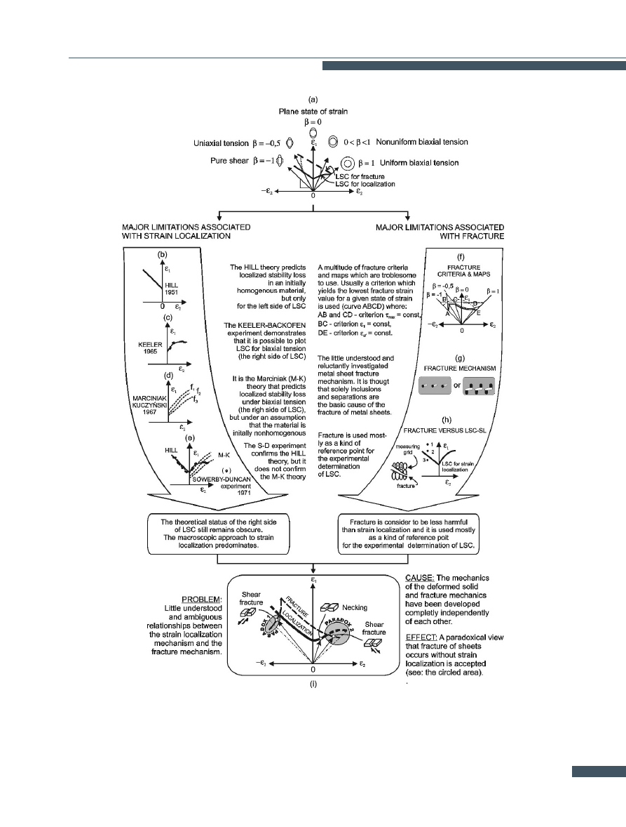
Strain localization and fracture are generally regarded to
be the phenomena which ultimately delimit sheet metal
forming (Fig.
Limit strain curves (LSCs) are most commonly used to de-
termine limit strains relating to the above two limitations.
Although the curves are used to determine the values of
both kinds of limit strains, strain-localization LSCs are
still regarded to be superior. The appearance of a fur-
row − strong local thinning of the formed material - is
thought to be a tangible sign of strain localization. This
strain localization criterion is purely geometric. Further-
more, different strain localization criteria have to be used
for different states of strain (the problem of LSCs’ left and
right side) - Fig.
b,d. In the author’s opinion, identifying
strain localization exclusively with local thinning of the
material ignores the physical sense of this phenomenon
and blurs its close link to fracture.
The use of necking as a strain localization criterion and
the treatment of sheet metal fracture as a sort of refer-
ence point for the experimental determination of LCSs
(Fig.
g) is a source of fallacious notions about the strain
localization-fracture relationship (Fig.
In the author’s opinion the view that in certain strain in-
tervals fracture occurs without strain localization (Fig.
is paradoxical. This view concerns the forming of sheet
222
E. S. Dzidowski
Figure 7.
Synthetic illustration of problems related to limit strain curves (LSCs) construction.
223

Physical Concept of Shear Fracture Mesomechanism and its Applications
metal by close to pure (cup) drawing (the left side of LSCs
- paradox 1) and forming close-to-uniform biaxial tension
(the right side of LSCs - paradox 2) - Fig.
i. This leads
to false notions about the relationships between strain
localization and sheet metal fracture in different states of
strain, and to incorrect estimates of the limit strains.
4.
Mesoscopic-macroscopic
con-
cept of fracture of materials accom-
panying large plastic deformation
The mesoscopic-macroscopic concept of the shearing pro-
cess, proposed by the author of this paper, is illustrated in
Figs.
and
]. According to this concept, the onset
(Fig.
b) and then the development of strain localization
in mesoscopic shear bands (Fig.
a) are of key importance.
Here a case of strain localization in quasi-isothermal,
mesoscopic shear bands (SB) is considered. The develop-
ment of shear bands manifests itself in the appearance of
a lenticular strain localization zone (Fig.
b). The begin-
ning of strain localization in the mesoscopic shear bands
puts an end to the displacements of the free surface: U
s
= U
s,max
(Fig.
a, b). The moment when shear bands
appear and the free surface displacements are inhibited
can be easily predicted. It is enough to know the rela-
tionship between limiting strain U
l
and strain-hardening
coefficient n [
]. Strain (displacement) U
l
is limiting
from the strain localization point of view. The development
and properties of the dislocation structure within shear
bands (Fig.
h, i, j) determine the susceptibility of the
material to fracturing along the shear bands. The origi-
nal grain boundaries become defective as a result of the
interaction between them and the shear bands (Fig.
boundary GB2). This means that the course and effects
of the shearing process depend here only on the synergy
between the strain localization mechanism and the mech-
anism of fracture along mesoscopic shear bands.
The macroscopic course of fracture depends on the
shape of the boundaries of the strain localization zone
(Fig.
b,
b) and the magnitude of the displacements of
the material along the defective grain boundaries (Fig.
5.
Mesoscopic-macroscopic model
of shear fracture mechanism
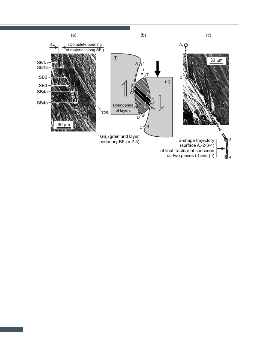
As Fig.
shows, the fracture of the sheared material con-
sists in its separation along mesoscopic shear bands SB
(Fig.
a, separation ∆L)). Initially the fracture propagates
along the shear bands (Fig.
b, trajectories A-B and E1-
D1) and it consists in the loss of cohesion between the
particular layers of the material. As the fracture reaches
points 2 and 3, the fracture mechanism changes. From
now on the fracture propagates only along the defective
grain boundaries (Fig.
b, line 2-3 and Fig.
a, boundary
GB2).
Hence the final shape of fracture surface A-2-3-4’ and that
of surface A1-2-3-4 depend on the shape and width of the
lenticular strain localization zone and on the magnitude
of the displacements along the defective grain boundaries
(Fig.
a, b). This means that the fracture initially prop-
agates along the boundaries and then across the strain
localization zone formed by the shear bands (Fig.
b,
c). Characteristically, the strain localization zone shrinks
from top and bottom and eventually widens as a result
of intercrystalline displacements of the material. Immedi-
ately before the total separation of the sheared material
into two parts, the zone assumes a shape similar to par-
allelogram BCE
1
F
1
(Fig.
b, blackened area). The above
shear fracture mechanism model relates fracture not only
to the properties (misorientation) of the material’s sub-
structure within shear bands, but also to transverse (acting
transversely to the direction in which shear bands (SBs)
develop) tensile stresses. Such stresses may arise nat-
urally or be artificially generated as in shear with ten-
sion. One should note here that the effective value of
artificially generated tensile stresses amounts to about
0.25 of the yield point value (σ
0.2
). Conventional shear-
ing (Fig.
) is an example of the natural generation of
transverse tensile stresses. The stresses arise because of
interaction between SBs and the original grain bound-
aries (see Fig.
a, GB2). The development of shear bands
results in strong flattening and rotation of the grains and
in the formation of characteristic laminar lenticular strain
localization zones (SLZ). This may be accompanied by the
formation of wedge-shaped discontinuities along the orig-
inal grain boundaries (see Fig.
a, GB2). The tendency
to form such discontinuities depends to a large degree
on the condition of the original grain boundaries. One
of the factors conducive to the lamination of the origi-
nal grain boundaries may be adsorption of foreign atoms.
The defective grain boundaries become similar to inclined
planes whereby the sheared portions of material move and
separate along the SBs (Fig.
a, shear bands SB1-SB4
and the next ones). The separation is the most complete
near the boundaries of SLZs, i.e. at the places where
displacement (non-dilatational strain) gradients are the
steepest (see Fig.
a and b). To sum up, the shape of
shear fracture trajectories depends here on: the way in
which shear bands develop, the properties of the shear
bands, the condition of the original GBs and the shape of
the SLZ formed by the mesoscopic SBs. This means that
224
E. S. Dzidowski
Figure 8.
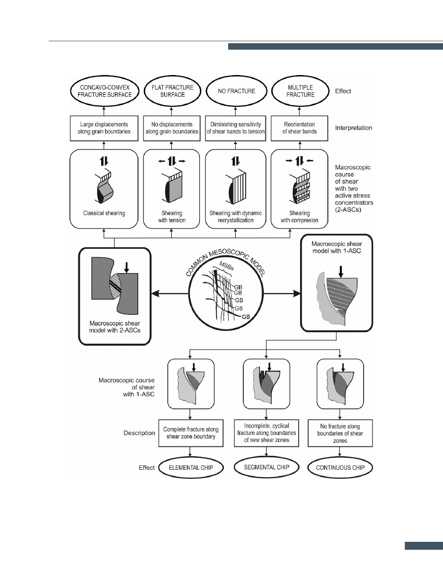
Mesoscopic-macroscopic concept of shearing. According to E.S. Dzidowski. Description in text.
by properly changing the properties and direction of de-
velopment of shear bands and the way in which transverse
tensile stresses are generated one can change the shape
of the shear fracture trajectories or totally eliminate the
fracture.
6.
Criteria and principles of frac-
ture control resulting from the meso-
scopic concept of shear fracture
The presented mesoscopic-macroscopic concept of the
physical modelling of the shearing process generates cri-
teria for the effective control of processes based on the
shearing of materials.
The criteria include everything
which affects strain localization in mesoscopic shear bands
and the properties of the dislocation structure formed
within the shear bands. Depending on the needs, stack-
ing fault energy, the strain hardening ability of the ma-
terial, the angle of disorientation of the substructure
formed within the shear bands, the direction in which the
shear bands propagate, the original condition of the grain
boundaries, the location of the strain localization zone and
so on can be such a criterion. Selected examples illus-
trating the possibilities of controlling the shearing process
are shown in Fig.
6.1.
General mesoscopic-macroscopic crite-
ria and principles of fracture control in pro-
cesses based on material shearing
Figure
shows mainly the influence of: the length of
the material’s cropped part, the additional state of stress,
and the properties of the shear bands on the course and
225
Physical Concept of Shear Fracture Mesomechanism and its Applications
Figure 9.
Model of shear fracture mechanism (b) and scanning electron microscopy results which validate it (a, c). According to E.S. Dzidowski.
Description in text.
effects of shear fracture. According to figure
, a change
in the length of the cropped part leads to a change in the
kind of process. In the considered case, the processes are
cropping and orthogonal cutting (machining). They differ
only in the shape of the macroscopic strain localization
zone (MSLZ) and the way in which the latter develops.
In the case of cropping, the zone assumes the shape of
a biconvex lens whose axis is parallel to the direction of
shearing. In the case of machining, the MSLZ assumes the
shape of a half-lens whose axis is skew to the direction of
shearing. Because of the skewness of the axis machining
is a process of cyclic formation of countless MSLZs, owing
to which a chip forms.
The type of chip depends solely on the properties of the
substructure forming within mesoscopic shear bands. This
means that:
• the same phenomenon, the localization of strains in
mesoscopic shear bands, underlies both processes;
• the direction of development and shape of the frac-
ture trajectory depend on the shape of the MSLZ
and the way in which the transverse tensile stresses
are generated;
• the material’s tendency to shear fracture depends
solely on the properties of the substructure which
forms within shear bands.
Further to the above, the issue arises on how the proper-
ties of the substructure may be changed within the meso-
scopic shear bands.
6.2.
Stacking fault energy as a criterion
for controlling the mesoscopic-macroscopic
mechanism of formation of various chip types
In the mesoscopic-macroscopic concept of shear fracture
mechanism presented above, the chip type depends on the
tendency of the material to fracture along the boundary of
the macroscopic zone of strain localisation. At the same
time, the tendency for shear fracture is itself dependent
on the course and effects of the evolution of dislocation
structures. One may conclude that the method to change
the chip type may consist in changing the stacking fault
energy. This is due to the fact that the course of the
evolution of dislocation structures depends on the stacking
fault energy, which is shown in figure
The research
conducted by the author of the aforementioned paper in
collaboration with his co-worker indeed confirmed such
226
E. S. Dzidowski
Figure 10.
Examples of interpretation possibilities of mesoscopic-macroscopic model of shear mechanism (according to E. S. Dzidowski).
227
Physical Concept of Shear Fracture Mesomechanism and its Applications
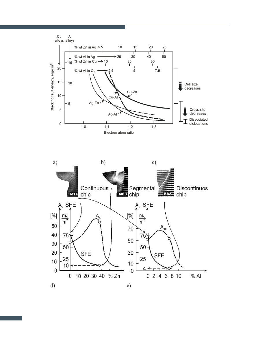
Figure 11.
Dependence of dislocation cell size and tendency for cross-slip and dissociation of dislocations on stacking fault energy in copper and
silver alloys. Based on Swann 1963.
Figure 12.
Influence of stacking fault energy on the type of chip (according to Dzidowski, Chruscielski).
228

E. S. Dzidowski
possibility, which is illustrated in the figure below [
As figure
shows, reducing the stacking fault energy
(SFE) leads to a change in the type of chip from continu-
ous (Fig.
a) to segmental (Fig.
b) and discontinuous
chip (Fig.
c). It should be noted that the chips formed
during intense shear fracture (segmental and discontinu-
ous chips) have been obtained in the materials more plas-
tic (Cu + 37.4% Zn), or as plastic as (Cu + 7.2% Al) plain
copper (see figure
: values A
5
and A
10
). This means
that the equals sign currently put between the discontin-
uous chip and the brittleness of the machined material, or
the presence of brittle particles [
], shall be deemed as
dramatically inefficient or even incorrect, as brittle frac-
ture has been confirmed in none of the examined materials
(Fig.
). This also means that the stacking fault energy
may become a new and effective criterion for controlling
the mesoscopic mechanism of chip formation during the
machining, as well as for other similar processes, includ-
ing abrasive wear.
6.3.
The way of developing shear bands as
a criterion for the modification of the existing
shape of the diagram of metal sheet limit defor-
mation
Identifying strain localization exclusively with local thin-
ning of the material ignores the physical sense of this phe-
nomenon and blurs its close link to fracture. This leads to
false notions about the relationships between strain local-
ization and sheet metal fracture in different states of strain
and to incorrect estimates of the limit strains (Fig.
i). The
author’s analysis of the problem and the results of his in-
vestigations into the strain localization mechanism and
the fracture mechanism under large plastic strains have
led him to the following conclusions:
1. It is possible to apply one criterion valid for the whole
range of strain. This criterion should define only the con-
ditions for the onset of strain localization understood as
an intramaterial phenomenon.
2. Shear fracture of cold-formed sheet metal cannot occur
without prior strain localization.
3. The critical strain value for fracture is always higher
than the one for the onset of strain localization and the
difference between them depends on the mode in which
strain localization develops. The above theses were in-
corporated into a new conception of the limit strain curve
(Fig.
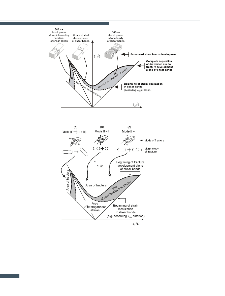
This conception is based on the assumption that the strain
localization and fracture mechanisms in sheet metal have
a common origin and there is a synergy between them.
In fact, according to the proposed conception, there is
only one strain localization mechanism: strain localiza-
tion in shear bands. The way in which shear bands de-
velop determines only the macroscopic course of strain
localization and the prior-to-fracture strain values. The
maximum shear stress criterion, which defines the shape
of the strain-localization limit strain curve (SLLSC), was
adopted as the strain localization onset criterion. The
fracture limit strain curve (FLSC) is situated above SLLSC
for the whole range of stress. The distance between the
two curves depends mainly on the way in which strain lo-
calization develops, i.e. on the concentrated or dispersed
development of shear bands. The fracture mechanism is
closely bound up with the development of shear bands.
The mode of fracture is determined by the local state of
stress and as a result, by the state of strain (Fig.
Experiments were carried out [
] to validate the assump-
tions of the above LSC conception, to determine the mech-
anism and mode of strain localization development de-
pending on the state of strain and to establish the re-
lationship between the investigated phenomena and limit
strain values. Scanning microscopy was employed. The
mechanisms and modes of the development of the phe-
nomena were determined by examining the development
of shear bands and by fractography.
The results of the investigations challenge the universality
and meaning of the ”furrow” strain localization criterion.
It has been found that an occurrence of strain localization
does not necessarily entail the appearance of a ”furrow”
or apparent disturbance of the sheet metal forming pro-
cess. Shear bands can develop in both concentrated and
dispersed mode. Thus the mode in which shear bands de-
velop determines the macroscopic manifestations of strain
localization and the critical strain values as regards frac-
ture. This means that by ”dispersing” the development of
shear bands one can prevent the appearance of a ”furrow”
and to increase the fracture related critical strains. In
this way the strain localization-fracture relationships for
the right side of LSC have been explained and thus the
dilemma arising from the inapplicability of the Hill crite-
rion [
] and the limitations of the Marciniak-Kuczyński
theory [
] for this side of LSC has been solved.
7.
The prospects for development
and further application of mesome-
chanics of failure and fracture of ma-
terials
The abovementioned examples of the application of the
mesoscopic-macroscopic shear fracture concept and model
do not fully exhaust all the possible applications of this
model. This is due to the fact that this model gener-
229
Physical Concept of Shear Fracture Mesomechanism and its Applications
Figure 13.
Proposed new, mesoscopic concept of limit diagram for metal sheet forming.
Figure 14.
Effect of state of strain on mode and morphology of sheet metal fracture.
ates both the criteria for predicting the commencement
of fracture, and the criteria for controlling the course of
and/or the criteria for preventing shear fracture. Conse-
quently, this model may be applied wherever large local
plastic deformations occur as a result of the development
of mesoscopic isothermal shear bands [
]. These ex-
amples have made it possible to prove that the physical
approach to shear fracture mesomechanism offers much
230

E. S. Dzidowski
broader cognitive and utilitarian opportunities than the
existing purely mathematical methods, as presented e.g.
in [
]. This is due to the fact that the physical ap-
proach allows for a deeper understanding of shear fracture
meso- and macromechanism, and generates new criteria
controlling this mechanism. More details and experimen-
tal verifications of the concept presented here can be found
in earlier author’s publications [
]. For further argu-
ments for the effectiveness of mesomechanical concept of
fracture see papers [
References
[1] Timoshchenko V.A., Elements of theory and technol-
ogy of die shearing and cropping processe, Shtiintsa,
Kishinev, 1979 (in Russian)
[2] Belyaev V.I., Engineering theory of plasticity, Science
and Technology, Minsk, 1985 (in Russian)
[3] Gurson A.L., Continuum theory of ductile rupture by
void nucleation and growth, I. Yield criteria and flow
rules for porous ductile media, J. Eng. Mater. Technol.,
1977, 99, 2,15
[4] Needleman A., Tvergaard V., An analysis of ductile
rupture in notched bars, J. Mech. Phys. Solids, 1984,
32, 461-490
[5] Gandhi C., Ashby M. F., Fracture-mechanism maps
for materials which cleave: FCC, BCC and HPP met-
als and ceramics, Acta Metallurgica, 1979, 27, 1565-
1602
[6] Ashby M. F., Gandhi C., Taplin D. M. R., Fracture-
mechanism maps and their construction for FCC met-
als and alloys, Acta Metallurgica, 1979, 27, 699-729
[7] Sarget P.M., Ashby M. F., Cambridge Univ. Engng.
Dept. Report No. CUEDCMATSTR.98, 1983
[8] Bai Y., Dodd B., Adiabatic shear localization. Oc-
currence, theories and applications, Pergamon Press,
Oxford, 1992
[9] Firstov S.A., Pechkovski E.P., Voprosy Materialobe-
deniya, 2002, 29, 70
[10] Komanduri R.,Brown R.H., On the Mechanics of Chip
Segmentation in Machining, Journ. of Engineering for
Industry, Trans. ASME, 1981, 103, 33-51
[11] Jawahir I.S.,van Luttervelt C.A., Recent Developments
in Chip Control Research and Applications, Annals of
CIRP, 1993, 42/2, 659-693
[12] van Luttervelt C.A., Childs T.H.C., Jawahir I.S., Klocke
Fet al., Present Situation and Future Trends in Mod-
elling of Machining Operations, Annals of CIRP,
1998, 47/2, 587-626
[13] Higgins R.A., Engineering Metallurgy. Part I Applied
Physical Metallurgy, Edward Arnold, A division of
Hodder and Stoughton, London, 1993
[14] Merchant M.E., Mechanics of the metal cutting pro-
cess, Journal of Applied Physics, 1945, 16/5, 318-324
[15] Shaw M.C., Metal Cutting Principles, Oxford Pub.,
1984
[16] Astakhov V.P., Metal Cutting Mechanics, CRP Press
LLC, London, 1998
[17] Hill R., The Mathemalical Theory of Plasticity, Ox-
ford University Press, London, 1950
[18] Hill R., The Mechanics of Machining: A New Ap-
proach, J. Mech. Phys. Solids, 1954, 3, 47
[19] Shi T., Ramalingam S., Slip-line Solution for Orthog-
onal Cutting with a Chip Breaker and Flank Wear, Int.
J. M. Sci., 1991, 33, 9
[20] Black J.T., Briggs N.D., Huang J., Payton L.N., Or-
thogonal Machining of Metals, In: II International
Conference on Advances in Production Engineering
APE, 2001, Warsaw, 2001
[21] Recht R.F., Catastrophic Thermoplastic Shear, Jour-
nal of Applied Mechanics, 1964, 6, 189-193
[22] Recht R.F., A Dynamic Analysis of High, Speed Ma-
chining, Journal of Engineering for Industry, 1985,
107, 309-315
[23] Vyas and Shaw M.C. Mechanics of Saw-Tooth Chip
Formation in Metal Cutting, Journal of Manufacturing
Science and Engineering, 1999, 121, 163-172
[24] Bai Y., Dodd B., Adiabatic Shear Localization, Perg-
amon Press, 1992
[25] Dzidowski E.S., Chru.cielski G., Mesomechanistic
Concept of Metal Cutting Processes, In:
A. M.
Habraken (Ed.) Proceedings of 4th International
ESAFORM Conference on Material Forming, (April
23-25, 2001 Liege Belgium) Deroaux Ordina, 2001,
635-638
[26] Frost H.J., Ashby M.F., Deformation, Mechanism
Maps, The Plasticity and Creep of Metals and Ce-
ramics, Pergamon Press, Oxford, New York, Toronto,
1982
[27] Marinov V.R., Hybrid analytical-numerical solution
for the shear angle in orthogonal metal cutting, Part
I: theoretical foundation, International Journal of Me-
chanical Sciences, 2001, 43, 399-414
[28] Lin Z-C., Lin Y-Y, Fundamental Modeling for Oblique
Cutting by Thermo-elastic-plastic FEM, Int. Journal
of Mechanical Sciences, 1999, 41, 941-965
[29] Hamman J.C., Meslin F., Donyo S., Phenomenologi-
cal Modeling of Chip Segmentation Using the Catas-
trophe Theory, In: The 4th International ESAFORM
Conference on Material Forming, Liége, Belgium,
2001
231

Physical Concept of Shear Fracture Mesomechanism and its Applications
[30] Masory O., Monitoring Machining Processes Using
Multi-sensor Readings Fused by Artificial Neural
Network, J. Mat. Proc. Technol. 1991, 28 , 231-240
[31] Dzidowski E.S., Mechanism of Shear Fracture in the
Aspect of Controlled Decohesion of Metals, Scien-
tific Papers of the Technical University of Wroclaw,
Monographs No. 11, Wroclaw, 1990 (in Polish)
[32] Dzidowski E.S., Microscopic-macroscopic concept of
physical modelling and controlling shear fracture and
processes determined by this fracture, Physical Me-
somechanics, 2004, 7, 75-80
[33] Dzidowski E.S., Chruscielski G., Effect of stacking
fault energy on mesoscopic-macroscopic mechanism
of chip formation during shearing with single con-
centrator of stresses (during machining), Mechanical
Review, 2005, 7-8, 31-34 (in Polish)
[34] Dzidowski E.S., Cisek W., Non-homogeneity of de-
formation and fracture in sheet metal forming under
biaxial stretching, Archives of Metallurgy, 1999, 44,
403-419
[35] Hill R., On discontinuous plastic states, with special
reference to localized necking in thin sheets, J. Mech.
Phys. Solids, 1952, 1, 19-30
[36] Marciniak Z., Kuczynski K., Limit strains in the pro-
cesses of stretch-forming sheet metal, Int. J. Mech.
Sci., 1967, 9, 609
[37] Dzidowski E.S., How to design, manufacture and ex-
ploit pipes for secure operation under pressure, Rudy
i Metale, 2008, R53, 714-721 (in Polish)
[38] Dzidowski E.S., The mesoscopic mechanism of the
isothermal shear fracture of aluminium alloys. In: ed.
Hirsh J., Skrotzki B., Gottstein G. (Eds.), Aluminium
Alloys:
their physical and mechanical properties,
(2008 Weinheim), Wily-VCH, 2008, 1844-1949
[39] Wei Yang, Lee W. B., Mesoplasticity and its applica-
tions, Springer-Verlag, Berlin Heidelberg 1993
[40] Kafka V., Inelastic mesomechanics, World Scientific,
Singapore 1987
[41] Kafka V., Mesomechanical constitutive modeling,
World Scientific, Singapore 2001
[42] Murayama Y., Mesoscopic systems, Wiley-Vch, Wein-
heim 2001
[43] Dzidowski E.S., Problems of numerical modeling of
processes determined by shear fracture, In: Mate-
rials processing and design. Modeling, simulation
and applications, Proceedings of the 9th Interna-
tional Conference on numerical Methods in Industrial
Forming Processes, NUMIFORM 2007 (June 17-21,
2007 Porto Portugal) American Institute of Physics,
2007,1615-1620
[44] Dzidowski E.S., Shear fracture mesomechanics: new
modelling strategies and criteria, In: Sih G. C. and
de Castro M. S. T.( Eds.), Multiscale behaviour of
materials and structures: analytical, numerical and
experimental simulation, Proceedings of the VIII In-
ternational Conference of Mesomechanics (July 19-
22, 2006 Porto Portugal), Porto Publindustria, 2006,
83- 90
[45] Dzidowski E.S., Physical mesomechanics as a missing
link needed to understand, model and control of main
aspects of plasticity and fracture of ductile materials,
In: Sih G. S. and Vu-Khanh T. (Eds.) Materials for
safety and health. Mesoscopic and multiscale consid-
eration in modern science and engineering (August
1-4, 2005 Montreal Canada), Ecole de Technologie
Superieure, 2005, 312-319
[46] Dzidowski E.S., Some critical remarks about applica-
tion of known fracture criteria in modelling processes
determined by shear fracture, In: Stoeren S. (Ed.)
the 7th Esaform Conference on material Forming.
ESAFORM 2004 (April 28-30, 2004 Trondheim Nor-
way) Proceedings of Norwegian University of Science
and Technology, 2004, 745-748
[47] Dzidowski E.S., Chruscielski G., Mesoscopicmacro-
scopic model of chip formation during machining i
quasi-isothermal conditions, In: Brucato V. (Ed.) Pro-
ceedings of the 6th ESAFORM Conference on Mate-
rial Forming (April 28-30, 2003 Salerno Italy), Nuova
Ipsa Editore, 2003, 523-526
[48] Dzidowski E.S.,
Advancements of fracture me-
somechanics in sheet metal forming processes, In:
Habraken M. (Ed.) Proceedings of the 6th ESAFORM
Conference on Material Forming (April 23-25, 2001
Liege Belgium), Derouaux Ordina, 2001, 241-244
[49] Dzidowski E.S., Sheet limit-strain-curve concept
based on structural aspects of nucleation and de-
velopment of strain localization on shear bands, In:
Fritz H. G. (Ed.) 3rd ESAFORM Conference on Ma-
terial Forming (April 11-14, 2000 Stuttgart Ger-
many), Institute fuer Kunstofftechnologie Universitaet
Stuttgart, 2000
[50] Dzidowski E. S., Shear fracture at liquid nitrogen
temperature, Materials Science and Engineering, A
Structural Materials: Properties, Microstructure and
Processing, 1993, 168, 11-16
[51] Dzidowski E.S., The mechanism of shear fracture in
the aspect of micro- and macrolocalization of strains,
In: Teodosiu C. and Sidoroff R. F. (Eds.) Fundamental
aspects and applications to metal forming, Proceed-
ings of the International Seminar MACAMAT’91 (Au-
gust 7-9, 1991 Fontainebleau France), A. A. Balkema,
1993, 213-218
232

E. S. Dzidowski
[52] Dzidowski E.S., The genesis of s-like fracture shape
during transverse shearing of metals, In: Anisotropy
and localization of plastic deformation, Proceedings
of Plasticity’91: The Third International Symposium
on Plasticity and Its Current Applications (August 12-
16, 1991 Grenoble France), Elsevier,1991, 67-74
[53] Dzidowski E.S., The mechanism of ductile fracture
during transverse shearing, In: Lange K. (Ed.) Ad-
vanced Technology of Plasticity 1987 (August 24-
28, 1987 Stuttgart Germany), Springer Verlag, 1987,
283-290
[54] Dzidowski E.S., A study of limiting displacements in
the shearing of bars, Journal of Mechanical Working
Technology, 1986, 12, 297-306
[55] Dzidowski E.S., The occurrence of localized shear
bands during transverse shearing, In: COBEM’85,
Annalis do VII Congresso Brasileiro de Engenharia
Macanical (Dezembro 10-13, 1985 Sao Jose dos
Campos), 907-910
[56] Dzidowski E.S., The effect of strain hardening factor
on limiting displacements during transverse shear-
ing, In: Conference proceedings of 1st ICTP advanced
technology of plasticity 1984 (September 3-7, 1984
Tokyo Japan), 617-622
[57] Mishnaevsky L.L. Jr, Methods of the theory of com-
plex systems in modelling of fracture: A brief review,
Engineering Fracture Mechanics, 1997, 56, 47-56
[58] Panin V.E., Physical fundamentals of mesomechan-
ics of plastic deformation and fracture of solids, Acta
Metallurgica Sinica, 1997, 33, 187-197
233
Document Outline
- Introduction
- Hitherto existing views on the mechanisms of fracture of materials
- Basic problems, restrictions and paradoxes resulting from the application of the hitherto existing theories of strain localization and fracture
- Mesoscopic-macroscopic concept of fracture of materials accompanying large plastic deformation
- Mesoscopic-macroscopic model of shear fracture mechanism
- Criteria and principles of fracture control resulting from the mesoscopic concept of shear fracture
- The prospects for development and further application of mesomechanics of failure and fracture of materials
- References
Wyszukiwarka
Podobne podstrony:
eng 11 03 2011
NiteRider catalog lampek 2011 eng
egz dyplom I st ENG ECiJ 2011 2012, Energetyka-ECiJ, Egzamin Dyplomowy
egz dyplom I st ENG EK 2011 2012, PWr W9 Energetyka stopień inż, VII Semestr, EGZAMIN DYPLOMOWY, Sta
NATO strategic concept 2010 eng
eng 11 03 2011
chess magazine eng 10 2011
Bartosiewicz, Bartosz; Pielesiak, Iwona How to Measure Territorial Cohesion of a Metropolitan Area
test eng kl2 2011 12
Ghostbusters Sanctum of Slime 2011[Multi ENG
chess magazine eng 08 2011
chess magazine eng 09 2011
NiteRider catalog lampek 2011 eng
Demidov A S Generalized Functions in Mathematical Physics Main Ideas and Concepts (Nova Science Pub
Collection of Manak Gathas Comp by Manak Disciples Society Eng Trn by dr Lee Chi Ran 2nd edn (201
2011 2 KOSZE
higiena dla studentów 2011 dr I Kosinska
więcej podobnych podstron